1
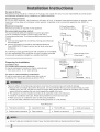
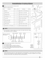
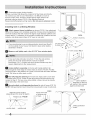
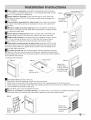
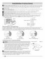
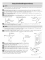
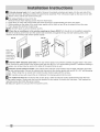
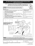
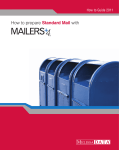
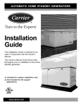
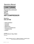
READ BEFORE iNSTALLiNG
UNiT
For Slider Casement Air Conditioners
To avoid risk of personal injury, property damage, or product damage due to the weight of this device and sharp
edges that may be exposed:
Air conditioners covered in this manual pose an excessive weight hazard. Two or more people are needed to
move and install the unit. To prevent injury or strain, use proper lifting and carrying techniques when moving unit.
Carefully inspect location where air conditioner will be installed. Be sure it will support the weight of the unit over
an extended period of time.
Handle air conditioner with care. Wear protective gloves whenever lifting or carrying the unit. AVOID the sharp
metal fins of front and rear coils.
Make sure air conditioner does not fall during installation.
• These instructions describe installation in a typical wood framed window with a wood SLIDE-BY sash, or
installation in a metal CASEMENT window. Modification may be necessary when installing in windows made
differently than those shown in these instructions.
A high window accessory kit is available for window heights up to 62" (1575 mm). Part # EA103W.
Call 1-800-4-MY-HOME to order kit.
Meeting
Electrical
Requirements
Electrical Shock and Personal Injury Hazard
• Electrical ground is required on this appliance.
o DO NOT ground to a gas line.
• If cold water pipe is interrupted by plastic, non-metallic gaskets, or other insulating materials, DO NOT use for
grounding.
• Check with a qualified electrician if you are in doubt as to whether the appliance is properly grounded.
• DO NOT modify power supply cord plug. If it does not fit outlet, have a proper outlet installed by a qualified
electrician.
o DO NOT have a fuse in the neutral or grounding circuit. Afuse in the neutral, or grounding circuit could result in
an electrical shock.
• DO NOT use an extension cord with this appliance.
Failure to follow these instructions could result in electrical shock, serious injury, or death.
OBSERVE ALL LOCAL GOVERNING CODES AND ORDINANCES.
REMOVE THE POWER SUPPLY CORD GROUNDING PRONG.
DO NOT, UNDERANY
CIRCUMSTANCES,
• If codes permit, and a separate grounding wire is used, it is recommended that a qualified electrician determine
that the grounding path is adequate and not interrupted by plastic, non-metallic gaskets, or other insulating
materials.
2020217A1406
Receptacle
Wiring:
Receptacle
wiringshouldbea minimum
of 14gauge.Usecopperwireonly.It isyourresponsibility
toprovideproper
andadequate
receptacle
wiring,installedbya qualifiedelectrician.
ElectricalRequirements:
A 115volt(103.5minimum,126.5maximum),
60Hertz,AConly,15amperefusedelectricalsupplyisrequired.Atime
delayfuseortimedelaycircuitbreakeris alsorequired.
A separatecircuit,servingthisapplianceonly,MUSTbe
provided.
ElectricalConnection:
3-ProngGrounding
Electricalgrounding
is requiredonthisappliance.
Recommended
groundingmethod:
TypeWallReceptacle_
Foryourpersonal
safety,thisappliancemustbegrounded.
3-Prong
Thisairconditioner
includesa powersupplycordwitha
Grounding plug
3-pronggroundingplug.Tominimizepossibleelectricalshock
hazard:
cordmustbepluggedintoa matching3-pronggrounding
type
wallreceptacle.
mustbegroundedinaccordance
withNationalElectrical
Grounding prong
Code(ANSI/NFPA
70-latest
version)andalllocalcodesand
ordinances.
If a matching3-pronggrounding
typewallreceptacle
is notavailable,
it istheresponsibility
oftheconsumer
to havea properlygrounded
3-prongwallreceptacle
installedbya qualifiedelectrician.
t
Power Supply
(6 feet long)
Cord
FIG. 1
Preparing
wood strip
mounted on
top of inner sill
for Installation
Installation Tips
For wood=frame casement windows:
It may be necessary to construct a frame, using at least
1" thick wood, with a 15-1/2" wide opening.
Bottom Rail of
air conditioner
inner sl
For brick or cement building construction:
It may be necessary to put a wood stool strip under air
conditioner, for mounting purposes as shown FIG. 2.
;r silt
OUTDOOR FIG. 2
INDOOR
Failure to adhere to the following precautions could result in personal injury and product damage.
• Because this unit weighs about 60 to 80 pounds, it is recommended that you have someone help you when
installing your new unit, and that you both use proper lifting techniques. Inspect the condition of the window
where unit will be installed. Be sure it will support the weight of the unit.
This appliance must be installed according to all applicable codes and ordinances.
Handle air conditioner with care. AVOID sharp metal fins on front and rear coils.
Make sure your air conditioner does not fall during installation.
Do not use water collected in the unit for drinking purposes. It is not sanitary.
Tools Required
Flat-head screwdriver
•
Carpenter's level
Phillips-head screwdriver
® Tape measure
•
Fine tooth saw
• Electric or hand drill
•
Knife and scissors
•
Pencil
® DO NOT USE ANY SCREWS OTHER THAN THOSE SPECIFIED IN THESE INSTRUCTIONS.
O
FIG.3
Make sure you have all the necessary parts.
9 or 10 or 11
Installation
kit contents
No.
(FIG.3):
¢
Hardware
Qty.
No.
Hardware
Qty.
1
Platform
1
10
Screw #10 x 1-3/4" flat-head
2
2
Support brace
1
11
Screw #10 x 1" pan-head
2
3
Adjustment bolt
1
12
Screw #8 x 3/4" pan-head
6
4
Hex flange nut- 1/4
1
13
Screw #8 x 3/4" self-threading
7
5
Track seat
1
14
Window locking bracket
1
6
Side channel seat
1
15
Plastic window panel
1
7
Window sash seat
1
16
Side channel
2
8
Safety bracket
1
17
Screw-#8 x 3/8" truss head
6
9
Screw #10 x 2-1/2" flat-head
2
18
Panel frame/seal assembly
1
• Use scale below to measure length of your screws. The scale will come in handy
when separating screws for installation.
(13mm) (25mm)
IDENTIFY SCREWS
BY LENGTH
1/2"
1"
(44mm)
(63mm)
1-3/4"
2-1/2"
FIG.4
15-1/2"
,e- minimum width
3/8"
3/4"
(10mm) (19mm)
_
1-1/2"
2"
(38mm) (50mm)
Choose a proper sized window, as shown (FIG.4).
15-1/2" minimum width
16-1/4" maximum width (for casement windows)
21-1/2" minimum height (with window panel retainer)
20-5/16" minimum height (window panel retainer removed)
40" maximum height
16-1/4"
maximum
width
(casement
windows)
21-1/2"
minimum
height
40"
maximum
height
1
• Height measurement must be of a clear opening above mounting platform. In some cases, due to a variety of
stop and track arrangements, the above dimensions may vary slightly. If necessary, installation can be made by
alternating window jambs. (See Alternate Window Jamb Applications.)
I
t
Choosetheproperwindowlocation.
Choosea windowthatallowsthecooledairtoflowfreelyanddirectly
intoroom(s)youwishtocool.Remember,
itis difficulttomoveair
aroundcorners.Also,chooseawindowthatiswithin6 feetofan
electricaloutletasshown(FIG.5).(SeeMeetingElectrical
Requirements/Receptacle
wiringneeds.)Donot usean extensioncord.
FIG.5
ii!i!i!i!i!i!i!i!i!i!J;!_i_i;_i;_i;_i;_i;_i;_i;_i;_i;_i;_i;_i;_i;_i;_i;_i;_i;_i;_i;_i;_i;_i;_i;_i;_i;_i;_i;_i;_i;_i;_i;_i;_i;_i;_i;_i;_i;_i;_i;_!_!_i_i_i_i_i
iii!iiiiiiiii
.....
Installing
Unit in a Sliding
Window:
_
Attach support brace to platform as shown (FIG.6). Use adjustment
bolt and hex flange nut to complete assembly. Choose slot and adjustment
bolt hole locations that will create a 45 degree angle between platform and
support brace. Try assembly in the window to determine if platform will rest
properly, and allow proper slope (3/16" lower on out side).
• If you are planning to use a siding-protection board (see Step 8)
on the outside of your house hold board in place when testing
assembly in window.
FLANGE
NUT
--... ®
8-11/16" inches FIG.7
Measure, and lightly mark a line 8=11/16" from window jamb:
If any sash stop protrudes more than 1 from the side window
jambs, the 8-11/16" measurement must be increased
accordingly (FIG.7). Screen and storm window frames may also
require adjustments to the measurement.
_
Center platform assembly on the line with inside platform tab
pressed against inside edge of window track as shown (FIG.8A, FIG.8B).
Using the holes in the platform as a guide, mark and drill two 9/64" diameter
holes. Drill holes in either track or stool.
_Peel
off protective backing from track seal. Apply seal to room side
of window track (FIG.9). Center of seal strip should coincide with the line
marked in Step 5. The two screw holes drilled in Step 6 should be directly
above seal strip in the inner track.
_
Platform Assembly
1/4" (dmm) HEX
ii
_
FIG.6
Securely
attach a siding=protection
NOTE: Siding-protection
board to side of house (FIG.10).
board should be long enough to span 2 wall studs.
?
/
J
FIG.8A
Center platform
assembly on the line
with platform tab pressed
against window track
FIG.IO
FIG.9
Alternate screw location
(depending on the inner sill depth)
Apply track seal
to window side
of track.
window track
window seal
_
,j_
Sid2_g-protection
I_ Place platform assembly, with platform tab against inside of window
track, and attach it to window jamb (FIG.11). Use appropriate length screws
mA
s 9-11 in preparing For Installation).
djust platform assembly so that outside edge is 3/16" lower than
inside edge, as shown (FIG.11). This ensures proper water drainage from
the air conditioner.
I_ Level platform assembly from side-to-side. Also, make sure window
track is level. Use leveling shims as necessary to ensure unit is level from
side-to-side.
I_
Measure height of window
Outside edge is 3/16"
FIG.11
lower than inside\
Put platform
tab against
inside of track.
opening from top of platform assembly as
shown (FIG.12). Subtract 20-5/8". Mark this measurement on plastic window
panel, along the longer side.
FIG.12
_
Clamp plastic window panel between a board and a work table, and
cut along cutting line with a fine tooth saw. Remove any burrs with a file.
_
Fasten side channels to the sides of the air conditioner using 3 screws
(Item 17) per channel as shown (FIG.13). Start with first screw at top of
channel. Make sure hook ends of channels face toward back of unit.
I_ Slide plastic window panel into panel frame as shown (FIG.14), with
the smooth side to the room. Slide panel frame assembly into side channels
of the AC cabinet. Make sure plastic window panel is firmly enclosed on all
sides by the retainer grooves.
_Cut
side channel seal into 2 equal lengths. Remove protective backing
and apply it to the rear side of cabinet side channels, starting just below panel
frame assembly (FIG.15). Pinch off excess length so seal is even with the bottom
of the cabinet side channel.
Fastening Side Channels
1.13
FIG.15
/
_ame
Apply side
channel seal
to side channels
just below edge
of panel frame
window panel -----------__
/
_To
1.
2.
3.
4.
remove front as shown (FIG.16)
Remove the two front retaining screws from the front frame.
Press firmly on each side of the metal case close to front, approximately 2/3 of the way down.
While pressing on the sides of the metal case, gently pull the front out and lift up to release it from the case.
Then release the electrical coupler plug.
NOTE: DO NOT push or pull air direction louvers.
_
Place air conditioner in window opening. As shown (FIG.17), it should sit on platform assembly so that
window panel frame and cabinet side channels are against top and side window jambs.
FIG.17
/
Slide inner
window sash
Front ,_//_
Retaining/_
Screw
_/
[....._._____
firmly against
cabinet.
_
Slideinner window sash firmly against side of the cabinet. Make sure not to peel the seal strips from the window
track and cabinet side channels. If the panel frame does not fit snugly to the inner window sash, secure the panel frame
to the sash with #8 x 3/4" self-threading screws. Use the partially plugged holes in the panel frame. Drill 1/8" pilot
holes for the screws.
_Hook
the safety bracket over the base of the unit and fasten it to the front of the platform assembly (FIG.18). Use
a #8-32 x 3/4" self-threading screw.
NOTE: The bracket prevents movement of the air conditioner (either in or out) after completing the installation.
_Stuff
the window sash seal between the vertical sash and the window glass, as shown (FIG.19).
_Use
the window locking bracket to lock the inner window sash to the base of the outer window sash (FIG.19).
Use one #8 x 3/4" screw, or #8-32 x 3/4" self-threading screw. (Drill 1/8" pilot hole).
_To
replace the front first reconnect the coupler plugs, make the exhaust control positioned through the front in
the proper location. Gently push the front into position on the cabinet. It should click into place. Then replace the
retaining screws that holds the panel in place. DO NOT push or pull the front panel louvers.
Insttall safety bracket
window sash
Window
locking
bracket
safety bracket
Alternate
Window
Jamb Applications
To install in windows having no flanges or wood stops on the top and side jambs, the channels and panel frame must
fit against a matching flange (or 1/16" max. thick angle) attached to the window jambs. FIG.20A shows this angle
installed. FIG.20B & FIG.20C show alternate treatments. On the sash side of the opening, the leading corner of the inner
sash becomes the flange. You can purchase the angle strip locally.
FIG.20A
Add angle to wood stop
Installing
the Unit in a Casement
FIG.20C
FIG.20B
Add wood as shown
Add 16- or 18- gage angle
Window
Platform
• Open the window the maximum amount to allow for clearance of the cabinet.
The crank handle should be removed to allow the platform to be fastened to
the jamb. If the window cannot open far enough (more than 15-1/2") for the
cabinet to clear the window, remove the window entirely by drilling out the
rivets. Bolts can serve as the pivots in the feature.
+ To avoid crank handle and window clearance problems, the unit can be
installed in a stationary sash section. However, the horizontal mullion and
the 2 glass panels must be removed before installation.
_
Attach support brace to platform as shown (FIG.21). Use the adjustment bolt
and hex flange nut to complete the assembly. Choose the slot and adjustment bolt
hole location that will create a 45 degree angle between the platform and support
brace. Try the assembly in the window to determine if the platform will rest properly,
and allow the proper slope (3/16" lower on outside).
Assembly
1/4" (6mm) HEX
FLANGE NUT
FIG.21
• If you are planning to use a siding-protection board (see Step 29) on the outside of your house, hold the board in
place when testing the assembly in the window.
_
Drill a 9/64 '° diameter pilot hole in the window jamb an equal distance from each side of the jamb (FIG.22),
and 3/16" up from the window sill. If the hole coincides with the window lever slot in the jamb bottom, an additional hole
will have to be drilled through the platform edge and the window jamb to miss this slot.
_Peel
off the protective backing from the track seal, and stick the seal to the window sill on the outside of the
bottom jamb as shown (FIG.23).
_
Screw the platform assembly
self-threading screw (FIG.24).
Equal distance from both sides
to the window jamb through the pilot hole you drilled in Step 25. Use a #8 x 3/4"
Apply track seal to the outside
edge of the bottom window jamb.
Track seal
Scre_
Window jamb
64" diameter
pilot hole
FIG.24
_
Adjust the platform assembly so that the rear of the air conditioner will be 3/16" lower than the front. This
ensures proper water drainage from the air conditioner.
• A projection below the base of the air conditioner will require the rear of the platform to be 7/16" lower than the
front to create the 3/16" slant from front to rear (FIG.25).
_
Securely attach a siding-protection
as shown (FIG.26). The siding-protection
board to the side of the house where the platform assembly hit the house
board should be long enough to span 2 wall studs.
Rear is at least
7/16" lower than
front
FIG.27
Fasten siding
protection board to
/" the house siding.
FIG.25
FIG°26
_
Measure the height of the window opening from the top of the platform
assembly as shown (FIG.27). Subtract 20-5/8". Mark this measurement on the
plastic window panel, along the longer side.
_
Clamp the plastic window panel between a board and a work table, and
cut along the cutting line with a fine tooth saw. Remove any burrs with a file.
_
Fasten the side channels to the sides of the unit using three screws
(Item 17) per channel. Make sure hook ends of channels face toward the back
of unit.
FIG.28
Panel frame
_
Slide the plastic window panel into the panel frame with the smooth
side to the room. Slide the panel frame assembly into the side channels of
the air conditioner cabinet. Make sure the plastic window panel is firmly
enclosed on all sides by the retainer grooves (FIG.28).
Plastic window panel
_Cut
side channel seal into 2 equal lengths. Remove the protective backing and apply it to the rear side of the
cabinet side channels, starting just below the panel frame assembly. Pinch off excess length so the seal is even with
the bottom of the cabinet side channel (FIG.29).
_To
remove front as shown (FIG.30)
1. Remove the two front retaining screws from the front frame.
2. Press firmly on each side of the metal case close to the front, approximately 2/3 of the way down.
3. While pressing on the sides of the metal case, gently pull the front out and lift up to release it from the case.
4. Then release the electrical coupler plug.
NOTE: DO NOT push or pull air direction louvers.
_
Place the air conditioner
in the window opening as shown (FIG.31). It should sit on the platform assembly
so that the window panel frame and the cabinet side channels are against the top and side window jambs. Side
channels should overlap side window jambs equally.
FIG.29
FIG.31
FIG.30
J
Apply side
channel
seal to side
channels
ii!i!!
z
below edge of
panel frame.
_
Drill two 9/64" diameter pilot holes in the top window jamb in line with the partially plugged holes in the panel
frame. Secure the panel frame to the window jamb with two #8-32 x 3/4" self-threading
necessary, two screws may be used on the sides of the panel frame as well.
screws. If additional holding is
_
Drill two screw-clearance
holes in the cabinet side channels (near bottom) and two 9/64" diameter pilot holes
in the side window jambs. Secure the cabinet side channels to the window jambs with two #8-32 x 3/4" self-threading
screws. When doing this, be careful not to twist the side channel seals with the screws.
NOTE: Inserting screws will prevent the air conditioner from being pushed into the room.
_To
replace the front first reconnect the coupler plugs, make the exhaust control positioned through the front
in the proper location. Gently push the front into position on the cabinet. It should click into place. Then replace the
retaining screws that holds the panel in place.
Do not push against or pull upon the front panel louvers.