1
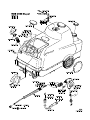
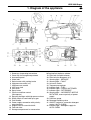
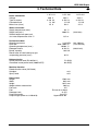
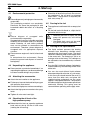
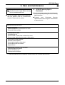
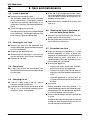
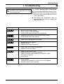
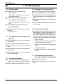
HDS 2000 Super www.kaercher.com 5.956- 535 A 2009680 (11/04) Lesen Sie vor der Inbetriebnahme diese Betriebsanleitung und beachten Sie besonders die Sicherheitshinweise für Hochdruckreiniger. Deutsch Seite 4 English Page 17 Veuillez lire attentivement la présente notice dinstructions avant la mise en service et respecter en particulier les «Consignes de sécurité pour nettoyeurs haute pression». 30 Leggere queste istruzioni per luso prima della messa in esercizio facendo particolarmente «Istruzioni per la sicurezza per lidropulitrice ad alta pressione». 43 Lees voor de ingebruikneming deze gebruikshandleiding en neem in het bijzonder de Veiligheidsvoorschriften voor hogedrukreinigers in acht. Français Page Italiano Pagina Nederlands Pagina Please read these operating instructions before starting and strictly observe the Safety Instructions for High Pressure Cleaners. 56 Antes de poner en marcha el aparato deberá estudiar atentamente las «Advertencias y observaciones relativas a la seguridad para limpiadoras de alta presión». 69 Leia estas instruções de serviço antes da colocação em funcionamento e respeite especialmente as «Indicações de segurança para o limpador de alta pressão». 82 95 Ðñéí èÝóåôå ôç óõóêåõÞ ãéá ðñþôç öïñÜ óå ëåéôïõñãßá, äéáâÜóôå ôéò ðáñïýóåò ïäçãßåò ÷åéñéóìïý êáé ôçñåßôå éäéáßôåñá ôéò Õðïäåßîåéò ãéá ìç÷áíÞìáôá êáèáñéóìïý õøçëÞò ðßåóçò. Side 108 De bedes læse denne driftsvejledning igennem før idrifttagningen i denne forbindelse skal især Sikkerhedsforskrifter for højtryksrenser overholdes. Español Página Português Página ÅëëçíéêÜ Óåëßäá Dansk Norsk Før ibruktaking må bruksanvisningen leses nøye og det må taes hensyn til Sikkerhetsregler for høytrykksvaskere. Side 121 Svenska Läs igenom bruksanvisningen före driftstart och uppmärksamma Säkerhetsanvisningar för högtryckstvättar extra noga. Sida 134 Suomi Sivu 147 Türkçe Sayfa 160 Ðóññêèé Còpaíèöa 173 Lue ennen käyttöönottoa tämä käyttöohje huolellisesti läpi ja kiinnitä erikoista huomiota Korkeapainepesurien turvallisuusohjeitiin. Cihaznz iåletmeye baålamadan önce bu kullanma klavuzunu özenle okuyunuz ve özellikle Yüksek Basnçl Temizleyiciler çin Güvenlik Talimatlar bölümündeki bilgileri dikkat ediniz. Ïepeä ââoäoì aïïapaòa â ýêcïëóaòaöèþ ïpo÷òèòe, ïoæaëóécòa, äaííóþ èícòpóêöèþ è còpoão âûïoëíÿéòe ïpèâeäeííûe â íeé óêaçaíèÿ, ocoáeíío Óêaçaíèÿ ïo òexíèêe áeçoïacíocòè äëÿ aïïapaòa, ècïoëüçóeìoão äëÿ ÷ècòêè âoäoé ïoä âûcoêèì äaâëeíèeì. HDS 2000 Super 1. Diagram of the appliance 1 2 3 4 5 6 7 8 9 10 11 12 12a 13 14 15 16 17 Summary of operating instructions Cover flap for storage compartment Instrument panel Water inlet Swivel caster with parking brake High-pressure outlet (x 2) High-pressure nozzle Unit cover lock Unit cover Spray lance Pressure and flow control (Servopress) Spraying handgun with high-pressure hose Safety catch of hand-held spray gun Push handle Power supply connection with polarityreversing plug Support rails for use with forklift Fuel tank inlet Storage compartment for accessories GB 18 Service/fault indicator window 19 Filler hole for liquid softener 20 Filler hole for detergents (x 2) 21 Warning light – SERVICE 22 Warning light – FAULT 23 Unit main switch 24 Temperature regulator 25 Indicator light – FUEL 26 Indicator light – LIQUID SOFTENER 27 Indicator light – DETERGENT 28 Warning light – INCORRECT MOTOR ROTATION, reverse polarity of power supply 29 Pressure gauge 30 Detergent metering valve 31 ON/OFF switch for automatic detergent control (AUTO-CHEM) 32 Indicator light – detergent supply for AUTO-CHEM 17 HDS 2000 Super GB 1 2 3 4 5 6 7 8 9 10 11 12 13 14 15 16 17 18 19 18 2. Flow-path schematic Water inlet Water cooling, motor 1 Water cooling, motor 2 Water filter Float tank 1 Liquid softener reservoir (DGT) Solenoid valve, DGT Float tank 2 High-pressure pump 1 High-pressure pump 2 Overflow valve Pressure switch, 10 bar Non-return valve Pressure switch, 30 bar Pressure switch, 100 bar Vibration damper Pressure gauge Safety valve Low-water safety device 20 21 22 23 24 25 26 27 28 29 30 31 32 33 34 35 36 37 Vibration damper Continuous-flow heater Burner blower Fuel pump Low-fuel valve Flame monitor Fuel tank Temperature regulator Sealing cap for high-pressure outlet 2 Spraying handgun High-pressure nozzle Dual detergent metering valve Detergent solenoid valve 1 Detergent solenoid valve 2 Detergent level sensor 1 with filter Detergent level sensor 2 with filter Detergent reservoir 1 Detergent reservoir 2 HDS 2000 Super GB 3. Technical Data Power connection Voltage Type of current Connected load Mains fuse (slow) Water connection Supply temperature (max.) Supply rate (min.) Suction height fom open tank at a water temperature of 20 °C Performance data Operating pressure Flow rate Operating temperature (max.) Detergent intake Burner capacity Recoil force of hand-held spray gun at operating pressure (max.) Noise emission Sound pressure level (EN 60704-1) Garanteed sound power level (2000/14/EC) Machine vibration Rated vibration value (ISO 5349) Handgun Spray lance Dimensions Length Width Height Weight without accessories Fuel tank Fuel Detergent tank Pump oil quantity Pump oil type (order no. 6.288-016) 1.071-111 1.071-261 1.071-281 400 3~50 12 25 230 3~50 12 50 420 3~50 12 25 V Hz kW A V Hz kW A 30 °C 2000 l/h V Hz kW A (33,3 l/min) 0,5 m 3-18 850–1800 140/80 0–50 140 MPa l/h °C l/h kW (30–180 bar) (14,2-30 l/min) (0-0,8 l/min) 92 N 75 dB(A) 90 dB(A) m/s² m/s² 1500 mm 834 mm 1015 mm 280 kg 25 l EL fuel oil or diesel 2x 25 l 2x 0,75 l Hypoid SAE 90 19 HDS 2000 Super GB 4. Start-up 4.1 Environmental protection • • • Please dispose of packaging environmentally responsibly. The packaging materials are recyclable. Please do not throw the packaging in with household rubbish but take it to a recycling centre. Please dispose of scrapped units environmentally-responsibly. Scrapped units consist of valuable recyclable materials that should be taken to a recycling centre. Batteries, oil and similar products must not be allowed to contaminate the environment. Therefore, please dispose of scrapped units via appropriate disposal systems. Please contact your dealer immediately if, on unpacking the appliance, you discover damage has been caused during trans-portation. 4.3 Attaching the accessories • • • • • Attach the two handles to the appliance. Fit the spray lance to the hand-held spray gun with pressure flow control. Connect the high-pressure hose accordingly. Attach the high-pressure nozzle to the spray lance. Tighten all union nuts hand-tight. 4.4 Checking the oil level of the high-pressure pump • 20 Before the initial start-up, open the appliance hood and cut the tip off the oil tank cover (venting the oil housing). Check the oil level in the oil tank. Do not start the appliance if the oil level has dropped below “MIN”. Top up the oil as required (see tech. data, chap. 3). 4.5 Pouring in the fuel • • The appliance is delivered with an empty fuel tank. Fill the fuel tank with diesel or a light fuel oil before the initial start-up. – When the fuel tank is empty, the fuel pump will operate dry and will be damaged. – Unsuitable fuels must not be used, e.g. petrol (danger of explosion). 4.6 Pouring in the liquid softener • Please ensure engine oil, fuel oil, diesel and petrol to contaminate the environment. Please protect the ground and dispose of used oil ecologically. 4.2 Unpacking the appliance • • • • The liquid softener prevents the heating element from becoming calcified when operating with hard supply water. The liquid softener is added in drops to the supply water in the water tank. The metering is set to an average value at the factoy. This setting may be adjusted to local conditions by customer service. Pour the RM 110 liquid softener (included in standard delivery) into the filling orifice of the white tank. You can also work without liquid softener when operating with soft water, e.g. rain water. In this case you should remove the small (!) cover from the white tank and place the supplied spring underneath on the cover support. Then replace the cover. This prevents the indicator light on the instrument panel from continually flashing. This spring must be removed when operating with supply water. HDS 2000 Super 4. Start-up 4.7 Connecting the water 4.9 Intended use • • • • See technical data, chap. 3 for connected loads. Attach the supply hose to the appliance and to the water line. The supply hose is not included in standard delivery. If you draw in the water from an open tank, you should – disconnect the water supply from the pump head – unscrew the upper supply hose from the water tank and connect to the pump head. – use a water supply hose which has a minimum diameter of 3/4" and a suction filter. • Until the pump has drawn in the water, you should: • • • GB Use the appliance to clean machines, vehicles, buildings, tools, etc. Clean facades, patios, garden implements, etc. with the high-pressure spray only, i.e. without detergent. We recommend the dirt blaster, a special accessory, for stubborn dirt. If the machine is used at petrol stations or in other hazardous areas, the appropriate safety regulations must be observed. Please ensure waste water containing mineral oil does not contaminate soil, lakes and rivers or the sewerage system. Therefore, please wash engines and underbodies only in appropriate washing installations provided with oil traps. – rotate the pressure and volume control to “MAX”, – close the detergent metering valve. 4.8 Connecting the power • • • • See technical data, chap. 3 for connected loads. The voltage stated on the rating plate must correspond to the voltage of the power source. First, position the appliance switch to “STOP” and then put the electric plug into the socket. If the motor rotates in the wrong direction, the electronic control circuit will switch the motor off after a few seconds. The INCORRECT MOTOR ROTATION warning light illuminates. Disconnect the power input plug. This plug is equipped with a device for reversing polarity. Apply a screwdriver at the prescribed point, press it inwards and rotate both terminals through 180°. Attach the power input plug again. • If you are using an extension lead, it should always be completely unwound from the cable drum and have an adequate cross-section. Mains voltage 10 m 30 m 230 V 6 mm² 10 mm² 400 V 4 mm² 6 mm² 21 HDS 2000 Super GB 5. Operation 5.1 Venting the appliance • • • • Open the water intake. Allow the appliance to run without the highpressure hose until the water emerges without bubbles. 5.3 Adjusting the Operating Pressure and Flow Rate With the servo pressure valve on the hand spray gun – Adjust operating pressure and flow rate (+/–) by rotating the pressure/flow control (infinitely variable). Then connect the high-pressure hose. If the spray lance and high-pressure nozzle have already been fitted to the high-pressure hose, you can vent the appliance as follows: With the hand-held spray gun open, switch the appliance on and off several times at intervals of 10 seconds until the water emerges from the high-pressure hose without bubbles. The two pumps are switched in and out via pressure switches depending on the demand for water. 5.4 Operating with cold water • Switch the appliance switch to “ ”. 5.2 High-pressure nozzle • • The effectiveness of the high-pressure jet depends to a great extent on the spray angle. A 25° fan jet nozzle is usually employed (included in standard delivery). 5.5 Operating with hot water • • Other nozzles are available as accessories. We recommend the following cleaning temperatures: 0° full jet nozzle 30–50 °C for stubborn dirt. max. 60 °C 40° fan jet nozzle for sensitive surfaces. Dirt blaster for thick layers of dirt. Variable angle nozzle with adjustable spray angle • 22 Set the thermostat to the desired temperature. At first always direct the high-pressure jet from a greater distance at the object which is to be cleaned, thereby preventing damage from excessive pressure. 60–90 °C • • for light dirt for dirt which contains protein, e.g. in the food industry for cleaning vehicles, machines Switch the appliance switch to “ ”. If you also increase the operating pressure and flow rate, you also change the water temperature. HDS 2000 Super 5. Operation 5.6 Operating with steam 5.8 Operating with detergent • • • • • When operating temperatures are above 98 °C, the operating pressure must not exceed 32 bar. Thus, the standard high-pressure nozzle must be replaced by a steam nozzle (available as an accessory). We recommend the following cleaning temperatures: up to 140 °C for thawing aggregates, partial cleaning of facades. • Fill the detergent tank. This unit is equipped with an automatic detergent control system. The automatic control can be switched on or off by means of a toggle switch on the instrument panel. Adjust the thermostat to the desired temperature. 100–110 °C for depreservation, dirt containing high levels of grease • GB Rotate the pressure and volume control on the pump head to the lowest value. When you have finished operating the appliance with steam, you should adjust the appliance switch to the “ ” symbol, and run the appliance for approx. 2 minutes with the gun open to allow it to cool down. 5.8.1 Manual detergent control • • The toggle switch for automatic detergent control (AUTO-CHEM) must be set to “ 0 “. Adjust the detergent metering valve for the required concentration and source of detergent, Chem l or Chem ll. When the handgun is opened, the highpressure pumps are switched on and detergent is added to the water. 5.8.2 Automatic detergent control (AUTO-CHEM) 1. Set the toggle switch for automatic detergent control (AUTO-CHEM) to “ l “. 5.7 Operating with two handguns • • • • The unit has two high-pressure outlets, to which it is possible to connect two hand-held spray guns. Unscrew the blanking plug from the second high-pressure outlet and connect another handgun via a high-pressure hose (accessories). The high-pressure nozzle suitable for use with one handgun should be replaced with two nozzles (Nozzle size 25052) The two pumps are switched in and out via pressure switches depending on the demand for water. 2. Adjust the detergent metering valve for the required concentration and source of detergent, Chem l or Chem ll. 3. Open the handgun. The high-pressure pumps start up. If required, detergent can be added to the water as follows: 4. Close the handgun. 5. Open the handgun again immediately after it has been closed (within a max. of 3 sec.) The yellow indicator lamp next to the toggle switch illuminates to show that detergent metering has been switched on. – If the handgun remains closed for longer than 3 seconds before it is opened again, no detergent is added to the water. 6. When the handgun is closed again, the supply of detergent is automatically switched off. The yellow indicator light extinguishes. If detergent is required once more, repeat the procedure outlined in paras. 3, 4, 5, and 6. 23 HDS 2000 Super GB • • 5. Operation In order to protect the environment, we recommend that detergent is used sparingly. Comply with the metering recommendation on the detergent container label. We offer an individual range of detergents and preservatives and therefore guarantee trouble-free operation. Please ask for advice, or request our catalogue or detergent information leaflets. Only those detergents may be used which have been authorized by the manufacturer of the appliance. 5.9 Interrupting operation • • • If you release the trigger of the hand-held spray gun, the appliance switches off. If the trigger is pulled again, the appliance switches on again. If operation is interrupted for more than 30 minutes, the appliance will not switch on when the trigger is pulled (safety shutdown). No maintenance/ fault message appears in the display window. The appliance is ready to use again if you switch the appliance switch off and then on again. Unsuitable detergents can damage the appliance and the object which is to be cleaned. • We recommend the following cleaning method: Step 2: Removing the dirt Warning! Danger of scalding with hot water. After operating it with hot water or steam the unit must be cooled for at least two minutes by operating it with cold water and its open handgun. Spray off the dissolved dirt with the highpressure jet. • When you have finished working with detergent, you should set the detergent metering valve to “0” and rinse the appliance thoroughly with the gun open for approx. 1 minute. • • Step 1: Loosening the dirt Spray on detergent sparingly and allow to react for 1–5 minutes. • 24 5.10 Switching off the appliance • Switch the appliance off and pull the electric plug out of the socket. Close the water intake. Pull the gun trigger until the appliance is depressurized. Secure the gun trigger with the safety catch to prevent the gun from accidentally opening. HDS 2000 Super 6. Care and maintenance Always disconnect the appliance from the electric mains supply before carrying out any maintenance work. • You can arrange a regular safety inspection with your dealer or take out a maintenance contract. Please ask for advice. GB 6.1 SERVICE warning light is illuminated • • If certain maintenance work is required on the basis of elapsed operating hours, this warning light illuminates. Contact your Customer Service representative and arrange for maintenance to be carried out. Required Maintenance Work – Optical inspection – Check high-pressure connections for leaks – Clean fuel tank and filter – – – – Check pump for leaks Change pump oil Clean strainer in water inlet on both float tanks Clean strainer before the low-water safety device – – – – – Decarbonize heater element* Descale heater element* Clean/replace ignition electrodes* Clean/replace Burner nozzles* Adjust burner* – – – – Check pump overflow valve for leaks* Check high-pressure hose* Clean hand spray gun Check pressure damper* * These maintenance tasks should be carried out by the Customer Service only. 25 HDS 2000 Super GB 6. Care and maintenance 6.2 • Visual Inspection Checking the connector cable The connector cable must not be damaged (risk of electricution). A damaged connector cable must be replaced immediately by an authorized Customer Service/qualified electrician. • • • 6.6 Cleaning the Strainer Upstream of the Low-water Safety Device • • 6.3 Cleaning the fuel Tank • • • Dispose of the remaining fuel. • Rinse out the tank thoroughly. If you rinse out the tank with water, allow it to dry completely. Replace the fuel filter. 3 drops per minute are permissible. You should contact customer service if the leakage is more rapid. If the oil is milky (water in the oil), contact customer service immediately. Frost will damage the appliance if it is not drained completely of water. In winter the appliance should be kept in a room which is above freezing point. Otherwise, it is recommended to drain the appliance or rinse it thoroughly with anti-freeze. Draining the appliance – Unscrew the water intake hose and highpressure hose from the appliance. – Unscrew the supply line from the base of the boiler and allow the heating element to drain. – Allow the appliance to run for a max. of 1 minute until the pump and the lines have drained. 6.5 Changing the oil • Rotate an M8 screw into the strainer hole and use it to pull the strainer out. 6.7 Protection from frost 6.4 Pump leaks • Unscrew the high-pressure hose from the pump head at the safety block. Remove the tank from the appliance (first unscrew the handle, appliance hood and cover from the switch box). • • See technical data, chapter 3 for quantity and type of oil. Check the high-pressure hose The high-pressure hose must not be damaged (risk of bursting). A damaged high-pressure hose must be replaced immediately. • When the oil has completely drained, screw the oil drain plug back in and slowly pour in oil up to the “MAX” position on the oil tank (air bubbles must escape). • Anti-freeze During extended down-time periods, it is recommended to pump an anti-freeze through the appliance. This also protects the appliance to a certain degree from corrosion. Unscrew the oil drain plug and dispose of the old oil via an authorized collecting point (protection of the environment). • Observe the following if the unit is connected to a flue: Danger of damage caused by cold air entering through the flue. Disconnect unit from flue at outside temperatures below 0°C. 26 HDS 2000 Super 7. Troubleshooting Always disconnect the appliance from the electric mains supply before carrying out any repair work. 7.1 FAULT warning light is illuminated • • • Display GB This warning light illuminates if there is a fault. When you open the storage compartment cover flap, you will see the electronic display in the view window. The warning light extinguishes when you have corrected the fault and switched the appliance back on. Corrective Action F 1 F 2 F 3 F 4 – Decarbonize heater element* – Readjust burner* – Replace exhaust gas thermostat* F 5 – Check fuses and voltage on all 3 phases.* – Replace air pressure switch* F 6 – Check amount of fuel in tank – Check that burner is functioning correctly* – Check fuel nozzle, ignition electrodes and ignition cable, and replace if required* – Clean burner* F 7 – Motor overload – Winding thermo-protection or thermal relay has triggered – Remove cause of motor overload – Increase water supply volume – Clean strainer in water connection – Clean strainer before the low-water safety device – Replace the reed switch of the low-water safety device* – Clean the low-water safety device* – Repair leak in the high-pressure system * These faults should be corrected by Customer Service or a qualified electrician only. 27 HDS 2000 Super GB 7. Troubleshooting 7.2 Indicator lights 7.5 Detergent is not being drawn in • • • • Indicator light for fuel tank lights up – Refill with fuel. – Check that the fuel level sensor is functioning correctly. • • Indicator light for liquid softener lights up – Refill with RM 110 liquid softener. • – Clean the electrodes in the liquid softener tank. • Clean the detergent suction hose and filter. Clean the metering valve for cleaning agent. Clean the non-return valve on the pump head and the connection for the detergent suction hose. Check all the detergent hoses and connections for leaks. Check whether the detergent solenoid valves have opened. If warning light for detergent illuminates – Refill with detergent. • Indicator light for incorrect motor rotation illuminates – See chapter 4.7. 7.6 Burner does not ignite • 7.3 The appliance does not come up to pressure • • • • • • 28 – Fill the fuel tank. Fill the detergent tank or set the metering valve to zero. – Check that the fuel pump and the fuel solenoid valve function correctly. Vent the appliance (see Operation, chap. 5). – Clean the strainer in the low-water safety device. Clean strainer in water inlet on both float tanks. – Change the fuel filter. Check the water intake volume (see technical data, chap. 3). – Clean the sensor for the electronic flame monitor. Check all the supply lines to the pump for leaks and blockages. 7.4 The pump is knocking • The ignition sparks can be observed through the inspection window in the burner cover. The appliance has a continuous ignition., i.e. even when operating with cold water an ignition spark must be visible. Clean, adjust or replace the ignition electrodes as required. Check all the supply lines to the pump, also the detergent system, for leaks and blockages. Vent the appliance (see Operation, chap. 5). 7.7 The temperature is not reached when operating with hot water/steam • • Set the thermostat higher. Reduce the operating pressure and the flow rate. HDS 2000 Super 8. General Information GB 8.1 Safety equipment 8.3 Spare parts Overflow valve with 2 pressure switches Please note that the use of other than Kärcher spare parts can result in damage and even serious accidents if these parts have not been correctly manufactured, if they do not replace the Kärcher spare part exactly or if they result in unsafe operation of the appliance. When the water flow rate is reduced with the servo compression valve on the hand-held spray gun or with the flow regulator on the pump head, the overflow valve opens and some of the water flows back to the pump suction side. If the gun is completely closed, enabling all of the water to flow back to the pump suction side, the pressure switch located on the overflow valve switches off the pump. If the hand-held spray gun is opened again, the pressure switch located on the cylinder head switches on the pump again. The overflow valve is set and lead-sealed at the factory. Adjustments must only be carried out by customer service. Safety valve The safety valve opens when the pressure switch is defective. The safety valve is set and leadsealed at the factory. Adjustments may only be carried out by customer service. Low-water safety device The low-water safety device prevents the burner from switching on when the water is low. A strainer prevents the safety device from becoming fouled and must be cleaned regularly. 8.2 Accessories Kärcher spare parts guarantee that the appliance can be operated safely and trouble-free. A selection of the most common spare-part numbers are listed at the end of these operating instructions. 8.4 Guarantee The terms of guarantee issued by our competent distribution company are valid in every country. If the appliance malfunctions in any way, we shall rectify the fault free of charge within the period of guarantee, provided the cause can be attributed to faulty material or a manufacturing error. The guarantee will only come into force when your dealer has completely filled out, stamped and signed the enclosed reply card on completion of sale and when you have sent the reply card to the distribution company in your country. In the event of a claim on the guarantee, please consult your dealer with accessories and receipt of purchase or contact your nearest authorized customer service centre. Incorrect, badly fitting or defective accessories impair the function of the appliance and are dangerous. It is advisable to use Kärcher accessories which are made-to-order. Your dealer will be glad to advise you. 29