1
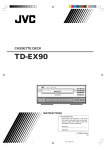
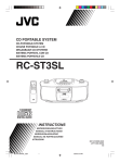
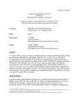
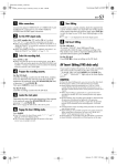
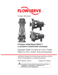
TD-W354B/J
DOUBLE CASSETTE DECK
DOUBLE CASSETTE DECK
TD-W354 B/J
Area suffix
B .................... U.K.
J ..................... U.S.A.
TD-W354 DOUBLE CASSETTE DECK
INPUT LEVEL
5
4
6
COUNTER RESET
3
A
COMPU CAL
2
8
AUTO REVERSE
1
9
MIN
POWER
ON
OFF
PHONES
PITCH CONTROL
MIX LEVEL
DOLBY NR REVERSE A B SYNCHRO DUBBING
B
C
MODE NORM SPEED HIGH SPEED
AUTO REVERSE
POWER
MAX
DECK A
(B version)
B
REC/PLAYBACK
MUSIC SCAN
MUSIC SCAN
Component
MIC
8
1
9
PLAY
PLAY
MIN
PHONES
MAX
PITCH CONTROL
MIX LEVEL
MIC
REC/REC MUTE PAUSE
SLOW
MIN
COUNTER RESET
COMPU CALIBRATION
2
PITCH CONTROL
COMPULINK
REC/REC MUTE PAUSE
FAST
COMPU CAL
7
AUTO REVERSE
MAX
SLOW
STANDBY / ON
PLAYBACK
REC/PLAYBACK
PLAY
PLAY
Component
B
A
MUSIC SCAN
MUSIC SCAN
COMPULINK
INPUT LEVEL
5
4
6
3
COMPU CALIBRATION
PITCH CONTROL
DOLBY B-C NR HX PRO
STANDBY
COUNTER RESET
COUNTER RESET
7
AUTO REVERSE
PLAYBACK
TD-W354 DOUBLE CASSETTE DECK
DOLBY B-C NR HX PRO
STANDBY
FAST
MIN
DOLBY NR REVERSE A B SYNCHRO DUBBING
B
C
MODE NORM SPEED HIGH SPEED
MAX
DECK A
(J version)
INSTRUCTIONS
For Customer Use:
Enter below the Model No. and Serial No.
which are located on the rear of the cabinet.
Retain this information for future reference.
Model No.
Serial No.
a
id8/i10371/ 09/23/99 Page 2
IMPORTANT (In the United Kingdom)
Mains Supply (AC 230 V z, 50 Hz only)
RISK OF ELECTRIC SHOCK
DO NOT OPEN
DO NOT cut off the mains plug from this equipment. If the
plug fitted is not suitable for the power points in your home or
the cable is too short to reach a power point, then obtain an
appropriate safety approved extension lead or consult your
dealer.
CAUTION
‘‘TO REDUCE THE RISK OF ELECTRIC SHOCK
DO NOT REMOVE COVER (OR BACK)
NO USER SERVICEABLE PARTS INSIDE
REFER SERVICING TO QUALIFIED SERVICE PERSONNEL.’’
BE SURE to replace the fuse only with an identical approved
type, as originally fitted and to replace the fuse cover.
If nonetheless the mains plug is cut off ensure to remove the
fuse and dispose of the plug immediately, to avoid a possible
shock hazard by inadvertent connection to the mains supply.
The lightning flash with arrowhead symbol, within
an equilateral triangle, is intended to alert the
user to the presence of uninsulated ‘‘dangerous
voltage’’ within the product’s enclosure that may
be of sufficient magnitude to constitute a risk of
electric shock to persons.
DO NOT make any connection to the terminal which is
marked with the letter E or by the safety earth symbol or
coloured green or green-and-yellow.
The wires in the mains lead on this product are coloured in
accordance with the following code:
The exclamation point within an equilateral
triangle is intended to alert the user to the
presence of important operating and maintenance
(servicing) instructions in the literature
accompanying the appliance.
Blue to N
(Neutral) or Black
Brown to L
(Live) or Red
As these colours may not correspond with the coloured markings identifying the terminals in your plug proceed as follows:
WARNING:
The wire which is coloured blue must be connected to the
terminal which is marked with the letter N or coloured black.
TO REDUCE THE RISK OF FIRE OR ELECTRIC SHOCK,
DO NOT EXPOSE THIS APPLIANCE TO RAIN OR MOISTURE.
The wire which is coloured brown must be connected to the
terminal which is marked with the letter L or coloured red.
IF IN DOUBT-CONSULT A COMPETENT ELECTRICIAN.
Please study this instruction manual carefully before starting
to operate the unit, in order to use the unit correctly. We take
no responsibility for any problems resulting from misuse of
this unit by operating this equipment other than instructed in
this manual.
WARNING (In the United Kingdom)
Pre-recorded tapes, records or discs should not be
re-recorded without the consent of the owners of copyright in
the sound recording and in any copyright musical or literary
work embodied in that recording as this constitutes an
infringement of copyright.
INFORMATION (FOR U.S.A.)
This equipment has been tested and found to comply with the
limits for a Class B digital device, pursuant to Part 15 of the
FCC Rules. These limits are designed to provide reasonable
protection against harmful interference in a residential
installation. This equipment generates, uses, and can radiate
radio frequency energy and, if not installed and used in
accordance with the instructions, may cause harmful
interference to radio communications.
However, there is no guarantee that interference will not occur
in a particular installation. If this equipment does cause harmful
interference to radio or television reception, which can be
–2–
determined by turning the equipment off and on, the user is
encouraged to try to correct the interference by one or more of
the following measures:
- Reorient or relocate the receiving antenna.
- Increase the separation between the equipment and receiver.
- Connect the equipment into an outlet on a circuit different
from that to which the receiver is connected.
- Consult the dealer or an experienced radio/TV technician
for help.
id8/i10371/ 09/23/99 Page 3
INTRODUCTION
Thank you for purchasing a JVC product. Read this instruction
book carefully before operating to be sure of getting optimum
performance and longer service life from the unit.
This product can be combinated with a DDRP (DYNAMICS
DETECTION RECORDING PROCESSOR) system (compact
disc player + cassette deck, etc.) to enable setting the optimum recording level automatically. Refer to these instructions for details.
CONTENTS
Features .................................................................................... 3
Auto reverse operation ............................................................. 3
Cautions .................................................................................... 3
Connections .............................................................................. 5
Cassette loading ....................................................................... 5
Names of parts and their functions .......................................... 6
Playback ................................................................................... 7
Multi music scan ....................................................................... 8
Recording ................................................................................. 8
Compu link control system ..................................................... 11
Dubbing .................................................................................. 12
Maintenance ........................................................................... 13
Troubleshooting ...................................................................... 14
Specifications .......................................................................... 15
AUTO REVERSE OPERATION
The auto reverse operation of this unit turns the tape transport
over to the reverse of forward direction automatically when the
tape reaches its end during recording or playback.
• Because of cassette shell construction, a tape recorded in the
forward direction should be played back in the same direction
to obtain stable sound reproduction.
• During recording, auto reverse can be activated only from the
forward to the reverse direction. For good sound quality and to
avoid accidental erasure of previously recorded material,
always start recording with the side A of the tape facing out.
FEATURES
1.
2.
3.
4.
5.
6.
7.
8.
9.
10.
11.
12.
13.
14.
CAUTIONS
Double auto-reverse mechanism for recording/playback
in deck B and playback in deck A
The COMPU CAL function automatically sets the
record/playback flat frequency characteristics and optimal record/playback tape sensitivity for bringing out
maximum tape performance.
Full logic mechanism
Dolby* HX PRO headroom extension
Dolby B & C noise reduction system
DDRP (Dynamics Detection Recording Processor) compatibility
The DDRP function is possible only when used with a suitable JVC CD player.
2-color FL peak level indicator
Digital tape counter respectively for deck A and deck B
Synchro start (normal-/high-speed) dubbing
Auto tape select mechanism (decks A and B)
Multi music scan mechanism for either direction
‘‘Under License of Staar S.A., Brussels, Belgium’’
PITCH control
Microphone mixing is possible
COMPU LINK-3 compatible
1. Prevention of Electric Shocks, Fire Hazards and Damage
1) Even when the POWER switch is set to STANDBY, a very
small current will flow. To save power and for safety when
not using the unit for an extended period of time, disconnect
the power cord from the household AC outlet. (for the J version)
Set the
POWER switch to the OFF position when not in
use. (for the B version)
2) Do not handle the power cord with wet hands.
3) When unplugging from the wall outlet, always grasp and pull
the plug, not the power cord.
4) Consult your nearest dealer when damage, disconnection, or
contact failure is found with the cord.
5) Do not bend the cord sharply, or pull or twist it.
6) Do not modify the power cord in any manner.
7) Do not remove screws to disassemble the unit and do not
touch anything inside the unit.
8) AC power cord (For the J version only)
The AC power cord of this unit has certain one-way direction
connections to prevent electric shock. Refer to the illustration
for correct connection. (Fig. 1)
* Dolby noise reduction and HX Pro headroom extension
manufactured under license from Dolby Laboratories
Licensing Corporation. HX Pro originated by Bang & Olufsen.
and ‘‘HX PRO’’ are trade* ‘‘DOLBY’’, the double-D symbol
marks of Dolby Laboratories Licensing Corporation.
Fig. 1
COMPU LINK control system is the convenient system using
COMPU LINK-3/SYNCHRO terminals on the rear panel.
(See page 5 and 11.)
(For CANADA)
CAUTION
TO PREVENT ELECTRIC SHOCK, MATCH WIDE BLADE
OF PLUG TO WIDE SLOT, FULLY INSERT.
–3–
id8/i10371/ 03/18/97 Page 4
Side ‘‘A’’
(Pour le CANADA)
ATTENTION
POUR EVITER LES CHOCS ELECTRIQUES, INTRODUIRE
LA LAME LA PLUS LARGE DE LA FICHE DANS LA
BORNE CORRESPONDANTE DE LA PRISE ET POUSSER
JUSQU’AU FOND.
Tab ‘‘B’’
9) Do not insert any metallic objects into the unit.
10) Unplug the power cord when there is a possibility of lightning.
11) If water gets inside the unit, unplug the power cord from the
outlet and consult your dealer.
12) Do not block the ventilation holes of the unit so that heat can
escape. Do not install the unit in a badly ventilated place.
13) Be sure to unplug the power cord from the outlet when going
out or when the unit is not in use for an extended period of
time.
2. Installation
1) Avoid placing the unit on or adjacent to an amplifier, to prevent hum from being produced by some types of amplifiers.
Move the unit to a place not affected by the amplifier. Keep
the unit as far as possible from a TV set.
2) Avoid installing the unit in a location subject to ambient temperatures exceeding 40 °C (104 °F) (e.g. direct sunlight,
near heaters, etc.) or less than 0 °C (32 °F), excessive
humidity, dust or vibrations.
3) If this set is moved suddenly from a cold place (0 °C) to a
warm place, it may not function properly because of moisture
generated inside the unit. The unit will function properly
30 minutes after being moved.
3. Cleaning the cabinet
Never use benzine or thinner for cabinet cleaning as they may
damage the surface finish.
4. Cassette tape
1) Loose tape may become tangled in the tape transport
mechanism. Remove slack by winding the tape with a pencil.
(Fig. 2)
Side ‘‘B’’
Tab ‘‘A’’
Adhesive tape
Fig. 3
4) Do not store cassette tapes where there is a magnetic field
(e.g. near a TV, etc.) or in a place subject to high temperatures or humidity.
5. Auto tape select mechanism (decks A and B)
This deck has an Auto Tape Select mechanism which distinguishes between different types of tape from holes in the
cassette. After the type of tape has been detected, bias and
equalization are set to be suitable for the tape.
• Cassettes with the detection holes:
Metal tape (EQ: 70µs) ........................................ Type IV
CrO2 (chrome) tape (EQ: 70µs) .......................... Type II
•
Cassettes without the detection holes:
Normal tape (EQ: 120µs) ..................................... Type I
Some earlier types of metal and CrO2 (chrome) tapes may
not be provided with the detection holes. Avoid using such
tapes, since correct equalization characteristics cannot be
obtained. Also do not use ferrochrome tapes whose characteristics do not match this unit.
CrO2 tape detection
holes
Fig. 2
Metal tape detection holes
Turn the pencil to tighten the tape.
2) The use of C-120 (120 minutes turn around) or thinner tape
is not recommended, since characteristic deterioration may
occur.
3) To prevent recordings from being erased accidentally,
remove the tab(s) with a screwdriver. Reseal the slots with
adhesive tape to erase and re-record after the tabs have
been broken off.
6. Operations
1) Noise may be generated if the
POWER switch is
switched OFF with the deck set to playback or recording
mode. Before switching the
POWER switch OFF, confirm
that the (stop) button has been pressed. (B version)
2) Many operations of this unit are performed under the control
of a microcomputer. Use the unit only after carefully studying
the descriptions and cautions in each item. If operations are
done incorrectly, the unit may stop functioning correctly. If
this happens, for the J version, unplug the power cord and
for the B version, set the
POWER switch to
OFF, so
that the unit can function correctly.
–4–
id8/i10371/ 09/23/99 Page 5
CONNECTIONS
•
•
•
•
Do not switch the power on until all the connections are completed.
Insert the plugs firmly, or poor contact will result, causing
noise.
When the pin-plug cords are employed, always connect the
white plug to the left channel terminal. This helps to avoid
reversed connections.
When using the Compu Link Control System version 3, do not
connect the power cord to the SWITCHED AC OUTLET of an
amplifier or receiver. In the B version, turn the deck
POWER switch ON. Otherwise, the automatic power on/
STANDBY function cannot be carried out.
2. Remote cable connection for COMPU LINK
• By connecting a remote cable, COMPU LINK functions (automatic power on/STANDBY, automatic source selection, synchronized recording and DDRP recording) can be performed.
In this time the provided pin-plug cords must be also connected.
• When making synchronized recording with a CD player, connect the remote cable to the COMPU LINK-1/SYNCHRO or
COMPU LINK-3/SYNCHRO jacks.
Notes:
1. When making synchronized recordings, only a single deck
should be connected to the amplifier.
2. If a component is not a JVC COMPU LINK component,
bypass it when making the remote cable connections.
3. This deck can be connected with an amplifier and a CD
player which have the COMPU LINK-1/SYNCHRO jacks for
COMPU LINK performance. (See page 11 for details.)
1. Connection to a stereo amplifier
Note:
When installing the deck, be sure to install at a distance from
your amplifier. If they are stacked, noise (hum) may occur.
Stereo amplifier
Pin-plug cords (provided)
Remote cable (provided)
Remote cable (provided with CD player)
CD player
CASSETTE LOADING
1. Press the
(eject) button to open the cassette holder.
2. Load a cassette as shown.
3. Press the cassette holder to close it. Be sure to obtain the
click sound to close the holder securely.
•
Notes for the B version:
• If the
POWER switch is set to OFF while the tape is moving, you might not be able to remove the cassette. If this happens, switch the power on again before attempting to remove
the cassette.
Setting the
POWER switch to OFF during playback or
recording may cause a malfunction. Always stop playback
before setting the
POWER switch to OFF.
A
Load the cassette with the
tape-exposed edge down.
AUTO REVERSE
–5–
id8/i10371/ 09/23/99 Page 6
NAMES OF PARTS AND THEIR FUNCTIONS
1 1
2
3
TD-W354 DOUBLE CASSETTE DECK
4 5
TD-W354 DOUBLE CASSETTE DECK
INPUT LEVEL
5
4
6
3
A
AUTO REVERSE
PITCH CONTROL
A
PLAYBACK
COMPULINK
Component
Component
3
7
2
POWER
(B version)
1
2
3
4
5
6
7
8
ON
PLAY
PLAY
PHONES
9
MIX LEVEL
MIC
PAUSE DUBBING
REC/REC
A MUTE
B SYNCHRO
DOLBY NR REVERSE
MODE NORM SPEED HIGH SPEED
B
C
REC/REC MUTE PAUSE
FAST
MIN
SLOW
MAX
(J version)
FAST
r t
9
0
q
w
e
r
t
y
u
–6–
B
REC/PLAYBACK
MIN
DOLBY NR REVERSE A B SYNCHRO DUBBING
MODE NORM SPEED HIGH SPEED
B
C
MAX
DECK A
e
POWER switch (
ON
OFF) (B version)
POWER switch (On/Standby) (J version)
switch (STANDBY/ON) (B version)
Cassette holder (deck A)
Cassette operation buttons (deck A)
: Press to wind the tape quickly from right to left.
: Press to wind the tape quickly from left to right.
PLAY
: Press to play the tape.
(stop)
: Press to stop the tape.
: Press to change the direction of tape travel.
(direction)
(eject) button (deck A)
Power STANDBY indicator
Lights when in the power standby mode.
COUNTER RESET button (deck A)
Press this button to set the digital counter to ‘‘00 00’’.
Even if the
(STANDBY/ON) or POWER switch is set to
STANDBY, the counter value at that time is stored in
memory.
Indicators
1 DDRP indicator
2 Peak level indicator
These indicators light according to the level of the signal
being recorded or the level of the signal recorded on the
tape.
Note:
0 dB
: IEC (DIN) STANDARD LEVEL (250 nWb/m)
0 VU
: Signal level at 160 nWb/m
3 HX PRO indicator
4 Digital counter
The counter reading increases while the tape is running
from left to right and decreases when it is running from
right to left. In the Multi Music Scan mode when the
(or
) button is pressed, the number of tunes
which will be skipped is displayed.
5 Mechanism mode indicators (deck A)
: This lights when rewinding the tape
from left to right.
: This lights when rewinding the tape
from right to left.
PLAY
: This lights when in the playback.
,
: Indicates the direction of tape travel.
AUTO REVERSE
MAX
PITCH CONTROL
MIC
COMPU CALIBRATION
B
REC/PLAYBACK
PLAY
PLAY
MIN
PHONES
MIX LEVEL
DECK A
OFF
AUTO REVERSE
MUSIC SCAN
MAX
PITCH CONTROL
DOLBY B-C NR HX PRO
COUNTER RESET
COMPU CALIBRATION
8
1
9
SLOW
STANDBY / ON
COMPU CAL
MUSIC SCAN MUSIC SCAN
1
w
7
2
8
MIN
POWER
INPUT LEVEL
5
4
6
AUTO REVERSE
PITCH CONTROL
q
DOLBY B-C NR HX PRO
COUNTER RESET
COMPU CAL COUNTER RESET
MUSIC SCAN
COMPULINK
9 0
8
STANDBY
STANDBY
COUNTER RESET
PLAYBACK
6 7
y
u
i
o p
a
6 Dubbing mode indicators
‘‘DUBBING >’’
: Lights when in the normal-speed dubbing mode.
‘‘DUBBING >>’’ : Lights when in the high-speed dubbing mode.
7 CONT
: Lights when the unit is in the continuous play mode.
8 Mechanism mode indicators (deck B)
PLAY
: Lights when the unit is in the playback
and record modes.
,
: Indicates the direction of tape travel.
REC
: Lights when the unit is in the record
and record-pause modes; blinks during record muting.
: Pause indicator
: This lights when rewinding the tape
from left to right.
: This lights when rewinding the tape
from right to left.
9
: Indicates reverse mode.
COMPU CAL button and indicator
Press this button to automatically set the recording characteristics with the COMPU CAL function. (See page 9.)
COUNTER RESET button (deck B)
(eject) button (deck B)
Cassette holder (deck B)
PHONES jack
Connects headphones (with an impedance of 8 Ω to 1 kΩ).
INPUT LEVEL control
PITCH CONTROL (deck A)
Varies the tape speed in deck A in the range of about ±10%.
However, it cannot change the tape speed in the high-speed
dubbing.
Turning it counterclockwise toward ‘‘SLOW’’ causes the tape
speed to decrease while turning clockwise toward ‘‘FAST’’
causes it to increase. The center click position is for the
standard speed. (See page 8.)
Mixing microphone level control
Adjusts the microphone input level.
MIX MIC jack
Connects a microphone (with an impedance of 600 Ω to
10 kΩ) to this jack.
Sounds from the microphone are monaural.
id8/i10371/ 09/23/99 Page 7
PLAYBACK
8
1
1
2
POWER
POWER
3
ON
STANDBY / ON
OFF
(B version)
(J version)
2
A
4
5
6
7
8
4
9
3
4
DOLBY NR
B
i Cassette operation buttons (deck B)
: Press to wind the tape quickly from right
to left.
: Press to wind the tape quickly from left to
right.
(stop)
: Press to stop the tape. Also press to stop
both decks simultaneously during dubbing.
PLAY
: Press to start playback/recording.
REC/
: Press the PLAY button while pressing
REC MUTE
this button to start recording, and press
to leave an appropriate non-recorded
section. (See page 10.)
PAUSE
: Press to stop the tape temporarily during
recording and playback. Press the PLAY
button to release the pause mode.
(direction) : Press to change the direction of tape
travel.
o DOLBY NR button and indicators
Set to B or C for recording using the Dolby NR system or for
playing back a tape that was recorded using the Dolby NR
system. Each time the button is pressed the NR mode
changes and the indicator lights. (Dolby B NR -> Dolby C NR
-> NR OFF -> Dolby B NR ...)
Set to OFF when the Dolby NR system is not used.
p REVERSE MODE button
Select the single side or full record/playback mode, or the
continuous play mode. Each time the button is pressed the
mode changes. (
->
->
->
...) The current mode
can be checked with the mechanism mode indicator.
: For single-side recording or playback.
: To play or record both sides A and B.
: To play sides A and B continuously.
a A
B SYNCHRO DUBBING buttons
Press to dub from deck A to deck B.
• NORM SPEED : Press to perform normal-speed dubbing.
• HIGH SPEED
: Press to perform high-speed dubbing.
5
REVERSE
MODE
C
6
PLAY
Playback of deck A
Operate in the order of the numbers in the illustration.
1 Turn the power on.
2 Load a prerecorded cassette with side A facing out.
3 Select the side to be played back.
Side A... Forward direction (PLAY
)
Side B... Reverse direction ( PLAY)
4 Press the DOLBY NR button to set the same setting as when
the tape was recorded.
5 Select the REVERSE MODE.
6 Press the PLAY button of deck A to start playback.
• When the deck contains a tape, it can be played back by just
pressing the PLAY button in the B version only when the
POWER switch is set to ON and the
switch is at
STANDBY. In the J version, the tape can be played back by
pressing the PLAY button only when the POWER switch is set
to STANDBY.
Playback of deck B
Perform steps 2 to 6 of the above procedure for deck B.
Microphone mixing during playback
By connecting a microphone, microphone mixing with playback
sound from deck A or deck B is possible.
Continuous play
First press the REVERSE MODE button to set to
.
Load cassette tapes in both decks and press the PLAY button of
the deck to be played first for continuous play of both decks.
• At this time, the CONT indicator lights in the multimode display.
When the tape in the deck which plays first reaches the end of
side B (in the reverse direction), it automatically switches to the
forward direction and enters the standby mode. At the same
time, the other deck starts playback. These operations continue between decks A and B.
• While one deck is playing back, the cassette in the other one
can be replaced. This is convenient for long-time playback of
background music.
Note:
• Use tapes recorded using the same NR mode in decks A and
B.
–7–
id8/i10371/ 09/23/99 Page 8
PITCH CONTROL (deck A)
It is possible to vary the tape speed in deck A in the range of
about ±10% in the playback mode. The center click position is
for the standard tape speed.
RECORDING
Deck B only
Operate in the order of the numbers in the illustration.
• Make sure the safety tab of the cassette has not been broken
off.
MULTI MUSIC SCAN
It should be noted that it may be unlawful to re-record prerecorded tapes, records, or discs without the consent of the
owner of copyright in the sound or video recording, broadcast
or cable programme and in any literary, dramatic, musical, or
artistic work embodied therein.
The multi music scan mechanism of this unit allows you to
quickly locate the beginning of a specific tune (up to 99 tunes
before or after the current tune).
• The multi music scan mechanism functions by detecting nonrecorded sections between tunes (of more than 4–5 sec.).
• The illustration shows the forward direction.
Example of fast forward scan.
•
1
POWER
POWER
PLAY
ON
STANDBY / ON
OFF
(B version)
(J version)
2
MUSIC SCAN
PLAY
A
Procedure
1. Press the
button during playback.
2. When more than 2 tunes are to be skipped, after procedure
1 press the
(or
) button the number of times you
want to skip tunes. The number of tunes to be skipped is
displayed in the counter.
• Relation between Multi Music Scan and REVERSE MODE.
: The multi music scan mechanism operates on one
side of the tape only. If the number set is too high
(more than there are tunes remaining on that side),
the tape stops when the end of the tape is reached.
: It operates continuously through one cycle of the A
and B sides of the tape. If the number set has not
been reached, the tape stops at the end of the B
side. When the head rotates to play side A from B or
B from A, this rotation is counted as one nonrecorded section. When a recorded tune continues
from side A to B, this tune is recorded as two tunes.
In such a case, press the
(or
) button one
extra time.
Notes:
In the following cases, the mechanism may not operate correctly. This is not a malfunction; use the mechanism according
to the type of program.
• Tapes with tunes having long pianissimo passages (very quiet
parts) or non-recorded portions during tunes.
• Tapes with short non-recorded sections.
3
4
B
5
REVERSE
MODE
DOLBY NR
C
6
7
REC/REC MUTE PAUSE
COMPU CAL
8
9
0
INPUT LEVEL
5
4
6
3
2
8
9
0
PLAY
9
MIN
5
6
7
COUNTER RESET
8
1
1
2
3
4
7
MAX
Turn the power on.
Load a cassette for recording.
Press the DOLBY NR button to set to the required setting.
Press the REVERSE MODE button to set to the desired setting.
Select the side to be recorded.
Press the COMPU CAL button, if required. (See page 9.)
Press the PAUSE button and
REC/REC MUTE button
(record-pause mode).
REC and
indicators light.
Adjust the recording level. (See page 10.)
Press to ‘‘00 00’’.
Press the PLAY button to start recording.
Notes:
• When the safety tabs are removed from a cassette tape, the
tape cannot be recorded even if you try. Make sure that both
tabs are still in place when performing full recording.
–8–
id8/i10371/ 09/23/99 Page 9
•
When the tape is played or recorded in the reverse direction
(side B), only side B is played back or recorded and then the
tape stops automatically.
•
•
DDRP (Dynamics Detection Recording Processor) recording
DDRP recording is performed with suitable JVC CD players and
the recording level adjustment is performed automatically.
Since recording level adjustment is performed automatically for
different types of tape (normal, CrO2 and metal), the adjustment
of INPUT LEVEL control is not required.
Read the instruction book of your CD player carefully.
Notes:
1. Since COMPU CAL operations record a test tone on tapes,
previously recorded contents will be erased.
2. Using new tapes and cleaning the heads beforehand are
recommended for optimal COMPU CAL operations.
3. Some variance in characteristics exists even with the same
type of tape made by the same manufacturer. Therefore,
when precise settings are desired, performing COMPU CAL
operations for each recording is recommended.
4. To delete contents set with COMPU CAL, simultaneously
press the
REC/REC MUTE and B deck COUNTER
RESET buttons. This deletes the calibration data for the type
of tape currently inserted in the unit. Calibration data for
other tape types is not deleted.
COMPU CALIBRATION (COMPU CAL) FUNCTION
•
•
•
This unit is equipped with a COMPU CAL function which can
automatically set the flat frequency characteristics and optimal
tape sensitivity for each tape in approximately 30 seconds.
Calibration data is retained for each tape type (Type I, II or IV).
Calibration data set with COMPU CAL is retained even if the
power is turned off (or the power cord is unplugged), and the
previous calibration data for the same type of tape as the new
tape is recalled each time tapes are changed.
Performing COMPU CAL operations again replaces existing
data with the new data.
COMPU CAL operation
•
•
•
Insert the tape to be recorded and press the COMPU CAL button. During the operation, ‘‘C’’ → ‘‘CA’’ → ‘‘CAL’’ is displayed in
the tape counter. When the operation finishes, the tape returns
to its starting position, and the COMPU CAL indicator lights.
COMPU CALIBRATION is now finished.
Pressing the (stop) button part-way will interrupt the operations.
To recalibrate the unit, press the COMPU CAL button and wait
for the COMPU CAL indicator to go out. Then, press the
COMPU CAL button again.
Note:
If the tape is near its end, it will automatically stop and an error
will be generated during operation. Therefore, be sure to check
the time remaining on the tape (more than 2 minutes in the play
mode) before starting the operations.
COMPU CAL Errors
•
•
When an error occurs or when COMPU CAL operations are
interrupted, calibration data cannot be stored in the memory. If
settings were previously performed, the previous setting values are retained.
After confirming items 1) to 3) above and stopping the error
indication if there are no problems, even tapes which experience errors can be recorded on using either 1 the unit’s preset values or 2 previous setting values. (These are the values
obtained by opening and closing the cassette holder one time.)
* Preset value: a standard value corresponding to each type of
tape, which allows normal recording. (The preset value condition is in effect when the
COMPU CAL indicator is unlit.)
When the COMPU CAL indicator flashes, this indicates a
COMPU CAL error.
Press the (stop) button to stop the error indication.
Care should be taken for the following items as they are the
cause of errors.
1) Dirty heads
-Clean the heads.
2) Scratches on the tape surface
-Replace with an undamaged tape.
3) When the tape ends part-way through the operations
-Change the tape position.
4) In rare cases, tapes may have characteristics which fall outside the COMPU CAL setting range.
–9–
id8/i10371/ 09/23/99 Page 10
MICROPHONE MIXING DURING RECORDING
B. To leave non-recorded sections of more than 4–5 seconds
REC/REC MUTE button pressed continu1. Keep the
ously as long as you want to make a non-recorded section. By releasing the finger from the button after the
above operation, the unit enters the record-pause mode.
2. Press the PLAY button to start recording again.
By connecting a microphone, microphone mixing during recording is possible by following the recording procedure. Adjust the
microphone input level by setting the record-pause mode and
observing the peak level indicators.
• When the record-pause mode is set and the INPUT LEVEL
control is set to MIN, sounds are output only from the microphone, and it can be used as a public address system.
C. To leave non-recorded section of less than 4-seconds
When the undesired section comes during recording....
After the
REC/REC MUTE button is pressed, press the
PLAY button before the unit enters the pause mode to start
recording again, or press the PAUSE button to enter the
record-pause mode.
• The peak level indicator lights even during record muting
according to the input level which can be heard from the
speakers or headphones so that recording can be resumed at
the exact point on the tape.
RECORDING LEVEL ADJUSTMENT
Adjust the recording level while observing the peak level indicator indication.
For example:
With metal tape
ERASING
When recording on a prerecorded tape, the previous recording
is automatically erased and only the new program is recorded
on the tape.
To erase a tape without making a new recording...
Follow the section ‘‘RECORDING’’ but in step 8, set the INPUT
LEVEL control to MIN.
Because of metal tape’s higher saturation level, it is OK that ‘‘+
2’’ lights occasionally.
With normal or chrome tape
DOLBY NR and DOLBY HX PRO
Dolby NR System
To reduce the hiss inherent in tape recording, use the Dolby NR
System when making recordings. When listening to a tape
recorded with the Dolby NR System, press the DOLBY NR button to set to B or C according to the system selected in the
recording mode.
It is OK that ‘‘+ 0’’ lights occasionally.
•
•
•
When the recording level is too low, the hiss noise inherent in
the tape will be conspicuous.
When the recording level is too high, exceeding the saturation
level, the recording will contain cracking noise and will be distorted.
If ‘‘+ 4’’ lights too often because the recording level is too high,
the recorded sound may be distorted and seem to be breaking
up. If only ‘‘0’’ lights infrequently, the level is too low and the
recording may contain tape hiss.
Note:
The sound quality will change if the setting of the DOLBY NR
button is different in recording and playback.
Dolby HX PRO headroom extension
When a source which contains many high-frequency components is recorded, these high-frequency signals have the same
function as bias and therefore, the effective bias current
changes.
This will result in phenomena such as changes in the level of
low-frequency signal and subsequent distortion and reduction of
the high-frequency saturation level.
Dolby HX PRO headroom extension system controls the bias
current so that the effective bias is constant even when there
are fluctuations in the high-frequency components of the input
signal.
This greatly improves the high-frequency saturation level while
reducing the low-frequency signal level variations and distortion.
• The dynamic sound recorded with this system sounds the
same even when the tape is played back in a deck that does
not have Dolby HX PRO.
• This system automatically works when in recording; however,
Dolby HX PRO is not a noise reduction system.
It is best to adjust so that the maximum sound level of the
source to be recorded reaches the very limit of the saturation
level of the tape to be used.
The best level varies depending on the type of music and type
of tape so it is better to make a test recording, using FM music,
records, etc.
AUTOMATIC RECORD MUTING (DECK B)
This facility is used to eliminate undesired sections and leave an
appropriate non-recorded section.
A. To leave non-recorded sections of about 4–5 seconds
automatically
1. When the undesired section comes during recording,
press the
REC/REC MUTE button and release it.
2. The REC indicator flashes and a non-recorded section is
made during record muting operation. About 4–5 seconds later, the tape automatically stops, and the unit
enters the record-pause mode.
3. Press the PLAY button to start recording again.
– 10 –
id8/i10371/ 09/23/99 Page 11
COMPU LINK CONTROL SYSTEM
Notes:
• Synchronized recording or DDRP recording stops automatically when the CD player stops playing.
• Synchronized recording does not start except when the recordpause mode is set by simultaneously pressing the
REC/REC MUTE and PAUSE buttons in the stop mode.
• To cancel synchronized recording or DDRP recording, press
the STOP button of the CD player or cassette deck.
• The source is locked to the CD position during synchronized
recording or DDRP recording to avoid accidental stops or
switch-over to another component. To switch over the components, cancel synchronized recording or DDRP recording first.
• The INPUT LEVEL control does not function during DDRP
recording.
The Compu Link Control System controls relative operations
between components automatically and facilitates various
operations.
This is a system originated and developed by JVC for facilitating
various system operations. There are two versions of this system; version 1 and 3. (For version 1 components, ‘‘COMPU
LINK-1/SYNCHRO’’ is marked on the rear panel. For version 3
components, ‘‘COMPU LINK-3/SYNCHRO’’ is marked on the
rear panel. This unit belongs to version 3.)
The version 3 system controls relative functions between this
unit and an amplifier or receiver, in addition to all of the functions
of version 1.
Automatic Power On/STANDBY Function (COMPU LINK-3)
This function is available when an amplifier or receiver having a
COMPU LINK-3/SYNCHRO terminal is connected. For example,
if a deck contains a tape, the deck is turned on automatically
and the tape is played back by only pressing the PLAY button.
When the amplifier or receiver is switched STANDBY, the source
unit is automatically switched STANDBY. (In the B version, it is
necessary to turn the deck
POWER switch ON.)
Automatic Source Selection (COMPU LINK-1, 3)
When the provided remote cables are used for connecting this
unit to other components which have COMPU LINK-1 or
3/SYNCHRO terminals, the switch-over of all system components is possible with simple one-touch of the source selector
button of JVC’s amplifier or receiver.
By doing this, the corresponding component will start playing
automatically.
The source select button of the remote control unit or the activation button of the desired component can be also used for this
purpose. When the components have been switched over, the
previous component will stop playing within five seconds.
Synchronized Recording (COMPU LINK-1, 3)
Synchronized recording refers to the process in which the deck
starts recording in synchronism with the CD player. Perform the
synchronized recording as follows:
1. Set the cassette deck to the record-pause mode in accordance with the recording procedures on page 8.
2. If you want the programmed recording, program the desired
tunes in any order you wish to hear.
3. Press the PLAY/PAUSE button of the CD player. By so
doing, the cassette deck is placed in the record mode and
synchronized with the CD player for recording. Synchronized
recording thus can be made possible.
DDRP (Dynamics Detection Recording Processor) recording
The DDRP function makes possible fully automatic recording
when used with a suitable JVC CD player. When the DDRP button of a suitable JVC CD player is pressed, the recording level
is first adjusted automatically, then recording starts; it is not necessary to start recording by the normal procedure.
– 11 –
id8/i10371/ 09/23/99 Page 12
DUBBING
•
Synchro dubbing
Operate in the order of the numbers in the illustration.
1
POWER
POWER
ON
•
Dubbing and DOLBY NR button
During dubbing, the same NR mode selected for the playback
cassette is applied to the recording cassette, regardless of the
setting of the NR button.
STANDBY / ON
OFF
(B version)
(J version)
Input level
Recording is performed at the same level as the playback tape
during dubbing regardless of the position of the INPUT LEVEL
control.
2
A
Microphone mixing during dubbing
By connecting a microphone, microphone mixing during dubbing
is possible with the playback sounds from deck A. Be sure to
perform dubbing at normal speed. When performing microphone
mixing during dubbing, use cassettes recorded with NR OFF
mode for the deck A.
3
A
4
5
REVERSE
MODE
6
A B SYNCHRO DUBBING
Before pressing the SYNCHRO DUBBING button
Confirm that deck B is in the stop mode before starting dubbing.
Tape editing
1. Press the
REC/REC MUTE button when finished dubbing
a tune. Deck B automatically enters the record muting mode
and leaves a non-recorded section of about 4-seconds then
enters the record-paused mode.
2. Press the (stop) button of deck A and search for the next
tune you want by using the
,
or PLAY button. Then
stop the cassette just before the beginning of the tune.
3. Press the same SYNCHRO DUBBING button pressed
before the pause again, and dubbing will start.
COUNTER RESET
7
NORM SPEED HIGH SPEED
Notes at dubbing
1. Normal-speed dubbing is recommended to obtain good
sound quality.
2. Television receivers placed close to the deck may cause
interference on the recorded signal when the deck is used in
the high-speed dubbing mode. If this happens, either turn off
the television receiver or use the normal-speed dubbing
mode.
1 Turn the power on.
2 Insert a prerecorded tape with side A facing out into deck A,
and press the
(direction) button to select the travel
direction.
3 Insert the blank tape with side A facing out into deck B, and
press the
(direction) button to select the side to be
recorded.
4 Select the REVERSE MODE.
5 Press to ‘‘00 00’’. (Deck B)
6 Press the SYNCHRO DUBBING (NORM or HIGH SPEED)
button to start dubbing.
7 Press the (stop) button of deck B to stop dubbing.
When deck B stops, the dubbing mode is automatically
released.
• Synchro record muting
When deck A stops or enters any mode other than the playback mode during dubbing, deck B enters the record mute
operation automatically and then enters the record-pause
mode.
– 12 –
id8/i10371/ 09/23/99 Page 13
MAINTENANCE
The importance of cleaning
When the tape is moving, magnetic powder and dust naturally
accumulate on the heads, capstan and pinch roller. When they
become too dirty.
• tone quality deteriorates.
• the output sound level drops.
• the previous sound is not erased satisfactorily.
• recordings are not satisfactory.
Because of this, clean the heads, etc. every 10 hours of use so
that optimum recordings will be made.
Demagnetizing the heads
Magnetic objects brought close to the head or using the deck for
a long period of time, results in magnetization of the head, thus
noise occurs. When the noise is excessive, high frequencies on
the recorded tape may be erased.
Demagnetize the heads and other metal parts that come into
contact with the tape every 20–30 hours of use with a head
demagnetizer (available from your audio store).
Cleaning the heads, pinch roller and capstan
Wipe the heads, the capstan, etc. with a cotton swab with its tip
dipped in alcohol. For effective cleaning, use a cleaning kit available from your audio store. After cleaning, be sure that the
cleaning fluid has completely dried before loading a cassette.
Head
demagnetizer
Example: Deck B
Deck B
Capstan
Pinch roller
Deck A
Deck B
Cotton
swab
Playback head
Erase head
Record/playback
head
– 13 –
id8/i10371/ 09/23/99 Page 14
TROUBLESHOOTING
5. Recording cannot be performed.
• Are the safety tabs of cassette tape broken?
• Are all connections properly and securely made?
• Is the head section dirty?
6. Previous recording is not completely erased.
• Is the erase head dirty?
7. Since tape speed is irregular, wow and flutter occur.
• Is the pinch roller or capstan dirty?
• Is the tape rewound too tight?
8. MUSIC SCAN operation does not function properly.
• Are the non-recorded sections too short (3 sec. or less),
or do they contain high level noise or hum?
What appears to be trouble is not always real trouble. Make
sure first....
1. Cassette cannot be loaded.
• Is the cassette positioned correctly?
2. When PLAY button is pressed, tape does not move.
• Is the tape too loosely wound?
3. Tape runs, but no sound is heard.
• Are all connections properly and securely made?
• Is the MONITOR switch of the stereo amplifier set to the
TAPE position?
• Is the VOLUME control of the stereo amplifier set to MIN?
4. Sound quality is poor.
• Is the DOLBY NR button set to the right setting?
• Is the head section dirty?
• Is the record/playback head magnetized?
• Is the tape worn out?
– 14 –
id8/i10371/ 09/23/99 Page 15
SPECIFICATIONS
Type
Track system
Tape speed
Frequency
response
S/N ratio
Improvement of
MOL
Wow and flutter
Channel
separation
Crosstalk
Harmonic
distortion
Heads
Motors
: Electric governed DC motor for capstan
x1
DC motor for reel x 1
DC motor for mechanism drive x 1
(For both decks A and B)
Fast forward/rewind : Approx. 110 sec. with C-60 cassette
time
Input terminals
LINE IN
: Input sensitivity; 80 mV (0 VU)
(x 1 circuit)
Input impedance; 50 kΩ
MIC x 1
: Input sensitivity; 0.4m V (–68dBV)
(Monaural)
(0 VU)
Matching impedance; 600 Ω z 10 kΩ
Output terminals
LINE OUT
: Output level; 300 mV (0 VU)
(x 1 circuit)
Output impedance; 5 kΩ
PHONES x 1
: Output level; 0.3 mW/8 Ω (0 VU)
Matching impedance 8 Ω–1 kΩ
Other terminals
: COMPU LINK-3/SYNCHRO x 2
Power
requirement
: AC 230 V, 50 Hz (B version)
AC 120 V, 60 Hz (J version)
Power
consumption
: With power on 17 W
With power standby 4.0 W
Dimensions
: 435 x 139 x 331 mm
(W x H x D)
(17-3/16’’ x 5-1/2’’ x 13-1/16’’)
Mass
: 5.1 kg (11.3 lbs.) (B version)
5.0 kg (11.1 lbs.) (J version)
Accessories
: Pin plug cord ....................................... 2
Remote cable ...................................... 1
: Double cassette deck
: 4-track, 2-channel
: 4.8 cm/sec (1-7/8 inch/sec) (Normal)
9.5 cm/sec (3-3/4 inch/sec) (High)
: (–20 dB recording)
Type IV tape ; 20–17,000 Hz
30–16,000 Hz (±3dB)
Type II tape ; 20–16,000 Hz
30–15,000 Hz (±3dB)
Type I tape ; 20–16,000 Hz
30–15,000 Hz (±3dB)
: 58 dB (S = 315 Hz, k3 = 3%,
N = A-weighted, Type IV tape)
The S/N is improved by about 15 dB at
500 Hz and by max. 20 dB at 1 kHz z
10 kHz with Dolby C NR on and
improved by 5 dB at 1 kHz and by
10 dB at above 5 kHz with Dolby B NR
on.
: 4 dB at 10 kHz with Dolby C NR on.
: 0.08% (WRMS), ±0.2% (DIN/IEC)
: 40 dB (1 kHz)
: 60 dB (1 kHz)
: k3; 0.8% (Type IV tape, 315 Hz, 0 VU)
: Deck A; METAPERM head for playback
x1
Deck B; METAPERM head for
recording/playback, 2-gap ferrite head for erasure; combination head x 1
Design and specifications are subject to change without notice.
– 15 –
A4-3A 95.6.5
TD-W354B/J
DOUBLE CASSETTE DECK
VICTOR COMPANY OF JAPAN, LIMITED
© 1997 VICTOR COMPANY OF JAPAN, LIMITED
Printed in Malaysia
VNN2356-671M