1
ENGLISH
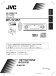
CASSETTE RECEIVER
KS-FX921
!"#$
KS-FX921
‰∑¬
KS-FX921
«‘∑¬ÿ‡§√◊ËÕ߇≈Ëπ‡∑ª
SOUND
ATT
U
R SOURCE F
D
VOL
VOL
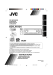
For installation and connections, refer to the separate manual.
!"#$%&'()*+,-./0
°√ÿ≥“¥Ÿ§ŸË¡◊Õ∑’Ë·¬°µË“ßÀ“° „π°“√µ‘¥µ—Èß·≈–°“√‡™◊ËÕ¡µËÕ
INSTRUCTIONS
!"
§”·π–π”
GET0128-001A
[U]
COVER-KS-FX921[U]
3
25/2/03, 11:58 AM
ENGLISH
How to reset your unit
After detaching the control panel, press the reset button on the panel holder using a ball-point pen
or a similar tool.
This will reset the built-in microcomputer.
Note:
Your preset adjustments—such as preset channels or sound adjustments—will also be erased.
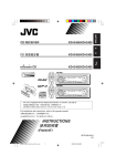
How to use the M (MODE) button
If you press M (MODE), the unit goes into functions mode (“MODE” flashes on the upper part of the
display). While in functions mode, the number buttons work as different function buttons.
• When connecting a JVC MP3-compatible CD changer: The 5/∞ buttons will also work as
+10/–10 buttons after pressing M (MODE).
Ex.: When number button 2 works as MO (monaural) button.
MO (monaural)
indicator lights up.
Time countdown
indicator
To use these buttons for original functions again after pressing M (MODE), wait for 5 seconds
without pressing any of these buttons until the functions mode is cleared (“MODE” disappears from
the display).
• Pressing M (MODE) again also clears the functions mode.
2
EN02-04KS-FX921[U]f.p65
2
3/5/03, 11:45 AM
Thank you for purchasing a JVC product. Please read all instructions carefully before operation,
to ensure your complete understanding and to obtain the best possible performance from the unit.
How to reset your unit ...............................
How to use the M (MODE) button .............
2
2
LOCATION OF THE BUTTONS ............ 4
Control panel .............................................
Remote controller ......................................
Preparing the remote controller ................
4
5
6
BASIC OPERATIONS ....................... 7
Turning on the power ................................
Setting the clock ........................................
7
8
RADIO OPERATIONS ...................... 9
SOUND ADJUSTMENTS ................... 16
Selecting preset sound modes
(C-EQ: custom equalizer) ....................... 16
Adjusting the sound .................................. 17
OTHER MAIN FUNCTIONS ................ 18
Changing the general settings (PSM) ....... 18
Detaching the control panel ...................... 21
CD CHANGER OPERATIONS .............. 22
About MP3 discs ....................................... 22
Playing discs ............................................. 22
Selecting the playback modes .................. 26
Listening to the radio ................................. 9
Storing stations in memory ....................... 10
Tuning in to a preset station ...................... 11
EXTERNAL COMPONENT OPERATIONS ... 27
TAPE OPERATIONS ........................ 12
TROUBLESHOOTING ...................... 28
Listening to a cassette ..............................
Finding the beginning of a tune .................
Other convenient tape functions ...............
Prohibiting cassette ejection .....................
12
13
14
15
BEFORE USE
*For safety....
• Do not raise the volume level too much, as this will
block outside sounds, making driving dangerous.
• Stop the car before performing any complicated
operations.
ENGLISH
CONTENTS
Playing an external component ................. 27
MAINTENANCE ............................. 30
SPECIFICATIONS ........................... 31
*Temperature inside the car....
If you have parked the car for a long time in hot or
cold weather, wait until the temperature in the car
becomes normal before operating the unit.
3
EN02-04KS-FX921[U]f.p65
3
3/5/03, 11:45 AM
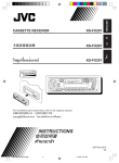
LOCATION OF THE BUTTONS
ENGLISH
Control panel
Display window
d
as
j
1
p
1
2
3
4
5
6
7
8
9
p
q
w
e
r
t
y
u
i
o
;
k
f
l
2 3
/
x
q w e
r
t
4
4
y
h
v
c
4
(standby/on/attenuator) button
SEL (select) button
Control dial
Display window
4
/¢
buttons
5 (up) button
23 (tape direction) button
0 (eject) button
∞ (down) button
Remote sensor
(control panel release) button
EQ (equalizer) button
D (DISP: display) button
• Also functions as SSM buttons when pressed
together with M (MODE) button.
M (MODE) button
• Also functions as SSM buttons when pressed
together with D (DISP) button.
FM/AM button
TAPE (CD-CH: CD changer) button
MO (monaural) button
(Dolby B) button
Number buttons
RPT (repeat) button
RND (random) button
• Functions only when connecting to a CD
changer.
EN02-04KS-FX921[U]f.p65
z
g
u i
5
6 7 89
o
;
Display window
a Disc information indicators
TAG (ID3 Tag),
(folder),
(track/file)
• Lights up only when playing an MP3 disc or a
CD Text on a JVC MP3-compatible CD changer.
s Tape-in indicator
d Main display
f Playback item indicators
(disc)
• Lights up only when connecting to a CD changer.
(folder)
• Lights up only when playing an MP3 disc on a
JVC MP3-compatible CD changer.
g Source/clock display
h RND (random) indicator
• Lights up only when connecting to a CD changer.
j EQ (equalizer) indicator
k Sound mode (C-EQ: custom equalizer)
indicators
ROCK, CLASSIC, POPS, HIP HOP, JAZZ,
USER
l LOUD (loudness) indicator
/
(Dolby B) indicator
z Tuner reception indicators
MO (monaural), ST (stereo)
x MP3 indicator
• Lights up only when playing an MP3 disc on a
JVC MP3-compatible CD changer.
c Volume (or audio) level indicator
Equalizer pattern indicator
v RPT (repeat) indicator
3/6/03, 2:19 PM
Remote controller
SOUND
ATT
U
R SOURCE F
D
VOL
ENGLISH
3 • Selects the preset stations while listening to
the radio.
Each time you press the button, the preset
station number increases, and the selected
station is tuned in.
• While playing an MP3 disc on an MP3compatible CD changer;
– Skips to the previous disc if pressed
briefly.
– Skips to the previous folder if pressed and
held.
Note: While playing a CD on a CD changer, this
always skips to the previous disc.
4 Functions the same as the control dial on the
main unit.
Note: These buttons do not function for the
preferred setting mode adjustment.
VOL
5 Selects the sound mode (C-EQ: custom
equalizer).
Each time you press the button, the sound
mode (C-EQ) changes.
1 • Turns on the unit if pressed when the unit is
turned off.
• Turns off the unit if pressed and held until
“SEE YOU” appears on the display.
• Drops the volume level in a moment if
pressed briefly.
Press again to resume the volume.
2 • Selects the band while listening to the radio.
Each time you press the button, the band
changes.
• Changes the tape direction while listening to
a cassette.
Each time you press the button, the tape
direction changes alternately.
• While playing an MP3 disc on an MP3compatible CD changer;
– Skips to the next disc if pressed briefly.
– Skips to the next folder if pressed and
held.
Note: While playing a CD on a CD changer, this
always skips to the next disc.
6 Selects the source.
Each time you press the button, the source
changes.
7 • Searches for stations while listening to the
radio.
• Functions as the fast-forward or rewind
buttons if pressed and held while listening to
a cassette.
To release this operation, press button 2 to
resume playback.
• Functions as Multi Music Scan buttons if
pressed while listening to a cassette.
To release this operation, press button 2 to
resume playback.
• Fast-forwards or reverses the track/file if
pressed and held while listening to the CD
changer.
• Skips to the beginning of the next track/file
or goes back to the beginning of the current
(or previous) tracks/files if pressed briefly
while listening to the CD changer.
5
EN05-06KS-FX921[U]f.p65
5
3/5/03, 11:45 AM
ENGLISH
Preparing the remote
controller
Before using the remote controller:
• Aim the remote controller directly at the remote
sensor on the main unit. Make sure there is no
obstacle in between.
Remote sensor
• Do not expose the remote sensor to strong
light (direct sunlight or artificial lighting).
Installing the battery
When the controllable range or effectiveness of
the remote controller decreases, replace the
battery.
1. Remove the battery holder.
1) Push out the battery holder in the direction
indicated by the arrow using a ball-point
pen or a similar tool.
2) Remove the battery holder.
3. Return the battery holder.
Insert again the battery holder by pushing it
until you hear a clicking sound.
(back side)
WARNING:
• Store the battery in a place where children
cannot reach.
If a child accidentally swallows the battery,
consult a doctor immediately.
• Do not recharge, short, disassemble, or heat the
battery or dispose of it in a fire.
Doing any of these things may cause the battery
to give off heat, crack, or start a fire.
• Do not leave the battery with other metallic
materials.
Doing this may cause the battery to give off
heat, crack, or start a fire.
• When throwing away or saving the battery,
wrap it in tape and insulate; otherwise, the
battery may start to give off heat, crack, or start
a fire.
• Do not poke the battery with tweezers or similar
tools.
Doing this may cause the battery to give off
heat, crack, or start a fire.
(back side)
CAUTION:
DO NOT leave the remote controller in a place
(such as dashboards) exposed to direct sunlight for
a long time. Otherwise, it may be damaged.
2. Place the battery.
Slide the battery into the holder with the +
side facing upwards so that the battery is
fixed in the holder.
Lithium coin
battery (product
number: CR2025)
6
EN05-06KS-FX921[U]f.p65
6
3/5/03, 11:45 AM
ENGLISH
BASIC OPERATIONS
3
1
2
Turning on the power
1
Turn on the power.
Note on One-Touch Operation:
When you select a source in step 2 below, the
power automatically comes on. You do not have
to press this button to turn on the power.
2
Volume level appears.
Volume (or audio) level indicator
(see page 19)
4
Adjust the sound as you want. (See
pages 16 and 17.)
Select the source.
To drop the volume in a moment
To operate the tuner (FM or AM),
see pages 9 – 11.
To play a tape,
see pages 12 – 15.
To operate the CD changer,
see pages 22 – 26.
To operate the external component
(LINE IN), see page 27.
3
Adjust the volume.
Press
briefly while listening to any
source. “ATT” starts flashing on the display, and
the volume level will drop in a moment.
To resume the previous volume level, press the
button briefly again.
• If you turn the control dial, you can also restore
the sound.
To turn off the power
Press and hold
for more than one
second.
“SEE YOU” appears, then the unit turns off.
To increase the volume
To decrease the volume
7
EN07-08KS-FX921[U]f.p65
7
3/5/03, 11:46 AM
ENGLISH
4
Setting the clock
1
Finish the setting.
Press and hold SEL (select) for more
than 2 seconds so that one of the
PSM items appears on the display.
(PSM: see page 18.)
Note:
To show the clock time on the display, see page 19.
2
Set the hour.
1 Select “CLOCK H” (hour) if not shown on
the display.
2 Adjust the hour.
1
To check other information during play, press
D (DISP).
2
Each time you press the button, the other
information will be shown on the upper part of
the display. (See page 19 for details.)
• Pressing D (DISP) with the unit turned off will
show the clock time for about 5 seconds.
3
Set the minute.
1 Select “CLOCK M” (minute).
2 Adjust the minute.
1
2
8
EN07-08KS-FX921[U]f.p65
8
3/5/03, 11:46 AM
ENGLISH
RADIO OPERATIONS
Listening to the radio
You can use either automatic searching or manual
searching to tune in to a particular station.
Searching a station automatically:
Auto search
1
Select the band (FM1 – 3, AM).
To stop searching before a station is received,
press the same button you have pressed for
searching.
Searching a station manually:
Manual search
1
Each time you press the
button, the band changes as
follows:
Each time you press the
button, the band changes as
follows:
FM 1
(F1)
FM 2
(F2)
FM 3
(F3)
FM 1
(F1)
AM
FM 2
(F2)
FM 3
(F3)
AM
Note:
This receiver has three FM bands (FM1, FM2,
FM3). You can use any one of them to listen to an
FM broadcast.
Selected band appears*.
2
Lights up when receiving an FM stereo
broadcast with sufficient signal strength.
Select the band (FM1 – 3, AM).
Press and hold ¢
or 4
until “MANU” (manual) starts
flashing on the display.
* When “CLOCK” is set to “ON” (see page 19),
the current indication will soon change to the
clock time.
Note:
This receiver has three FM bands (FM1, FM2,
FM3). You can use any one of them to listen to an
FM broadcast.
2
Start searching a station.
To search stations of
higher frequencies
To search stations of
lower frequencies
When a station is received, searching stops.
EN09-11KS-FX921[U]f.p65
9
CONTINUED ON THE NEXT PAGE
9
3/5/03, 11:46 AM
ENGLISH
3
Tune in to a station you want while
“MANU” (manual) is flashing.
To tune in to stations
of higher frequencies
To tune in to stations
of lower frequencies
• If you release your finger from the button,
the manual mode automatically turns off
after 5 seconds.
• If you hold down the button, the frequency
keeps changing (in 50 kHz intervals for
FM and 9 kHz for AM) until you release
the button.
Storing stations in memory
You can use one of the following two methods to
store broadcasting stations in memory.
• Automatic preset of FM stations: SSM (Strongstation Sequential Memory)
• Manual preset of both FM and AM stations
FM station automatic preset: SSM
You can preset 6 local FM stations in each FM
band (FM1, FM2, and FM3).
1
Each time you press the
button, the band changes as
follows:
FM 1
(F1)
When an FM stereo broadcast is hard to
receive:
1 Press M (MODE) to enter the
functions mode while listening
to an FM stereo broadcast.
“MODE” flashes on the upper
part of the display.
Select the FM band (FM1 – 3) you
want to store FM stations into.
2
FM 2
(F2)
FM 3
(F3)
AM
Press and hold both buttons for
more than 2 seconds.
2 Press MO (monaural), while
“MODE” is still flashing on the
display, so that the MO
indicator lights up on the
display.
Each time you press the
button, the MO indicator lights
up and goes off alternately.
MO (monaural) indicator
“- -SSM- -” appears, then disappears
when automatic preset is over.
Local FM stations with the strongest signals are
searched and stored automatically in the band
number you have selected (FM1, FM2, or FM3).
These stations are preset in the number buttons
—No.1 (lowest frequency) to No.6 (highest
frequency).
When automatic preset is over, the station stored
in number button 1 will be automatically tuned in.
When the MO indicator is lit on the display, the
sound you hear becomes monaural but the
reception will be improved.
10
EN09-11KS-FX921[U]f.p65
10
3/5/03, 11:46 AM
You can preset up to 6 stations in each band
(FM1, FM2, FM3, and AM) manually.
Ex.: Storing FM station of 92.5 MHz into the
preset number 1 of the FM1 band.
1
Select the band (FM1 – 3, AM) you
want to store stations into (in this
example, FM1).
Each time you press the
button, the band changes as
follows:
FM 1
(F1)
2
FM 2
(F2)
FM 3
(F3)
AM
Tune in to a station (in this example,
of 92.5 MHz).
To tune in to stations
of higher frequencies
Notes:
• A previously preset station is erased when a new
station is stored in the same preset number.
• Preset stations are erased when the power supply to
the memory circuit is interrupted (for example,
during battery replacement). If this occurs, preset
the stations again.
Tuning in to a preset station
You can easily tune in to a preset station.
Remember that you must store stations first. If
you have not stored them yet, see “Storing
stations in memory” on pages 10 and 11.
1
Select the band (FM1 – 3, AM).
Each time you press the
button, the band changes as
follows:
To tune in to stations
of lower frequencies
FM 1
(F1)
2
3
Repeat the above procedure to store
other stations into other preset
numbers.
ENGLISH
4
Manual preset
FM 2
(F2)
FM 3
(F3)
AM
Select the number (1 – 6) for the
preset station you want.
Press and hold the number button
(in this example, 1) for more than
2 seconds.
Note:
You can also use the 5 (up) or ∞ (down) button on
the unit to select the next or previous preset stations.
Each time you press the 5 (up) or ∞ (down) button,
the next or previous preset station is tuned in.
Selected band/preset number
and “MEMO” (memory) appear
alternately for a while.
11
EN09-11KS-FX921[U]f.p65
11
3/5/03, 11:46 AM
ENGLISH
TAPE OPERATIONS
Listening to a cassette
You can play back type I (normal) tapes.
1
Open the control panel.
Note on One-Touch Operation:
When a cassette is already in the cassette
compartment, pressing TAPE (CD-CH) turns on
the unit and starts tape play automatically.
2
Insert a cassette into the cassette
compartment.
The unit turns on and
tape play starts
automatically.
3
Close the control panel by hand.
To stop play and eject the cassette
Press 0.
Tape play stops, the control panel flips down. The
cassette automatically ejects from the cassette
compartment. The source changes to the
previously selected one.
If you change the source, tape play also stops
(without ejecting the cassette this time).
• You can also eject the cassette by pressing 0
while the unit is turned off.
To fast-forward and rewind a tape
Press and hold ¢
for
more than one second to
fast-forward the tape.
When the tape reaches its
end, the tape is reversed and
playback starts from the
beginning of the other side.
Press and hold 4
for more than one
second to rewind the tape.
When the tape reaches its end, playback of the
same side starts.
To stop fast-forward and rewind at any
position on the tape, press 23.
Tape play starts from that position on the tape.
4
Select the tape direction.
Each time you press 23,
the tape direction changes
alternately between forward
(
) and reverse
(
).
Notes:
• When one side of the tape reaches its end during
play, the other side of the tape automatically starts
playing. (Auto Reverse)
• When the tape reaches its end while fastforwarding, the tape direction will be changed
automatically.
12
EN12-15KS-FX921[U]f.p65
12
3/5/03, 11:46 AM
ENGLISH
To play back tapes recorded with the
Dolby B NR*
1 Press M (MODE) to enter the functions
mode while listening to a tape.
“MODE” flashes on the upper part of the
display.
2 Press
(Dolby B), while “MODE” is still
flashing on the display so that the
(Dolby B) indicator lights up.
“DOLBY B” also appears on the display for
several seconds.
To cancel the Dolby B NR, repeat steps 1
and 2 again so that the
(Dolby B) indicator
goes off.
* Manufactured under license from Dolby
Laboratories.
“Dolby” and the double-D symbol are
trademarks of Dolby Laboratories.
Finding the beginning of a
tune
Multi Music Scan (MMS) allows you to
automatically start playback from the beginning
of a specified tune. You can specify up to 9 tunes
ahead of or before the current tune.
Ex.: When you locate three tunes ahead
of the current tune
Each time you press the buttons, the number
changes up to ±9.
When the beginning of the specified tune is
located, playback starts automatically.
Notes:
• While locating a specified tune:
– If the tape is rewound to its beginning, playback
starts from the beginning of that side.
– If the tape is fast-forwarded to the end, it is
reversed and played from the beginning of the
other side.
• In the following cases, the Multi Music Scan
function may not operate correctly:
– Tapes with tunes having long pianissimo
passages (very quiet parts) or non-recorded
portions between tunes.
– Tapes with short non-recorded sections.
– Tapes with high level of noise or humming
between tunes.
– Tapes with tunes recorded at low recording
levels.
– The Dolby NR setting does not match. For
example, if Dolby B NR is on and the tape was
recorded with no Dolby NR.
During playback
Specify the tune you want to locate (how
many tunes ahead of or before the
current tune).
Press ¢
to locate a
tune ahead of the current
tune on the cassette.
Press 4
to locate a
tune before the current
tune on the cassette.
13
EN12-15KS-FX921[U]f.p65
13
3/5/03, 11:46 AM
ENGLISH
Other convenient tape functions
3
Skipping the blank portions on the tape
You can skip blank portions between the tunes
(Blank Skip).
When this function is turned on, the unit fastforwards (skipping blank portions of 15 seconds
or more), to the next tune and starts playback.
• See also “Changing the general settings
(PSM)” on page 18.
1
2
Turn the control dial clockwise to
select “ON.”
Now Blank Skip is
activated.
4
Finish the setting.
Press and hold SEL (select) for more
than 2 seconds so that one of the
PSM items appears on the display.
(PSM: see page 18.)
Press ¢
or 4
“B.SKIP” (blank skip).
To cancel Blank Skip, repeat the same procedure
and select “OFF” in step 3 by turning the control
dial counterclockwise.
to select
14
EN12-15KS-FX921[U]f.p65
14
3/5/03, 11:46 AM
You can play the current tune repeatedly
(Repeat Play).
Prohibiting cassette ejection
You can prohibit cassette ejection and lock a
cassette in the cassette compartment.
1 Press M (MODE) to enter the
functions mode while playing a
tune you want to hear over again
on a cassette.
“MODE” flashes on the upper
part of the display.
2 Press RPT (repeat), while
“MODE” is still on the display, so
that “REPEAT” appears on the
display.
Lights up when Repeat Play is turned on.
When the tune has been played, the tape is
automatically rewound to the beginning of that
tune and the same tune will be played again.
ENGLISH
Playing the current tune repeatedly
While pressing TAPE (CD-CH), press and
hold
for more than 2 seconds.
“NO EJECT” flashes on the display for about
5 seconds, and the cassette is locked and
cannot be ejected.
To cancel the prohibition and unlock the
cassette
While pressing TAPE (CD-CH), press and hold
again for more than 2 seconds.
“EJECT OK” flashes on the display for about
5 seconds, and the cassette is unlocked.
To cancel Repeat Play, repeat steps 1 and 2
again so that the RPT indicator goes off.
Note:
In the following cases, Blank Skip and Repeat Play
may not operate correctly:
– Tapes with tunes having long pianissimo passages
(very quiet parts) or non-recorded portions during
tunes.
– Tapes with short non-recorded sections.
– Tapes with high level noise or humming between
tunes.
– Tapes with tunes recorded at low recording levels.
– The Dolby NR setting does not match. For example,
if Dolby B NR is on and the tape was recorded with
no Dolby NR.
Note:
If you press 0 while cassette ejection is prohibited,
the control panel flips down, but the cassette
continues to play and cannot be ejected.
15
EN12-15KS-FX921[U]f.p65
15
3/5/03, 11:46 AM
ENGLISH
SOUND ADJUSTMENTS
Selecting preset sound modes
(C-EQ: custom equalizer)
You can select a preset sound mode (C-EQ:
custom equalizer) suitable to the music genre.
Select the sound mode you want.
When you press the button once,
the last selected sound mode is
recalled and applied to the
current source.
Sound mode indicator flashes.
Ex.: If you have selected “USER” previously
Indication
For:
Preset values
BAS
ROCK
JAZZ
HIP HOP
(Flat sound)
00
00
OFF
ROCK
Rock or
disco music
+03
+01
ON
CLASSIC
Classical
music
+01
–02
OFF
POPS
Light music
+04
+01
OFF
HIP HOP
Funk or rap
music
+02
00
ON
JAZZ
Jazz music
+02
+03
OFF
Note:
You can adjust each sound mode to your preference.
Once you make an adjustment, it is automatically
stored for the currently selected sound mode. See
“Adjusting the sound” on page 17.
CLASSIC
POPS
Sound mode indicator flashes.
Ex.: When you select “ROCK”
16
EN16-17KS-FX921[U]f.p65
16
LOUD
USER
Then, each time you press the
button, the sound modes change
as follows:
USER
TRE
3/5/03, 11:47 AM
2
You can adjust the sound characteristics to your
preference.
1
To increase the level or
turn on the loudness
To decrease the level or
turn off the loudness
Select the item you want to adjust.
Each time you press the
button, the adjustable items
change as follows:
BAS
TRE
(bass)
(treble)
Adjust the setting.
ENGLISH
Adjusting the sound
FAD
(fader)
VOL
LOUD
BAL
(volume)
(loudness)
(balance)
Equalization pattern changes
as you adjust the bass or treble.
Ex. 1: When you adjust “TRE” (treble)
Indication
To do:
Range
BAS*1
Adjust the bass.
–06 (min.)
|
+06 (max.)
TRE*1
Adjust the treble.
–06 (min.)
|
+06 (max.)
FAD*2
Adjust the front
and rear speaker
balance.
R06 (Rear only)
|
F06 (Front only)
BAL
Adjust the left
and right speaker
balance.
L06 (Left only)
|
R06 (Right only)
LOUD*1
Boost low and high
frequencies to
LOUD ON
produce a well|
balanced sound
LOUD OFF
at low volume level.
VOL*3
Adjust the volume.
Ex. 2: When you turn on the loudness
3
Repeat steps 1 and 2 to adjust the
other items.
To reset each sound mode to the factory
settings, repeat the same procedure and
reassign the preset values listed in the table on
page 16.
00 (min.)
|
50 (max.)
*1 When you adjust the bass, treble, or loudness, the
adjustment you have made is stored for the
currently selected sound mode (C-EQ) including
“USER.”
*2 If you are using a two-speaker system, set the fader
level to “00.”
*3 Normally the control dial works as the volume
control. So you do not have to select “VOL” to
adjust the volume level.
17
EN16-17KS-FX921[U]f.p65
17
3/5/03, 11:47 AM
ENGLISH
OTHER MAIN FUNCTIONS
3
Changing the general settings
(PSM)
Adjust the PSM item selected.
You can change the items listed in the table
below by using the PSM (Preferred Setting
Mode) control.
Basic Procedure
1
2
Press and hold SEL (select) for more
than 2 seconds so that one of the
PSM items appears on the display.
(See the table below.)
4
5
Repeat steps 2 and 3 to adjust the
other PSM items if necessary.
Finish the setting.
Select the PSM item you want to
adjust.
Preferred Setting Mode (PSM) items
• For detailed operations of each PSM items, refer to the pages listed in the table.
Factory-preset
Indications
Selectable values/items
settings
See
page
CLOCK H
Hour adjustment
1 – 12
1 (1:00)
8
CLOCK M
Minute adjustment
00 – 59
00 (1:00)
8
CLOCK
Clock display
ON
19
AUDIO 2
19
AUTO
19
OFF
19
OFF
14
ONCE
20
LEVEL
OFF
ON
AUDIO 1
Level meter
AUDIO 2
OFF
DIMMER
Dimmer mode
AUTO
OFF
ON
TEL
Telephone muting
B.SKIP
Blank skip
SCROLL
Scroll mode
OFF
MUTING 1
MUTING 2
OFF
ON
ONCE
AUTO
OFF
EXT IN*
External component
TAG DISP
Tag display
CHANGER
LINE IN
CHANGER
20
TAG OFF
TAG ON
TAG ON
20
* Displayed only when one of the following sources is selected—FM, AM, and TAPE.
18
EN18-21KS-FX921[U]f.p65
18
3/5/03, 4:42 PM
To select the level meter—LEVEL
You can set the clock to be shown on the display
when the unit is turned on.
When shipped from the factory, the clock is set to
be shown on the display.
You can select the level meter display according
to your preference.
When shipped from the factory, “AUDIO 2” is
selected.
• ON:
• OFF:
• AUDIO 1:
• AUDIO 2:
Clock display is turned on.
Clock display is turned off. When
“OFF” is selected, the other
information (see table below)
appears instead of the clock
display (except when “LINE IN” is
selected as the source).
When CLOCK is set to OFF:
Source
Initial
indication
Tuner
Band
TAPE
or
CD-CH
“TAPE” or
disc number
Pressing D (DISP)
Clock appears for about
5 seconds.
Initial
indication
Shows the audio level indicator.
Alternates “AUDIO 1” setting and
illumination display.
Erases the audio level indicator.
To select the dimmer mode—DIMMER
When you turn on the car headlights, the display
automatically dims (Auto Dimmer).
When shipped from the factory, Auto Dimmer
mode is activated.
• AUTO:
• OFF:
• ON:
Activates Auto Dimmer.
Cancels Auto Dimmer.
Always dims the display.
Note:
Auto Dimmer equipped with this unit may not work
correctly on some vehicles, particularly on those
having a control dial for dimming.
In this case, set the dimmer mode to “ON” or “OFF.”
When CLOCK is set to ON:
Source
• OFF:
ENGLISH
To set the clock display—CLOCK
Pressing D (DISP)
Tuner
Clock
Band appears for about
5 seconds.
TAPE
Clock
“TAPE” appears for
about 5 seconds.
CD-CH
Clock
Disc number and track/
file number appear
alternately each time
you press the button.
To select the telephone muting—TEL
This mode is used when a cellular phone system
is connected. Depending on the phone system
used, select either “MUTING 1” or “MUTING 2,”
whichever mutes the sounds from this unit.
When shipped from the factory, this mode is
deactivated.
• MUTING 1: Selects this if this setting can mute
the sounds while using the cellular
phone.
• MUTING 2: Selects this if this setting can mute
the sounds while using the cellular
phone.
• OFF:
Cancels the telephone muting.
19
EN18-21KS-FX921[U]f.p65
19
3/5/03, 11:47 AM
ENGLISH
To select the scroll mode—SCROLL
You can select the scroll mode for the disc
information (when the entire text cannot be
shown at once).
When shipped from the factory, scroll mode is
set to “ONCE.”
• ONCE:
• AUTO:
• OFF:
Scrolls only once.
Repeats the scroll (5-second
intervals in between).
Cancels scroll mode.
Note:
Even if the scroll mode is set to “OFF,” you can scroll
the display by pressing D (DISP) for more than one
second.
To turn the tag display on or off
—TAG DISP
This function takes effect only when JVC
MP3-compatible CD changer is connected.
An MP3 file can contain file information called
“ID3 Tag” where its album name, performer, track
title, etc. are recorded.
There are two versions—ID3v1 (ID3 Tag version
1) and ID3v2 (ID3 Tag version 2). Only ID3v1 can
be shown.
When shipped from the factory, “TAG ON” is
selected.
• TAG ON:
To select the external component to use
—EXT IN
You can connect the external component to the
CD changer jack on the rear using the Line Input
Adapter KS-U57 (not supplied).
To use the external component as the playback
source through this unit, you need to select
which component—CD changer or external
component—to use.
When shipped from the factory, CD changer is
selected as the external component.
Turns on the ID3 tag display while
playing MP3 files.
• If an MP3 file does not have ID3
tags, folder name and file name
appear.
Note:
If you change the setting from
“TAG OFF” to “TAG ON” while
playing an MP3 file, the tag display
will be activated when the next file
starts playing.
• TAG OFF:
Turns off the ID3 tag display while
playing MP3 files. (Only the folder
name and file name can be
shown.)
• CHANGER: To use the CD changer.
• LINE IN:
To use the external component
other than CD changer.
Note:
For connecting the Line Input Adapter KS-U57 and
the external component, refer to the Installation/
Connection Manual (separate volume).
20
EN18-21KS-FX921[U]f.p65
20
3/5/03, 11:47 AM
You can detach the control panel when leaving
the car.
When detaching or attaching the control panel,
be careful not to damage the connectors on the
back of the control panel and on the panel
holder.
Attaching the control panel
1
Insert the right side of the control
panel into the groove on the panel
holder.
ENGLISH
Detaching the control panel
Detaching the control panel
Before detaching the control panel, be sure to
turn off the power.
1
Unlock the control panel.
2
Pull the control panel out of the unit.
2
Press the left side of the control
panel to fix it to the panel holder.
Note on cleaning the connectors:
If you frequently detach the control panel, the
connectors will deteriorate.
To minimize this possibility, periodically wipe the
connectors with a cotton swab or cloth moistened
with alcohol, being careful not to damage the
connectors.
3
Put the detached control panel into
the provided case.
Connectors
21
EN18-21KS-FX921[U]f.p65
21
3/5/03, 11:47 AM
ENGLISH
CD CHANGER OPERATIONS
We recommend that you use the JVC MP3compatible CD changer with your unit.
About MP3 discs
By using this CD changer, you can play back
your original CD-Rs (Recordable) and CD-RWs
(Rewritable) recorded either in audio CD format
or in MP3 format.
• You can also connect other CH-X series
CD changers (except CH-X99 and CH-X100).
However, they are not compatible with MP3
discs, so you cannot play back MP3 discs.
• You cannot use the KD-MK series CD
changers with this unit.
MP3 “files (tracks)” can be recorded in
“folders”—in PC terminology.
During recording, the files and folders can be
arranged in a way similar to arranging files and
folders of computer data.
“Root” is similar to the root of a tree. Every file
and folder can be linked to and be accessed from
the root.
Before operating your CD changer:
• Refer also to the Instructions supplied with
your CD changer.
• If no discs are in the magazine of the CD
changer or the discs are inserted upside
down, “NO DISC” will appear on the display.
If this happens, remove the magazine and
set the discs correctly.
• If no magazine is loaded in the CD changer,
“NO MAG” appears on the display. If this
happens, insert the magazine in the CD
changer.
• If “RESET 1” – “RESET 8” appears on the
display, something is wrong with the
connection between this unit and the CD
changer. If this happens, check the
connection and make sure the cords are
connected firmly. Then, press the reset
button of the CD changer.
Hierarchy
Level 1
Level 2
Level 3
Level 4
01
02
03
ROOT
05
01
1
6
3
4
10
5
1
11
2
12
Level 5
04
7
8
9
: Folders and their playback order
: MP3 files and their playback order.
Playing discs
Select the CD changer (CD).
TAPE
CD* 1
*1 If you have changed “EXT IN” setting to “LINE
IN” (see page 20), you cannot select the CD
changer.
22
EN22-26KS-FX921[U]f.p65
22
3/5/03, 11:48 AM
Notes:
• When you press TAPE (CD-CH), the power
automatically comes on. You do not have to press
to turn on the power.
• If you change the source, CD changer play also
stops. Next time you select the CD changer as the
source, CD changer play starts from where
playback has been stopped previously.
• When you start playing back a CD Text or an MP3
disc, disc information will automatically appear on
the display. (See the explanation that follows.)
ENGLISH
• When the current disc is an MP3 disc:
Playback starts from the first folder of the
current disc once file check is completed.
Selected disc number*2
To change the display information
While playing back an MP3 file or CD Text, you
can change the disc information shown on the
display.
Each time you press D (DISP), the
display changes to show the
following:
Folder or album name*3
For MP3 discs
(folder) indicator
MP3 indicator
*2 When “CLOCK” is set to “ON” (see page 19),
the current indication will soon change to the
clock time.
*3 If some MP3 files are recorded without being
included in a folder, they are played back first
and “ROOT” appears as the folder name.
• When the current disc is a CD:
Playback starts from the first track of the
current disc.
Selected disc number*4
Current track
Elapsed playing time number
• When “TAG DISP” is set to “TAG ON” (initial
setting: see page 20)
Album name / performer
(folder name*5)
(TAG lights up on the display)
Track title (file name*5)
(TAG lights up on the display)
Elapsed playing time and
Current file number
*5 If an MP3 file does not have ID3 tags, folder name
and file name appear. In this case, the TAG
indicator will not light up on the display.
*4 When “CLOCK” is set to “ON” (see page 19),
the current indication will soon change to the
clock time.
CONTINUED ON THE NEXT PAGE
23
EN22-26KS-FX921[U]f.p65
23
3/5/03, 11:48 AM
ENGLISH
• When “TAG DISP” is set to “TAG OFF”
(
Folder name
lights up on the display)
(
File name
lights up on the display)
Elapsed playing time and
Current file number
To go to a particular disc directly
Press the number button corresponding to the
disc number to start its playback (while the CD
changer is playing).
• To select a disc number from 1 – 6:
Press 1 (7) – 6 (12) briefly.
• To select a disc number from 7 – 12:
Press and hold 1 (7) – 6 (12) for more than
one second.
For CD Text discs
Each time you press the button,
the display changes as follows:
Disc title / performer
(
Track title
lights up on the display)
Elapsed playing time and
Current track number
Notes:
• The display shows up to 8 characters at one time
and scrolls if there are more than 8 characters.
See also “To select the scroll mode—SCROLL” on
page 20.
Some characters or symbols will not be shown (and
be blanked) on the display.
(Ex. “ABCå!d#” ]“ABCA D ”)
• When you press D (DISP) while playing an audio
CD, “NO NAME” appears for the disc title/
performer and the track title.
To fast-forward or reverse the track/file
Press and hold ¢
,
during play, to fast-forward
the track/file.
Press and hold 4
,
during play, to reverse the
track/file.
To go to the next or previous tracks/files
Press ¢
briefly
during play, to skip ahead
to the beginning of the next
track/file.
Each time you press the
button consecutively, the
beginning of the next
tracks/files is located and
played back.
Press 4
briefly during play, to skip back to
the beginning of the current track/file.
Each time you press the button consecutively,
the beginning of the previous tracks/files is
located and played back.
24
EN22-26KS-FX921[U]f.p65
24
3/5/03, 11:48 AM
How to go to the desired track/file quickly
• Ex. 1: To select track/file number 32 while
playing track/file number 6
To go to a track/file quickly
ENGLISH
This operation is only possible when
using JVC MP3-compatible CD changer
(CH-X1500).
1 Press M (MODE) to enter the functions mode
while playing a disc.
“MODE” flashes on the upper
part of the display.
2 Press 5 (up) or ∞ (down) while still in the
Track/file 6
(Three times)
\ 10 \ 20 \ 30
(Twice)
\ 31 \ 32
• Ex. 2 : To select track/file number 8 while
playing track/file number 36
functions mode.
To skip 10 tracks/files*
forwards to the last track/file
(Three times)
Track/file 36 \ 30 \ 20 \ 10
(Twice)
\9\8
To skip 10 tracks/files*
backwards to the first track/file
* The first time you press 5 (up) or ∞ (down)
button, the track/file skips to the nearest
higher or lower track/file with a track/file
number of multiple ten (ex. 10th, 20th, 30th).
Then each time you press the button, you can
skip 10 tracks/files (see “How to go to the
desired track/file quickly” on the right column).
• After the last track/file, the first track/file will
be selected, and vice versa.
Note:
If the current playing disc is an MP3 disc, files are
skipped within the same folder.
To skip to the next or previous folder
(only for MP3 discs)
Press 5 (up) while playing an
MP3 disc, to go to the next
folder.
Each time you press the button
consecutively, the next folder is
located, and the first file in the
folder starts playback.
Press ∞ (down) while playing an MP3 disc, to go
to the previous folder.
Each time you press the button consecutively,
the previous folder is located, and the first file in
the folder starts playback.
25
EN22-26KS-FX921[U]f.p65
25
3/5/03, 11:48 AM
ENGLISH
Selecting the playback modes
To play back tracks/files at random
(Folder Random/Disc Random/Magazine
Random Play)
To play back tracks/files repeatedly
(Track Repeat/Folder Repeat/Disc Repeat
Play)
1 Press M (MODE) to enter the
functions mode during play.
“MODE” flashes on the upper part
of the display.
1 Press M (MODE) to enter the
functions mode during play.
“MODE” flashes on the upper part
of the display.
2 Press RPT (repeat), while “MODE”
is still flashing on the display.
Each time you press the button, the
repeat play mode changes as
follows:
2 Press RND (random), while
“MODE” is still flashing on the
display.
Each time you press the button, the
random play mode changes as
follows:
For MP3 discs:
FLDR RND
DISC RND
Canceled
MAG RND
DISC RND
MAG RND
For MP3 discs:
TRK RPT
FLDR RPT
Canceled
DISC RPT
TRK RPT
DISC RPT
For CDs:
Canceled
For CDs:
Canceled
(disc) and RPT indicators
Ex.: When you select “DISC RPT”
RND indicator
Ex.: When you select “MAG RND”
Note:
The MP3 indicator also lights up if the current playing
disc is an MP3 disc.
Active
indicator
Mode
Note:
The MP3 indicator also lights up if the current playing
disc is an MP3 disc.
Mode
Plays repeatedly
TRK RPT
RPT indicator
lights up.
The current (or
specified) track/
file.
FLDR RPT*
and RPT
indicators
light up.
All files of the
current (or
specified) folder of
the current disc.
and RPT All tracks/files of
indicators light the current (or
up.
specified) disc.
Plays at random
All files of the
current folder, then
files of the next
folder and so on.
Active
indicator
FLDR RND*
and RND
indicators
light up.
DISC RND
and RND All tracks/files of
indicators
the current (or
light up.
specified) disc.
DISC RPT
MAG RND
RND indicator All tracks/files of
lights up.
the inserted discs.
* “FLDR RPT” is only applicable for MP3 discs.
* “FLDR RND” is only applicable for MP3 discs.
26
EN22-26KS-FX921[U]f.p65
26
3/5/03, 11:48 AM
ENGLISH
EXTERNAL COMPONENT OPERATIONS
Playing an external component
2
You can connect the external component to the
CD changer jack on the rear using the Line Input
Adapter KS-U57 (not supplied).
3
Preparations:
• For connecting the Line Input Adapter KS-U57 and
the external component, refer to the Installation/
Connection Manual (separate volume).
• Before operating the external component using the
following procedure, select the external input
correctly. See “To select the external component to
use—EXT IN” on page 20.
1
4
Turn on the connected component
and start playing the source.
Adjust the volume.
Adjust the sound characteristics as
you want. (See pages 16 and 17.)
Select the external component
(LINE IN).
TAPE
LINE IN*
• If “LINE IN”* does not appear on the display,
see page 20 and select the external input
(“LINE IN”).
* Displayed only when one of the following sources is
selected—FM, AM, and TAPE.
Note on One-Touch Operation:
When you press TAPE (CD-CH), the power
automatically comes on. You do not have to press
to turn on the power.
27
EN27-27KS-FX921[U]f.p65
27
3/5/03, 11:48 AM
What appears to be trouble is not always serious. Check the following points before calling a service
center.
Symptoms
Causes
• Sound cannot be heard
from the speakers.
Tape Playback
FM/AM
General
ENGLISH
TROUBLESHOOTING
Remedies
The volume level is set to the
minimum level.
Adjust it to the optimum level.
Connections are incorrect.
Check the cords and
connections.
• This unit does not work at
all.
The built-in microcomputer
may have functioned
incorrectly due to noise, etc.
Press the reset button on the
panel holder after detaching the
control panel. (The clock setting
and preset stations stored in
memory are erased.)
(See page 2.)
• SSM (Strong-station
Sequential Memory)
automatic preset does not
work.
Signals are too weak.
Store stations manually.
• Static noise while listening
to the radio.
The antenna is not connected
firmly.
Connect the antenna firmly.
• A cassette tape cannot be
ejected.
Cassette is locked.
Unlock the cassette.
(See page 15.)
• A cassette tape cannot be
inserted.
You have tried to insert a
cassette in the wrong way.
Insert the cassette with the
exposed tape facing right.
• Cassette tapes become
hot.
This is not a malfunction.
• Tape sound is at very low
level and sound quality is
degraded.
The tape head is dirty.
Clean it with a head cleaning
tape.
28
EN28-31KS-FX921[U]f.p65
28
3/5/03, 11:48 AM
Remedies
No disc is in the magazine.
Insert discs into the
magazine.
Discs are inserted upside down.
Insert discs correctly.
Discs are unplayable.
Insert playable discs.
• “NO MAG” appears on the
display.
No magazine is loaded in the
CD changer.
Insert the magazine.
• “NO FILES” flashes on the
display.
The current disc does not
contain any MP3 files.
Insert a disc that contains
MP3 files.
• MP3 disc is skipped or
cannot be played back.
MP3 files do not have the
extension code—mp3 in their
file names.
Add the extension code
—mp3 to their file names.
MP3 files are not recorded in
the format compliant with ISO
9660 Level 1, Level 2, or Joliet.
Change the disc.
(Record MP3 files using a
compliant application.)
• Noise is generated while
playing an MP3 disc.
The file played back is not an
MP3 file (although it has the
extension code—mp3).
Skip to another file or change
the disc. (Do not add the
extension code—mp3 to nonMP3 files.)
• A longer readout time is
required for an MP3 disc
(“CHECK” keeps flashing on
the display).
Readout time varies due to the
complexity of the folder/file
configuration.
Do not use too many
hierarchies and folders. Also,
do not record any other types
of audio tracks together with
MP3 files.
• MP3 files cannot be played
back as you have intended
them to play.
Playback order is determined
when the files are recorded.
• Elapsed playing time is not
correct for an MP3 disc.
This sometimes occurs during
play. This is caused by how the
files are recorded on the disc.
• “RESET 8” appears on the
display.
This unit is not connected to the
CD changer correctly.
• “RESET 1” – “RESET 7”
appears on the display.
• The CD changer does not
work at all.
ENGLISH
• “NO DISC” appears on the
display.
Causes
CD Changer
Symptoms
Connect this unit and the
CD changer correctly and
press the reset button of the
CD changer.
Press the reset button of the
CD changer.
The built-in microcomputer may
have function incorrectly due to
noise, etc.
Press the reset button on the
panel holder after detaching
the control panel. (The clock
setting and preset stations
stored in memory are
erased.) (See page 2.)
29
EN28-31KS-FX921[U]f.p65
29
3/5/03, 11:48 AM
ENGLISH
MAINTENANCE
This unit requires very little attention, but you will
be able to extend the life of the unit if you follow
the instructions below.
To clean the head
CAUTION:
• Do not play the cassettes with peeling labels;
otherwise, they can damage the unit.
• Tighten tapes to remove slack since loose tape
may become entangled with the mechanism.
• Do not leave a cassette in the cassette
compartment after use, as the tape may become
slack.
The function below is also provided to ensure the
longer life of this unit.
Ignition key-off release/Ignition key-on
play
• Clean the heads after every 10 hours of use
using a wet-type head cleaning tape (available
at an audio store).
When the head becomes dirty, you may realize
the following symptoms:
– Sound quality is reduced.
– Sound level decreases.
– Sound drops out.
• Do not play dirty or dusty tapes.
• Do not touch the highly-polished head with any
metallic or magnetic tools.
• Turning off the ignition key with a cassette in
the compartment automatically releases the
tape from the unit’s tapehead.
• Turning on the ignition key with a cassette in
the compartment starts playback automatically
if you turned off the ignition during tape play.
To keep the tape clean
• Always store the cassettes in their storage
cases after use.
• Do not store cassettes in the following places:
– Subject to direct sunlight
– With high humidity
– At extremely hot temperatures
30
EN28-31KS-FX921[U]f.p65
30
3/5/03, 11:48 AM
AUDIO AMPLIFIER SECTION
CASSETTE DECK SECTION
Maximum Power Output:
Front:
50 W per channel
Rear:
50 W per channel
Continuous Power Output (RMS):
Front:
19 W per channel into 4 Ω, 40 Hz
to 20 000 Hz at no more than
0.8% total harmonic distortion.
Rear:
19 W per channel into 4 Ω, 40 Hz
to 20 000 Hz at no more than
0.8% total harmonic distortion.
Load Impedance: 4 Ω (4 Ω to 8 Ω allowance)
Tone Control Range:
Bass:
±10 dB at 100 Hz
Treble: ±9 dB at 10 kHz
Frequency Response: 40 Hz to 20 000 Hz
Signal-to-Noise Ratio: 70 dB
Line-Out Level/Impedance:
2.0 V/20 kΩ load (250 nWb/m)
Wow & Flutter: 0.11% (WRMS)
Fast-Wind Time: 100 sec. (C-60)
Frequency Response (Dolby B NR OFF):
30 Hz to 16 000 Hz (Normal tape)
Signal-to-Noise Ratio: 56 dB (Normal tape)
(Dolby B NR ON): 65 dB
(Dolby B NR OFF): 56 dB
Stereo Separation: 40 dB
TUNER SECTION
Frequency Range:
FM:
87.5 MHz to 108.0 MHz
AM:
531 kHz to 1 602 kHz
[FM Tuner]
Usable Sensitivity:
11.3 dBf (1.0 µV/75 Ω)
50 dB Quieting Sensitivity:
16.3 dBf (1.8 µV/75 Ω)
Alternate Channel Selectivity (400 kHz):
65 dB
Frequency Response: 40 Hz to 15 000 Hz
Stereo Separation: 35 dB
Capture Ratio: 1.5 dB
ENGLISH
SPECIFICATIONS
GENERAL
Power Requirement:
Operating Voltage: DC 14.4 V
(11 V to 16 V allowance)
Grounding System: Negative ground
Allowable Operating Temperature: 0°C to +40°C
Dimensions (W × H × D):
Installation Size (approx.):
182 mm × 52 mm × 150 mm
Panel Size (approx.):
188 mm × 58 mm × 12 mm
Mass (approx.):
1.5 kg (excluding accessories)
Design and specifications are subject to change
without notice.
[AM Tuner]
Sensitivity: 20 µV
Selectivity: 35 dB
Having TROUBLE with operation?
Please reset your unit
Refer to page of How to reset your unit
31
EN28-31KS-FX921[U]f.p65
31
3/5/03, 11:48 AM
KS-FX921
Installation/Connection Manual
!"#$
°“√µ‘¥µ—Èß/§ŸË¡◊Õ°“√µ‘¥µ—Èß
qOUu²
«ØVOd²
« ULOKFð VÒO²
V
GET0128-002A
J
[U]
ENGLISH
C
0303KKSMDTJEIN
EN, CH, TH, AR
wÐdŽ
‰∑¬
• This unit is designed to operate only on 12 V DC,
NEGATIVE ground electrical systems.
• !"#$% 12V !"#$%&'(
•
INSTALLATION
(IN-DASH MOUNTING)
uKÐUð ‡ qš«œ ® “UN'« VOdð
°“√µ‘¥µ—ßÈ (°“√ª√–°Õ∫·ºßÀπÈ“ª—∑¡Ï‡¢È“)
©…—UOJ
«
• The following illustration shows a typical installation.
However, you should make adjustments
corresponding to your specific car. If you have any
questions or require information regarding
installation kits, consult your JVC car audio dealer
or a company supplying kits.
• !"#$%&' ()*+,-./0123
!"#$%&'()*!+,-./(01
!"#$%&'()*+,- JVC !"#$%&'()*+,-
1
2
3
1
Before mounting: Press
(control panel
release button) to detach the control panel if
already attached.
* When shipped from the factory, the control
panel is packed in the hard case.
2
3
Remove the trim plate.
Remove the sleeve after disengaging the sleeve
locks.
5
6
7
8
9
4
Install the sleeve into the dashboard.
* After the sleeve is correctly installed into the
dashboard, bend the appropriate tabs to hold
the sleeve firmly in place, as illustrated.
5
Fix the mounting bolt to the rear of the unit’s
body and place the rubber cushion over the end
of the bolt.
6
7
8
Do the required electrical connections.
Slide the unit into the sleeve until it is locked.
Attach the trim plate.
Note: Ensure the recessed part is at the bottom.If
not, the control panel will not open completely.
9
•
!"#
!"#$%&'()&*+
!"#$%&'(%)*+,-./0
!"#$%&'()*+,
!"#$
!"#$%&'()*+,#!"#
!"#$%&'()
* !"#$%&'()*+,-./0
!"#$%&'()"*+,-./
!"#$%&&'()*+,-./
!"#$%&'
!"#$%&'
!"#$
=(ª≈¥·ºß§«∫§ÿ¡)
4 µ‘¥µ—Èߪ≈Õ°ÀÿÈ¡≈ß„π·ºßÀπÈ“ª—∑¡Ï
5
6
7
8
*+,-
!"#$
* À≈—ß®“°µ‘¥µ—Èߪ≈Õ°ÀÿÈ¡≈ß„π·ºßÀπÈ“ª—∑¡Ïլ˓ß∂Ÿ°µÈÕß·≈È«
¥—¥√ËÕß„ÀÈ‚§ÈßæÕ¥’∑’˪≈Õ°ÀÿÈ¡®–∂Ÿ°¬÷¥‰«Èլ˓߷πËπÀπ“
(¥—ß¿“æ)
µ‘¥ ≈—°ª√–°Õ∫∫√‘‡«≥¥È“πÀ≈—ß‚§√ߢÕß™ÿ¥ª√–°Õ∫·≈–
«“߬“ß°—π°√–·∑°‰«È∫π Ë«πª≈“¬¢Õß ≈—°
µËÕ “¬‰øµ“¡∑’Ë°”À𥉫È∑—ÈßÀ¡¥
‡≈◊ËÕπ™ÿ¥ª√–°Õ∫≈ß„πª≈Õ°ÀÿÈ¡®π‡¢È“°—π‰¥ÈæÕ¥’
µËÕ·ºËπ‚≈À–¢Õ∫·µËß
À¡“¬‡Àµÿ: ‡«≈“„ ˵ÈÕß·πË„®«Ë“ µ—«≈ÁÕ§Õ¬ŸË∑“ߥȓπ≈Ë“ß
¡‘©–π—Èπ·≈È« ®–‡ª‘¥·ºß§«∫§ÿ¡ÕÕ°‰¡Ë‰¥È∑—ÈßÀ¡¥
WŠu
d¹d% —“®
“d
« jG{« ∫VOd²
« ¡bÐ q³
ÆrJײ
« WŠu
qB# qł« s ©rJײ
«
qš«œ rJײ
« WŠu
l{Ë - ¨lMB*« s s×A
« bMŽ *
Æ‚ËbMB
«
ÆWM¹e
« WŠu
Ÿe½«
qJON
« U²³¦ qB# bFÐ w«u
« qJON
« Ÿe½«
Æw«u
«
ÆÍœuLŽ qJAÐ “UN'« nË« ±
—dCð ÂbŽ s bQ𠨓UN'« nOuð bMŽ ∫WEŠö
s WOHK)« WN'« w# œułu*« “uOH
« ·öð« Ë«
Æ“UN'«
UL ¨w«u
« qJON
«Ë “UN'« 5Ð 5²UJ*« qšœ« ≤
qJON
« U²³¦ qBH
¨qJA
« w# 5³ u¼
Æw«u
«
Æw«u
« qJON
« Ÿe½« ≥
qł« s UUJ*« vKŽ WE#U;« włd¹ ∫WEŠö
Æ“UN'« VOdð bFÐ UIŠô ‰ULF²Ýô«
Æ…—UOJ
« uKÐUð qš«œ w«u
« qJON
« V—
uKÐUð qš«œ UOK w«u
« qJON
« VOdð bFÐ *
qJAÐ WMJ
_« wMŁ« ¨`O×U qJAÐ …—UOJ
«
w# rJ× qJAÐ w«u
« qJON
« XO³¦²
VÝUM
ÆqJA
« w# 5³ u¼ UL ¨`O×B
« ÊUJ*«
“UN'« qJO¼ s WOHK)« WN'UÐ VOd²
« —ULJ X³ÒŁ
Æ—ULJ*« W¹UN½ ‚u# WOÞUD*« …uA(« l{ p
– bFÐË
u¼ UL WÐuKD*« WOzUÐdNJ
« öOUu²
« qLŽ«
Æ ULOKF²
« Ác¼ nKš ÕËdA
qJAÐ X³¦¹ v²Š w«u
« qJON
« qš«œ “UN'« qšœ«
Æ`O×U
ÆWM¹e
« WŠu
VÒ—
ÆqHÝô« w# ·u:« rJI
« Ê« s bQð ∫WEŠö
rJײ
« WŠu
`²Hð ô ·uÝ ¨p
– ·öjÐ
ÆWK U …—uBÐ
ÆrJײ
« WŠu
VÒ—
9 µËÕ‡¢È“°—∫·ºß§«∫§ÿ¡
Attach the control panel.
1
VOd²
« WI¹dÞ w
U²
« w×O{u²
« rÝd
« sO³¹
Ò
•
Ÿu½ oÐUDð ö¹bFð qLŽ pOKŽ V−¹ ¨p
– l ÆWO
U¦*«
Ë« «—UJH²Ý« „UM¼ ÊU «–« ÆUNJK²9 w²
« …—UOJ
«
vłd¹ ¨VOd²
« «Ëœ« ’uBjÐ U uKF* WłUŠ
W—U «—UOJK
WOðuB
« …eNłô« Ÿ“u …—UA²Ý«
Æ «Ëœô« …cN
WŽ“u*« WdA
« Ë« JVC
À¡“¬‡Àµÿ : √–¡—¥√–«—ß„Àȧ—π∫—ߧ—
∫ “¡“√∂„™Èß“π‰¥ÈµËÕ‰ªÀ≈—ß®“°µ‘¥µ—Èß™ÿ¥ª√–°Õ∫·≈È«
%&'()*+,-./
!"
!"#$%&"'
!"#$%&'()
¿“æµ—«Õ¬Ë“ßµËÕ‰ªπ’È· ¥ß∂÷ß°“√µ‘¥µ—Èß·∫∫∑—Ë«‰ª լ˓߉√°Áµ“¡
§ÿ≥§«√ª√—∫·µËß„ÀȇÀ¡“– ¡°—∫√∂¢Õߧÿ≥‡Õß À“°§ÿ≥¡’ª—
≠À“À√◊ÕµÈÕß°“√¢ÈÕ¡Ÿ≈‡°’ˬ«°—∫™ÿ¥µ‘¥µ—Èß °√ÿ≥“ª√÷°…“°—
∫ºŸÈ¢“¬‡§√◊ËÕ߇ ’¬ß√∂¬πµÏ JVC ¢Õß∑Ë“πÀ√◊Õ∫√‘…—
∑∑’Ë®”ÀπË“¬™ÿ¥µ‘¥µ—Èßπ’È∑∑’Ë®”ÀπË“¬™ÿ¥µ‘¥µ—Èßπ’È
‡æ◊ËÕÕÕ°®“°·ºß§«∫§ÿ¡
* ‡¡◊ËÕº≈‘µ¿—≥±Ï∂Ÿ° ËßÕÕ°¡“®“°‚√ßß“π ·ºßÀπÈ“ª—¥®–
∫√√®ÿ‰«È„π≈—ß·¢Áß
2 ∂Õ¥·ºËπ‚≈À–¢Õ∫·µËßÕÕ°
3 ∂Õ¥ª≈Õ°ÀÿÈ¡ÕÕ°À≈—ß®“°ª≈¥∑’Ë≈ÁÕ§ª≈Õ°ÀÿÈ¡ÕÕ°·≈È«
1 ®—∫™ÿ¥ª√–°Õ∫µ—ßÈ ¢÷π
È
À¡“¬‡Àµÿ : ‡¡◊ËÕ§ÿ≥µ—Èß™ÿ¥ª√–°Õ∫¢÷Èπ √–«—
ßլ˓∑”„ÀÈø‘« Ï∫√‘‡«≥ Ë«π∑È“¬‡ ’¬À“¬
2 „ ˧—π∫—ߧ—∫ 2 Õ—π√–À«Ë“ß™ÿ¥ª√–°Õ∫°—∫ª≈Õ°ÀÿÈ¡
(¥—ß¿“æ) ‡æ◊ËÕª≈¥∑’Ë≈ÁÕ§ª≈Õ°ÀÿÈ¡ÕÕ°®“°°—π
3 ª≈¥ª≈Õ°ÀÿÈ¡ÕÕ°
!"#
!"#$%&'()*+,-.
wzUÐdN —UOð WDÝ«uÐ jI# qLFO
“UN'« «c¼ rLUbI
•
ÆV
UÝ i¹—Qð WOzUÐdN WLE½« ¨X
u# ±≤ ¨DC dýU³
1 °ËÕπª√–°Õ∫ °¥ªÿË¡
!" !"#$%&'()*=
!"#$%&
!"#$
* !"#$%&'()*+,&-./0
1 2 3 1 Stand the unit.
Note: When you stand the unit, be careful
not to damage the fuse on the rear.
2 Insert the 2 handles between the unit and the
sleeve, as illustrated, to disengage the sleeve
locks.
3 Remove the sleeve.
Note: Be sure to keep the handles for future
use after installing the unit.
4
!"#$%&
!
™ÿ¥ª√–°Õ∫π’È ‰¥È√—∫°“√ÕÕ°·∫∫¡“‡æ◊ËÕ„™Èß“π°—∫√–∫∫ °√–
· ‰øøÈ“ “¬¥‘π¢—È«≈∫°√–· µ√ß 12 ‚«≈∑Ï
À“°√∂¬πµÏ¢Õߧÿ≥‰¡Ë ‰¥È„™È√–∫∫π’È µÈÕß„™È‡§√◊ËÕß·ª≈ß°√–
· ‰ø™Ë«¬
2
Control panel
!
Trim plate
Dashboard
·ºËπ‚≈À–¢Õ∫·µËß
ÀπÈ“ª—¥
ºßÀπÈ“ª—∑¡Ï
WM¹e
« WŠu
rJײ
«WŠË«
…—UOJ
« uKÐUð
Rubber cushion
!"
¬“ß°—π°√–·∑°
Sleeve
!
Handle
!"
3
18
4
WOÞUD*« …uA(«
4
ª≈Õ°Àÿ¡È
53
w«u
« qJON
«
m
m
5
7
§—π∫—ߧ—∫
WUJ*«
m
m
Mounting bolt
!
≈—°µ‘¥
8
Slot
√ËÕß„™È ”À√—
∫æ—π≈«¥
dOGU oý
Ò
9
Fuse
ø‘« Sleeve
!
“uOH
«
ª≈Õ°Àÿ¡È
Lock Plate
w«u
« qJON
«
XO³¦²
« W×OHU
rJײ
«WŠË«
The fuse blows.
Are the red and black leads connected correctly?
Power cannot be turned on.
Is the yellow lead connected?
No sound from the speakers.
Is the speaker output lead short-circuited?
Sound is distorted.
Is the speaker output lead grounded?
Are the “–” terminals of L and R speakers grounded
in common?
• Unit becomes hot.
* Is the speaker output lead grounded?
* Are the “–” terminals of L and R speakers grounded
in common?
Trim plate
Control panel
!
ÀπÈ“ª—¥
4*
6
See “ELECTRICAL CONNECTIONS”.
!"#$%
°√ÿ≥“¥ŸÀ—«¢ÈÕ °“√‡™◊ËÕ¡‚¥¬„™È ‰øøÈ“
·ºËπ‚≈À–¬÷¥
TROUBLESHOOTING
•
*
•
*
•
*
•
*
*
VOd²
« —ULJ
Æ“WOzUÐdNJ
« öOUu²
«” rJ dE½«
·ºËπ‚≈À–¢Õ∫·µËß
WM¹e
« WŠu
!
°“√µ√«® Õ∫ª—≠À“¢—¥¢ÈÕß
!"#
!"#$%&'!"#$%()*$+,
!"#$
!"#$%&'$()
!"#$
!"#$%&'()*+, !"
!"#$%&'()*+
!"#$%L !R !"#$–
!"#
• !"
* !"#$%&'()*+
* !"#$%L !R !"#$–
!"\
•
*
•
*
•
*
•
*
*
•
*
•
*
•
*
•
*
*
•
*
*
1
ø‘« Ï¢“¥
¡’°“√‡™◊ÕË ¡ “¬µ–°—«Ë ’¥”·≈– ’·¥ßլ˓ß∂Ÿ°µÈÕßÀ√◊Õ‰¡Ë
‰¡Ë “¡“√∂‡ª‘¥‡§√◊ËÕ߉¥È
¡’°“√‡™◊ËÕ¡ “¬µ–°—Ë« ’‡À≈◊ÕßÀ√◊Õ‰¡Ë
‰¡Ë¡’‡ ’¬ßÕÕ°®“°≈”‚æß
“¬µ–°—Ë« Ë«π∑’ËÕÕ°∑“ß≈”‚æ߇°‘¥‰øøÈ“≈—¥«ß®√À√◊Õ‰¡Ë
‡ ’¬ß‡æ’Ȭπ
“¬µ–°—Ë« Ë«π∑’ËÕÕ°∑“ß≈”‚æßµËÕ≈ߥ‘πÀ√◊Õ‰¡Ë
“¬¢—«È ≈∫ ¢Õß≈”‚æߥȓπ´È“¬·≈–¢«“µËÕ≈ߥ‘πµ“¡ª°µ‘À√◊Õ‰¡Ë
™ÿ¥ª√–°Õ∫√ÈÕπ¢÷Èπ
“¬µ–°—Ë« Ë«π∑’ËÕÕ°∑“ß≈”‚æßµËÕ≈ߥ‘πÀ√◊Õ‰¡Ë
“¬¢—«È ≈∫ ¢Õß≈”‚æߥȓπ´È“¬·≈–¢«“µËÕ≈ߥ‘πµ“¡ª°µ‘À√◊Õ‰¡Ë
ÕöUô«Ë ‰UDŽô« sŽ Y׳
«
Æ“uOH
« ‚d²×¹
qJAÐ W
uUu œuÝô«Ë dLŠô« pKJ
« q¼
ø`O×U
ÆWOzUÐdNJ
« WUD
« qOUuð sJ1 ô
øôuUu dHUô« pKJ
« q¼
Æ UŽULJ
« s uU —bB¹ ô
øWŽULJ
« Ãdš pKÝ …dz«œ w# dOBIð p
UM¼ q¼
ÆÁuA uB
«
ø÷—ôUÐ ôuUu WŽULJ
« Ãdš pKÝ q¼
L ÈdJO
« WŽULJK
“≠” W³
UJ
« ·«dÞô« q¼
øiFÐ l ÷—ôUÐ W
uUu R vMLO
«Ë
Æ“UN'« sjJ¹
ø÷—ôUÐ ôuUu WŽULJ
« Ãdš pKÝ q¼
L ÈdJO
« WŽULJK
“≠” W³
UJ
« ·«dÞô« q¼
øiFÐ l ÷—ôUÐ W
uUu R vMLO
«Ë
•
*
•
*
•
*
•
*
*
•
*
*
±
≤
≥
¥
µ
∂
∑
∏
π
• When using the optional stay
• !"#
• ‡¡◊ËÕ„™Èµ—«¬÷¥·∫∫‡≈◊Õ°‰¥È (“¡“√∂‡≈◊Õ°‡ª‘¥§È“߉«È ‰¥È)
XO³¦²K
w#U{« bMJ «bj²Ý« bMŽ •
Washer
ª√–‡°Áπ«ß·À«π
qOUu²
« ÂUJŠ« WIKŠ
• When installing the unit without using the sleeve
• !"#$%&'($
• ‡¡◊ËÕµ‘¥µ—Èß™ÿ¥ª√–°Õ∫‚¥¬‰¡Ë „™Èª≈Õ°ÀÿÈ¡
w«u
« qJON
« «bj²Ý« ÊËbÐ “UN'« Vdð U bMŽ •
Stay (option)
!"#$%
Fire wall
In a Toyota for example, first remove the car radio and install the unit in its place.
!"TOYOTA !"#$%&' ()*+,-./*0123'4567
µ—«¬÷¥ (‡≈◊Õ°‰¥È)
ºπ—ß°—π‰ø
µ—«Õ¬Ë“߇™Ëπ „π√∂¬πµÏ‚µ‚¬µÈ“ „ÀÈ∂Õ¥«‘∑¬ÿµ‘¥√∂¬πµÏÕÕ°°ËÕπ·≈–µ‘¥µ—Èß™ÿ¥ª√–°Õ∫π’ȇ¢È“‰ª·∑π
X³³¦ð bMJ
©w#U{«®
s W¹UL(« —«bł
o¹d(«
Æt½UJ w# “UN'« VÒ— p
– bFÐ ôË« …—UOJ
« u¹œ«— Ÿe½« ¨Uðu¹uð Ÿu½ «—UOÝ w# ¨‰U¦*« qO³Ý vKŽ
Flat type screws (M5 x 6 mm)*
!"=EM5 x 6 mmF*
°√ŸÀ—«‡√’¬∫ (M5 x 6 ¡‘≈≈‘‡¡µ√)*
…b??ŽU??I? « W??¹u?²?J? w?ž«d?Ð
*©rK ∂ x M5®
Lock nut
!
Dashboard
πÕµ≈ÁÕ§
XO³¦²
« W
uLU
·ºßÀπÈ“ª—∑¡Ï
°√Ÿ (‡≈◊Õ°‰¥È)
Mounting bolt
!
ª≈Õ°Àÿ¡È
≈—°µ‘¥
w«u
« qJON
«
VOd²
« —ULJ
Less than 30°
30°
πÈÕ¬°«Ë“ 30 Õß»“
≥∞ s q«
Wł—œ
·∑Ëπ√Õß√—∫*
Pocket
©w#U{«® wždÐ
Sleeve
!
Bracket*
*
*XO³¦²
« WOH²
Screw (option)
!"#$%
…—UOJ
« uKÐUð
°–‡ª“–
VOł
Install the unit at an angle of less
than 30°
!"#$% 30° !
µ‘¥µ—ßÈ ™ÿ¥ª√–°Õ∫∑’¡Ë ¡ÿ µË”°«Ë“ 30 Õß»“
q« W¹Ë«eÐ “UN'« VOd²Ð r
Wł—œ ≥∞ s
°“√∂Õ¥™ÿ¥ª√–°Õ∫
• Before removing the unit, release the rear section.
• !"#$%&!"'()*+,-.(/01
•
1
2
3
1
2
3
Insert the 2 handles into the slots, as shown.
Then, while gently pulling the handles away from
each other, slide out the unit. (Be sure to keep
the handles after installing it.)
!"#$
!"#
!"#$%&'()*+,-."/012
!"#$ %&'()*+,$-.
!"#$%&'()*+,
1
·∑Ëπ√Õß√—∫*
*XO³¦²
« WOH²
Flat type screws (M5 x 6 mm)*
!"=EM5 x 6 mmF*
°√ŸÀ—«‡√’¬∫ (M5 x 6 ¡‘≈≈‘‡¡µ√)*
*©rK ∂ x M5® …bŽUI
« W¹u²J wž«dÐ
s ‰uÞ« wž«dР«bj²Ý« W
UŠ w# ÆrK ∂ ‰uÞ wž«dÐ Âbj²Ý« s bQð ¨XO³¦²
« WOH² vKŽ “UN'« VOdð bMŽ ∫WEŠö
Æ“UN'« —d{ Ë« nKð V³J¹ Ê« sJ1 p
– ÊU# ¨rK ∂
!
Remove the trim plate.
Bracket*
*
Note: When installing the unit on the mounting brackets, make sure to use the 6 mm-long screws. If longer screws are used, they could
damage the unit.
W= !"#$%&'()*+, 6 mm !"#$%&' !"()*+,-#
À¡“¬‡Àµ: ‡¡◊ËÕµ‘¥µ—Èß™ÿ¥ª√–°Õ∫≈ß„π·∑Ëπ√Õß√—∫‰«È „ÀÈ„™È °√Ÿ¬“«¢π“¥ 6 ¡‘≈≈‘‡¡µ√ ∂È“„™È °√Ÿ¬“«°«Ë“π’ÈÕ“®∑”„ÀÈ™ÿ¥ª√–°Õ∫‡ ’¬À“¬‰¥ô
Removing the unit
Remove the control panel.
* Not included with this unit.
* !"#$
* ‰¡Ë√«¡°—∫™ÿ¥ª√–°Õ∫π’È
Æ“UN'« «c¼ l œÒËe dOž *
…—UOJ
« uKÐUð s “UN'« Ÿe½
°ËÕπ®–∂Õ¥™ÿ¥ª√–°Õ∫ „ÀȪ≈¥ÀπÈ“µ—¥ Ë«π∑È“¬°ËÕπ
ÆwHK)« ¡e'« —dŠ ¨“UN'« Ÿe½ q³ •
ÆrJײ
« WŠu
Ÿe½« ±
1 ∂Õ¥·ºß§«∫§ÿ¡
ÆWM¹e
« WŠu
Ÿe½« ≤
2 ∂Õ¥·ºËπ‚≈À–¢Õ∫·µËß
w# 5³ u¼ UL ¨‚uIA
« qš«œ 5²UJ*« qšœ« ≥
3 „ ˧—π∫—ߧ—∫ 2 Õ—π≈ß„π√ËÕß ”À√—∫„™Èæ—π≈«¥ ¥—ß¿“æ ®“°π—Èπ
W#UDKÐ 5²UJ*« V×Ý ¡UMŁ« ¨p
– bFÐ ÆqJA
«
„Àȇ≈◊ËÕπ™ÿ¥ª√–°Õ∫ÕÕ° „π¢≥–∑’˧ËÕ¬ Ê ¥÷ߧ—π∫—ߧ—∫∑—Èß Õß
Æ×U)« v
« “UN'« V×Ý« ¨Èdšô« sŽ …bŠ«u
« «bOFÐ
Õ—πÕÕ°®“°°—π (¥Ÿ„ÀÈ¥«’ “Ë §—π∫—ߧ—∫∑—ßÈ ÕßÕ—πÕ¬ŸË „πµ”·ÀπËß∑’‡Ë À¡“– ©Æ“UN'« VOdð bFÐ 5²UJ*UÐ pþUH²Š« s bQð®
¡À≈—ß®“°µ‘¥µ—Èß·≈È«)
2
3
Control panel
!
Trim plate
ÀπÈ“ª—¥
·ºËπ‚≈À–¢Õ∫·µËß
Handle
!"
rJ²
«WŠË«
WM¹e
« WŠu
§—π∫—ߧ—∫
WUJ*«
Parts list for installation and
connection
The following parts are provided with this unit.
After checking them, please set them correctly.
!"#$%&'(
√“¬°“√ Ë«πª√–°Õ∫ ”À√—∫µ‘¥µ—Èß·≈–‡™◊ËÕ¡µËÕ°—π
!"#$%&'()
!"#$%&'()*
Hard case/Control panel
!"#$
Ë«πª√–°Õ∫µËÕ‰ªπ’È„ÀÈ¡“°—∫™ÿ¥ª√–°Õ∫π’È À≈—
ß®“°µ√«® Õ∫·≈È« ª√—∫µ—È߇§√◊ËÕß„ÀÈ∂Ÿ°µÈÕß
Sleeve
!
qOUu²
«Ë VOd²
« ¡«eł« WLzU
Æ“UN'« l …œËe WO
U²
« ¡«ełô«
qJAÐ rN³Odð vłd¹ ¨¡«ełô« Ác¼ h×# bFÐ
Æ`O×U
Trim plate
≈—ß∫√√®ÿ/ÀπÈ“ª—¥
ª≈Õ°Àÿ¡È
·ºËπ‚≈À–¢Õ∫·µËß
rJ²
«WŠË«ØVKU ‚ËbMU
w«u
« qJON
«
WM¹e
« WŠu
Remote controller
√’‚¡µ§Õπ‚∑√≈
bFÐ sŽ rJײ
« …bŠË
Power cord
!"#$%&
Handles
!"
“¬‡§‡∫‘≈°”≈—ß
§—π∫—ߧ—∫
WOzUÐdNJ
« WUD
« pKÝ
UUJ*«
Rubber cushion
!"
Washer (ø5)
=Eø5F
ELECTRICAL CONNECTIONS
To prevent short circuits, we recommend that you
disconnect the battery’s negative terminal and make
all electrical connections before installing the unit. If
you are not sure how to install this unit correctly, have
it installed by a qualified technician.
Heat sink
Lock nut (M5)
!=EM5F
πÕµ≈ÁÕ§ (M5)
©M5® XO³¦²
« W
uLU
ª√–‡°Áπ«ß·À«π (ø5)
©µ dD® qOUu²
« ÂUJŠ« WIKŠ
¬“ß°—π°√–·∑°
WOÞUD*« …uA(«
Note:
This unit is designed to operate only on 12 V DC,
NEGATIVE ground electrical systems. If your vehicle
does not have this system, a voltage inverter is required,
which can be purchased at JVC car audio dealers.
• Replace the fuse with one of the specified rating. If
the fuse blows frequently, consult your JVC car audio
dealer.
• If noise is a problem...
This unit incorporates a noise filter in the power circuit.
However, with some vehicles, clicking or other
unwanted noise may occur. If this happens, connect
the unit’s rear ground terminal (see connection
diagram) to the car’s chassis using shorter and
thicker cords, such as copper braiding or gauge wire.
If noise still persists, consult your JVC car audio dealer.
• Maximum input of the speakers should be more
than 50 W at the rear and 50 W at the front, with an
impedance of 4 Ω to 8 Ω.
• Be sure to ground this unit to the car’s chassis.
• The heat sink becomes very hot after use. Be
careful not to touch it when removing this unit.
Mounting bolt (M5 x 20 mm)
!=EM5 x 20 mmF
≈—°µ‘¥ (M5 x 20 ¡‘≈≈‘‡¡µ√)
©r?K ≤∞ x M5® VOd²
« —ULJ
!
°“√‡™◊ËÕ¡‚¥¬„™È ‰øøÈ“
!"#$%&'()*+,#-./012
!"#$%&'()*+,-./01+23
!"#$%&'()*+,-. !/
Battery
·∫µ‡µÕ√’Ë
CR2025
U¹—UD³
«
WOzUÐdNJ
« öOUu²
«
qBHÐ wUu½ ¨WOzUÐdNJ
« dz«Ëb
« w# dOBIð ÀËbŠ lM*
‡æ◊ÕË ªÈÕß°—π‰øøÈ“≈—¥«ß®√ ‡√“¢Õ·π–π”„Àȧ≥ÿ ‡Õ“¢—«È
WOzUÐdNJ
« öOUu²
« qLŽ rŁ V
UJ
« W¹—UD³
« ·dÞ
≈∫·∫µ‡µÕ√’ËÕÕ°°ËÕπ·≈–∑”°“√‡™◊ËÕ¡‚¥¬„™È ‰øøÈ“∑ÿ°®ÿ¥°ËÕπ∑’Ë®–µ‘¥µ—Èß
VOdð WOHOJÐ p²#dF ÂbŽ W
UŠ w# Æ“UN'« VOdð q³
™ÿ¥ª√–°Õ∫ ∂È“§ÿ≥‰¡Ë·πË„®«Ë“µ‘¥µ—ßÈ ™ÿ¥ª√–°Õ∫π’∂È °Ÿ µÈÕßÀ√◊Õ‰¡Ë
“UN'« VOdð WOKLŽ „dð vłd¹ ¨`O×U qJAÐ “UN'«
„ÀÈÀ“™Ë“ߺŸÈ‡™’ˬ«™“≠‡ªÁπºŸÈµ‘¥µ—Èß
Æ…eNłô« Ác¼ q¦ VOd²
q¼R Ë h²j hjA
À¡“¬‡Àµÿ:
∫WEŠö
wzUÐdN —UOð WDÝ«uÐ jI# qLFO
“UN'« «c¼ rLU bI
™ÿ¥ª√–°Õ∫π’È ‰¥È√—∫°“√ÕÕ°·∫∫¡“‡æ◊ËÕ„™Èß“π°—∫√–∫∫
ÆV
UÝ i¹—Qð WOzUÐdN WLE½« ¨X
u# ±≤ ¨DC dýU³
°√–· ‰øøÈ“ “¬¥‘π¢—È«≈∫°√–· µ√ß 12 ‚«≈∑Ï
V−¹ ¨pð—UOÝ w# ÂUEM
« «c¼ q¦ œułË ÂbŽ W
UŠ w#
À“°√∂¬πµÏ¢Õߧÿ≥‰¡Ë ‰¥È „™È√–∫∫π’È
¡öË s ‰u;« «c¼ ¡«dý sJ1Ë ¨ÃU²
u# ‰u× Â«bj²Ý«
µÈÕß„™È‡§√◊ËÕß·ª≈ß°√–· ‰ø™Ë«¬
ÆJVC W—U «—UOJK
WOðuB
« …eNłô«
´÷Ëß “¡“√∂À“´◊ÈÕ‰¥È®“°√È“π¢“¬‡§√◊ËÕ߇ ’¬ß√∂¬πµÏ JVC
ÆW#uUu*« UÝUOI
« fH½ qL×¹ dšP Ð “uOH
« ‰b³²Ý« •
• „™Èæ°‘ ¥— ®”‡æ“–·∑πø‘« Ï À“°ø‘« Ï¢“¥∫ËÕ¬
…eNłô« ¡öË …—UA²Ý« vłd¹ ¨“uOH
« ‚«d²Š« —dJð «–«
„ÀȪ√÷°…“√È“π¢“¬‡§√◊ÕË ß‡ ’¬ß√∂¬πµÏ JVC
ÆJVC W—U «—UOJK
WOðuB
«
• À“°‡ ’¬ß¡’ª—≠À“...
ÆÆÆWKJA*« u¼ ZO−C
« ÊU «–« •
™ÿ¥ª√–°Õ∫™ÿ¥π’È¡’‡§√◊ËÕß°√Õ߇ ’¬ß„π«ß®√°”≈—ß
WUD
« …dz«œ qš«œ ZO−{ d²K# “UN'« «c¼ Âbj²J¹
Ê« sJ1 ¨ «—UOJ
« iFÐ w# ¨p
– l ÆWOzUÐdNJ
«
լ˓߉√°Á¥’„π√∂¬πµ ∫“ߧ—π°ÁÕ“®‡°‘¥‡ ’¬ß∑’ˉ¡Ëæ÷ߪ√“√∂π“¢÷Èπ‰¥È
w# Æ»užd*« dOž ZO−C
« Ë« WIDID
« s Ÿu½ Àb×¹
À“°ª—≠À“π’ȇ°‘¥¢÷Èπ „ÀȵËÕ¢—È« “¬¥‘π¥È“πÀ≈—ߢÕß™ÿ¥ª√–°Õ∫
w# œułu*« i¹—Q²
« ·dÞ qUË« ¨p
– q¦ ÀËbŠ W
UŠ
(¥Ÿ·ºπ¿Ÿ¡‘°“√µËÕ‡™◊ËÕ¡¥È“π) ‡¢È“°—∫
qJO¼ l ©qHÝô« w# qOUu²
« rÝ— dE½«® “UN'« WOHKš
‡™ ´‘ ¢Õß√∂¬πµÏ‚¥¬„™È “¬‡§‡∫‘≈∑’Ë —Èπ·≈–Àπ“°«Ë“ ‡™Ëπ
q¦ ¨pLÝ«Ë dB« „öÝ« «bj²Ý« WDÝ«uÐ …—UOJ
«
“¬‰ø‡§√◊ËÕß«—¥À√◊Õ “¬ª√– “π∑Õß·¥ß ‡ªÁπµÈπ À“°¬—ß
ÂbŽ W
UŠ w# ÆwÝUOI pKÝ Ë« ‰Ëb:« ”U×M
« pKÝ
¡’‡ ’¬ßÕ¬ŸËÕ’° „ÀȪ√÷°…“√È“π¢“¬‡§√◊ËÕ߇ ’¬ß√∂¬πµÏ JVC
¡öË …—UA²Ý« vłd¹ ¨ZO−C
« Ë« WIDID
« nuð
• √–¥—∫Õ‘πæÿ∑∑’¥Ë ß— ∑’ Ë ¥ÿ ¢Õß≈”‚æߧ«√¥—߇°‘π°«Ë“ 50 «—µµÏ ·≈– 50 «—µµÏ
ÆJVC W—U «—UOJK
WOðuB
« …eNłô«
vBô« UŽULJ
« uU qšœ ÊuJ¹ Ê« V−¹ •
∑—ßÈ ≈”‚æßÀ≈—ß·≈–≈”‚æßÀπÈ“ ‚¥¬¡’Õ¡‘ æ’·¥π´Ï„π√–¥—∫ 4 Ω – 8 Ω
l ¨ÂU ô«Ë nK)« s öJ
◊«Ë µ∞ Ë ◊«Ë µ∞ s d¦«
• µ√«® Õ∫„ÀÈ¥’«Ë“‰¥ÈµËÕ™ÿ¥ª√–°Õ∫™ÿ¥π’È≈ß„π‡™ ´‘ √∂¬πµÏ·≈È«
ÆÂË« ∏ v
« ÂË« ¥ WF½U2
• ·ºËπ√–∫“¬§«“¡√ÈÕπ®–√ÈÕπ¡“°À≈—ß®“°„™È √–¡—¥√–«—ßլ˓‰ª
Æ…—UOJ
« qJO¼ l “UN'« i¹—Qð s bQð •
—¡º— ‡¡◊ËÕ∂Õ¥™ÿ¥ª√–°Õ∫π’È
W
!"#$% 12V !"#$%&' !
!"#$%&'()*+,$-%./01)2
JVC !"#$%&'(
• !"#$%&'()* !+,- !.
!"# JVC !"#$%&'
• !"#$KKK
!"#$%&'()*+,-./01 23
!"#$%%&'()*+,-./0123
!"#$%&'()*+,-%./012
!"#$%&'( !" !"#$
!"#$%&'()*+,- JVC !"
!"
• !"#$%&'()*+,'- 50 W 4 Ω – 8 Ω
• !"#$%&'()*+,• !"#$%&'(%)*+#,-./#
!"#$%&'
·ºËπ√–∫“¬§«“¡√ÈÕπ
…—«d(« iHš W×OHU
2
bFÐ «bł WMšUÝ …—«d(« iHš W×OHU `³Bð •
Æ“UN'« Ÿe½ bMŽ UN²J ö ÂbŽ s bQð Æ«bj²Ýô«
ENGLISH
Typical Connections / !"#$ /
°“√‡™◊ËÕ¡µËÕ·∫∫ª°µ‘ / WOł–uLMA« öOu²A«
Before connecting: Check the wiring in the vehicle
carefully. Incorrect connection may cause serious
damage to this unit.
The leads of the power cord and those of the connector
from the car body may be different in color.
W= !"#$%&'()*+%,&-./
!"#$
!" #$%!&'(" )*+,-./0
1
Connect the colored leads of the power cord to the
car battery, speakers and automatic power
antenna (if any) in the following sequence.
1 Black: ground
2 Yellow: to car battery (constant 12 V)
3 Red: to an accessory terminal
4 Blue with white stripe: to remote lead of other
equipment (200 mA max.)
5 Blue: to automatic antenna if any (250 mA max.)
6 Orange with white stripe: to car light control
switch
7 Brown: to cellular phone system (For details,
refer to the instructions of the cellular phone)
8 Others: to speakers
1
Connect the antenna cord.
Finally connect the wiring harness to the unit.
2
3
2
3
• Before connecting the CD changer,
make sure that the unit is turned off.
• CD !"#$%&'()*+
• °ËÕπ®–‡™◊ËÕ¡µËÕ‡§√◊ËÕ߇≈Ëπ´’¥’
!"
!"#$%&'&()*+
…—U?O?,?A« w? „ö?Ýô« W?J³ý s b;Qð ∫q?O?u?²?AU?Ð ¡b?³A« q³I
Ê« s?J?1 Æ“U?N?'« q?O?u?ð WOKLŽ w QDš Àb×¹ ô v²Š WIbÐ
Æ“UN−KA wIOIŠ qDŽ ‰uBŠ vA« ¡vÞU)« qOu²A« V³,¹
q?u?*« p?KÝË WOzUÐdNJA« WIUDA« pKÝ ÊuA nK²\¹ Ê« sJ1
Æ…—UO,A« qJO¼ ÊuA sŽ
6
7
’ È¡·∂∫¢“«: µËÕ°—∫ «‘µ´Ï§«∫§ÿ¡‰ø¢Õß√∂¬πµ√Ï
’πÈ”µ“≈: µËÕ°—∫‚∑√»—æ∑χ§≈◊ËÕπ∑’Ë (ÕË“π√“¬≈–
‡Õ’¬¥‰¥È®“°§ŸË¡◊Õ∑’Ë¡“æ√ÈÕ¡°—∫‚∑√»—æ∑χ§≈◊ËÕπ∑’Ë)
8 ’Õ◊Ëπ Ê: µËÕ°—∫≈”‚æß
2 ‡™◊ËÕ¡µËÕ°—∫ “¬Õ“°“»
3 ÿ¥∑È“¬ µËÕ Ë«π§«∫§ÿ¡°“√‡¥‘𠓬‰ø‡¢È“°—∫™ÿ¥ª√–°Õ∫™ÿ¥π’È
#$%&'
WOzUÐdNJA« WIUDA« b¹Ëeð pK,A W½uK*« „öÝô« qË«
wJOðUuðËô« wz«uNA«Ë UŽUL,A« ¨…—UO,A« W¹—UDÐ l
ÆwAU²A« q,K,²A« V,Š ©błË Ê«®
÷—ô« l ∫œuÝô« pK,A«
±
©XAu ±≤ XÐUŁ® …—UO,A« W¹—UDÐ l ∫dHô« pK,A«
≤
wU{ô« ·dDA« l ∫dLŠô« pK,A«
≥
…eNłô« l ∫ iOÐôUÐ jD<« ‚—“ô« pK,A«
¥
©dO³« wKKO ≤∞∞ vBIô« b(«® ÆÈdšô«
wz«uNA« l ∫ iOÐôUÐ jD<« ‚—“ô« pK,A«
µ
©dO³« wKKO ≤µ∞ vBIô« b(«® wJOðUuðËô«
ÕU²H vA« ∫iOÐô« l wAUIðd³A« j¹dAA«
∂
…—UO,A« ¡uCÐ rJײA«
qł« s® ÍuK)« nðUNA« “UNł vA« ∫wM³A«
∑
nðUNA« qOGAð ULOKFð vA« lł—« ¨qOUH²A«
©ÍuK)«
UŽUL,A« l ∫Èdšô« „öÝô«
∏
±
Æwz«uNA« pKÝ qË«
≤
≥
Æ“UN'« l „öÝô« qUŠ qË« ¨«dOš«
We recommend you to connect the JVC MP3-compatible CD changer. You can also connect other CH-X series CD changers
(except CH-X99 and CH-X100).
• You cannot use the KD-MK series CD changers with this unit.
You can also use an external component such as a portable MD player by connecting the Line Adapter KS-U57 (not supplied).
(See diagram .)
!"#$ JVC MP3 CD !"#$%&'( CH-X CD =ECH-X99 CH-X100 F
• !"#$ KD-MK =CD !"#$%
!"#$%&'()* KS-U57 !"#$%&'()*+, - MD !"#$%&' À—«‡ ’¬∫¢Õ߇§√◊ËÕ߇≈Ëπ´’¥’
¬’ÀË ÕÈ JVC
W−b*« W½«uDÝô« ‰Òb³ qOuð q³I •
Æ“UN'« qOGAð ·UI¹« s b;Qð ¨CD
°ËÕ•∑”°“•‡™•ËÕ¡µËÕ : µ•«®†Õ•°“•‡¥‘•†“¬‰ø„•••¬•µÏլ˓ߕ–¡—
¥•–«—լ˓„ÀȺ‘¥æ•“¥„•°“•‡™•ËÕ¡µËÕ™ÿ¥ª•–°Õ•™ÿ¥•’
°“•‡™•ËÕ¡µËÕº‘¥æ•“¥Õ“®∑”„Àȇ°‘¥§«“¡‡†’¬À“¬•È“¬·•ß°—•™ÿ¥ª•–
°Õ••’È ‰¥ “•µ–°—Ë«¢Õ߆“¬‰ø ·•–¢ÕßÕÿª°••ÏµËÕ‡™•ËÕ¡®“°µ—«•
ß••Õ“®¡’†’∑’Ë ‰¡Ë‡À¡•Õ•°—•
1 µËÕ “¬µËÕ ’¢Õß “¬‰ø‡¢È“°—∫·∫µ‡µÕ√’Ë√∂¬πµÏ ”‚æß ·≈–
‡ “Õ“°“»æ“« ‡«Õ√ÏÕ—µ‚π¡—µ‘ (∂È“¡’) µ“¡≈”¥—∫µËÕ‰ªπ’È
1 ’¥”: “¬¥‘π
2 ’‡À≈◊Õß: µËÕ°—∫·∫µ‡µÕ√’Ë√∂¬πµÏ (12 ‚«≈∑ϧß∑’Ë)
3 ’·¥ß: µËÕ°—∫¢—È« Ë«πª√–°Õ∫
4 “¬ ’ø“È ∑’¡
Ë ·’ ∂∫¢“«: µËÕ‡¢È“°—∫Õÿª°√≥ÏÕπË◊ (¢π“¥ Ÿß ÿ¥
200 mA)
5 ’øÈ“: µËÕ‡¢È“°—∫‡ “Õ“°“»Õ—µ‚π¡—µ (¢π“¥ Ÿß ÿ¥ 250 mA)
!"#$%&'()*+,-.%/012
!"#$%&'( )*+,-./01
W
1 W=
2 W= !"#$%& 12V
3 W= !"#$%&'()*
4 !"#$W= !"#$%
200 mA
5 W= !"#$%&'( 250 mA
6 !"#$W= !"#$%&'(
7 W= !"#$%&'()*+
!"#
8 W= !"
JVC CD changer jack
JVC CD !"
°√ÿ≥“µ√«® Õ∫„ÀÈ·πË„®«Ë“‡§√◊ËÕ߇≈Ëπ´’¥’π—Èπª‘¥Õ¬
wÐdŽ
‰∑¬
W½«uDÝô« ‰b³ f³I
JVC W;—U CD W−b*«
¢Õ·π–π”„ÀȵËÕ´’¥’‡™π‡®Õ√Ï∑’Ë “¡“√∂∑”ß“π√Ë«¡°—∫ JVC MP3 °—∫‡§√◊ËÕ߇≈Ëπ¢Õߧÿ≥ §ÿ≥ “¡“√∂µËÕ´’¥’‡™π‡®Õ√Ï√ÿËπ CH-X Õ◊ËπÊ ‰¥È (¬°‡«Èπ√ÿËπ CH-X99 ·≈– CH-X100)
• §ÿ≥‰¡Ë “¡“√∂„™È´’¥’‡™π‡®Õ√Ï√ÿËπ KD-MK °—∫‡§√◊ËÕ߇≈Ëππ’È
§ÿ≥ “¡“√∂„™ÈÕÿª°√≥Ï¿“¬πÕ° ‡™Ëπ‡§√◊ËÕ߇≈Ëπ‡ÕÁ¡¥’·∫∫æ°æ“‰¥È ‚¥¬π”¡“‡™◊ËÕ¡µËÕ°—∫Õ·¥ª‡µÕ√Ï “¬ —≠≠“≥‡¢È“ KS-U57 (‰¡Ë ‰¥È„ÀÈ¡“¥È«¬) (¥Ÿ·ºπ¿Ÿ¡ )
Æ“UN'« «c¼ l JVC WŽUM s MP3 W½«uDÝ« l o«u² ‡ CD W−b U½«uDÝ« ‰b³ qOu²Ð `BM½
Æ©CH-X100 Ë CH-X99 ¡UM¦²ÝUЮ Èdšô« CH-X WK,KÝ s CD W−b*« U½«uDÝô« ôb³ qOuð UC¹« pMJ1
Æ“UN'« «c¼ l KD-MK WK,KÝ s CD W−b*« U½«uDÝô« ôb³ ‰ULF²Ý« pMJ1 ô •
KS-U57 j)« qšœ ¡v¹UN qOu²Ð pA–Ë p,¹œ wMO*« MD W½«uDÝ« ‰Òb³ q¦ wł—Uš X½U½u³L; “UNł ‰ULF²Ý« UC¹« pMJ1
©Æ jD<« dE½«® ©“UN'« «c¼ l œÒËe dOž®
Rear ground terminal
!"#$%
15 A fuse
15 A ®ÿ¥‡™◊ËÕ¡µËÕ “¬¥‘π¥È“πÀ≈—ß
wHK)« i¹—Q²A« ·dÞ
dO³« ±µ “uO
Line out
(see diagram )
!
E= ! F
“¬ÕÕ°
(¥Ÿ·ºπ¿Ÿ¡
1
ø‘« Ï¢π“¥ 15 A
15
Antenna terminal
!
)
¢—È« “¬Õ“°“»
’¥”
wz«uNA« ·dÞ
œuÝ√
3
2
j)« Ãdš
(
jD<« dE½«)
Black
1
«‘∑™Ï®ÿ¥√–‡∫‘¥
‰UF²ýô« ÕU²H
*
µËÕ°—∫‚§√ß‚≈À–À√◊Õ‡™ ´‘ ¢Õß√∂¬πµÏ
w½bF*« …—UO,A« qJO¼ Ë« w½bF*« r,'« vA«
To a live terminal in the fuse block connecting to the car battery (by passing
the ignition switch)
!"#$%&'()*+ !"#$,-./012
!"#$%&'
Red
wz«uNA« vA«
Ignition switch
!
*
To metallic body or chassis of the car
!"#$%&'
2
µËÕ°—∫ “¬Õ“°“»
‰¡Ë ‰¥È„ÀÈ¡“°—∫™ÿ¥ª√–°Õ∫π
Æ“UN'« «c¼ l œÒËe dOž
Yellow*1
*1
’‡À≈◊Õß*1
dHñ*
To antenna
!
included with this unit.
* Not
!"#$%
µËÕ°—∫¢—«È ∑’¡Ë °’ √–· ‰øøÈ“„π·ºßø‘« Ï ´÷ßË µËÕ°—∫·∫µ‡µÕ√’√Ë ∂¬πµ (‚¥¬‰¡ËµÕÈ ß„™È «‘∑™Ï®¥ÿ √–‡∫‘¥)
©‰UF²ýô« ÕU²H0 «—Ëd® W¹—UD³A« l WAuu*« “uOHA« WŽuL− w w(« ·dDA« vA«
’·¥ß
To an accessory terminal in the fuse block
!"#$%&'()*
dLŠ√
Blue with white stripe
!"#$
3
Fuse block
!"
µËÕ°—∫¢—È« Ë«πª√–°Õ∫„π·ºßø‘« ·ºßø‘« błË Ê« wJOðUuðËô« WIUDA« wz«u¼ vA«
“uOHA« WŽuL−
’πÈ”‡ß‘π≈“¬¢“«
iOÐôUÐ jD\ ‚—“ pKÝ
Blue
*1: Before checking the operation of this unit prior to
installation, this lead must be connected, otherwise
power cannot be turned on.
*1: !"#$%&'()*+,-.$/0123
!"#$%&'()*
*1: °ËÕπ°“√µ√«® Õ∫°“√∑”ß“π¢Õß™ÿ¥ª√–°Õ∫π’È°ËÕπ∑’Ë®–µ‘¥µ—Èß
4
To remote lead of other equipment (see diagram
!"#$%&'()*= )
µËÕ‡¢È“°—∫Õÿª°√≥ÏÕ◊Ëπ (¥Ÿ·ºπ¿Ÿ¡= )
©
’øÈ“
‚—“ô«
jD<« dE½«® Èdšô« …eNłô« l
5
Orange with white stripe
!"#$
µÈÕßµËÕ “¬µ–°—Ë«π’È°ËÕπ ¡‘©–π—Èπ®–‰¡Ë “¡“√∂‡ª‘¥‡§√◊ËÕ߉¥È
To automatic antenna if any
!"#$%&'()*
‡ “Õ“°“»‰øøÈ“Õ—µ‚π¡—µ‘ À“°¡’
błË Ê« wJOðUuðËô« WIUDA« wz«u¼ vA«
’ È¡·∂∫¢“«
V−¹ ¨VO;d²A« q³I “UN'« «c¼ qOGAð h× q³I ∫±*
ÊËbÐ “UN'« qOGAð sJ1 ô YOŠ ¨pK,A« «c¼ qOuð
ÆpK,A« qOuð
)
(ILLUMINATION)
iOÐô« l wAUIðd³A« j¹dAA«
Brown
To car light control switch
!"#$%&'(
6 «‘µ´Ï§«∫§ÿ¡‰ø¢Õß√∂¬πµ√Ï
…—UO,A« ¡uCÐ rJײA« ÕU²H vA«
’πÈ”µ“≈
wM³A«
7
To cellular phone system
!"#$%
µËÕ°—∫‚∑√»—æ∑χ§≈◊ËÕπ∑
ÍuK)« ÊuHK²A« “UNł l
8
White with black stripe
!"#$
White
’¢“«·∂∫¥”
’¢“«
œuÝôUÐ jD\ iOЫ pKÝ
iOÐ√
Gray with black stripe
!"#$
Gray
Green with black stripe
!"#$
Green
Purple with black stripe
!"#$
Purple
’‡∑“·∂∫¥”
’‡∑“
’‡¢’¬«·∂∫¥”
’‡¢’¬«
’¡Ë«ß·∂∫¥”
’¡«Ë ß
œuÝôUÐ jD\ ÍœU—
ÍœU—
œuÝôUÐ jD\ dCš√
dCš«
œuÝôUÐ jD\ w½«uł—«
Left speaker (front)
!"#$%
Right speaker (front)
!"#$%
w½«uł—«
Left speaker (rear)
!"#$%
Right speaker (rear)
!"#$%
≈”‚æß´È“¬ (ÀπÈ“)
≈”‚æߢ«“ (ÀπÈ“)
≈”‚æß´È“¬ (À≈—ß)
≈”‚æߢ«“ (À≈—ß)
©WOUô«® Èd,OA« WŽUL,A«
©WOUô«® vMLOA« WŽUL,A«
©WOHK)«® Èd,OA« WŽUL,A«
©WOHK)«® vMLOA« WŽUL,A«
3
Connecting the leads / !"#
/
µËÕ “¬µ–°—Ë« /
„öÝô« qOUuð
CAUTION / /
Twist the core wires when connecting.
!"#$%
¢ÈÕ§«√√–«—ß / tO³Mð
• To prevent short-circuit, cover the terminals of the UNUSED leads with insulating tape.
∫‘¥‡ Èπ≈«¥·°π‡æ◊ËÕ‡™◊ËÕ¡µËÕ
• ÆqOUu²
« q³ `O×U qJAÐ „öÝô« ÂdЫ
•
!"#$%&'()*+,-.'!/0123
°“√ªÈÕß°—π°“√≈—¥«ß®√ ®–µÈÕßæ—π¢—È« “¬µ–°—Ë«∑’Ë ‰¡Ë„™È·≈È«¥È«¬‡∑ªæ—𠓬‰ø
„öÝô« ·«dÞ« vKŽ oUôË ‰“UŽ j¹dý l{ ¨WOzUÐdNJ
« ‡‡ dz«Ëb
« w# dOBI²
« lM qł« s •
ÆWKLF²J*« dOž
Solder the core wires to connect them securely.
!"#$%&'(
‡™◊ËÕ¡∫—¥°√’‡ Èπ≈«¥·°π∑—ÈßÀ¡¥‡¢È“¥È«¬°—π
‡æ◊ËÕ§«“¡ª≈Õ¥¿ ¬„π°“√„™Èß“π
ÆqOUu²
« bFÐ rJ× Ë `O×U qJAÐ „öÝô« r(«
PRECAUTIONS on power supply and
speaker connections:
!"#$%&'()*
¢ÈÕ§«√√–«—ß ”À√—∫°“√µËÕ·À≈Ë߮˓¬°”≈—ß·≈–≈”‚æß:
• DO NOT connect the speaker leads of the power
cord to the car battery; otherwise, the unit will
be seriously damaged.
• Connect the black lead (ground), yellow lead (to car
battery, constant 12 V), and red lead (to an
accessory terminal) correctly.
• BEFORE connecting the speaker leads of the power
cord to the speakers, check the speaker wiring in
your car.
– If the speaker wiring in your car is as
illustrated in Fig. 1 and Fig. 2 below, DO NOT
connect the unit using that original speaker
wiring. If you do, the unit will be seriously
damaged.
Redo the speaker wiring so that you can connect
the unit to the speakers as illustrated in Fig. 3.
– If the speaker wiring in your car is as
illustrated in Fig. 3, you can connect the unit
using the original speaker wiring in your car.
– If you are not sure of the speaker wiring of your
car, consult your car dealer.
• !"#$%&'&()*+,-./0123
• !"#$%&"'(" )*+$%&"'
!"#$%& 12V !"#$%&$'(
!"#$%&'(
• !"#$%&%' !"()*+,-./0
!"#$
– !"#$%&'()* 1 2 !"#$%&'()*+,-./01
!"#$%&'()*+ 3 !"#$
!"#$
– !"#$%&'()* 3 !"
!"#$%&'()*
– !"#$ %&'()*+,-./ 0%
!"#$
•
+
L -
+
R -
+
-
+
-
Fig. 1
+
L -
+
+
R -
+
-
-
Fig. 2
+
L -
+
+
R -
+
•
•
լ˓µËÕ “¬µ–°—Ë«‡§‡∫‘≈°”≈—ߢÕß≈”‚æ߇¢È“°—∫·∫µ‡µÕ√’Ë√∂¬πµÏ ¡‘©–π—
Èπ™ÿ¥ª√–°Õ∫®–‰¥È√—∫§«“¡‡ ’¬À“¬¡“°
µËÕ “¬µ–°—Ë«·µË≈– ’„ÀÈ∂Ÿ°µÈÕß : ’¥” ( “¬¥‘π), ’‡À≈◊Õß (‡¢È“°
—∫·∫µ‡µÕ√’Ë√∂¬πµÏ„ÀÈ¡’°”≈—ߧß∑’Ë 12 ‚«≈∑Ï) ·≈– ’·¥ß
(‡¢È“°—∫¢—È« Ë«πª√–°Õ∫)
°ËÕπ∑’®Ë –µËÕ “¬µ–°—«Ë ‡§‡∫‘≈°”≈—ߢÕß≈”‚æ߇¢È“°—∫≈”‚æß
„Àȵ√«® Õ∫°“√‡¥‘𠓬‰ø≈”‚æß„π√∂¢Õߧÿ≥„Àȇ√’¬∫√ÈÕ¬‡ ’¬°ËÕπ
– À“°°“√‡¥‘𠓬‰ø≈”‚æß„π√∂¢Õߧÿ≥‡ªÁπ‡À¡◊Õπ„π√Ÿª¿“æ∑’Ë
1 ·≈–√Ÿª¿“æ∑’Ë 2 ¥—ߢȓß≈Ë“ßπ’È
լ˓µËÕ™ÿ¥ª√–°Õ∫∑’Ë„™È°“√‡¥‘𠓬‰ø≈”‚æß·∫∫¥—È߇¥‘¡π—Èπ ¡‘©–
π—Èπ™ÿ¥ª√–°Õ∫®–‰¥È√—∫§«“¡‡ ’¬À“¬¡“°
„ÀÈ®—¥°“√‡¥‘𠓬‰ø≈”‚æß„À¡Ë ‡æ◊ËÕ§ÿ≥®– “¡“√∂µËÕ ™ÿ¥ª√–
°Õ∫‡¢È“°—∫≈”‚æßµ“¡√Ÿª¿“æ∑’Ë 3 ‰¥È
– À“°°“√‡¥‘𠓬‰ø≈”‚æß„π√∂¢Õߧÿ≥‡ªÁπ‡À¡◊Õπ„π√Ÿª¿“æ∑’Ë
3 §ÿ≥ “¡“√∂µËÕ™ÿ¥ª√–
°Õ∫∑’Ë„™È°“√‡¥‘𠓬‰ø≈”‚æß·∫∫¥— È߇¥‘¡„π√∂¢Õߧÿ≥‰¥È‡≈¬
– À“°§ÿ≥‰¡Ë·πË„®«Ë“°“√‡¥‘𠓬‰ø≈”‚æß„π√∂¢Õߧÿ≥‡ªÁπ·∫∫„¥
„ÀȪ√÷°…“ºŸÈ¢“¬√∂¬πµÏ¢Õߧÿ≥
-
WOzUÐdNJ
« WUD
« b¹Ëeð ‰uŠ UNO³Mð
∫ UŽULJ
« qOUuðË
W¹—UDÐ l UŽULJ
« WUÞ b¹Ëeð „öÝ« qUÒuð ô •
Æ UŽULJK
—d{ ‰uBŠ v
« ÍœR¹ p
– Êô ¨…—UOJ
«
l ® dHUô« pKJ
«Ë ¨©w{—ô«® œuÝô« pKJ
« qUË« •
l ® dLŠô« pKJ
«Ë ¨©X
u# ±≤ XÐUŁ ¨…—UOJ
« W¹—UDÐ
Æ`O×U qJAÐ ©w#U{ô« ·dD
«
l UŽULJ
« WUÞ b¹Ëeð „öÝ« qOUuð q³ •
qš«œ UŽULJ
« „öÝ« WJ³ý h×#« ¨ UŽULJ
«
Æpð—UOÝ
UL pð—UOÝ qš«œ UŽULJ
« „öÝ« WJ³ý X½U «–« –
w# …œułu*« ≤ qJA
«Ë ± qJA
« w# WMO³ w¼
WJ³ý «bj²Ý« WDÝ«uÐ “UN'« qÒUuð ô ¨qHÝô«
ÁcNÐ “UN'« qOUuð - «–« ÆWOKUô« UŽULJ
« „öÝ«
qLŽ bŽ« Æ—d{ ‰uBŠ v
« p
– ÍœROÝ ¨WI¹dD
«
“UN'« qOUuð pMJ1 YO×Ð UŽULJ
« „öÝ« WJ³ý
Æ≥ qJA
« w# sÒO³ u¼ UL UŽULJ
« l
UL pð—UOÝ qš«œ UŽULJ
« „öÝ« WJ³ý X½U «–« –
“UN'« qOUuð pMJ1 ¨≥ qJA
« w# WMO³ w¼
WOKUô« UŽULJ
« „öÝ« WJ³ý «bj²Ý« WDÝ«uÐ
Æpð—UOÝ qš«œ
UŽULJ
« „öÝ« WJ³AÐ p²#dF ÂbŽ W
UŠ w# –
«cNÐ …d³)« ÍË– Ë« qOu
« dA²Ý« ¨pð—UOÝ qš«œ
Æ’uB)«
-
Fig. 3
Connections Adding Other Equipment / !"#$%&'( /
You can connect an amplifier and other equipment to
upgrade your car stereo system.
• Connect the remote lead (blue with white stripe) to
the remote lead of the other equipment so that it can
be controlled through this unit.
• For amplifier only:
– Connect this unit’s line-out terminals to the
amplifier’s line-in terminals.
– Disconnect the speakers from this unit, connect
them to the amplifier. Leave the speaker leads
of this unit unused. (Cover the terminals of these
unused leads with insulating tape, as illustrated)
°“√µËÕ‡æ‘Ë¡‡µ‘¡‡¢È“°—∫Õÿª°√≥ÏÕ◊Ëπ Ê /
!"#$%&'()* +,-./012
!
• !"#$%&'$()*+,-./01
!"#$%&$'()*+,-./
• !"#$%
– !"#$%&'()"*$%+,-./
– !"#$%&'()*+,!-#$.
!"#$%&'()*+,-./%012
!"#$%&'(
WO#U{ô« Èdšô« …eNłô« qOUuð
§ÿ≥ “¡“√∂µËÕ‡§√◊ËÕߢ¬“¬·≈–Õÿª°√≥ÏÕ◊Ëπ Ê ‡æ◊ËÕ՗懰√¥√–
∫∫‡§√◊ËÕ߇ ’¬ß„π√∂¬πµÏ¢Õߧÿ≥‰¥
• µËÕ “¬µ–°—«Ë √–¬–‰°≈ ( ’π”È ‡ß‘π≈“¬¢“«) ‡¢È“°—∫ “¬µ–°—«Ë √–¬–
‰°≈¢ÕßÕÿª°√≥ÏÕπË◊ Ê ‡æ◊ÕË ®– “¡“√∂§«∫§ÿ¡‚¥¬™ÿ¥ª√–°Õ∫π’ȉ¥È
• ”À√—∫‡§√◊ËÕߢ¬“¬‡∑Ë“π—Èπ :
– µËÕ¢—È« “¬ÕÕ° ¢Õß™ÿ¥ª√–°Õ∫π’ȇ¢È“°—∫¢—È« “¬‡¢È“
¢Õ߇§√◊ËÕߢ¬“¬
–
∂Õ¥≈”‚æßÕÕ°®“°™ÿ¥ª√–°Õ∫π’È ·≈È«µËÕ‡¢È“°—∫‡§√◊ËÕߢ¬“¬
∑‘Èß “¬µ–°—Ë«≈”‚æߢÕß™ÿ¥ª√–°Õ∫π’È ‰«È
(æ—π¢—È«¢Õß “¬µ–°—Ë«∑’Ë ‰¡Ë ‰¥È „™È‡À≈Ë“π’È „ÀÈ√Õ∫¥È«¬‡∑ª æ—𠓬‰ø ¥—
ßµ—«Õ¬Ë“ߢȓ)
¡«œ« 5Jײ
dš« “UNłË uU rjC qOUuð pMJ1
Æ…—UOJ
« u¹dO²Ý “UNł
©iOÐôUÐ jD<« ‚—“ô«® bFÐ sŽ rJײ
« pKÝ qUË« •
r²¹ YO×Ð dšô« “UN−K
bFÐ sŽ rJײ
« pKÝ l
Æ“UN'« «c¼ ‰öš s “UN'UÐ rJײ
«
∫ uB
« rjC* jI# •
·«dÞ« l “UN'« «cN
j)« ‡ Ãdš ·«dÞ« qUË« –
Æ uB
« rjC* j)« ‡ qšœ
l rNKUË« ¨“UN'« «c¼ s UŽULJ
« qB#« –
“UN'« «c¼ UŽULÝ „öÝ« „dð« Æ uB
« rjC
dOž „öÝô« Ác¼ ·«dÞ« wDž® ƉULF²Ý« ÊËbÐ
©Æw# `{u u¼ UL ¨‰“UŽ j¹dAÐ WKLF²J*«
Amplifier / !" / ‡§√◊ËÕߢ¬“¬ / uB
« rjC
Remote lead
!"
Rear speakers
!"
†“¬µ–°—Ë«•–¬–‰°•
≈”‚æßÀ≈—ß
bFÐ sŽ rJײ
« pKÝ
WOHK)« UŽULJ
«
L
INPUT
L
R
R
Y-connector (not supplied with this unit)
Y !"#$%&'()*
¢ÈÕµËÕ√Ÿªµ—« Y (‰¡Ë ‰¥È„ÀÈ¡“°—∫™ÿ¥ª√–°Õ∫π’È)
©“UN'« l œÒËe dOž® Y qUu
Ò
JVC Amplifier
JVC !"
‡§√◊ËÕߢ¬“¬‡ ’¬ß JVC
JVC W—U uU rjC
Signal cord (not supplied with this unit)
!"#$%&'()
Blue with white stripe
!"#$
†’øÈ“·•–¡’·•••“¬†’¢“«
To other equipment
!"#$%
iOÐôUÐ jDj ‚—“« pKÝ
µËÕ‡¢È“°—∫Õÿª°√≥ÏÕ◊Ëπ
*2
“¬‡§‡∫‘≈ —≠≠“≥ ( ‰¡Ë ‰¥È„ÀÈ¡“°—∫™ÿ¥ª√–°Õ∫π’ È )
Èdšô« «bF*« l
©“UN'« l œÒËe dOž® œdH pKÝ
INPUT
LINE OUT
L
R
L
L
R
R
REAR FRONT
Front speakers
!"
L
L
R
R
Front speakers
!"
JVC Amplifier
JVC !"
‡§√◊ËÕߢ¬“¬‡ ’¬ß JVC
JVC W—U uU rjC
≈”‚æßÀπÈ“
WO U ô« UŽULJ
«
KS-FX921
*2
≈”‚æßÀπÈ“
WO U ô« UŽULJ
«
You can connect another power amplifier for front speakers.
!"#$%&'()*+,-./&0
*2: Firmly attach the ground wire to the metallic
body or to the chassis of the car—to the place
not coated with paint (if coated with paint,
remove the paint before attaching the wire).
Failure to do so may cause damage to this unit.
*2: !"#$%&'($)*+,-./-.0
!"#$%&'()*+,#$-./01
!"#$%&'()*+,- ./012
*2: µËÕ≈«¥ “¬¥‘π„ÀÈ·πËπ‡¢È“°—∫µ—«∂—߇À≈Á° À√◊Õµ—«∂—ß√∂ ˙
µ√ß Ë«π ∑’Ë ‰¡Ë¡’ ’‡§≈◊Õ∫ (À“°¡’ ’‡§≈◊Õ∫Õ¬ŸË „ÀÈ¢Ÿ¥ ’ÕÕ°°ËÕπ
°ËÕπµËÕ≈«¥ “¬¥‘π) À“°‰¡ËªØ‘∫—µ‘µ“¡§”·π–π”π’È
‡§√◊ËÕßÕ“®™”√ÿ¥À√◊Õ‡ ’¬À“¬‰¥È
Ë« qJO¼ l rJ× qJAÐ w{—ô« pKJ
« qUË« ∫≤*
wKD*« dOž l{u*« l ‡‡ w½bF*« …—UOJ
« rJł
‰“« ¨ÊU¼b
UÐ wKD l{u*« ÊU «–«® ÊU¼b
UÐ
qOUuð W
UŠ w# Æ©pKJ
« qOUuð q³ ÊU¼b
«
Ê« sJ1 ÊU¼b
« W
«“« ÊËœ qJON
« l pKJ
«
Æ“UN'« «cN
—d{ p
– V³J¹
∑Ë“π “¡“√∂µËÕ‡§√◊ËÕߢ¬“¬‡ ’¬ß ”À√—∫≈”‚æßÀπÈ“‰¥ÈÕ’°‡§√◊ËÕßÀπ÷Ëß
ÆWO U ô« UŽULJK
dš« uU …u rjC wUuð pMJ1
External component / ! / Õÿª°√≥Ï¿“¬πÕ° / wł—U)« X½U½u³LJ
« “UNł
Line Input Adapter KS-U57 (not supplied with this unit)
!"#=KS-U57 !"#$%
Õ·¥ª‡µÕ√Ï “¬ —≠≠“≥‡¢È“ KS-U57 (‰¡Ë ‰¥È„ÀÈ¡“°—∫™ÿ¥ª√–°Õ∫π’È)
©“UN' «cŽ l œËd dOž® KS-U57 j)« qšœ ¨v¹UN
See the INSTRUCTIONS (separate volume) for how
to use the external component with this unit.
!"#$%&'()*+,-'./01234
L
L
L
L
R
R
R
R
External component
!
Õÿª°√≥Ï¿“¬πÕ°
KS-FX921
wł—U)« X½U½u³LJ
« “UNł
Signal cord (not supplied with this unit)
!"#$%&'()
JVC CD changer jack
JVC CD !"
™ËÕ߇ ’¬∫µËÕ¢Õ߇§√◊ËÕ߇≈Ëπ´’¥ JVC CD
W− b*« W½«uDÝô« ‰Òb³ f³I
JVC CD
“¬‡§‡∫‘≈ —≠≠“≥ (‰¡Ë ‰¥È„ÀÈ¡“°—∫™ÿ¥ª√–°Õ∫π’È)
©“UN'« l œÒËe dOž® œdH pKÝ
4
‚ª√¥ÕË“π§”·π–π” (°“√·¬°√–¥—∫‡ ’¬ß) ”À√—∫
«‘∏’°“√„™È Ë«πª√–°Õ∫¿“¬πÕ°°—∫‡§√◊ËÕ߇≈Ëππ’È
WOHOJ
©qBHM »U²® qOGA²
« ULOKFð VÒO² dE½«
Æ“UN'« «c¼ l wł—U)« X½U½u³LJ
« “UNł ‰ULF²Ý«