1
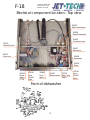
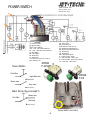
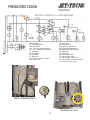
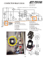
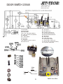
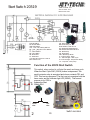
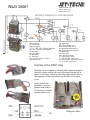
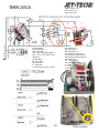
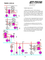
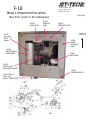
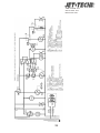
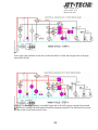
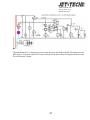
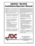
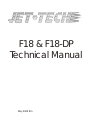
F18 & F18-DP
Technical Manual
May 2004 Rm
INDEX
PAGE 3 OVER VIEW OF TOP CONTROL PANEL
PAGE 4 DOOR SWITCH 20548
PAGE 5 POWER SWITCH 20044, 20500
PAGE 6 PRESSOSTAT 20058
PAGE 7 WATER LEVEL SYSTEM
PAGE 8 SOLENOID VALVE 20569
PAGE 9 THERMOSTAT, RINSE 20596
PAGE 10 THERMOSTAT, WASH 20570
PAGE 11 CONTACTOR RELAY 20104
PAGE 12 START SWITCH 20519
PAGE 13 START RELAY 20067
PAGE 14 TIMER 20518
PAGE 15 TIMER SEQUENCE
PAGE 16 ELECTRICAL DIAGRAM
PAGE 17 OVERVIEW OF THE BASE
PAGE 18 WASH SYSTEM/PLUMBING
PAGE 19 WASH SYSTEM (cont.)
PAGE 20 WASH PUMP 20240
PAGE 21 DRAIN PUMP 40229
PAGE 22 HEATER ELEMENTS 20080, 20088
PAGE 23 FILL CYCLE AND HEAT CYCLE
PAGE 24 HEAT CYCLE (cont.)
PAGE 25 WASH CYCLE
PAGE 26 WASH CYCLE (cont.)
PAGE 27 DRAIN CYCLE
PAGE 28-31
CHEMICAL PUMP ADJUSTMENT
PAGE 32 ELECTRICAL SCHEMATIC
2
1 888 275 4538 - 611
514 737 9701 - 611
FAX 514 737 2792
F-18
Electrical component location - Top view
20570
Wash thermostat
20596
Rinse Thermostat
20104
Contactor relay
20532
Terminal block
20067
Start relay
20567
Capacitor
20058
Pressostat
20518
Timer
20044
Power
switch
(F-18)
20010
Lens
20042
Light
20548
Door
switch
20519
20108
Thermometer Start cycle
switch
Front of dishwasher
3
20010
Lens
20042
Light
POWER SWITCH
1 888 275 4538 - 611
514 737 9701 - 611
FAX 514 737 2792
TL- Power Switch
PS- Pressure Switch
SW2- Drain Switch
CR1 + CR2 - Micro Relay Switches
M1 + M2 + M3: Timer Cam Switches
TC- Start Switch
MP - Door Switch
TB - Thermostat
TV - Thermostat
CCB - Booster Contactor Contacts
ELB - Solenoid Coil
PD - Soap Pump
BR - Micro Relay coil
BCB - Booster Contactor coil
RV - Wash Tank Heater Element
RB - Booster Tank Heater Element
DP - Drain Pump
MT - Timer Motor
MPL - Wash Pump Motor
LL - Indicator Light - Power
LC - Indicator Light - Wash Cycle
LP - Indicator Light - Temperature Ready
CA - Capacitor - wash pump
20500
F-18 DP
Power Button
Dark Blue
20044
F-18
Light Blue wire
Brown wire
Gray wire
Drain Pump By-pass switch
Brown wire
Pink Wire
Red wire
Power Switch Location
4
PRESSOSTAT 20058
1 888 275 4538 - 611
514 737 9701 - 611
FAX 514 737 2792
TL- Power Switch
PS- Pressure Switch
SW2- Drain Switch
CR1 + CR2 - Micro Relay Switches
M1 + M2 + M3: Timer Cam Switches
TC- Start Switch
MP - Door Switch
TB - Thermostat
TV - Thermostat
CCB - Booster Contactor Contacts
ELB - Solenoid Coil
PD - Soap Pump
BR - Micro Relay coil
BCB - Booster Contactor coil
RV - Wash Tank Heater Element
RB - Booster Tank Heater Element
DP - Drain Pump
MT - Timer Motor
MPL - Wash Pump Motor
LL - Indicator Light - Power
LC - Indicator Light - Wash Cycle
LP - Indicator Light - Temperature Ready
CA - Capacitor - wash pump
Back of dishwasher
Pressostat Location
5
Water Level System
1 888 275 4538 - 611
514 737 9701 - 611
The dishwasher water level is control by a pressure switch or
pressostat. A cup (grey plastic cylinder, #10528) located at the back of
the unit will keep an air pocket which will be pressurized as the water
level increases. The air pressure (approximately 2 inch water column)
activates a switch through a rubber tube that connects from the air trap
to the pressostat.
During the fill cycle, the water solenoid gets its signal from the
pressostat. When the pressostat is satisfied, it cuts the signal to the
solenoid valve and sends power to the thermostats and the timer
When trouble shooting this system, all components must be
considered.
Beginning with the pressostat which is adjustable.
Making sure the connection to the tube is air tight.
The tube may have an invisible crack which allows air to escape.
The air trap may be broken or the threads may have a crack also.
Adjustment (min-max)
Adjustment water level
Clock-wise for higher level
To heaters and timer
(white wire)
To water solenoid valve
(red wire)
from power switch
(grey wire)
6
Fill System & Rinse System
The dishwasher fill and rinse systems is practically the same system as they both used the same circuit.
The only difference is what is sending the signal to the water solenoid valve.
During the fill cycle, the water solenoid gets its signal from the pressostat. When the pressostat is
satisfied, it cuts the signal to the solenoid valve and sends power to the thermostats and the timer.
During the Rinse cycle, the water solenoid valve is getting its signal from the timer. When the time has
completed the rinse cycle than the solenoid is de-energized.
Because the detergent pump and the drain pump (if so equipped) are connected in parallel with the
water solenoid valve, they will all work at the same time. Why are they connected this way? Simple,
the detergent pump is connected this to inject detergent whenever new water comes into the
dishwasher. The detergent does not mix with the rinse system so it does not contaminate the rinsing
process with detergent.
The drain pump will
work whenever the
water solenoid
opens and this is to
avoid overflow
problem should the
pressostat becomes
defective and the
unit get stuck in a
fill cycle. Here it si
important to keep in
mind that this
scenario will only
work if the dynamic
(flow) water
pressure does not
exceed 25 PSI and the unit is capable of totally draining
within 1 minute. If any of those two factors exceeds the
limits then you can have an overflow situation.
The water solenoid valve will send water through the booster first and then water will travel to the
spray-arms as shown in the diagram below. The solenoid valve will fail under specific condition. High
pressure(>2.0 bar: >30 PSI) , high temperature(>60C:>140F), debris in water,
continuous work.
7
THERMOSTAT 20596
1 888 275 4538 - 611
514 737 9701 - 611
FAX 514 737 2792
Green paint
TL- Power Switch
PS- Pressure Switch
SW2- Drain Switch
CR1 + CR2 - Micro Relay Switches
M1 + M2 + M3: Timer Cam Switches
TC- Start Switch
MP - Door Switch
TB - Thermostat
TV - Thermostat
CCB - Booster Contactor Contacts
ELB - Solenoid Coil
PD - Soap Pump
BR - Micro Relay coil
BCB - Booster Contactor coil
RV - Wash Tank Heater Element
RB - Booster Tank Heater Element
DP - Drain Pump
MT - Timer Motor
MPL - Wash Pump Motor
LL - Indicator Light - Power
LC - Indicator Light - Wash Cycle
LP - Indicator Light - Temperature Ready
CA - Capacitor - wash pump
190F +/- 2
2
1
C
From pressostat (white)
3
1
2
G
8
Nc
3
No
To Wash thermostat
(blue)
To contactor
(red)
THERMOSTAT 20570
1 888 275 4538 - 611
514 737 9701 - 611
FAX 514 737 2792
Orange paint
TL- Power Switch
PS- Pressure Switch
SW2- Drain Switch
CR1 + CR2 - Micro Relay Switches
M1 + M2 + M3: Timer Cam Switches
TC- Start Switch
MP - Door Switch
TB - Thermostat
TV - Thermostat
CCB - Booster Contactor Contacts
ELB - Solenoid Coil
PD - Soap Pump
BR - Micro Relay coil
BCB - Booster Contactor coil
RV - Wash Tank Heater Element
RB - Booster Tank Heater Element
DP - Drain Pump
MT - Timer Motor
MPL - Wash Pump Motor
LL - Indicator Light - Power
LC - Indicator Light - Wash Cycle
LP - Indicator Light - Temperature Ready
CA - Capacitor - wash pump
160F +/- 2
2
1
C
Nc
3
No
From rinse thermostat (blue)
3
1
2
To ready light
(small black)
G
9
To wash heater element
(Large black)
CONTACTOR RELAY 20104
1 888 275 4538 - 611
514 737 9701 - 611
FAX 514 737 2792
TL- Power Switch
PS- Pressure Switch
SW2- Drain Switch
CR1 + CR2 - Micro Relay Switches
M1 + M2 + M3: Timer Cam Switches
TC- Start Switch
MP - Door Switch
TB - Thermostat
TV - Thermostat
CCB - Booster Contactor Contacts
ELB - Solenoid Coil
10
PD - Soap Pump
BR - Micro Relay coil
BCB - Booster Contactor coil
RV - Wash Tank Heater Element
RB - Booster Tank Heater Element
DP - Drain Pump
MT - Timer Motor
MPL - Wash Pump Motor
LL - Indicator Light - Power
LC - Indicator Light - Wash Cycle
LP - Indicator Light - Temperature Ready
CA - Capacitor - wash pump
DOOR SWITCH 20548
1 888 275 4538 - 611
514 737 9701 - 611
FAX 514 737 2792
TL- Power Switch
PS- Pressure Switch
SW2- Drain Switch
CR1 + CR2 - Micro Relay Switches
M1 + M2 + M3: Timer Cam Switches
TC- Start Switch
MP - Door Switch
TB - Thermostat
TV - Thermostat
CCB - Booster Contactor Contacts
ELB - Solenoid Coil
PD - Soap Pump
BR - Micro Relay coil
BCB - Booster Contactor coil
RV - Wash Tank Heater Element
RB - Booster Tank Heater Element
DP - Drain Pump
MT - Timer Motor
MPL - Wash Pump Motor
LL - Indicator Light - Power
LC - Indicator Light - Wash Cycle
LP - Indicator Light - Temperature Ready
CA - Capacitor - wash pump
White
wire
Door closed
White
wire
Door opened
11
Switch Location
Start Switch 20519
1 888 275 4538 - 611
514 737 9701 - 611
FAX 514 737 2792
TL- Power Switch
PS- Pressure Switch
SW2- Drain Switch
CR1 + CR2 - Micro Relay Switches
M1 + M2 + M3: Timer Cam Switches
TC- Start Switch
MP - Door Switch
TB - Thermostat
TV - Thermostat
CCB - Booster Contactor Contacts
ELB - Solenoid Coil
PD - Soap Pump
BR - Micro Relay coil
BCB - Booster Contactor coil
RV - Wash Tank Heater Element
RB - Booster Tank Heater Element
DP - Drain Pump
MT - Timer Motor
MPL - Wash Pump Motor
LL - Indicator Light - Power
LC - Indicator Light - Wash Cycle
LP - Indicator Light - Temperature Ready
CA - Capacitor - wash pump
Function of the 20519 Start Switch
1
This switch, when pushed in, will start the wash and rinse cycle.
When the Start Cycle SW1 (20519) button is depressed. The
small contactor relay is energized and closes contacts CR1 and
CR2. This has two purposes. The first one is to energize both the
timer motor and the indicator light LP3 (20042). The second
purpose is for CR2 to
bypass the Start
Switch SW1.
White
wire
2
Pink
wire
12
Switch Location
RELAY 20067
1 888 275 4538 - 611
514 737 9701 - 611
FAX 514 737 2792
TL- Power Switch
PS- Pressure Switch
SW2- Drain Switch
PD - Soap Pump
BR - Micro Relay coil
CR1 + CR2 - Micro Relay Switches
M1 + M2 + M3: Timer Cam Switches
TC- Start Switch
MP - Door Switch
TB - Thermostat
TV - Thermostat
CCB - Booster Contactor Contacts
ELB - Solenoid Coil
BCB - Booster Contactor coil
RV - Wash Tank Heater Element
RB - Booster Tank Heater Element
DP - Drain Pump
MT - Timer Motor
MPL - Wash Pump Motor
LL - Indicator Light - Power
LC - Indicator Light - Wash Cycle
LP - Indicator Light - Temperature Ready
CA - Capacitor - wash pump
Function of the 20067 relay
This relay once activated by the start-switch signal is design to
hold the current until the first cam of the timer hits the micro
switch on the timer. At that moment the signal on the relay is
disengaged and the timer takes over the start of the wash
cycle.
If this part fails, the
start switch must be
pressed and held for
15 seconds in order to
start the wash cycle.
13
Relay Location
TIMER 20518
1 888 275 4538 - 611
514 737 9701 - 611
FAX 514 737 2792
3
TL- Power Switch
PS- Pressure Switch
SW2- Drain Switch
CR1 + CR2 - Micro Relay Switches
M1 + M2 + M3: Timer Cam
Switches
TC- Start Switch
MP - Door Switch
TB - Thermostat
TV - Thermostat
CCB - Booster Contactor Contacts
14
2
1
ELB - Solenoid Coil
PD - Soap Pump
BR - Micro Relay coil
BCB - Booster Contactor coil
RV - Wash Tank Heater Element
RB - Booster Tank Heater Element
DP - Drain Pump
MT - Timer Motor
MPL - Wash Pump Motor
LL - Indicator Light - Power
LC - Indicator Light - Wash Cycle
LP - Indicator Light - Temperature Ready
Timer Location
TIMER 20518
1 888 275 4538 - 611
514 737 9701 - 611
FAX 514 737 2792
TIMER SEQUENCE
1
1- When the Start Cycle TC (20519) button is
depressed. The small contactor relay is energized and
closes contacts CR1 (20067) and CR2 (20067). This
has two purposes. The first one is to energize both the
timer motor and the indicator light LC (20042). The
second purpose is for CR2 to bypass the Start Switch
TC.
2- The timer motor is energized and starts to turn and
closes the first contact M1 (20518) which will bypass
the small relay contactor and keep the timer motor
running during the entire cycle.
3- As the timer cam continues to turn, the second
switch M2 (20518) is closed and energizes the wash
pump motor.
2
4- After 150 seconds approximately, switch M2 opens
and switch M3 (20518)closes to energize the solenoid
valve (for rinsing), the drain pump and the detergent
pump. This function lasts about 20 seconds and the
circuit reverts to the beginning.
3
4
15
F-18
1 888 275 4538 - 611
514 737 9701 - 611
FAX 514 737 2792
Base component location
May 2004
View from under of the dishwasher
40229
DRAIN PUMP
20199
RINSE-AID
PUMP
20588
DETERGENT PUMP
FRONT
60137
Drain Plug
60004
Gasket
20569
WATER
SOLENOID
VALVE
15689
BOOSTER TANK
RINSE WATER
40240
WASH PUMP
15019
BOTTOM HUB
WASH-ARM SUPPORT
20582
TERMINAL BLOCK
10349 (F18-DP)
10351 (F18)
DRAIN CONNECTION
16
1 888 275 4538 - 611
514 737 9701 - 611
FAX 514 737 2792
WASH SYSTEM
TL- Power Switch
PS- Pressure Switch
SW2- Drain Switch
CR1 + CR2 - Micro Relay Switches
M1 + M2 + M3: Timer Cam Switches
TC- Start Switch
MP - Door Switch
BR - Micro Relay coil
BCB - Booster Contactor coil
RV - Wash Tank Heater Element
RB - Booster Tank Heater Element
DP - Drain Pump
MT - Timer Motor
TB - Thermostat
LL - Indicator Light - Power
LC - Indicator Light - Wash Cycle
LP - Indicator Light - Temperature Ready
CA - Capacitor - wash pump
TV - Thermostat
CCB - Booster Contactor Contacts
ELB - Solenoid Coil
PD - Soap Pump
17
MPL - Wash Pump Motor
1 888 275 4538 - 611
514 737 9701 - 611
FAX 514 737 2792
WASH SYSTEM
Rinse
Wash
18
1 888 275 4538 - 611
514 737 9701 - 611
FAX 514 737 2792
WASH SYSTEM
WASH PUMP
. . . 40240
9A-9BMECHANICAL SEAL
7A-7BPUMP BOTTOM HOUSING
11 PUMP HOUSING
10 IMPELLER
12 GASKET
. . . . 40030
. . . . 40218
. . . . 40083
. . . . 40269
. . . . 40113
19
DRAIN PUMP 40229
1 888 275 4538 - 611
514 737 9701 - 611
FAX 514 737 2792
TL- Power Switch
PS- Pressure Switch
SW2- Drain Switch
CR1 + CR2 - Micro Relay Switches
M1 + M2 + M3: Timer Cam Switches
TC- Start Switch
MP - Door Switch
TB - Thermostat
TV - Thermostat
CCB - Booster Contactor Contacts
ELB - Solenoid Coil
PD - Soap Pump
40115
BR - Micro Relay coil
BCB - Booster Contactor coil
RV - Wash Tank Heater Element
RB - Booster Tank Heater Element
DP - Drain Pump
MT - Timer Motor
MPL - Wash Pump Motor
LL - Indicator Light - Power
LC - Indicator Light - Wash Cycle
LP - Indicator Light - Temperature Ready
CA - Capacitor - wash pump
40127
40129
Drain opening in wash tank
40128
20
Drain Pump Location
1 888 275 4538 - 611
514 737 9701 - 611
FAX 514 737 2792
F18 Booster
Do not
connect
Do not
connect
TL- Power Switch
PS- Pressure Switch
SW2- Drain Switch
CR1 + CR2 - Micro Relay Switches
M1 + M2 + M3: Timer Cam Switches
TC- Start Switch
MP - Door Switch
TB - Thermostat
TV - Thermostat
CCB - Booster Contactor Contacts
ELB - Solenoid Coil
PD - Soap Pump
BR - Micro Relay coil
BCB - Booster Contactor coil
RV - Wash Tank Heater Element
RB - Booster Tank Heater Element
DP - Drain Pump
MT - Timer Motor
MPL - Wash Pump Motor
LL - Indicator Light - Power
LC - Indicator Light - Wash Cycle
LP - Indicator Light - Temperature Ready
CA - Capacitor - wash pump
21
1 888 275 4538 - 611
514 737 9701 - 611
FAX 514 737 2792
22
1 888 275 4538 - 611
514 737 9701 - 611
FAX 514 737 2792
ELECTRICAL SEQUENCE
As the unit is powered by the Power Switch (1), it energizes LL(2).
The Pressure-switch PS energies the solenoid valve ELB (to fill the wash tank), the detergent pump
PD and the drain pump DP.
When the pressure-switch PS(20058) is satisfied, it energizes the Booster relay contactor
BCB(20104) by the rinse thermostat TB(20596).
23
1 888 275 4538 - 611
514 737 9701 - 611
FAX 514 737 2792
When the Booster thermostat TB is satisfied, it energizes the wash tank heater element RV by the
wash thermostat TV.
When the thermostat in the wash tank is satisfied, it energizes the indicator light LP.
24
1 888 275 4538 - 611
514 737 9701 - 611
FAX 514 737 2792
When the Start Cycle TC (6-20519) button is depressed. The small contactor relay (20067) is
energized and closes contacts CR1 and CR2. This has two purposes. The first one is to energize both
the timer motor and the indicator light LC (7). The second purpose is for CR2 to bypass the Start
Switch TC.
The timer motor MT is energized and starts to turn and closes the first contact M1 which will bypass
the small relay contactor and keep the timer motor running during the entire cycle.
25
1 888 275 4538 - 611
514 737 9701 - 611
FAX 514 737 2792
As the timer cam continues to turn, the second switch M2 is closed and energizes the wash pump
motor MPL(40240).
After 150 seconds approximately, switch M2 opens and switch M3 closes to energize the solenoid
valve ELB (for rinsing), the drain pump DP and the detergent pump PD. This last about 20 seconds
and the circuit reverts back to timer at rest..
26
1 888 275 4538 - 611
514 737 9701 - 611
FAX 514 737 2792
The drain button Sw2 is depressed, power is sent directly to the drain pump DP. The button most be
held in place. If the power switch TL is not switched off, the unit will try to fill again when the water
level reach about 2 inches.
27
1 888 275 4538 - 611
514 737 9701 - 611
FAX 514 737 2792
CHEMICALS AND PUMP ADJUSTMENT
Dishwashers require the use of a detergent and possibly a rinse additive. The detergent
must be of commercial strength to work in the unit’s short cycle. The rinse additive will
help the water to sheet on the glasses and plates, acting as a drying agent.
The products are a Sodium Hydroxide for the detergent and a surfactant isopropanol for
the rinse. Quantities will vary with water quality but as a guideline there should be 200
ppm for the detergent and 50 ppm for the rinse-agent. Those products are available from
any chemical company. Never use chlorinated product such as sanitizer and bleach.
These products can damage the equipment.
Should you run out of these products, you can use residential brand product as a
temporary measure. Do NOT use soap that produces suds. Use those product that are
sold for dishwashers. Good quality chemical product will improve the washing.
Models 727, 737, F-16, F-16DP, F-18, F-18DP & F-20 are supplied with a factory installed
liquid detergent pump to automatically dispense detergent into the wash tank chambers.
Before accessing the bottom section of the dishwasher, make sure that the power was
turned off at the source (breaker panel).
The bottom panel can only be remove with a flat tool
like a screw-driver. Insert the screw-driver in the gap
between the front panel and the side panel. Pry open
towards you. Do this on both side.
The clear hoses connected to the pumps must be
pulled out and fed through the bottom of the
dishwasher. The containers can be either to the right
or left of the dishwasher. Perforating the stainless
panel is not recommended.
28
1 888 275 4538 - 611
514 737 9701 - 611
FAX 514 737 2792
The quantity of liquid detergent can be increased
(clockwise) or decreased (counter clockwise) by adjusting
the screw on the peristaltic pump. The pump works during
the fill cycle and rinse cycle.
(Identified above as “Adjustment screw”)
Don't forget to put the panel back on when finished.
RINSE PUMP ADJUSTMENT AND PRIMING
· The rinse pump is standard equipment on all JET-TECH machines and automatically injects
rinse additive into the rinse water for the final rinse.
· The rinse pump is located
in the base of the machine
near the booster tank. The
front, lower panel (below the
door) snaps off to access the
rinse pump. Cut the cable
tie, route the tube out from
the base of the machine and
drop the clear vinyl hose and
filter into your rinse additive
container. (Some models are
supplied with a rinse additive
bottle that fits inside the
base of the machine)
Adjustments should be made clockwise to reduce the amount of rinse additive and counter
clockwise to increase the amount of rinse additive.
· If air gets in the rinse hose or if the pump stops drawing additive from the container, the pump
may need to be primed.
To Prime (accelerate the injection of chemical) the pump, follow these steps;
1) Turn OFF the machine, pull the overflow, and drain
the wash tank. The wash tank must be empty has
priming is done during the fill cycle.
2) Get access to rinse-additive pump (see above
instructions) Turn the adjusting screw on the rinse
pump approximately 10 turns counter clockwise,
allowing maximum travel for the piston. The screw
may fall out but this is not a problem. Just remember
how many turns you had made when the screw fell
out.
3) Turn the machine ON and count to 5, then turn the
machine OFF and count to 5, do this several times,
until the liquid is drawn up the tube to the rinse pump.
Because the pump works when the water solenoid
29
1 888 275 4538 - 611
514 737 9701 - 611
FAX 514 737 2792
opens, causing the water pressure to push the internal piston, you should be able to see the
liquid travel the length of the tube.
4) Once the liquid as reached the back of the pump, turn the adjusting screw on the rinse
pump clockwise all the way in and counter-clockwise 3 full turns.
The rinse-aid pump can pump up to 3cc of rinse-additive (drying agent). The liquid is injected
directly in to the booster tank.
DO NOT use sanitizer (chlorinated products, bleach) with this pump. It is not made to pump
harsh chlorinated liquid. This will void warranty on the dishwasher.
Know Your Application.
When purchasing the detergent, it is important to specify what you want to wash. Most
detergents sold on the market are good for regular soil (Non-greasy food on dishes and
cups). Coffee and lipstick stains are usually very difficult to remove and pre-washing may be
required. Greasy pans will involve a more specialize product. If an incorrect product is used,
grease will accumulate inside the washing cabinet and cover everything.
For any other request on set-up and installation, please contact us at 1 888 275 4538
extension 611...
IMPORTANT
Remember to always use caution and protective gears whenever you are manipulating
chemicals. They can burn the skin. Follow supplier’s instructions carefully.
SPECIFICATIONS
Peristaltic pumps for dish-washing machines
Electronic regulation time-pause
G82
- max. delivery 0,6 l/h - silicone tube for rinse additive
- max. delivery 0,8 l/h - thermoplastic tube for detergent
G152
- max. delivery 1,5 l/h - thermoplastic tube for detergent
G202
- max. delivery 2,0 l/h - thermoplastic tube for detergent
G252
- max. delivery 2,3 l/h - thermoplastic tube for detergent
230V 50/60Hz (24V by request)
* On request: Silicone tube
1 litre = 35.195 once
.55 ml/sec
30
1 888 275 4538 - 611
514 737 9701 - 611
FAX 514 737 2792
Components
20588
20352
40147
20199
31
1 888 275 4538 - 611
514 737 9701 - 611
FAX 514 737 2792
32