1
Indoor | Outdoor
45246
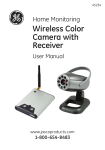
Home Monitoring
Wireless
Color Camera
and Receiver
User Manual
www.jascoproducts.com
1-800-654-8483
Table of Contents
Product Features..................................................................... 3
Package Contents................................................................... 4
Before you Install..................................................................... 4
Choosing A Camera Mounting Location...................... 5
Receiver Channel Selection................................................ 7
Manual Mode............................................................................ 7
Auto Mode (two camera operation)............................... 8
Cycle Time Setting (Time Interval between
camera selections)........................................................... 9
Camera Channel Selection................................................. 9
Connecting to a TV or Monitor........................................11
Using the Wireless Color Camera System
with a VCR or DVR...........................................................13
Long Range Night Vision...................................................13
Auto Detection and Notification Feature..................14
Camera Installation.............................................................14
Troubleshooting.....................................................................19
Specifications..........................................................................21
Warranty...................................................................................22
FCC Statement........................................................................23
3
Thank you for purchasing the GE 45246 Wireless
Color Camera System with Receiver. Please review
these instructions carefully before attempting to
operate the unit.
PRODUCT FEATURES
• Weather resistant metal camera casing,
designed for outdoor use
• Black anodized finish prevents rust and
unwanted reflections
• Long Range Night Vision — high-powered LED’s
allow you to see up to 60ft. in the dark
• Vandal resistant bracket hides cable
• Adjustable sun shield to minimize glare
• “Wi-Fi” internet friendly wireless system—
won’t interfere with home wireless networks.
• Wirelessly transmits audio and video up to
200 ft. (unobstructed line of sight).
• View up to two cameras
• Audio Detection & Notification feature—alerts
when sound is detected in a monitored area
• Multi-axis camera mount allows for installation
at any angle
• Receiver connects to any TV or monitor with
AV inputs
4
PACKAGE CONTENTS
Please check and identify all the parts before
proceeding with the installation.
1. Wireless camera and receiver
2. Mounting hardware for camera (3 screws,
3 plastic anchors)
3. 2 AC adapters
4. AV cable
5. Adjustment wrench
BEFORE YOU INSTALL
When choosing the best location for the placement
of the camera and receiver, it is best to avoid any
sources of possible RF interference such as
microwave ovens and cordless phones. Proximity
to these and other sources of RF interference can
inhibit the proper functioning of the receiver.
The 900MHz video signals pass easily through
your home’s interior walls, but the signal may be
reflected by power wires or plumbing inside those
walls. Usually a slight adjustment to the position
of the Receiver and/or Camera antenna will
improve reception. Position the antenna upwards
or downwards (depending on mounting location)
to improve sensitivity. Take care not to force the
antenna past its lock positions.
5
CHOOSING A CAMERA MOUNTING LOCATION
The Wireless Color Camera is suitable for indoor or
outdoor use. When choosing a mounting location,
please be advised:
• This camera is designed to be reliable for
outdoor use; and its flexible design allows it to be
used indoors as well.
• If using outdoors, take time to first consider
how you will route the cable back to the power
adapter. The AC adapter must be used in
a dry location. The cable is routed through
the mounting bracket so it can run hidden
through walls. This provides a vandal-resistant
design. There is also a slot located at the base
of the mounting plate so the cable can exit
the mounting bracket and run on the outdoor
surface, if desired.
• The universal multi-axis bracket allows you to
mount the camera at almost any angle.
• DO NOT position the camera so that it points
directly into the sun or any bright light, as this
may cause damage to the camera.
6
• Avoid positioning the camera so that it is viewing
areas where half of the area is in bright sunlight
and the other half is dark, such as the shadow
of a building. All types of cameras have difficulty
“seeing” into areas of such divergent light levels.
• In low light conditions, the camera will
automatically activate its high-powered Infrared
(IR) LED’s and switch the camera to Long Range
Night Vision mode. Long Range Night Vision
viewing distance can be up to 60ft, and will be
viewed in B/W.
• The included AC adapters must be positioned
no farther than 8’ from an AC outlet. Do not use
either supplied adapter outside. If you need to
extend an AC adapter cable, 12 ft. extensions
are available by contacting Technical Support at
800-654-8483.
• The Camera has an unobstructed wireless
transmission range up to 200 ft. from the
receiver. Transmission distance indoors is
reduced due to interior walls, wiring, household
fixtures and metal plumbing.
7
RECEIVER CHANNEL SELECTION
The receiver system can monitor up to 2 wireless
cameras. You can operate the receiver in either
Manual or Auto mode. To view more than one
camera, locate the camera channel selection
switch (1 2 1/2) on the rear panel of the
receiver.
The receiver must be set to the ‘1/2’ position to
allow two cameras to be monitored. The next step
will be to set the channel selection switch on both
cameras. See Camera Channel Selection.
MANUAL MODE
Auto
Manual
Operating the receiver in
manual mode allows you
to manually select a single
camera/channel to monitor
exclusively. The system will Channel
Selection
remain on the selected
switch
channel indefinitely until the
other channel is selected. To select one of the two
channels (cameras) manually, locate the AUTO
and MANUAL buttons on the top of the receiver.
Press and release the MANUAL button. The red LED
labeled ‘A — M’ will turn on and the corresponding
8
channel (1 or 2) LED will turn on. The receiver
will switch to a different channel each time the
MANUAL button is pressed. The video image for
the channel with an active camera selected will
appear on the monitor. Each camera must be
assigned to a specific channel; both cameras
cannot be on the same channel or the signals will
interfere with each other.
AUTO MODE (two camera operation)
To have the receiver automatically switch between
two active channels, first check the receiver is set to
1/2 position. Next, press the AUTO button on the top
panel of the receiver. The green LED will light and
the receiver will automatically select between the
two active cameras. The monitor will display images
from both cameras alternately.
2
1
CAMERA 1
Channel Setting
1 2
2
1
CAMERA 2
Channel Setting
1 2
1 2 1/2
RECEIVER
Channel Setting
9
CYCLE TIME SETTING (Time interval between
camera selections)
The default cycle time for the receiver to switch
between cameras in auto mode is preset to 4
seconds. To change the cycle time, press and hold
both of the buttons (Auto and Manual) on top of
the receiver simultaneously. The receiver will beep,
pause and then sound a beep for each second of
the cycle time, up to 30 seconds. The total cycle
time can be verified by the number of LED flashes/
beeps made when you release the buttons—one
flash/beep equals one second. Cycle time can be
set between 4-30 seconds. If the power adapter is
removed or the receiver loses power, the cycle
time defaults back to 4 seconds.
CAMERA CHANNEL SELECTION
This wireless surveillance system is designed to
monitor up to two cameras. Additional cameras are
sold separately.
IMPORTANT: When using more than one camera,
each camera must be assigned to a specific
channel using the channel selection switch
located on the inside the front of the camera
housing.
10
Channel Selection Switch
2
1
The camera will be set to channel 1 from the
factory. To change the camera to channel 2, you
will need to remove the sun shield and unscrew
the lens cover. Locate the channel selector. Slide
the switch to channel 2 and screw on the lens
cover back on until it’s snug. Each camera must
be assigned to a specific channel; both cameras
cannot be on the same channel or the signals will
cancel out. If using only one camera you can select
either Ch 1 or Ch 2, whichever provides the best
picture. The slide switch located on the rear of the
Receiver must be set to reflect the channels in use.
Set the receiver to Ch 1, Ch 2, or Ch 1/2. See further
instructions in the receiver section (page 7).
11
CONNECTING TO A TV OR MONITOR
To prepare for installation of the system, we
recommend that you temporarily connect the
Wireless Receiver to a TV or Monitor to help you
choose the best location for installing the camera.
The camera connects wirelessly and automatically
to the receiver when both are powered on and are
located within 200 ft (unobstructed view) of each
other. This system will accommodate up to two
cameras.
NOTE: There are two AC adapters. One is labeled
‘Receiver’ at the end of the cable. The other is
labeled ‘Camera’ at the end of the cable. It is
important to use the appropriate AC adapter for
each product. Using the wrong adapter could
permanently damage the camera or receiver.
TV
Video In
Audio In
Yellow
White
12
1. Plug the AC adapter for the Wireless Receiver
(labeled ‘Receiver’) into the power jack (marked
‘DC 9V’ on the back of the receiver), then into an
AC outlet. Select the desired channel on the back
of the receiver (see Receiver Channel Selection).
2. After selecting the channel for the camera (see
Channel Selection). Plug the AC adapter for the
camera (labeled ‘Camera’) into cable coming from
the camera. Plug the AC adapter into an AC outlet.
3. Locate the AV cable. It has a 3.5mm male plug
at one end, and two RCA plugs at the other end.
Connect the 3.5mm male to the rear jack of the
receiver, marked ‘A/V Out’. Connect the other
ends (white/yellow) to your television’s A/V inputs.
Match the yellow plug to the yellow VIDEO IN jack
and the white plug to the white AUDIO IN jack.
4. Rotate the antenna, on the receiver, to a vertical
position. Place the receiver either on top of or
near to your TV monitor.
5. Set your TV to monitor the VIDEO INPUT
designated for the Receiver.
6. Place camera near desired location and check
quality of transmitted image on the monitor.
13
USING THE WIRELESS COLOR CAMERA SYSTEM
WITH A VCR or DVR
You can connect the receiver to a VCR or DVR in
order to record the images received from up to two
cameras. The VCR or DVR must also be connected to
a TV/Monitor in order to see live or recorded images.
See diagram below.
TV
Video
In
Audio
In
VCR
Video
In
LONG RANGE NIGHT VISION
The Wireless Color Camera
features Long Range Night
Vision technology. Objects
and images can be seen in
little or no light up to 60 ft.
The camera uses a special
image sensor that
automatically detects
available light levels.
Audio
In
Audio Video
Out Out
20 Infrared
(IR) LEDs
Sensor
Sensitivity
Control Wheel
14
It turns on/off the high-powered Infrared (IR) LEDs
on the front of the camera. These LEDs provide
artificial light that allows the camera to see in the
dark. Long Range Night Vision will appear as a
Black and White image. When the image sensor
detects enough light, color will return to the images.
AUDIO DETECTION AND NOTIFICATION FEATURE
This feature allows the Receiver to emit an audio
alert whenever sound is detected within a
monitored area. To activate the detection feature
press and release the button located on the front
of the receiver. When the camera detects a sound,
the receiver will sound an alert and a notification
light will flash. The sensitivity for the level of audio
detection (when the receiver will sound an alert)
can be adjusted with the sensitivity control located
at the back of the receiver. Set the sensitivity to
the highest level and press the button on the front.
Adjust the sensitivity control to desired level.
CAMERA INSTALLATION
Wall Mount or Ceiling Mount — you will need:
- Drill
- 3/8" Drill bit (if running power cable thru wall
or ceiling)
- 1/8" drill bit (for drilling screw pilot holes if mounting,
into wood or non-brick material)
15
- 3/16" drill bit (for drilling holes, if using plastic
anchors to mount onto drywall or brick material)
- Screwdriver
- Adjustment wrench (included)
Step 1. Mounting preparation
Once a suitable location for the
camera has been selected and
the cable route has been
determined, you will need to use
the camera’s mounting bracket
as a template to mark holes for
drilling. Mark three holes on the
wall for the anchors or screws as shown. Please take
care to mark the center of the holes.
Note: Before mounting camera permanently,
check to ensure the appropriate channel has been
selected (see Channel Selection) to provide good
reception at the receiver/monitor.
Step 2. Cable routing -IMPORTANT
(a) If running the cable along the wall surface,
position cable through slot at base of mounting
bracket before installing mounting bracket (see
figure A).
16
Figure A (Running cable on surface of wall)
Pilot holes for
mounting screws
(b) If the cable needs to be ran through a wall or
ceiling, then an additional hole will need to be
drilled using the 3/8” drill bit. Drill the hole in the
center of the three mounting screw holes (see
figure B). Fit connector and cable through hole
before securing the mounting bracket.
Figure B
Plastic anchors
17
Step 3. Mounting bracket
(a) If mounting to a stud, wood surface or other
non-brick material, use the 1/8” drill bit to drill pilot
holes; drill holes. Align holes in mounting bracket
to drilled holes, insert screws and screw in until
plate has secure fit. Do not over tighten screws.
(b) If mounting to drywall or brick material, use
plastic anchors (see Figure C). Using 3/16” drill bit
(masonry bit, if drilling into brick), drill holes and
insert anchors into drilled holes for snug fit. Align
holes in mounting bracket to drilled holes, insert
screws and screw in until plate has secure fit. Do
not over tighten screws.
Figure C (Mounting bracket using plastic anchors)
Plastic anchors
(c) Using included adjustment wrench, slightly loosen
the hex head bracket nuts on camera bracket to
position camera’s multi-axis bracket so camera
is pointed toward desired viewing area. Tighten
bracket nuts. Do not over tighten nuts.
18
Proper
(d) Take care to position the
Position
camera in the correct
Channel
orientation. To ensure
Selection
the camera image is not
Lens
positioned upside down,
Light
you may have to rotate
Sensor
the camera housing so
the channel slelection
switch is positioned above the lens and the light
sensor is below the lens.
1
2
Step 4. Antenna Adjustment
Once mounted adjust
the camera’s antenna to
achieve best reception.
Note if ceiling mounted,
you may not be able to
position the antenna
completely vertical (pointed
up). It is acceptable to
position the antenna
vertically but pointed down.
This typically will not cause
any interference or reduce
the reception ability of the
camera. Do not force the
antenna beyond physical
stops.
Antenna
Rotation
Wall
Mount
Ceiling
Mount
19
Step 5. AC Power
Locate the power cable end connection. Attach the
AC adapter (labeled ‘camera’) to end of cable coming
from the camera. Plug-in AC adapter to nearest AC
outlet. Adapter must be used in a dry location. AC
power extension cables are available from the Call
Center 1-800-654-8483 or visit online at
www. jascoproducts.com
TROUBLE SHOOTING
If you are having trouble operating this product,
please consult the guide below. If you have any
questions or feel the camera system is not
operating correctly, or you simply need additional
information, please visit our web site
www.jascoproducts.com, or contact our Technical
Support Group 1-800-654-8483.
No camera picture
1. Check all connections. Make sure camera(s) and
receiver power LEDs are ON.
2. Ensure camera(s) and receiver are set to correct
and corresponding channel(s).
3. Make sure camera is within range of receiver (up
to 200 ft.).
4. Adjust the antenna for the camera, receiver or
both to obtain best image.
20
Blank monitor
1.Make sure receiver or monitor is switched ON.
Ensure the correct video input on the TV/monitor
has been selected.
2. Make sure video cable is connected to TV/monitor.
Interference on camera picture
1. Make sure each camera (transmitter) is within
range, and that no large obstructions are blocking
the signal.
2. Try repositioning the camera, receiver or both
to different locations in order to improve the
reception quality.
3. If using two cameras, make sure the cameras are
not set to the same channel.
4. Reposition other nearby equipment transmitting
on the 900MHz frequency.
5. Adjust the antenna for the camera, receiver or
both to obtain best image.
The image is upside down
You may have to rotate the camera housing. Loosen
the hex head nut and rotate housing so that the
channel selection switch is above the lens (see
page 17).
Audio problems
1. Ensure the volume is turned up sufficiently on the
Monitor (or TV).
21
2. Make sure the sound is within the microphone
range.
3. If the unit emits a loud wailing sound (feed back),
try moving the camera away from the receiver or
angle the receiver differently.
4. Make sure the audio cable is connected to the TV/
monitor.
SPECIFICATIONS
(Subject to change without notice.)
CAMERA
TV System......................................................................................................NTSC
Integrated Lens................................................... 6.0mm, F1.5 fixed focus
Resolution............................................................................ 510x496 TV Lines
Image Sensor................................................................................... 1/3” CMOS
Min. Illumination................................................................ 0.5lux up to 60 ft
Voltage............................................................................................................9VDC
Current Consumption...................................................330mA maximum
Overall Size.................................................................... 2.5”W x2.25Hx6.75D
Frequency Range....................................................................902 - 928 MHz
Modulation.........................................................................................................FM
Channel Selection................................................................................Manual
Case Finish......................................................................................... Aluminum
Operating Temperature.........................14°F to 104°F (-20°C to 55°C)
Humidity.....................................................................................Less than 85%
RECEIVER
Voltage............................................................................................................9VDC
Current Consumption..................................................100 mA maximum
Frequency Range....................................................................902 - 928 MHz
Output..............................................................................................Audio/Video
Overall Size........................3.8” L x 2.8” W x 0.6” H (Without antenna)
22
ONE-YEAR LIMITED WARRANTY
Jasco Products Company warrants this product to
be free from manufacturing defects for a period
of one year from the original date of consumer
purchase. This warranty is limited to the repair or
replacement of this product only and does not
extend to consequential or incidental damage to
other products that may be used with this unit. This
warranty is in lieu of all other warranties express
or implied. Some states do not allow limitations on
how long an implied warranty lasts or permit the
exclusion or limitation of incidental or consequential
damages, so the above limitations may not apply to
you. This warranty gives you specific rights, and you
may also have other rights which vary from state
to state. If unit should prove defective within the
warranty period, return prepaid with dated proof of
purchase to:
Jasco Products Company
10 E. Memorial Road,
Oklahoma City, OK 73114
23
FCC STATEMENT
WARNING
This device complies with part 15 of
Risk of fire and shock
the FCC rules. Operation is subject
• Only use the supplied cUL listed AC to DC adapter.
to the following two conditions:
• The supplied adapter is for indoor use only.
• When securing the cable, do not cut or puncture
(1) This device may not cause
• Do not use in wet locations
harmful interference.
(2) This device must accept any
interference received, including
interference that may cause undesired operation.
FCC NOTE: The manufacturer is not responsible
for any radio or TV interference
ADVERTENCIA
caused by unauthorized modifications toRIESGO
this equipment.
DE INCENDIOSuch modifications
• Utilice
el adaptador de CA a CC aceptado por UL.
could void the user’s authority to operate
the solamente
equipment.
• El adaptador que se incluye debe usarse solamente en
NOTE: This equipment has been tested and
found to comply with the limits
espacios interiores.
Al asegurar
permita
que seThese
corte o selimits
perfore.
for a Class B digital device, pursuant to •Part
15 ofel cable,
the no
FCC
Rules.
• Para uso en lugares secos solamente.
are designed to provide reasonable protection
against harmful interference
in a residential installation. This equipment generates, uses and can radiate
radio frequency energy and, if not installed and used in accordance with the
instructions, may cause harmful interference to radio communications. However,
there is no guarantee that interference will not occur in a particular installation.
If this equipment does cause harmful interference to radio or television reception,
which can be determined by turning the equipment off and on, the user is
encouraged to try to correct the interference by one or more of the following
measures:
- Reorient or relocate the receiving antenna.
- Increase the separation between the equipment and receiver.
- Connect the equipment into an outlet on a circuit different from that to which
the receiver is connected.
- Consult the dealer or an experienced radio/TV technician for help.
is a trademark of General Electric Company
and is used under license to Jasco Products Company LLC,
10 E. Memorial Road, Oklahoma City, OK 73114
www.jascoproducts.com
45246 rev. 5-18-10