1
Dishmachine Component
Maintenance Instructions
Parker-Style
Solenoid Valve
Repair Kits
07610-003-05-39 A
April 15, 2005
www.jacksonmsc.com
Many Jackson dishmachines are equipped with electrical
solenoid valves to allow for automatic fill and rinse. These valves
are designed to specific tolerances and design aspects that must
be met in order to function properly.
Jackson offers repair kits for replacing some of the wear
items associated with solenoid valves which will allow you to save
money in that replacement of these parts can take place without
removing the solenoid valve from the plumbing assembly.
The instructions provided here are for maintenance personnel only. Unauthorized persons should not attempt any of the
steps contained in these instructions.
STEPS
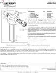
1. Remove the top screw with the 5/16” nutdriver. Remove the
screw and the data plate and set to the side.
Warning: many of the instructions and steps within
this document require the use of tools. Only authorized personnel should ever perform any maintenance procedure on
the dishmachine!
PREPARATION
1. Power must be secured to the unit at the service breaker. Tag or lock out the service breaker to prevent accidental or
unauthorized energizing of the machine.
2. Ensure that incoming water to the machine is secured
either by use of a shut-off valve or disconnecting the incoming
water line.
TOOLS REQUIRED
The following tools will be needed to perform this maintenance evolution:
1. Small flathead screwdriver
2. Medium flathead screwdriver
2. Needle nose pliers
3. 5/16” nutdriver
4. Channel locks
5. 12” pipe wrench
Removing the top screw
2. With the top screw and data plate removed, grasp the solenoid
coil and gently pull up. The coil should slide up, allowing you to
remove it from the valve bonnet. If you are wanting to replace the
coil, continue on with Step 3. If you are wanting to replace some of
the internal components of the valve, proceed to step 12.
TIME REQUIRED
It is estimated that it will take (1) person twenty minutes to
perform this task, not including all of the items indicated in the section entitled “PREPARATION”.
IMPORTANT NOTES
Removing the coil
1. Read these instructions thoroughly before attempting
this maintenance evolution. Become familiar with the parts and
what actions need to be taken. This will save time in the long run!
2. The procedures demonstrated in this manual are
shown being performed on an AJ-44 rack conveyor dishmachine.
The actual maintenance steps, however, apply to any Parker style
solenoid valve found on a Jackson dishmachine.
3. NOTE: Replacing the solenoid coil requires working with the
wiring of your machine. It is important that all wiring maintenance
be performed by qualified personnel. Always verify the wiring steps
presented in this instruction with the schematic that shipped with
the unit. A current schematic can also be found in the unit’s installation manual. Before beginning any step that involves working
with wiring, ensure that the steps located in the section entitled
“Preparation” have been performed. Power must be secured to the
machine at the service breaker. Failure to do so could result in
severe injury to maintenance personnel.
2
Parker Style Solenoid Valve Repair Kit Instructions
Revision A (04/15/2005)
www.jacksonmsc.com
Prying open the coil wire cover
4. When replacing the coil, ensure that when removing the coil wire
cover that care is taken not to damage the wires inside. Using the
medium flathead screwdriver, gently use it to open the cover
enough to where it could be pulled off.
Loosening the conduit nut
7. Using a pair of channel locks, gently loosen the conduit retaining ring for the conduit nut. Once it is loosened, use your fingers to
unscrew and remove it.
8. Pull the conduit away and discard the bad coil. Take the new coil
and attach the conduit, reinstall & tighten the conduit nut, and pullg
the wires through so that you will be able to wire the valve back up.
9. Reconnect the wires from the conduit to the wires from the solenoid as they had been connected previously. Ensure that the wire
nuts are on tight.
10. Slide the coil wire cover back on, taking care not to damage the
wires.
11. If you are done performing maintenance on the valve, continue
on to step 23. Otherwise, please go on to step 12.
Straightening the wires
5. Once the coil wire cover has been removed and set to the side,
take the internal wires and pull them out straight.
Loosening the valve bonnet
Removing the wire nuts
6. Remove the wire nuts from the wires and separate them.
Parker Style Solenoid Valve Repair Kit Instructions
Revision A (04/15/2005)
12. To remove the valve bonnet, grasp it with the jaws of the pipe
wrench and turn to the left. Note: on some models you may have
3
www.jacksonmsc.com
to remove the valve in order to perform this and any further steps.
Be careful not to damage the plumbing assembly. Only use the
pipe wrench enough to where you can spin the valve bonnet off
with your hand.
Removing the diaphragm
Removing the valve bonnet
13. Slowly remove the valve bonnet. Note: The spring for the
plunger is located directly under the bonnet and may come free if
you are not careful. Remove the plunger, spring and valve bonnet
and place to the side.
17. Remove the diaphragm retainer and then the diaphragm itself.
Many problems associated with a solenoid valve can be traced to
a clogged pilot port in the diaphragm.
Pointing out the extension hole
Removing the O-ring
14. Remove the O-ring and inspect it. If it has any tears or cuts or
excessive flat spaces, it should be replaced.
18. As indicated in the photo above, the extension hole can
become clogged. If it is difficult to clean out, you can use a heated
straight pin to push through the hole. The center hole, the pilot port,
must also be clear. If the diaphragm is torn or bent in any way, it
must be replaced.
15. Examine the threads for the valve bonnet. Check them for scoring or signs of damage. Take a cloth and clean them out to remove
any foreign particles that might get lodged in the threads and cause
a leak. Severely damage threads should not be repaired; instead it
is recommended that the entire valve should be replaced. These
instructions do not provide information on replacing the solenoid
valve.
1
2
16. Note: Even though an O-ring may not appear damaged, it is a
good idea to go ahead and replace it if you have a new one. This
will help ensure that your valve remains leak-free in the future!
Diaphragm showing (1) pilot port and (2) extension hole
4
Parker Style Solenoid Valve Repair Kit Instructions
Revision A (04/15/2005)
www.jacksonmsc.com
22. With the mesh screen removed, look down into the valve and
verify it is not clogged. Remove any foreign objects from the valve
body that would obstruct flow.
23. Reassemble the valve, reversing the steps needed to take it
apart. Replace defective replacement parts with new parts from
ordered kits. Ensure that components are sufficiently tightened to
prevent leakage.
AFTER MAINTENANCE ACTIONS
Reconnect the incoming water (if disconnected) and turn
on. Then restore power to the unit. Run the unit for at least 10 minutes to ensure there are no leaks. If any problems arise you can
contact Jackson Technical Service.
Removing the screen retainer
SPECIAL NOTES
20. Using the small flathead screwdriver, lift out the screen retainer. Verify that the holes in it are free of clogs and debris.
Work performed on Jackson dishmachines by unauthorized or unqualified personnel may void the warranty. Before beginning this or any other maintenance evolution on a unit under warranty, you should contact a certified Jackson technician or Jackson
Technical Service. You can find a list of qualified service agencies
in the back of you unit’s installation manual.
SPECIAL PARTS
Solenoid Valve Plunger Kit
Includes plunger and spring
Part number 04810-200-09-18
Solenoid Valve Diaphragm Kit
Includes diaphragm and o-ring
Part number 04810-200-03-18 (1/2” NPT)
Part number 04810-100-10-18 (3/4” NPT)
Solenoid Valve 110 Volt Coil and Housing
Part number 04810-200-01-18
Solenoid Valve 230 Volt Coil and Housing
Part number 04810-200-02-18
Complete Solenoid Valve
Part number 04810-100-12-18 (1/2”, 110 Volt)
Part number 04810-100-09-18 (1/2”, 230 Volt)
Part number 04810-100-53-00 (3/4”, 110 Volt)
Part number 04810-100-03-18 (3/4”, 230 Volt)
Removing the mesh strainer screen
21. Again using the small flathead screwdriver, carfully remove the
mesh screen from inside the valve body. The screen should be
taken and rinsed out to remove any debris fouling it.
CONTACT INFORMATION
Jackson MSC Inc. provides technical support for all of the
dishmachines detailed in this manual. We strongly recommend that
you refer to this manual before making a call to our technical support staff. Please have this manual with you when you call so that
our staff can refer you, if necessary, to the proper page. Technical
support is available from 8:00 a.m. to 5:00 p.m. (EST), Monday
through Friday. Technical support is not available on holidays.
Contact technical support toll free at 1-888-800-5672. Please
remember that technical support is available for service personnel
only.
View inside the solenoid valve body
Parker Style Solenoid Valve Repair Kit Instructions
Revision A (04/15/2005)
5