1
Chapter 3 - MACSI Host Interface
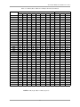
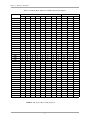
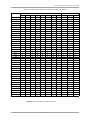
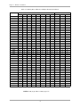
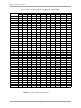
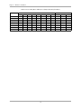
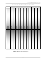
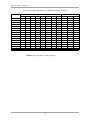
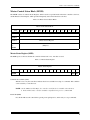
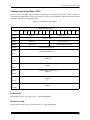
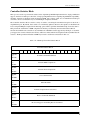
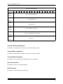
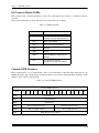
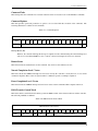
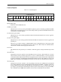
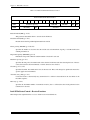
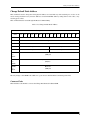
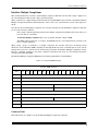
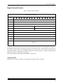
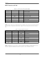
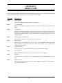
Controller Initialization Block (CIB)
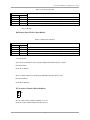
The CIB contains the actual values to use when initializing the controller. It may be located anywhere in Short I/O,
though it makes sense to place it after the MCE and before the Command Response Block.
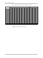
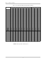
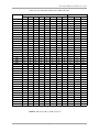
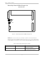
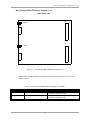
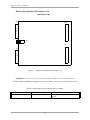
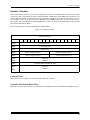
Table 3-20. Controller Initialization Block
Controller Initialization Block
Offst
15
14
13
0x00
12
11
10
9
8
7
6
Reserved
5
2
1
0
Special Network Options
0x02
Reserved
0x03
to
0x05
Ethernet Physical Address (Port 0)
(6 Bytes)
0x06
to
0x08
Ethernet Physical Address (Port 1)
(6 Bytes)
0x09
to
0x0B
Ethernet Physical Address (Port 2)
(6 Bytes)
0x0C
to
0x0E
Ethernet Physical Address (Port 3)
(6 Bytes)
0x10
3
Number of CQE Entries
0x01
0x0F
4
Controller Completion Level
Controller Completion Vector
Controller Error Level
Controller Error Vector
0x11
DMA Burst Count
0x12
Reserved
0x13
Offboard CRB Transfer Word
0x14
Offboard CRB Host Address (MSW)
0x15
Offboard CRB Host Address (LSW)
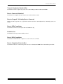
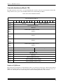
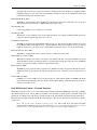
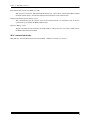
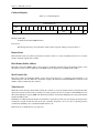
Number of CQE Entries
This field specifies the number of Command Queue entries to be used in the circular queue. Without using offboard
IOPBs, the maximum number ranges between 30 and 37. With offboard CQEs, this number can be increased to 151
(1812 / 12). Choosing the correct value is important to ensure maximum performance of the controller.
74