1
User Guide
®
Great
M inds
Think
C O M P U T E R S
.
N E T W O R K S
.
®
S O L U T I O N S
Viglen SX220 User Guide – MA-SX220-0A-01
Contents
1. Overview
5
Introduction
5
2. Chassis Specifications
Chassis Specification
Physical Specifications
Chassis Front Controls and Indicators
Front Panel Controls and Indicators
Chassis Back I/O Ports and Features
Power Supply
System Cooling
Security
Rack and Cabinet Mounting Options
Optional Peripherals
3. Motherboard Specifications
Server Board Features
Server Board Connectors and Component Location
Back panel Connectors
Processor
Memory
Add-in Board Slots
Video
SCSI Controller
IDE Controller
Network Controller
Network Connector and Status LEDs
Network Teaming Features
Adapter Fault Tolerance
Preferred Primary Adapter
Adaptive Load Balancing
Cisco Fast EtherChannel
Keyboard and Mouse
RJ-45 Serial Port
ACPI
Security
6
6
7
7
8
9
10
10
10
10
11
12
12
13
14
15
15
15
16
16
16
17
17
17
18
18
19
19
19
19
21
21
4. Assembling the System
26
Before You Begin
Installing the Server Board
Routing Cables
26
28
32
Viglen SX220 User Guide
1
Installing the Fan Assembly
Installing the Power Cord and Strain Relief Strap
Adding Components to the Server Board
Installing Peripherals
5. Installing the System in a Rack
34
35
36
41
51
Removing the Rails
Attach Inside Rails to Chassis
Attach Rail Brackets to Posts
Attach a Rail Assembly to a Front Bracket
Attach a Rail Assembly to a Rear Bracket
Install the Chassis on the Rails
52
52
53
54
55
55
6. Configuration Software and utility
57
Hot Keys
Power-On Self-Test (POST)
Using BIOS Setup
Setup Menu
Main Menu
Advanced Menu
Security Menu
Server Menu
Boot Menu
Exit Menu
Temporarily Changing the Boot Device Priority
Running the Adaptec SCSISelect Utility
When to Run the Adaptec SCSISelect Utility
Running the SCSISelect Utility
Configuring the Adaptec AIC-7899 SCSI Adapter
Running the Promise FastBuild Utility
Direct Platform Control (DPC) Console
Using the System Setup Utility
MultiBoot Options Add-in
Password Add-in
Options Button
SEL Manager Add-in
FRU Manager Add-in
SDR Manager Add-in
System Update Add-in
Platform Event Manager Add-in
Platform Event Paging Dialog
BMC LAN-Configuration Dialog
Platform Event Action Dialog
Emergency Management Port Dialog
Exiting the SSU
Platform Event Paging
2
Viglen SX220 User Guide
57
58
59
59
60
61
64
65
66
68
68
68
69
69
69
70
70
72
76
76
77
78
79
81
81
85
86
87
90
92
94
95
Software Updates
Software Update Package
Individual Updates
Upgrading the BIOS
Recovering the BIOS
96
96
98
99
99
7. Intel Server Control
104
About Intel Server Control
Managing Remote Servers
Server Management Tools
Client System Setup Utility
The Service Partition and Remote Diagnostics
DMI Explorer
Management Consoles
Connecting to a Remote Server
Paging an Administrator
Using the Intel Server Control Console
ISC Console Button Bar
Server Menu Options
View Menu Options
8. Solving Problems
105
106
107
110
111
111
112
113
115
116
117
118
119
121
Resetting the System
Initial System Start-up
After the System has been Running Correctly
More Problem Solving Procedures
Monitoring POST
Specific Problems and Corrective Actions
Problems with Network
Problems with Application Software
Bootable CD-ROM is not Detected
121
121
122
123
124
124
127
128
128
9. Technical Reference
129
Server Board Jumpers
Diagnostic LEDs
129
129
10. Regulatory & Integration Information
Product Regulatory Compliance
Electromagnetic Compatibility Notices
Replacing the Backup Battery
11. Equipment Log & Power Consumption
Equipment Log
134
134
135
136
137
137
Viglen SX220 User Guide
3
Current Usage
Calculating Power Consumption
Worksheet, Calculating DC Power Usage
Worksheet, Total Combined Power Used by the System
12. Appendix
139
139
140
141
142
Contacting Viglen
142
13. Notes
143
14. Viglen, EMC and the ‘CE’ mark
146
15. Copyrights and Trademarks
147
16. Suggestions
148
4
Viglen SX220 User Guide
1. Overview
Introduction
This manual describes the Viglen SX220 system and the SCB2 motherboard. The
motherboard is the most important part of your computer. It contains all of the CPU,
memory and graphics circuitry that makes the computer work.
The motherboard contains the very latest in CPU design, the Intel Pentium III
processors, which include MMX, Internet Streaming SIMD Extensions and Tualatin
technology. MMX technology adds a total of 57 instructions to the CPU, all of which
are designed to vastly improve both multimedia and communications on your PC.
SIMD Extensions add 70 new instructions enabling advanced imaging, 3D,
streaming audio and video, and speech recognition for an enhanced Internet
experience. Tualatin technology includes a smaller die size of 0.13 micron, resulting
in lower power consumption and lower heat output. The Level2 cache on die has
increased to 512K in size. The combination of the Intel Pentium III processors,
MMX, SIMD, Tualatin technology and Viglen expertise make this a formidable
computer.
This manual contains technical information about the Viglen SCB2 motherboard and
other hardware components inside your computer. If you are new to computers we
recommend that you read the user guide first. If you are an experienced computer
user this manual should provide all the information you will need to perform simple
upgrades and maintenance.
We hope that this manual is both readable and informative. If you have any
comments or suggestions about how we could improve the format then please fill out
the form at the back of the manual and send it to us.
Above all we hope that you enjoy using your Viglen computer.
Viglen SX220 User Guide
5
2. Chassis Specification
The SX220 system consists of the following major components:
•
The chassis and its subassemblies, device bays, and front bezel
•
A slim-line CD-ROM drive & Floppy Disk Drive
•
The power supply
•
The cooling system
•
SCB2 Motherboard & PCI riser cards
The major component of the kit is the chassis. It is important to become familiar with
the chassis both externally and internally and the security features it provides.
6
Viglen SX220 User Guide
Physical Specifications
The SX220 chassis is designed as a 2U 19” Rackmount unit. The server will be
supplied complete with a pair of industry standard 19” Rails, handles and all of the
necessary nuts and bolts.
Table 1: Physical Specifications
Specifications
Height
Width / Rackmount Height
Depth
Weight
89 mm
430 mm / 2U
648 mm
18 kg typical configuration
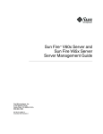
Chassis Front Controls and Indicators
The front panel controls and indicators are located behind the optional front bezel of
the system as shown in Figure 1. You can access the panel and the system
peripherals by grasping the bezel at its edges and gently pulling it towards you.
Figure 1: Chassis Front Controls and Indicators
A – Chassis handles
B – Drive bay (1-inch)
C – HDD activity/fault indicator
D – Flex bay (seventh HDD or
optional CDROM drive/FDD module)
E – Front panel indicator lights
F – RJ-45 serial port (PC-to-PC)
G – USB connectors 3 and 4
H – System controls
I – Tape drive bay
Viglen SX220 User Guide
7
Front Panel Controls and Indicators
Figure 2: Front Panel Controls and Indicators
A – NIC 1 activity LED
B – NIC 2 activity LED
C – System status LED
D – Fixed disk drive status LED
E – ID LED
F – ID button
G – NMI button (tool assisted)
H – Reset button
8
I – Power/sleep LED
J – Power button
K – FDD activity LED
L – CD-ROM activity LED
M – CD-ROM drive eject button
N – Manual CD-ROM drive eject button
O – FDD eject button
Viglen SX220 User Guide
Chassis Back I/O Ports and Features
The back panel provides connectors for the server board, slots for add-in cards, and
the power supply for the server. Figure 3 identifies the features of the back panel.
Figure 3: Chassis Back I/O Ports and Features
A – PCI card bracket (low profile)
B – RJ45 NIC 2 connector
C – Serial 1 port mounting hole
D – PCI card bracket (full-height)
E – AC power input (primary)
F – AC power input (redundant)
G – Power supply module,
redundant
H – Power supply module, primary
I – USB connector 2
J – RJ45 serial 2 port
K – PS/2* mouse/keyboard connector
L – RJ45 NIC 1 connector
M – SCSI connector
N – Video connector
O – USB connector 1
Viglen SX220 User Guide
9
Power Supply
The power supply consists of the power supply bay and one power supply module. A
second power supply module can be purchased to provide a redundant, 1+1 system.
With either configuration, the power supply provides 350 watts of power and is
designed to minimise EMI.
The power supply operates within the following voltage ranges and is rated as
follows:
100 - 120 V~ at 50/60 Hertz (Hz); 6.3A maximum
200 - 240 V~ at 50/60 Hz; 2.5A maximum
The power subsystem supports the implementation of remote management features,
including remote enable that permits power to be activated from a variety of sources.
System Cooling
The chassis includes two 80-mm non-hot-swappable system fans for cooling the
processor(s), hard drives, and add-in cards. A third fan may be added in the center
position to provide cooling redundancy for system components. The system fans are
mounted in a fan assembly located in the middle of the chassis to pull cooling air
through the chassis. The power supply contains a single fan for cooling.
Security
To help prevent unauthorised access to the system’s peripherals and control panel,
an optional key-locked front bezel can be used. The chassis also includes a
preinstalled intrusion switch that can be monitored by server management software.
When the cover is opened, a switch located on the front panel board transmits a
signal to the Baseboard Management Controller (BMC) on the server board.
Through server management software, the system can be programmed to respond
to an intrusion by powering down or by locking the keyboard. At the chassis level a
variety of security options are provided.
Rack and Cabinet Mounting Options
The SX220 chassis was designed to support 19” wide by up to 30” deep server
cabinets. The chassis comes equipped with a relay rack or cabinet mount kit that can
be configured to support front-mount or mid-mount 2-post racks and 4-post cabinets.
Viglen also provides an optional sliding rail kit that is used to mount the chassis into
a standard (19” by up to 30” deep) EIS 310D compatible server cabinet.
For mounting in a regular server cabinet, the front mount brackets are attached to
the front of the chassis, and a set of rear support brackets are attached to the back
end of the cabinet. This evenly distributes the server to prevent the mounting rails on
the cabinet from bending. Caution should be used in using the front mount-only
option. Even though the rail mount kit hardware was designed to support the weight
10
Viglen SX220 User Guide
of the system, some 2-post relay racks may not, causing the racks to fail. Only use
relay racks that are specifically designed to support the weight and stresses of a 2post front-mount only chassis.
Optional Peripherals
The SX220 server chassis provides six hard drive bays at the front of the chassis. An
optional seventh drive may be used in the flex bay. All hard drive bays may be
populated with a tray mounted 3½” hard disk drive. If a configuration requires the use
of a floppy disk drive and CDROM drive Floppy/CDROM module may be used in
place of the seventh hard drive in the flex bay. A tape drive bay is located below the
flex bay.
Hot-Swappable Hard Disk Drives
The SX220 server chassis can support up to seven tray-mounted SCA2, 3½” x 1”
and Ultra2/Ultra160 hard disk drives.
A major feature of the hot-swap bay is the backplane which powers down a drive
when a failure is detected and reported to the SCSI bus. When a new drive is
inserted, the power control waits a short time for the drive to become fully seated
and then applies power to the drive. The backplane provides signals to the control
panel to indicate failure status for each drive in the bay.
The chassis ships with six drive carriers for mounting the separately purchased hard
drives. For information on how to install these drives, refer to page 43.
Flex Bay
For those configurations that require a floppy drive and CD-ROM drive, the seventh
drive bay or “Flex Bay” will be configured as a peripheral bay by inserting the
Floppy/CDROM module. The Floppy/CDROM module is a 3½” floppy drive and a ½”
(12.7mm) slim-line CDROM drive mounted as a single unit in the peripheral bay. A
release latch allows for tool-less removal from the front of the server, however, the
Floppy/CDROM Module is not hot swappable. The system must be powered down
before the module is inserted or removed from the flex bay.
If the Flex Bay is used to house a SCA2 hard disk drive the bay will be hotswappable the same as the six other standard bays.
Viglen SX220 User Guide
11
3. Motherboard Specification
Server Board Features
Table 2: Server Board Features
Feature
Processor
Memory
Description
Dual processor slots supporting Intel® Pentium® III processors in
a Socket370 Flip Chip Pin Grid Array (FC-PGA) package.
Six dual inline memory module (DIMM) slots support:
•
Graphics
Video Memory
PCI bus
SCSI
Network
System I/O
Form Factor
12
SDRAM DIMMs: 133 MHz, ECC, registered, PC/133
compliant, 72-bit, 168-pin, gold contact, 3.3V. A 1U chassis
requires low-profile (LP) 1.2-inch DIMMs.
• Up to 6 GB of memory in a 2U chassis.
Integrated onboard ATI RAGE XL PCI 64 bit SVGA controller.
8 MB SDRAM of video memory
Two PCI riser slots capable of supporting three full-length, fullheight 64-bit/66-MHz PCI riser slots and three LP 64-bit/66-MHz
PCI riser slots.
Adaptec AIC- AIC7899W, supporting onboard Ultra160 (LVD)
Ultra-wide SCSI interfaces.
Dual on-board 10/100 Network Interface Controllers (NIC)
• One PS/2 keyboard/mouse port (6 pin DIN)
• One VGA video port (15 pin)
• Two USB ports
• One serial port (RJ-45)
• One SCSI port (SCSI server board only)
• Two NIC ports (RJ-45)
Server ATX form factor
Viglen SX220 User Guide
Server Board Connector and Component Locations
Figure 4: Server Board components
A – Speaker
B – ID LED
C – Battery
D – Diagnostic LEDs (POST code)
E – 66 MHz/64-bit PCI riser slot
F – A DIMM slots
G – I/O ports
H – ICMB connector
I – COM 1 serial header
J – Chassis intrusion connector
K – 66 MHz/64-bit PCI riser slot (LP)
L – USB 3 & 4 header
M – Sys fan 3 connector
N – CPU 2 fan connector
O – Secondary processor socket
P – Primary processor socket
Q – Sys fan 2 connector
R – CPU 1 fan connector
S – Sys fan 1 connector
T – Aux fan connector
U – Floppy drive connector
V – Fan module connector
W – Main power connector
X – Auxiliary signal connector
Y – Floppy/FP/IDE connector
Z – Alternate front panel connector
AA – ATA/IDE connector
BB – IPMB connector
CC – SSI front panel connector
DD – Configuration jumper block
EE – Not applicable on SX220
FF – SCSI connector
GG – Hard Disk Drive LED header
Viglen SX220 User Guide
13
Back Panel Connectors
Figure 5: Back Plane Connectors
A – USB 1 connector
B – Video connector
C – SCSI connector
D – NIC 2 RJ-45 connector
E – Green Status LED
F – Yellow Status LED
14
G – NIC 1 RJ-45 connector
H – Green Status LED
I – Yellow Status LED
J – PS/2 keyboard/mouse connector
K – RJ-45 serial port
L – USB 2 connector
Viglen SX220 User Guide
Processor
The SCB2 motherboard accommodates one or two Intel Pentium III processors with
512k cache in the FC-PGA2 package. This processor uses the 0.13 micron
technology and offers advanced performance. The processor external interface
operates at a maximum of 133 MHz.
Memory
The system board contains six 168-pin DIMM slots each supporting 72-bit ECC (64bit main memory plus ECC) registered SDRAM DIMMs (PC-133 compatible).
Memory is two-way interleaved and partitioned in three banks. You may install a
minimum of 128 MB (64MB x 2) and as much as 6 GB.
The controller automatically detects, sizes, and initialises the memory array,
depending on the type, size, and speed of the installed DIMMs, and reports memory
size and allocation to the server via configuration registers.
NOTE: Use DIMMs that have been tested for compatibility with the server board.
Contact your sales representative or dealer for a current list of approved
memory modules
Add-in Board Slots
The server board has two PCI riser slots, each capable of supporting 64-bit/66-MHz
PCI riser cards. PCI features:
•
Bus speed up to 66 MHz
•
32 bit memory addressing
•
5 V/3.3 V signaling environment
•
Burst transfers of up to 512 Mbps
•
8, 16, 32, or 64-bit data transfers
•
Plug and Play ready
•
Parity enabled
Viglen SX220 User Guide
15
Video
The SCB2 motherboard uses an ATI RAGE XL PCI graphics accelerator with 8 MB
of video SDRAM that supports all standard IBM VGA modes. The embedded SVGA
video subsystem supports:
•
Pixel resolutions up to 1600 x 1200 under 2D and 1024 x 768 under 3D
•
CRT and LCD monitors up to 100 Hz vertical refresh rate
The server board supports disabling of the onboard video through the BIOS setup
menu or when a plug in video card is installed in any of the PCI slots.
SCSI Controller
The server board includes an embedded Adaptec AIC-7899W controller providing
dual Ultra160 Low Voltage Differential (LVD) SCSI channels.
The SCSI bus is terminated on the server board with active terminators that cannot
be disabled. The onboard device must always be at one end of the bus. The device
at the other end of the cable must also be terminated. LVD devices generally do not
have termination built-in and need to have a termination source provided. Non-LVD
devices generally are terminated through a jumper or resistor pack on the device
itself.
IDE Controller
The system includes a single channel enhanced IDE 32 bit interface controller for
intelligent disk drives with disk controller electronics onboard. The controller has a
connector located on the system board that supports a master and a slave device.
The device controls:
16
•
PIO and DMA transfer modes
•
DMA-33 capable
•
Mode 4 timings
•
Transfer rates up to 33 MB/s
•
Buffering for PCI/IDE burst transfers
•
Master/slave IDE mode
•
Up to two devices.
Viglen SX220 User Guide
Network Controller
NOTE: To ensure EMC product regulation compliance, the system must be used
with a shielded LAN cable.
The server board uses two Intel® 82550PM Fast Ethernet Controllers and supports
two 10Base-T/100Base-TX network subsystems. The 82550 PM controller supports
the following features:
•
32-bit PCI, CardBus master interface
•
Integrated IEEE 802.3 10Base-T and 100Base-TX compatible PHY
•
IEEE 820.3u auto-negotiation support
•
Chained memory structure similar to the 82559, 82558, 82557 and 82596
•
Full duplex support at both 10 Mbps and 100 Mbps operation
•
Low power +3.3 V device
•
IP checksum off-loading
The SX220 server NIC 1 can be used as both a network interface and server
management interface.
NIC Connector and Status LEDs
The 82550 controller drives LEDs on the network interface connector that indicates
link/activity on the LAN and 10- or 100-Mbps operation. The green LED indicates
network connection when on and TX/RX activity when blinking. The yellow LED
indicates 100-Mbps operation when lit.
Network Teaming Features
NOTE: Using both on-board NICs in a team does not allow the use of NIC 1 for
server management access. To support both network teaming features and
server management features, a third NIC must be added and teamed to NIC
2.
The network controller provides several options for increasing throughput and fault
tolerance when running Windows NT 4.0, Windows 2000, NetWare 4.1x or newer, or
Linux:
•
Adapter Fault Tolerance (AFT) - provides automatic redundancy for your
adapter. If the primary adapter fails, the secondary takes over. AFT works
with any hub or switch.
Viglen SX220 User Guide
17
•
Adaptive Load Balancing (ALB) - creates a team of 2 - 8 adapters to increase
transmission throughput. Also includes AFT. Works with any 10Base-TX or
100Base-TX switch.
•
Fast EtherChannel (FEC) or Intel® Link Aggregation - creates a team of up to
8 adapters to increase transmission and reception throughput. Also includes
AFT. Requires a FEC-enabled switch.
To set up an option, read the instructions in the Windows NT 4.0 or NetWare 4.1x
readme files.
General Configuration Notes
1. Windows NT versions prior to 4.0 do not support Adapter Teaming options.
2. Adapter Teaming options require NT 4.0 with Service Pack 4.0 or Service Pack
3.0 and the Windows Hot Fix.
3. In Windows NT, teaming options cannot be implemented on adapters that have
been configured for VLANs. NetWare can support teaming options and VLANs on
the same adapters.
Adapter Fault Tolerance
Adapter Fault Tolerance (AFT) is a simple, effective, and fail-safe approach to
increase the reliability of server connections. AFT gives you the ability to set up link
recovery to the server adapter in case of a cable, port, or network interface card
failure. By assigning two server adapters as a team, AFT enables you to maintain
uninterrupted network performance.
AFT is implemented with two server adapters: a primary adapter and a backup, or
secondary, adapter. During normal operation, the backup will have transmit disabled.
If the link to the primary adapter fails, the link to the backup adapter automatically
takes over.
Preferred Primary Adapter
With multiple adapters installed, you can specify one as the Preferred Primary
adapter. For example if you have a server with a PRO/1000 server adapter as the
primary adapter and a PRO/100+ adapter as the secondary, you could configure the
PRO/1000 server adapter to be the preferred primary. In this scenario, if the
PRO/1000 server adapter fails, the PRO/100+ will take over. Then when the
PRO/1000 server adapter is replaced, it will automatically revert to being the primary
adapter in the team.
If a Preferred Primary is not selected, PROSet will attempt to select the best adapter,
based on adapter model and speed.
18
Viglen SX220 User Guide
Mixed Adapter Teaming
AFT supports up to eight server adapters per team, in any mix.
Adaptive Load Balancing
Adaptive Load Balancing (ALB) is a simple and efficient way to increase your
server’s transmit throughput. With ALB you group server adapters in teams to
provide an increased transmit rate (up to 8 Gbps) using a maximum of eight
adapters. The ALB software continuously analyses transmit loading on each adapter
and balances the rate across the adapters as needed. Adapter teams configured for
ALB also provide the benefits of AFT. Receive rates remain at 100 Mbps or 1 Gbps
depending on the primary adapter’s capability.
To use ALB, you must have 2-8 server adapters installed in your server or
workstation and linked to the same network switch.
Cisco Fast EtherChannel
Fast EtherChannel (FEC) is a performance technology developed by Cisco to
increase your server’s throughput. Unlike ALB, FEC can be configured to increase
both transmission and reception channels between your server and switch. FEC
works only with FEC-enabled switches, such as the Catalyst 5000 series. With FEC,
as you add adapters to your server, you can group them in teams to provide up to 18
Gbps at full duplex, with a maximum of 8 server adapters. The FEC software
continuously analyses loading on each adapter and balances network traffic across
the adapters as needed. Adapter teams configured for FEC also provide the benefits
of AFT.
To use FEC, you must have 2, 4, or 8 server adapters installed in your server and
linked to the same FEC-enabled Cisco switch.
Keyboard and Mouse
The keyboard/mouse controller is PS/2-compatible. If specified through the System
Setup Utility (SSU), the server may be locked automatically if there is no keyboard or
mouse activity for a predefined length of time. Once the inactivity (lockout) timer has
expired, the keyboard and mouse do not respond until the previously stored
password is entered. A Y-cable can be used if both a PS/2 mouse and keyboard are
required at the same time.
RJ-45 Serial Port
The rear RJ-45 serial port is a fully functional COM port that supports any standard
serial device and provides support for serial concentrators, which typically support
RJ45 serial connectors. For server applications that use a serial concentrator to
access the server management features of the baseboard, a standard 8-pin CAT-5
cable from the serial concentrator is plugged directly into the rear RJ45 serial port.
Viglen SX220 User Guide
19
The 8 pins of the RJ45 connector can be configured to match either of two pin-out
standards used by serial port concentrators. To accommodate either standard, the
J6A2 jumper block located directly behind the rear RJ45 serial port must be
jumpered appropriately according to which standard is desired.
NOTE: By default, as configured in the factory, the SCB2 baseboard will have the
rear RJ45 serial port configured to support a DSR signal.
For serial concentrators that require a DCD signal, the J6A2 jumper block must be
configured as follows: The DCD jumper in position 2 and 3 and the DSR jumper in
position 2 and 3. Pin 1 on the jumper is denoted by an arrow directly next to the
jumper block. See Figure 9 on page 129 for the jumper block pin-out of this
configuration.
Figure 6: Jumper Block Pin-out
For serial concentrators that require a DSR signal, the J6A2 jumper block must be
configured as follows: The DSR jumper in position 1 and 2 and the DCD jumper in
position 1 and 2. An arrow directly next to the jumper block denotes pin 1 on the
jumper. See Figure 7.
Figure 7: Jumper Clock Pin-out
For those server applications that require a DB9 type of serial connector, an 8-pin
RJ45-to-DB9 adapter must be used. The following table defines the pin-out required
for the adapter to provide RS232 support.
Table 3: Pin-out required for an RS-232 support
RJ45
1
2
3
4
5
6
7
8
20
Signal
Request to Send
Data Terminal Ready
Transmitted Data
Signal Ground
Ring Indicator
Received Data
DCD or DSR
Clear To Send
Abbreviation
RTS
DTR
TD
SGND
RI
RD
DCD/DSR
CTS
DB9
7
4
3
5
9
2
1 OR 6
8
Viglen SX220 User Guide
NOTE: The RJ45-to-DB9 adapter should match the configuration of the serial device
used. One of two pin-out configurations are used depending on whether the
serial device requires a DSR or DCD signal. The final adapter configuration
should also match the desired pin-out of the RJ45 connector, as it can also
be configured to support either DSR or DCD.
For systems configured with both a front and rear RJ45 serial connectors,
the adapters used for the rear port cannot be used with the front port, as the
pin-out for both RJ45 ports are different. For example, modem applications
typically use DCD. In this case the user would use a DCD-configured
adapter and set the jumper block as shown in Figure 6.
ACPI
The SCB2 server motherboard supports the Advanced Configuration and Power
Interface (ACPI) as defined by the ACPI 1.0 and PC97 specifications. An ACPI
aware operating system can put the system into a state where the hard drives spin
down, the system fans stop, and all processing is halted. However, the power supply
will still be on and the processors will still be dissipating some power, so the power
supply fans will still run.
The boards sleep states s0, s1, s4, and s5:
•
s0: Normal running state.
•
s1: Processor sleep state. No context will be lost in this state and the
processor caches will maintain coherency.
•
s4: Hibernate or Save to Disk: The memory and machine state are saved to
disk. Pressing the power button or other wakeup event will restore the system
state from the disk and resume normal operation. This assumes that no
hardware changes have been made to the system while it was off.
•
s5: Soft off: Only the RTC section of the CSB and the BMC are running in this
state. No context is saved by the OS or hardware.
CAUTION!
The system is off only when the AC power is disconnected.
Security
Intrusion Switch Monitoring
To help prevent unauthorised entry or use of the server, Intel® Server Control server
management software monitors the chassis intrusion switch if one is installed.
Opening an access cover will transmit an alarm signal to the server board, where
BMC firmware and server management software process the signal. The system can
Viglen SX220 User Guide
21
be configured through ISC to respond to an intrusion a number of ways, including
powering down or locking the keyboard.
Software Locks
The BIOS Setup and the System Setup Utility (SSU) provide a number of security
features to prevent unauthorised or accidental access to the system. Once the
security measures are enabled, you can access the system only after you enter the
correct password(s). For example:
•
Enable the keyboard lockout timer so that the server requires a password to
reactivate the keyboard and mouse after a specified time out period.1 to 120
minutes.
•
Set and enable a supervisor password.
•
Set and enable a user password.
•
Set secure mode to prevent keyboard or mouse input and to prevent use of
the front panel reset and power switches.
•
Activate a hot key combination to enter secure mode quickly.
•
Disable writing to the diskette drive when secure mode is set.
•
Disable access to the boot sector of the operating system hard disk drive.
Using Passwords
You can set the user password, the supervisor password, or both passwords. If only
the user password is set, you:
•
Must enter the user password to enter BIOS Setup or the SSU.
•
Must enter the user password to boot the server if Password on Boot is
enabled in either the BIOS Setup or SSU.
•
Must enter the user password to exit secure mode.
If only the supervisor password is set, you:
•
Must enter the supervisor password to enter BIOS Setup or the SSU.
•
Must enter the supervisor password to boot the server if Password on Boot is
enabled in either the BIOS Setup or SSU.
•
Must enter the supervisor password to exit secure mode.
If both passwords are set, you:
22
Viglen SX220 User Guide
•
May enter the user password to enter BIOS Setup or the SSU. However, you
will not be able to change many of the options.
•
Must enter the supervisor password if you want to enter BIOS Setup or the
SSU and have access to all of the options.
•
May enter either password to boot the server if Password on Boot is enabled
in either the BIOS Setup or SSU.
•
May enter either password to exit secure mode.
Secure Mode
Configure and enable the secure boot mode by using the SSU. When secure mode
is in effect:
•
You can boot the server and the operating system will run, but you must enter
the user password to use the keyboard or mouse.
•
You cannot turn off system power or reset the server from the front panel
switches.
Secure mode has no effect on functions enabled via remote server management or
power control via the watchdog timer.
Taking the server out of secure mode does not change the state of system power.
That is, if you press and release the power switch while secure mode is in effect, the
system will not be powered off when secure mode is later removed. However, if the
front panel power switch remains depressed when secure mode is removed, the
server will be powered off.
Summary of Software Security Features
The table below lists the software security features and describes what protection
each offers. In general, to enable or set the features listed here, you must run the
SSU and go to the Security Subsystem Group, menu. The table also refers to other
SSU menus and to the Setup utility.
Table 4: Software Security Features
Feature
Description
Secure mode
How to enter secure mode:
•
Setting and enabling passwords automatically places the system in
secure mode.
•
If you set a hot-key combination (through Setup), you can secure the
system simply by pressing the key combination. This means you do
not have to wait for the inactivity time-out period.
When the system is in secure mode:
Viglen SX220 User Guide
23
The server can boot and run the operating system, but mouse and
keyboard input is not accepted until the user password is entered.
At boot time, if a CD is detected in the CD-ROM drive or a diskette in drive
A, the system prompts for a password. When the password is entered, the
server boots from CD or diskette and disables the secure mode.
If there is no CD in the CD-ROM drive or diskette in drive A, the server
boots from drive C and automatically goes into secure mode. All enabled
secure mode features go into effect at boot time.
Disable writing
to diskette
Set a time out
period so that
keyboard and
mouse input
are not
accepted
Also, screen
can be
blanked, and
writes to
diskette can
be inhibited
Control access
to using the
SSU: set
supervisor
password
To leave secure mode: Enter the correct password(s).
In secure mode, the server will not boot from or write to a diskette unless a
password is entered.
To write protect access to diskette whether the server is in secure mode or
not, use the Setup main menu, Floppy Options, and specify Floppy Access
as read only.
Specify and enable an inactivity time out period of from 1 to 120 minutes.
If no keyboard or mouse action occurs for the specified period, attempted
keyboard and mouse input will not be accepted.
The monitor display will go blank, and the diskette drive will be write
protected (if these security features are enabled through Setup).
To resume activity: Enter the correct password(s).
To control access to setting or changing the system configuration, set a
supervisor password and enable it through Setup.
If both the supervisor and user passwords are enabled, either can be used
to boot the server or enable the keyboard and/or mouse, but only the
supervisor password will allow Setup to be changed.
To disable a password, change it to a blank entry or press CTRL-D in the
Change
Password menu of the Supervisor Password Option menu found in the
Security
Subsystem Group.
Control access
to the system
other than
SSU: set user
password
24
To clear the password if you cannot access Setup, change the Clear
Password jumper (see Chapter 9).
To control access to using the system, set a user password and enable it
through
Setup.
To disable a password, change it to a blank entry or press CTRL-D in the
Change
Viglen SX220 User Guide
Password menu of the User Password Option menu found in the Security
Subsystem Group.
Boot without
keyboard
Specify the
boot sequence
To clear the password if you cannot access Setup, change the Clear
Password jumper (see Chapter 9).
The system can boot with or without a keyboard. During POST, before the
system completes the boot sequence, the BIOS automatically detects and
tests the keyboard if it is present and displays a message.
The sequence that you specify in setup will determine the boot order. If
secure mode is enabled (a user password is set), then you will be
prompted for a password before the server fully boots. If secure mode is
enabled and the “Secure Boot Mode” option is also enabled, the server
will fully boot but will require a password before accepting any keyboard or
mouse input.
Viglen SX220 User Guide
25
4. Assembling the System
This chapter will give a step-by-step guide of installing the server board and the main
components in the system. It will give information on how to add add-in cards and
upgrade processors and memory along with other relevant information that may be
of important use.
Before You Begin!
Before you start the assembly process you will need to have the right tools available
to you and you will need to make sure you follow certain basic safety precautions.
Tools and Supplies Needed
Before beginning your work, make sure you have the following tools and supplies
available:
•
•
•
Phillips (cross head) screwdriver (#2 bit)
Anti-static wrist strap (recommended)
Installation / Assembly Safety Instructions
System components must be installed in the order presented below. If installed in a
different order, component damage may occur.
CAUTION!
Integration / servicing of this chassis sub assembly shall be performed only by
technically qualified persons.
Follow these guidelines to meet and maintain safety and product regulatory
requirements when integrating this chassis subassembly.
WARNING!
Do not attempt to modify or use the supplied AC power cord(s) if it is not the exact
type required.
The power supply cords are the main disconnect device to mains (AC power). The
socket outlet shall be installed near the equipment and shall be readily accessible.
26
Viglen SX220 User Guide
Warnings and Cautions!
These warnings and cautions apply whenever you remove the access cover to
access components inside the server. Only a technically qualified person should
integrate and configure the server.
Before removing the access cover for any reason, observe these safety guidelines.
•
Turn off all peripheral devices connected to the server.
•
Turn off the server by pressing the power button on the front of the chassis.
Then unplug the AC power cord from the chassis or wall outlet.
•
Label and disconnect all peripheral cables and all telecommunication lines
connected to I/O connectors or ports on the back of the chassis.
•
Provide some electrostatic discharge (ESD) protection by wearing an
antistatic wrist strap attached to chassis ground—any unpainted metal
surface—when handling components.
WARNING!
The power button on the front panel DOES NOT turn off the AC power. To remove
power from server, you must unplug the AC power cord(s) from the wall outlet or the
chassis.
WARNING!
Hazardous electrical conditions may be present on power, telephone, and
communication cables. Turn off the server and disconnect the power cords,
telecommunications systems, networks, and modems attached to the server before
opening it. Otherwise, personal injury or equipment damage can result.
WARNING!
Do not open the power supply, as there is risk of electric shock and burns from high
voltage and rapid overheating. Refer servicing of the power supply to qualified
technical personnel.
Viglen SX220 User Guide
27
Installing the Server Board
Installing the server board consists of the following steps:
•
Removing the cover, Riser cards and fan assembly.
•
Mounting the server board in the chassis.
•
Cabling the server board to the other chassis components.
•
Adding processors and memory to the server board.
•
Replacing riser cards, fan assembly and the top cover.
Removing the Cover
1. While pressing the blue latch button (A) with your left thumb, slide the top cover
back using the heal of your right hand on the blue pad.
NOTE: A non-skid surface or a stop behind the chassis may be needed if attempting
to remove the top cover on a flat surface.
2. Set the cover aside and away from the immediate work area.
Figure 8: Removing the Cover
Removing the Riser Cards
1. Grasp riser card (A) at both ends (C) of the EMI shield.
28
Viglen SX220 User Guide
2. Lift straight up and remove it from the chassis.
3. Insert your finger in the plastic loop on riser card (B).
4. Pull straight up and remove it from the chassis.
5. Discard the protective foam blocks.
Figure 9: Removing the Riser Cards
Removing the Fan Assembly
1. At the end of the fan assembly closest to the chassis centerline, lift up on tab (A).
2. While lifting up on the tab, slide the fan assembly toward the chassis centerline
(B) until it releases from the chassis.
3. Lift the fan assembly out of the chassis.
Viglen SX220 User Guide
29
Figure 10: Removing the Fan Assembly
Installing the Server Board
1. Ensure that the Mylar insulator sheet is seated securely over the standoffs, is
laying flat on the chassis floor, and that the edge of the sheet is seated below the
studs in the rear chassis wall.
2. Remove the server board from its packaging and antistatic bag.
3. While placing the board on the chassis standoffs, carefully position the board I/O
connectors in the rear chassis I/O openings.
4. Adjust board position so that the two mounting holes near the board edges rest
securely on the two corresponding shouldered standoffs.
NOTE: The three holes on the server board used to mount the board to the standoffs
have white circles around them.
5. Attach the board to the chassis using the three thumbscrews shipped in the
chassis accessory kit.
30
Viglen SX220 User Guide
Figure 11: Attaching the Server Board
Viglen SX220 User Guide
31
Routing Cables
Figure 12: Routing Cables
1. Route the backplane power cable (A) from the power supply to the backplane
board and connect it to the white 6-pin connector.
2. Route the server board power cable (B) from the power supply to the cable clip
and connect it to the white 24-pin connector on the server board. Firmly press the
two connectors together until they are fully seated.
3. If you are not installing a tape drive, coil the tape drive power cable, wire tie the
coil, and place it on the floor.
4. Route the auxiliary signal cable (I) from the power supply to the server board and
connect it to 5-pin auxiliary signal connector.
32
Viglen SX220 User Guide
5. Connect the end of the flex circuit cable (C) labeled to the floppy/front panel/IDE
connector on the server board. Route the cable to the backplane board and
connect the opposite cable end to the matching connector on the backplane.
CAUTION!
After connection of cable (C) in step 5, ensure that each cable connector is properly
seated in the board connector. The connector should be parallel to its board
connector and not cocked to one side. If in doubt, remove, reinsert, and recheck.
6. Locate the end of the SCSI ribbon cable (I) that is labeled baseboard. Connect
that end to the SCSI connector on the server board. Route the cable to the
backplane board and connect it to the matching connector on the backplane
board.
7. Route the backplane power cable (A) from the power supply to the backplane
board and connect it to the white 6-pin connector.
8. Connect the front panel cable (E) to the front panel board. Insert the cable in the
cable clip (**), route it to the backplane, and connect it to the matching connector.
9. Connect the USB cable (F) to the USB connector on the server board. Route the
cable along the chassis floor at the bottom of the chassis sidewall (*). Connect it
to the front panel board.
10. Connect the system fan cables (G) to their server board connectors.
11. If you have installed a tape drive, connect the tape drive power cable (D) to the
drive.
Viglen SX220 User Guide
33
Installing the Fan Assembly
CAUTION!
When installing the fan assembly, avoid pinching cables routed in the area.
1. Ensure the USB cable is routed in the corner where the chassis floor meets the
sidewall.
2. Position the fan assembly as shown in Figure 14 and lower it to the chassis floor.
3. While pressing down on the fan assembly, slide it (A) toward the chassis
sidewall.
4. Check for the following:
•
The floor tabs have engaged the holes in the bottom of the fan assembly.
•
The latch tab (B) has engaged the chassis slot and locked the fan
assembly in place.
Figure 13: Installing the Fan Assembly
5. Connect the fan power cables to the server board at the system fan connectors
(Figure 14).
34
Viglen SX220 User Guide
Figure 14: System Fan Connectors
6. Connect the USB cable to the 10-pin USB connector on the server board (Figure
4, Position L on page 13).
Installing the Power Cord and Strain Relief Strap
NOTE: If you will be placing your server in a rack, wait to install the power cord until
after the server is in the rack.
1. Insert the expansion nipple (A) of the strain relief strap into the chassis hole.
2. Plug the power cord into the power supply but not into the power source.
3. Insert the power cord into the plastic loop (B) of the strain relief.
4. Pull the plastic band (C) until it tightens around the power cord.
To release the plastic loop and free the cord, squeeze the release lever (D).
Figure 15: Installing the Power Cord
Viglen SX220 User Guide
35
Adding Components to the Server Board
After installing the server board, you must add the desired number of processors and
memory DIMMs.
NOTE: Once the server board and its components are installed, you are done
assembling the system unless you have optional peripherals or add-in
cards you wish to install. If you need to install these components, continue
on to the next section. Otherwise, install the cover and bezel and continue
on to Chapter 5, “Installing the System in a Rack” found on page 51.
Installing Processors
1. Observe the safety and ESD precautions at the beginning of this chapter.
2. Raise the locking bar on the socket.
3. Observe the safety and ESD precautions at the beginning of this chapter.
4. Raise the locking bar on the socket.
Figure 16 Raising the Locking bar on the socket
5. Aligning the pins of the processor with the socket, insert the processor into the
socket.
6. Lower the locking bar completely.
36
Viglen SX220 User Guide
Figure 17: Inserting the Processor
7. Following the instructions packaged with the applicator, apply thermal grease to
the processor.
8. Position the heat sink slot (2) above the socket/processor slot (3).
9. Aligning the raised metal surfaces, place the heat sink on top of the processor.
10. Install the heat sink clip with pin (1) inserted into slot (2).
Viglen SX220 User Guide
37
Figure 18: Installing the Heatsink
A. Heat sink retention clip
B. Heat sink
C. Socket and processor
CAUTION!
Use care when closing the locking lever—do it slowly.
11. Slowly close the locking lever (A) until it contacts tab (B), see Figure 19.
38
Viglen SX220 User Guide
Figure 19: Locking Heatsink Lever
12. Install the fan on the processor heat sink making sure that it is seated flat on the
heatsink.
13. Connect the fan to (A) if it is on the primary processor or to (B) if it is on the
secondary processor.
Figure 20: Processor Fan Connectors
Viglen SX220 User Guide
39
Install the Processor Terminator
If you are installing only one processor, you must install a terminator in the
secondary processor socket (A). If you are installing two processors, skip this
section.
1. Raise the locking bar (B) on the socket.
2. Aligning the two corner marks on the terminator with the handle-side of the
socket (C), insert the terminator into the socket.
Lower the locking bar completely (D).
Figure 21: Installing the Processor Terminator
Memory
Only PC-133 compliant SDRAM is supported by the SX220 server board. Install from
128 MB to 6 GB of registered, ECC memory, using up to six DIMMs.
DIMMs must be installed in pairs and in the following order: 1a and 1b, 2a and 2b, 3a
and 3b.
Installed DIMMs must be the same speed and must all be registered. For a list of
supported memory, call your service representative.
40
Viglen SX220 User Guide
Figure 22: Installing DIMMs
Installing Peripherals
Peripherals and add-in cards are not included in your system and must be
purchased separately. The following sections describe how to install PCI add-in
cards, hard disk drives, a CD-ROM drive/floppy disk, and a tape drive.
Installing a PCI Card on a Riser Card
The riser card nearest the chassis sidewall supports three Low Profile (LP) PCI addin cards. The riser card on the chassis centerline supports three full-length, fullheight add-in cards or three LP cards (an LP card must be equipped with a standard
full-height PCI mounting bracket).
NOTE: Add-in cards must be installed on a riser card while the riser card is removed
from the chassis.
1. Open the retainer clip (A) and remove the filler panel from the rear retention
bracket (B) of the riser card.
2. Insert the PCI card edge connector in the riser PCI slot (D) while aligning the end
of the PCI card bracket in opening (C).
Viglen SX220 User Guide
41
3. Firmly push the PCI card connector into the riser card slot until it is fully seated.
4. Close the retainer clip (A). Ensure the clip is latched.
Figure 23: Installing a PCI card of the riser
Installing a Riser Card on the Server Board
1. Insert the riser card connector into the server board slot while aligning the tabs on
the rear retention bracket with the holes in the chassis.
CAUTION!
Press the riser card straight down into the slot. Tipping it into the slot while installing
it may damage the riser card or slot.
2. Firmly press the riser card straight down until it is fully seated in the server board
slot.
42
Viglen SX220 User Guide
Figure 24: Installing a Riser Card
Installing a Hard Drive
The server can support up to seven hot swappable hard drives: six hard drives in the
drive bays, plus one in the flex bay.
CAUTION!
To allow proper airflow and server cooling, all drive bays must contain either a carrier
with a hard drive installed or a carrier with an air baffle installed.
1. If present, remove the front bezel.
2. If the drive carrier is installed in the drive bay, remove it.
3. Remove the air baffle (Figure 25, A) from the drive carrier by removing the four
screws (B) from the slide track (C).
4. Store the air baffle for future reinstallation in the event you must operate your
server without a drive in one of the bays.
Viglen SX220 User Guide
43
Figure 25: Hard Drive Carrier
5. Remove the hard drive from its wrapper and place it on an anti-static surface.
6. Set any jumpers and/or switches on the drive according to the drive
manufacturer’s instructions.
7. With the drive circuit-side-down (Figure 26, A), position the connector end (E) so
that it is facing the back of the carrier (B).
8. Align the holes in the drive to the holes in the drive carrier slide track (C), insert
the screws (D) that you previously removed, and attach the carrier to the drive.
Figure 26: Installing the Hard Drive
9. Slide the carrier/drive all the way into the drive bay with the retention lever in the
fully open position.
10. Push the retention lever closed to secure the carrier/drive in the bay.
44
Viglen SX220 User Guide
11. Reinstall a carrier/air baffle in any bays where you are not installing a
carrier/drive.
Installing a CD-ROM Drive/FDD Module
The SX220 server is supplied with a CD-ROM drive and a floppy disk drive already
installed in the Flex Bay. The blow steps will help you to re-install the unit if it has
been removed to make way for an additional SCSI hard disk drive.
1. Remove the filler panel and plug from the front of the chassis.
2. Ensure the handle bar (A) on the front of the module is rotated to the down
position.
3. Insert the module into the flex bay and slide it back until you feel the connectors
touch.
4.
With your thumbs positioned above the handle bar indentations (B), push the
module in until it locks in place.
Figure 27: Installing a CDROM/FDD Module
Installing a Tape Drive
You may purchase a tape drive and install it in the 3.5-inch drive bay using the
carrier provided. SCSI tape drives are recommended due to the cable length
required. If you install an IDE tape drive, you must install an IDE add-in controller
card. The cable routing will be similar to what is shown for a SCSI tape drive.
Viglen SX220 User Guide
45
NOTE: Using the legacy IDE connector on the SCB2 server board to support an IDE
peripheral device in the SX220 server is not a supported configuration.
Using this connector in the SX220 server may produce unreliable operation
of the IDE device and may result in data loss.
If you install a SCSI tape drive, you can connect it one of two ways:
•
To the on-board SCSI controller. This requires that you connect the backplane
to an add-in RAID or SCSI controller.
•
To an add-in SCSI controller board. This allows you to leave the backplane
connected to the on-board SCSI controller.
Mounting the Tape Drive
1. Remove the chassis cover.
2. Remove the blank panel from the bay.
3. Push on the retainer clip at the rear of the carrier (A) to release it from the
chassis.
4. Remove the carrier by sliding it toward the front of the chassis.
5. Set any jumpers and/or switches on your tape drive (B) according to the drive
manufacturer’s instructions.
6. Install the tape drive in the carrier.
7. Insert the carrier/drive assembly in the empty bay and slide it toward the rear of
the chassis until the retainer clip latches.
Figure 28: Mounting a Tape Drive
46
Viglen SX220 User Guide
CAUTION!
Carefully route cables to minimise airflow blockage and cooling problems.
Suggested Tape Drive Cabling
A peripheral power cable (4-pin connector) is included in the cable output from the
power supply.
Route and connect to the tape drive before the SCSI cable is installed.
Connecting to the On-board SCSI Controller
1. Obtain a SCSI cable with an unfolded length of 26-inches.
2. Flatten the cable and fold it in half beginning about 1-inch from the tape drive end
(see Figure 29, A). Continue folding for a distance of about 10-inches.
3. Fold the cable in half again and secure with electrical tape.
4. Connect the cable to the tape drive (see Figure 30, A) and carefully route the
folded and taped section on the chassis floor between the fan assembly (C) and
the tape drive (A).
5. Connect the cable to the on-board SCSI controller at connector (B).
Because the on-board SCSI controller is now unavailable, you will need to install a
PCI add-in card that provides RAID or SCSI control and connect it to the backplane.
Figure 29: SCSI Cable Length Required
Viglen SX220 User Guide
47
Figure 30: Onboard SCSI Connector
Connecting to a SCSI Controller on a Full-height PCI Card
1. Obtain a SCSI cable with an unfolded length of 26-inches.
2. Flatten the cable and fold it in half beginning about 1-inch from the tape drive end
(see Figure 29, A). Continue folding for a distance of about 10-inches.
3. Fold the cable in half again and secure with electrical tape.
4. Connect the cable to the tape drive (see Figure 31, A) and carefully route the
folded and taped section on the chassis floor between the fan assembly (C) and
the tape drive (A).
5. Connect the cable to the SCSI controller (B) on the full-height PCI card.
Figure 31: Connecting to a Full Height PCI SCSI Controller
48
Viglen SX220 User Guide
Connecting to a SCSI Controller on a Low Profile PCI Card
1. Obtain a SCSI cable with an unfolded length of 26-inches.
2. Flatten the cable and fold it in half for the full length, leaving about 1-inch at each
end (see Figure 32).
3. Fold the cable in half again and secure with electrical tape.
4. Connect the cable to the tape drive (see Figure 33, A) and carefully route the
folded and taped section on the chassis floor between the fan assembly (C) and
the tape drive (A).
5. Connect the cable to the SCSI controller (B) on the low-profile PCI card.
Figure 32: SCSI Cable Length Required
Figure 33: Connecting to a half Height PCI SCSI Controller
Installing a COM 1 port in the Rear I/O
Using a standard DH-10 to DB-9 COM cable, you may install a COM 1 port in the
opening provided in the rear I/O (see Figure 3, C, on page 9). Connect the other end
to the COM 1 serial port header on the server board (see Figure 4 on page 13)
Viglen SX220 User Guide
49
Installing the Bezel
Place the bezel between the chassis handles and push it toward the front of the
chassis until it snaps into place.
Figure 34: Installing the Front Bezel
50
Viglen SX220 User Guide
5. Installing the System in a Rack
CAUTION!
ANCHOR THE EQUIPMENT RACK: The equipment rack must be anchored to an
unmovable support to prevent it from falling over when one or more servers are
extended in front of it on slide assemblies. The equipment rack must be installed
according to the manufacturer's instructions. You must also consider the weight of
any other device installed in the rack.
MAIN AC POWER DISCONNECT: You are responsible for installing an AC power
disconnect for the entire rack unit. This main disconnect must be readily accessible,
and it must be labeled as controlling power to the entire unit, not just to the server(s).
GROUNDING THE RACK INSTALLATION: To avoid the potential for an electrical
shock hazard, you must include a third wire safety grounding conductor with the rack
installation. If server power cords are plugged into AC outlets that are part of the
rack, then you must provide proper grounding for the rack itself. If server power
cords are plugged into wall AC outlets, the safety grounding conductor in each power
cord provides proper grounding only for the server. You must provide additional,
proper grounding for the rack and other devices installed in it.
OVER CURRENT PROTECTION: The server is designed for an AC line voltage
source with up to 20 amperes of over current protection. If the power system for the
equipment rack is installed on a branch circuit with more than 20 amperes of
protection, you must provide supplemental protection for the server. If more than one
server is installed in the rack, the power source for each server must be from a
separate branch circuit.
CAUTION!
Temperature: The operating temperature of the server, when installed in an
equipment rack, must not go below 5 °C (41 °F) or rise above 35 °C (95 °F). Extreme
fluctuations in temperature can cause a variety of problems in your server.
Ventilation: The equipment rack must provide sufficient airflow to the front of the
server to maintain proper cooling. It must also include ventilation sufficient to exhaust
a maximum of 1840 Btu's per hour for a fully loaded SX220 server.
It is important to note that this is the maximum, and a minimum or typical system
could be much less. You may want to calculate the BTU/hr more accurately for your
configuration. An extra 500 BTU/hr over many systems would translate into a large
error calculating air conditioning capacity.
Viglen SX220 User Guide
51
Removing the Rails
1. Fully extend a rail assembly (Figure 35). The finger tab (D) for the extension lock
is revealed.
2. Press the finger tab and slide the inside rail (C) from the middle rail (B) until it
completely separates.
NOTE: The middle rail (B) and outer rail (A) cannot be separated.
Figure 35: Removing the Rails
A.
B.
C.
D.
Outer rail
Middle rail
Inner rail
Finger tab on extension lock
Attach Inside Rails to Chassis
1. Position an inside rail (Figure 36, A) along one side of the chassis with the finger
tab facing outward and located closer to the rear of the chassis.
2. Align the holes (C) in the rail with the tabs (D) on the chassis and place the rail
against the chassis.
3. Slide the rail as far as it will go toward the front of the chassis to engage the tabs.
4. Fasten the rail to the chassis using screw (B).
5. In the same manner, attach the other inside rail to the other side of the chassis.
52
Viglen SX220 User Guide
Figure 36: Attaching the Rails
A.
B.
C.
D.
E.
Inside rail
#6-32 x 3/16-inch screw
Attachment hole
Attachment tab
Attachment hole for cable manager (available from others)
Attach Rail Brackets to Posts
1. Using two screws with washers (Figure 38, A), attach one nut bar (B) at the same
height on the inside of each rack post. Do not completely tighten the screws—
leave them loose enough to allow insertion of the brackets in the next step.
2. Insert the slotted foot of a rail bracket between each nut bar and post.
3. Align the face of the bracket foot with the inside edge of the rack post and firmly
tighten the screws.
Figure 37: Attaching Rail Brackets to Post
A. #10-32 x ½-inch screw with washer
B. Nut bar
C. Washer
Viglen SX220 User Guide
53
Attach a Rail Assembly to a Front Bracket
1. Position a rail assembly (middle and outer rails) with its black plastic end caps
toward the rear of the rack and its outer rail closest to the brackets.
2. Align the front screw hole (Figure 38, C) in the outer rail (B) with the threaded
hole (D) nearest the front of the front bracket (A) and fit the rail assembly into the
front and rear brackets.
3. Slide the middle rail toward the front (E) until the access hole (F) in the middle rail
is aligned with the front screw hole (C) in the outer rail.
4. Insert screw (G) through the access hole and loosely attach the outer rail to the
front bracket.
5. In a similar manner to steps 2 through 4, install a screw through a slot in the outer
rail and into the rear-most threaded hole in the front bracket. Firmly tighten this
screw.
6. Firmly tighten the front screw (G) installed loosely in step 4.
7. In the same manner, attach the other rail assembly to the other side.
Figure 38: Attaching Rail Assembly to Front Bracket
54
Viglen SX220 User Guide
A.
B.
C.
D.
E.
F.
G.
Front bracket
Outer rail
Screw hole
Threaded hole
Not Shown
Access hole
#6-32 x 3/16-inch screw
Attach a Rail Assembly to a Rear Bracket
1. Slide the middle rail toward the front until the rear bracket area is accessible.
2. Attach the rear end of the outer rail (B) to the rear bracket (A) with at least one
screw (C). If possible, attach at two places.
3. In the same manner, attach the other rail assembly to the other side.
Figure 39: Attaching Rail Assembly to Rear Bracket
A. Rear bracket
B. Outer/middle rail assembly
C. #6-32 x 3/16-inch screw
Install the Chassis on the Rails
1. Fully extend the left and right rails (Figure 7, A) until the extension locks have
engaged and the rails will not push back in. The rail system is now ready to
receive the chassis.
Viglen SX220 User Guide
55
Figure 40: Rails Fully Extended
CAUTION!
Lifting and placing the chassis in the rails is a two-person job. If needed, use an
appropriate lifting device. A fully loaded Viglen SX220 server weighs approximately
23.1 kg (51 lbs.).
2. With the chassis front facing you, lift the chassis and carefully insert the rails
attached to the chassis in the extended rails.
3. Slide the chassis toward the rear of the cabinet until the rails lock together.
4. Depress and hold down the finger tabs (Figure 41, A) on both extension locks
while sliding the chassis towards the rear.
Figure 41: Sliding the Chassis towards the rear of the Rack
56
Viglen SX220 User Guide
6. Configuration Software and Utility
This chapter describes the Power-On Self-Test (POST) and server configuration
utilities. The table below briefly describes the utilities.
Table 5: configuration Utilities
Utility
BIOS Setup
Changing Boot Device Priority
Adaptec SCSISelect † Utility
Direct Platform Control (DPC)
Console
System Setup Utility (SSU) And
Client System Setup Utility (CSSU)
Description and brief procedure
Use for system configuration of onboard resources, setting boot device
priority, or setting system security options.
You can move the CMOS jumper on the system board from the default
setting (Protect CMOS memory) to the Clear setting; this will allow most
system configurations to boot.
Use this option to change the boot device priority temporarily
permanently.
Use to configure or view the settings of the SCSI host adapters and
onboard SCSI devices in the system.
Use to access and monitor the server remotely.
Use for viewing and configuring server management options, viewing
the system event log (SEL), setting boot device priority, or setting
system security options.
The SSU can run either from the configuration software CD or from a set
of bootable diskettes. You can create the diskettes from the CD.
The CSSU is run from the service partition via the DPC console. It
provides the same functionality as the SSU, but from a remote console.
FRU/SDR Load Utility
BIOS Update Utility
Firmware Update Utility
Information entered via the SSU/CSSU overrides information entered
via BIOS Setup.
Use to update the Field Replacement Unit (FRU) and Sensor Record
(SDR) flash components.
NOTE: You must run the FRU/SDR Load utility whenever BMC is
updated or if you change your processors.
Use to update the BIOS or recover from a corrupted BIOS update.
Use to update BMC flash ROM or other firmware.
Hot Keys
Use the keyboard’s numeric pad to enter numbers and symbols.
Table 6: Hot Keys
To do this:
Press these keys
Clear memory and reload the
operating systemthis is a system
reset.
<Ctrl+Alt+Del>
Enter the Adaptec SCSI Utility
during POST.
Enter the Promise Technology IDE
RAID Utility.
Enter BIOS Setup during POST.
<Ctrl+A> (SCSI model only)
Abort memory test during POST.
<ESC> (Press while BIOS is updating memory size
on screen.)
<ESC> (Press anytime after memory check.)
Display a menu for selecting the
boot device.
<Ctrl+F> (ATA model only)
<F2>
Viglen SX220 User Guide
57
To remove the splash screen.
<ESC>
Power-On Self-Test (POST)
Each time you turn on the system, POST starts running. POST checks the server
board, processor, memory, keyboard, and most installed peripheral devices. During
the memory test, POST displays the amount of memory that it is able to access and
test. The length of time needed to test memory depends on the amount of memory
installed. POST is stored in flash memory.
1. Turn on your video monitor and server. After a few seconds POST begins to run.
2. After the memory test, these screen prompts and messages appear:
Press <F2> key if you want to run SETUP
3. If you do not press <F2> and do NOT have a device with an operating system
loaded, the above message remains for a few seconds while the boot process
continues, and the system beeps once. Then this message appears:
Operating system not found
If you do not press <F2> and DO have an operating system loaded, the boot
process continues, and this message appears:
Press <Ctrl><A> to enter SCSI Utility
4. Press <Ctrl+A> if there are SCSI devices installed. When the utility opens, follow
the displayed instructions to configure the onboard SCSI host adapter settings
and to run the SCSI utilities. If you do not enter the SCSI utility, the boot process
continues.
5. Press <Esc> during POST to pop up a boot menu when POST finishes. From
this menu you can choose the boot device or enter BIOS Setup.
After POST completes, the system beeps once.
What appears on the screen after this depends on whether you have an operating
system loaded and if so, which one.
If the system halts before POST completes running, it emits a beep code indicating a
fatal system error that requires immediate attention. If POST can display a message
on the video display screen, it causes the speaker to beep twice as the message
appears.
Note the screen display and write down the beep code you hear; this information is
useful for your service representative. For a listing of beep codes and error
messages that POST can generate, see the “Solving Problems” chapter in this
manual.
58
Viglen SX220 User Guide
Using BIOS Setup
This section describes the BIOS Setup options. Use Setup to change the server
configuration defaults. You can run Setup with or without an operating system being
present. Setup stores most of the configuration values in battery backed CMOS; the
rest of the values are stored in flash memory. The values take effect when you boot
the server. POST uses these values to configure the hardware; if the values and the
actual hardware do not agree, POST generates an error message. You must then
run Setup to specify the correct configuration.
Record you Setup Settings
If the default values ever need to be restored (after a CMOS clear, for example), you
must run Setup again. Referring to the worksheets could make your task easier.
If You Cannot Access BIOS Setup
If the diskette drive is misconfigured so that you cannot access it to run a utility from
a diskette, you may need to clear CMOS memory. You will need to open the server,
change a jumper setting, use Setup to check and set diskette drive options, and
change the jumper back. For a step-by-step procedure, see Chapter 9, under the
heading, “CMOS Jumper.”
Setup Menu
Table 7: Setup Menu
To:
Press
Get general help
<F1> or <Alt+H>
Move between menus
←→
Go to the previous item
Go to the next Item
↑
↓
Change the value of an item
+ or -
Select an item or display a submenu
<Enter>
Leave a submenu or exit Setup
<Esc>
Reset to Setup defaults
<F9>
Save and exit Setup
<F10>
When you see this:
What it means
An option is grayed out and not
accessible
You cannot change or configure the option in that menu screen
for one of the following reasons:
•
•
•
The option is auto-configured or auto-detected.
The field is informational only.
The field is password protected and is accessible
only by the User or Administrator
The rest of this section lists the features that are displayed onscreen after you press
<F2> to enter Setup. Not all of the option choices are described, because (1) a few
are not user selectable but are displayed for your information, and (2) many of the
choices are relatively self explanatory.
Viglen SX220 User Guide
59
Main Menu
You can make the following selections on the Main Menu itself. Use the submenus
for other selections.
Table 8: Main Menu Features
Feature
Choices
Description
System Time
System Date
Diskette A
HH:MM:SS
MM/DD/YYYY
Disabled
1.44/1.25 MB
Disabled
1.44/1.25 MB
Disabled
3 Seconds
6 Seconds
9 Seconds
12 Seconds
15 Seconds
21 Seconds
30 Seconds
<Enter>
<Enter>
<Enter>
English (US)
Français
Deutsch
Italiano
Español
Sets the system time
Sets the system date
Selects the diskette type
Diskette B
Hard Disk Pre-Delay
Primary Master
Primary Slave
Processor
Language
Selects the diskette type
Adds a delay before first access of the hard drive
Enters submenu
Enters submenu
Enters submenu
Selects which language BIOS displays
Primary Master/Slave Submenu
Table 9: Primary Master/Slave Submenu Features
Feature
Choices
Description
Type
None
Auto
Multi-Sector
Transfers
Disabled
2, 4, 8, or 16
sectors
Informs the system to ignore this drive.
Allows the system to attempt auto-detection of the drive
type.
Determines the number of sectors per block for
multisector transfers.
LBA Mode Control
Disabled
Enabled
Standard
1, 2, 3, 3/DMA 1,
4, 4/DMA 2
Mode 2
Mode 4
For Type Auto, this field is informational only.
PIO Mode
Ultra DMA Mode
For Type Auto, this field is informational only.
Displays the method for moving data to/from the drive.
This field is informational only.
Processor Settings Submenu
Table 10: Processor Settings Submenu Features
Feature
Choices
Processor Type
N/A
Reports type of processor(s) installed in system.
Processor POST Speed
N/A
Reports the speed of the processor measured at POST.
60
Description
Viglen SX220 User Guide
Processor Retest
Disabled
Enabled
Select yes for the BIOS to clear historical processor status
and retest all processors on the next boot.
Processor Serial Number
Enabled
Disabled
If enabled, the system records the serial number of each
processor.
Processor 1 CPU ID
N/A
Reports Stepping for Processor 1.
Processor 1 L2 Cache Size
N/A
Reports L2 Cache Size for Processor 1. This feature does
not appear if processor 1 is absent or disabled.
Processor 2 CPU ID
N/A
Reports Stepping for Processor 2.
Processor 2 L2 Cache Size
N/A
Reports L2 Cache Size for Processor 2. This feature does
not appear if processor 2 is absent or disabled.
Advanced Menu
You can make the following selections on the Advanced Menu itself. Use the
submenus for the three other selections that appear on the Advanced Menu.
Table 11: Advanced Menu Features
Feature
Choices
Description
PCI Configuration Memory
Press
<Enter>
Enters submenu.
Peripheral Configuration
Press
<Enter>
Press
<Enter>
Press
<Enter>
No
Yes
Enters Submenu
Configuration Advanced
Chipset Control Reset
Configuration Data
Plug & Play O/S
No
Yes
NumLock
Off
On
Enters Submenu
Enters submenu
Select Yes to clear the system configuration data during
next boot. System automatically resets to No in next boot.
Selecting “No” lets the BIOS configure all the devices
in the system. Selecting “Yes” allows the OS configure
Plug and Play devices.
Enables or disables the “NumLock” function at power up.
PCI Configuration Submenu
Table 12: PCI Configuration Submenu Features
Feature
Choices
Description
On-board SCSI Controller
<Enter>
Selects sub-menu
On-board LAN #1
Controller
<Enter>
Selects sub-menu
On-board LAN #2
Controller
<Enter>
Selects sub-menu
On-board VGA Controller
<Enter>
Selects sub-menu
Riser Card Override
Enabled
Disabled
This option will only be displayed if a non-Intel chassis
is used. If enabled, all six options for PCI slots will be
displayed if disabled, only two options for PCI slots will
be displayed
PCI Slot 1B ROM
Enabled
Disabled
Used to enable or disable an option ROM that may be
present on a PCI add-in card installed in the slot.
In a 2U chassis, options for additional PCI slots PCI
bus B will be displayed
PCI Slot 1C ROM
Enabled
Used to enable or disable an option ROM that may be
Viglen SX220 User Guide
61
present on a PCI add-in card installed in the slot
In a 2U chassis, options for additional PCI slots PCI
bus C will be displayed
Disabled
USB Function Submenu
Table 13: USB Function Submenu Features
Feature
Choices
Description
USB Function
Enabled
Disabled
Enables the embedded USB controller.
Onboard NIC 1 and 2 Submenu
Table 14: Onboard NIC 1 and 2 Submenu Features
Feature
Choices
Description
Onboard NIC
Enabled
Disabled
If enabled, the system uses the embedded NIC.
Embedded NIC ROM
Enabled
Disabled
Enables the device option ROM.
Onboard SCSI Submenu
Table 15: Onboard SCSI Submenu Features
Feature
Choices
Description
Onboard SCSI
Enabled
Disabled
Enables or disables embedded legacy SCSI controller
hardware.
Embedded LVD SCSI ROM
Enabled
Disabled
Enables the device expansion ROM
Onboard R-IDE Submenu
Table 16: Onboard R-IDE Submenu Features
Feature
Choices
Description
Onboard R-IDE
Enabled
Disabled
If disabled, the embedded R-IDE device is turned off
and the device resources are hidden from the system
Onboard R-IDE ROM
Enabled
Disabled
If enabled, initialises the embedded R-IDE device
expansion ROM
Onboard Video Submenu
Table 17: Onboard Video Submenu Features
Feature
Choices
Description
Onboard Video
Enabled
Disabled
Enables the embedded video controller.
62
Viglen SX220 User Guide
Peripheral Configuration Submenu
Table 18: Peripheral Configuration Submenu Features
Feature
Choices
Description
Serial Port 1 Address
Disabled
3F8
2F8
3E8
2E8
Used to configure the serial port address. If console
redirection is used, verify that the I/O and IRQ are
identical to values configured in the “Server Setup”
menu.
Serial Port 2 Address
4
3
Used to configure the interrupt for serial port 1.
Serial Port 1 IRQ
Disabled
3F8
2F8
3E8
2E8
Used to configure the serial port address. If console
redirection is used, verify that the I/O and IRQ are
identical to values configured in the “Server Setup”
menu.
Serial Port 2 IRQ
4
3
Used to configure the interrupt for serial port 2.
Diskette Controller
Enabled
Disabled
Used to enable or disable the onboard floppy disk
controller.
Legacy USB Support
Disabled
Keyboard Only
Auto
Keyboard &
Mouse
Enables support for legacy USB.
Front Panel USB
Disabled
Enabled
Used to enable the USB ports accessed through the
internal USB header found on the baseboard.
Memory Configuration Submenu
Table 19: Peripheral Configuration Submenu Features
Feature
Choices
Description
Extended Memory Test
1 MB
1 KB
Every Location
Disabled
Extended memory test options run during POST.
Note: the smaller the increment, the longer the test
takes during POST.
Bank #1
N/A
Informational screen used to display whether DIMMs
are present in bank #1
Bank #2
N/A
Informational screen used to display whether DIMMs
are present in bank #2
Bank #3
N/A
Informational screen used to display whether DIMMs
are present in bank #3
Memory Retest
Disabled
Enabled
If enabled, BIOS will activate and retest all DIMMs on
the next system boot. This option will be automatically
reset to disabled on the next system boot.
Advanced Chipset Control Submenu
Table 20: Advanced Chipset Control Submenu Features
Feature
Choices
Description
Wake on Ring
Disabled
Enabled
Legacy wake only: Determines the action of the
system when the system power is off and the modem
is ringing.
Viglen SX220 User Guide
63
Wake on LAN
Disabled
Enabled
Legacy wake only: Determines the action of the
system when a LAN wake up event occurs.
Wake on PME
Disabled
Enabled
Legacy wake only: Determines the action of the
system when a PCI Power Management Enable wake
up event occurs.
Wake on RTC Alarm
Disabled
Enabled
Legacy wake only: Determines the action of the
system when a RTC Alarm Wake up event occurs.
Security Menu
You can make the following selections on the Security Menu itself. Enabling the
Supervisor Password field requires a password for entering Setup. The passwords
are not case-sensitive.
Table 21: Security Menu Features
Feature
User Password is
Administrator Password is
Set Administrative
Password
Choices
Installed
Not Installed
Installed
Not Installed
Press <Enter>
Set User Password
Press <Enter>
User Access Level
Limited
No Access
View Only
Full
Disabled
Enabled
1 minute
2 minutes
5 minutes
10 minutes
20 minutes
60 minutes
120 minutes
Z
L
Password on Boot
Secure Mode Timer
Secure Mode Hot Key
(CTRL-ALT- )
Secure Mode Boot
Disabled
Enabled
Video Blanking
Disabled
Enabled
Power Switch Inhibit
Disabled
Enabled
64
Description
Informational Only.
Informational Only.
When the <Enter> key is pressed, a password prompt
appears. Press ESC key to abort. Once set, this can
be disabled by setting it to a null string or by clearing
password jumper on server board.
When the <Enter> key is pressed, a password prompt
appears. Press ESC key to abort. Once set, this can
be disabled by setting it to a null string or by clearing
password jumper on server board.
Sets the User access level for various BIOS setup
functions.
If your password is set and enabled, the system
prompts you for a password before it boots.
Period of PS/2 keyboard and/or mouse inactivity
specified for secure mode to activate. A password is
required for secure mode to function. This option only
appears on the screen after a “user” password has
been entered.
Key assigned to invoke secure mode features cannot
be enabled unless at least one password is set. This
option only appears on the screen after a “user”
password has been entered.
System boots in secure mode. The user must enter a
password to unlock the system. This option only
appears on the screen after a “user” password has
been entered.
Blank video when secure mode is activated. A pass
word is required to unlock the system. This option only
appears on the screen after a “user” password has
been entered.
When enabled, the power switch is inoperable.
This option only appears on the screen after a “user”
password has been entered.
Viglen SX220 User Guide
Server Menu
Table 22: Server Menu Features
Feature
System Management
Console Redirection
Event Log Redirection
Service Boot
Choices
Press <Enter>
Press <Enter>
Press <Enter>
Enable
Disable
Disabled
Enabled
Disabled
Enabled
Disable BSP
Do not Disable
BSP
Retry 3 Times
Disabled
IRQ 5
IRQ 11
Stays Off
Last State
Power On
Disabled
Enabled
Description
Enters Submenu.
Enters Submenu.
Enters Submenu
If enabled, server boots directly to System
Management.
If enabled, PCI bus parity error (PERR) routes to NMI.
POST Error Pause
Disabled
Enabled
If enabled, the system will wait for user intervention on
critical POST errors.
Platform Event Filtering
Disabled
Enabled
Enable/Disable triggers for system sensor events
inside the Baseboard Management Controller (BMC).
Assert NMI on PERR
Assert NMI on SERR
FRB-2 Policy
BMC IRQ
After Power Failure
Temperature Sensor
If enabled, PCI bus system error (SERR) routes to
NMI.
Controls the policy of the FRB-2 timeout. This option
determines when the Boot Strap Processor (BSP)
should be disabled if an FRB-2 error occurs.
Sets the BMC IRQ.
Determines the mode of operation if a power loss
occurs.
If enabled, the system will not boot if the ambient
system temperature is outside the range specified in
the Sensor Data Record (SDR).
Server Redirection Submenu
Table 23: Server Redirection Submenu Features
Feature
Choices
Description
Board Part Number
N/A
Information field only
Board Serial Number
N/A
Information field only
System Part Number
N/A
Information field only
System Serial Number
N/A
Information field only
Chassis Part Number
N/A
Information field only
Chassis Serial Number
N/A
Information field only
BIOS Revision BMC
N/A
Information field only
Revision Primary HSBP
N/A
Information field only
Revision
N/A
Information field only
Console Redirection Submenu
Table 24: Console Redirection Submenu Features
Feature
Choices
Description
Serial Console Redirection
Disabled
Enabled
If enabled, BIOS uses the specified serial port to
redirect the console to a remote ANSI terminal.
Enabling this option will disable the Quiet Boot option.
Serial Port
COM1 3F8 IRQ4
Serial port and IRQ designated for server
Viglen SX220 User Guide
65
COM2 2F8 IRQ3
management features. Make sure these values are
identical to those of Serial Port A and B in the
Peripheral Configuration Setup menu.
Baud Rate
9600
19.2k
38.4k
115.2k
Console Redirection, when enabled, uses the baud
rate specified. When the Direct Platform Control
(DPC) shares the COM port as console redirection,
set the baud rate to 19.2k to match DPC baud rate,
unless the autobaud feature is used.
Flow Control
No flow control
CTS/RTS
XON/XOFF
CTS/RTS + CD
None, disallows flow control. CTS/RTS is hardware
based flow control. XON/XOFF is software flow
control. CTS/RTS +CD is hardware based plus
carrier-detect flow control. When DPC is sharing the
COM port as Console Redirection, set the flow control
to XON/XOFF or XON/XOFF+CD depending whether
a modem is used.
Event Log Configuration Submenu
Table 25: Event Log Configuration Submenu Features
Feature
Choices
Description
Clear All Event Logs
No
Yes
Setting this option to YES will clear the DMI event log
after a system reboot.
Event Logging
Enabled
Disabled
When enabled, all systems events are logged.
If enabled, BIOS will detect and log events for system
critical errors.
Critical Event Logging
Enabled
Disabled
Critical errors are fatal to system operation. These
errors include PERR, SERR, ECC, Memory errors and
NMI.
Boot Menu
Table 26: Boot Menu Features
Feature
Quiet Boot
Choices
Disabled
Enabled
Description
Disabled, displays normal POST messages.
Enabled, displays OEM Logo instead of POST
messages. Enabling this option disables serial
redirection.
Boot Device Priority
Press <Enter>
Enters submenu.
Hard Drive
Press <Enter>
Enters submenu.
Removable Devices
Press <Enter>
Enters submenu.
ATAPI CDROM Drives
Press <Enter>
Enters submenu.
Boot Device Priority Submenu
Use the up or down arrow keys to select a device; then press the <+> or <-> keys to
move the device higher or lower in the boot priority list.
66
Viglen SX220 User Guide
Table 27: Boot Device Priority Submenu Features
Boot Priority
st
1 Boot Device
nd
2
Boot Device
3rd Boot Device
th
4 Boot Device
Device
Description
Removable
Attempts to boot from a removable media device.
Hard Drive
Attempts to boot from a hard drive device.
Devices ATAPI CDROM Drive
Attempts to boot from an ATAPI CD-ROM drive.
Intel Boot Agent
version 4
Attempts to boot from a network when a network
device controlled by a PXE compliant ROM is
present in the system.
Hard Disk Submenu
For options on this menu, use the up or down arrow keys to select a device. Press
the <+> or <-> keys to move the device higher or lower in the boot priority list.
Table 28: Hard Disk Submenu Features
Feature
Choices
Description
1. Drive #1 (or actual drive
string)
Other bootable cards cover all the boot devices not
reported to the system BIOS through BIOS Boot
Specification mechanisms. It may or may not be
bootable, and may not correspond to any device.
2. Other bootable cards
(additional entries for each
drive that has a PnP
header)
Other bootable cards cover all the boot devices not
reported to the system BIOS through BIOS Boot
Specification mechanisms. It may or may not be
bootable, and may not correspond to any device.
Removable Devices Submenu
For options on this menu, use the up or down arrow keys to select a device.
Table 29: Removable Devices Submenu Features
Feature
Choices
Description
Lists Bootable Removable
devices in the system.
Select one of the
detected devices
This list includes legacy 1.44-MB floppy drives and
120-MB floppy drives.
ATAPI CDROM Drives Submenu
For options on this menu, use the up or down arrow keys to select a device.
Table 30: ATAPI CDROM Drive Submenu Features
Feature
Choices
Description
Lists Bootable Removable
devices in the system.
Select one of the
detected devices
This includes any ATAPI CDROM Drive installed
Viglen SX220 User Guide
67
Exit Menu
You can make the following selections on the Exit Menu. Select an option using the
up or down arrow keys. Press <Enter> to run the option. Pressing <Esc> does not
exit this menu. You must select one of the items from the menu or menu bar to exit.
Table 31: Exit Menu Features
Feature
Exit Saving Changes
Exit Discarding Changes
Load BIOS Setup Defaults
Load Custom Defaults
Save Custom Defaults
Discard Changes
Choices
Description
Exits and saves changes to CMOS.
Exits without saving changes to CMOS. BIOS Setup
utility is exited and POST continues.
Loads factory default values for all BIOS Setup data.
Loads custom defaults saved from previous Custom
Save.
Saves new BIOS settings and stores them as custom
default values.
Discards any changes made to BIOS settings and
restores previous settings.
Temporarily Changing the Boot Device Priority
During POST, you can change the boot device priority for the current boot process.
The changes are not saved for the next boot process.
1. Boot the server.
2. At any time during POST, press <Esc>. When POST completes, a popup Boot
menu displays.
3. Use the arrow keys to highlight the device you want the server system to boot
from first. For example, if you want the server system to boot from the CD-ROM
first, you select "CD-ROM Drive."
NOTE: One of the selections on the popup Boot menu is "Enter Setup.” Selecting
this option brings you into the BIOS Setup. For more information about the
BIOS Setup, see “Using BIOS Setup” on Page 59.
4. Press <Enter>.
5. The boot process continues. When finished, a system prompt displays.
Running the Adaptec SCSISelect Utility
Each host adapter includes an onboard SCSISelect configuration utility that allows
you to configure/view the settings of the host adapter and devices in the server.
The system finds the Adaptec AIC-7899 SCSI host adapter and displays the
message Adaptec AIC-7899 SCSI BIOS V x.xxx where x.xxx is the version number
of the SCSISelect utility. Pressing <Ctrl+A> at this time allows you to configure the
Adaptec AIC-7899 SCSI host adapter.
68
Viglen SX220 User Guide
When to Run the Adaptec SCSISelect Utility
Use the SCSISelect utility to:
•
Change default values
•
Check and/or change SCSI device settings that may conflict with those of
other devices in the server
•
Do a low-level format on SCSI devices installed in the server
Running the SCSISelect Utility
1. When this message appears on the video monitor:
<<<Press <Ctrl><A> for SCSISelect(TM) Utility>>>
2. Press <Ctrl+A> to run the utility. When the main menu for the host adapter
appears, choose the device that you want to configure—each SCSI bus accepts
up to 15 devices.
Use the following keys to navigate through the menus and submenus:
Table 32: SCSISelect Navigation Keys
Press
ESC
Enter
Up-Arrow
Down-Arrow
F5
F6
To
Exit the utility
Select an option
Return to a previous option
Move to the next option
Switch between color and monochrome
Reset to host adapter defaults
Configuring the Adaptec AIC-7899 SCSI Adapter
The Adaptec AIC-7899 SCSI adapter has two busses. Select the bus from the
following menu:
Figure 32: Main Menu
Main Menu
You have an AIC-7899 adapter in your system. Move
the cursor to the bus:device:channel of the one for
configuration and press <Enter>.
<F5> - Toggle color/monochrome
Options
Bus:Device:Channel
01:06:A
01:06:B
After selecting the bus, the following menu displays:
Table 33: Menu for each SCSI Channel
Host Adapter
Option
Comment
AIC-7899 at
Bus:Device:Channel
01:06:A (or 01:06:B)
Configure/View Host
Adapter Settings
Press <Enter> to view the Configuration Menu.
Viglen SX220 User Guide
69
SCSI Disk Utilities
Press <Enter> to view the SCSI Disk Utilities
Menu. This menu allows you to format hard
disks and/or verify disk media.
When you are finished, press <Esc> and make your selection from the following
menu:
Table 34: Exit Menu
Feature
Option
Comment
Exit Utility?
Yes
No
When you finish configuring your SCSI devices, press <Esc>. Then select
Yes and press <Enter>. When this message appears:
Please press any key to reboot
Press any key, and the server reboots.
Running the Promise FastBuild Utility
This utility is only found on the SCB2 ATA model only.
The Promise ATA-100 host adapter is configured using the FastBuild†configuration
utility that allows you to configure/view the settings of the host adapter and set RAID
configurations.
When to Run the Promise FastBuild Utility
Use the FastBuild utility to:
•
Define a RAID array
•
Delete a RAID array
•
Restore a RAID array
Running the Promise FastBuild Utility
1. When this message appears on the video monitor:
<<<Press <Ctrl><F> to enter FastBuild (TM) Utility>>>
2. Press <Ctrl+F> to run the utility.
Direct Platform Control (DPC) Console
Direct Platform Control (DPC) Console is part of Intel Server Control. Direct Platform
Control is a server management application that supports remote system
management via LAN, or an RS-232 serial connection to the server COM2 port over
a modem or a direct serial cable. The Direct Platform Control Console provides the
ability for remote management of Intel servers via modem or LAN with a capability to
run DOS-based programs.
70
Viglen SX220 User Guide
DPC console runs on a client workstation. It communicates with a server by:
•
Accessing the server management capabilities of the on-board NIC
•
A Windows 2000 compatible modem.
•
An RS-232 connection to the server COM2 port.
DPC Console is independent of the server operating system.
Even when the server is off, you can use DPC Console to verify the state of a server
or diagnose a problem with the server hardware. DPC console features allow you to:
•
Establish connection to remote servers
•
Server Control: power on, power off, and reset operations
•
Retrieve and display entries in the System Event Log (SEL)
•
Retrieve and display Sensor Data Records (SDR)
•
Retrieve and display Field Replaceable Unit (FRU) information
•
Retrieve and display current Remote Sensor Access (RSA) information
•
Access a phonebook for remote connection management
•
Remote control of the service partition
•
File transfer from / to the server
DPC Console Modes of Operation
There are three DPC console modes of operation:
•
EMP mode. Access the DPC console features using the DPC console
window menus and/or toolbar. Active when a connection is established
through the EMP port.
•
DPC over LAN mode. Access the DPC console features using the DPC
console window menus and/or toolbar. Active when a connection is
established through the LAN.
•
Re-direct mode.
Active when the server is running BIOS console
redirection. In this mode, the DPC console launches a separate window.
The window operates as an ANSI terminal and communicates with the
server through the port. Character-based commands you type in the DPC
Viglen SX220 User Guide
71
Console go directly to the server, and the DPC Console displays the text
that you would normally see on the server console.
To use this mode, you must configure the Console Redirection option of
BIOS Setup for Re-direct mode. Enabling Console Redirection requires that
the Boot Time Diagnostics Screen be Enabled in BIOS Setup. If the
redirection window does not display information, the Console Redirection is
either incorrectly configured or disabled, the EMP is disabled in BIOS Setup,
or the server is in protected mode. For DPC to function, the server must
NOT be in graphics mode.
If the DPC console fails to connect in EMP within 10 seconds and the server
can operate in Re-direct mode, a prompt is displayed with the option to
switch to Re-direct mode.
•
Service Partition mode. Entered when the server reboots from the service
partition and the DPC Console has successfully connected to the server
through a modem. This mode allows running of DOS-based programs that
are stored on the service partition and transferring of files.
Running the DPC Console
For more information about setting up and running the DPC Console, see the
document named "ENUDPCUG.pdf.” This document is in the Manuals\SrvMgmt
directory on the server software kit accompanying the SCB2 server board.
Using the System Setup Utility
The System Setup Utility (SSU) is located on the SCB2 System Resource CD-ROM
shipped with the server board. The SSU provides a graphical user interface (GUI)
over an extensible framework for server configuration. For the SCB2 systems, the
SSU framework supports the following functions and capabilities:
72
•
Allows configuration of Sever Management options
•
Allows you to specify boot device order and system security options
•
Permits viewing and clearing of the system’s critical event log
•
Allows troubleshooting of the server when the OS is not operational
•
Allows you to view the system’s Sensor Data Records and Field
Replaceable Unit information
Viglen SX220 User Guide
What You Need to Do
You can run the SSU directly from the SCB2 Server Software Kit CD-ROM by
booting the server system to the CD and selecting “Utilities” or from a set of DOS
diskettes.
If you choose to run the SSU from a set of DOS diskettes, you must create the SSU
diskettes from the SCB2 Resource CD-ROM by booting to the CD-ROM and
selecting “Create Diskettes.”
Alternatively, if you have a Windows based
workstation; you can insert the CD into that system and create diskettes from the
“Utilities” menu of the graphical user interface.
If your diskette drive is disabled, or improperly configured, you must use BIOS Setup
to enable it so that you can use the SSU. If necessary, you can disable the drive
after you exit the SSU. Information entered using the SSU overrides any entered
using BIOS Setup.
Running the SSU
Running the ssu.bat file provided on the SSU media starts the SSU. If the server
boots directly from the SSU media, the ssu.bat file automatically runs. If it boots
from a different media, you can start the SSU manually or by another application.
When the SSU starts in the local execution mode (the default mode), the SSU
accepts input from the keyboard and/or mouse. The SSU presents a VGA based
Graphical User Interface (GUI) on the primary monitor.
The SSU runs from writable, non-writable, removable, and non-removable media. If
you run the SSU from non-writable media, you cannot save user preference settings
(such as screen colours).
The SSU supports the ROM-DOS® V6.22 operating system. It may run on other
ROM-DOS-compatible operating systems but they are not supported. The SSU will
not operate from a “DOS box” running under an operating system such as Windows.
Starting the SSU
SSU consists of a collection of task oriented modules plugged into a common
framework called the Application Framework (AF). The Application Framework
provides a launching point for individual tasks and a location for setting
customisation information. For full functionality, the SSU requires the availability of
the AF.INI, AF.HLP, plus any .ADN files and their associated .HLP and .INI files.
1. Turn on your video monitor and your system.
2. There are two ways to start the SSU:
Viglen SX220 User Guide
73
a. After creating set of three SSU diskettes from the CD: Insert the first SSU
diskette in drive A, and press the reset button or <Ctrl+Alt+Del> to reboot your
server from the diskette.
b. Directly from the SCB2 Server Software Kit CD-ROM: Insert the CD into your
CD-ROM drive and press the reset button or <Ctrl-Alt-Del> to reboot. When
prompted to do so, press <F2> to enter BIOS Setup. From the Boot Menu,
select the Boot Device Priority option and then select CD-ROM as your
primary boot device. Save those settings and exit BIOS Setup. The server
will boot from the CD-ROM and display a menu of options. Follow the
instructions in the menu to start the SSU.
3. When the SSU title appears on the screen, press <Enter> to continue.
4. The mouse driver loads if it is available; press <Enter> to continue.
5. This message appears:
Please wait while the Application Framework loads....
6. When the main window of the SSU appears, you can customise your interface
before continuing. (See Figure 42).
Figure 42: System Setup Utility Main Window
Customising the SSU
The SSU lets you customise your interface according to your preferences. The AF
sets these preferences and saves them in the AF.INI file so that they take effect the
next time you start the SSU. There are four user customisable settings:
74
Viglen SX220 User Guide
•
Colour - this button lets you change the default colors associated with
different items on the screen with predefined color combinations. The color
changes are instantaneous.
•
Mode - this button lets you set the desired expertise level.
novice
intermediate
expert
The expertise level determines which tasks are visible in the Available
Tasks section and what actions each task performs. For a new mode
setting to take effect, you must exit the SSU and restart it.
•
Language - this button lets you change the strings in the SSU to strings of
the appropriate language. For a new language setting to take effect, you
must exit the SSU and restart it.
•
Other - this button lets you change other miscellaneous options in the SSU.
The changes take effect immediately.
To change the interface default values:
•
Use the mouse to click on the proper button in the Preferences section of
the SSU Main window.
OR
•
Use the tab and arrow keys to highlight the desired button, and press the
spacebar or <Enter>.
OR
•
Access the menu bar with the mouse or hot keys (Alt + underlined letter).
NOTE: If you run the SSU from non-writable media (like a CD-ROM), these
preferences will be lost when you exit the SSU.
Launching a Task
It is possible to have many tasks open at the same time, although some tasks may
require complete control to avoid possible conflicts. The tasks achieve complete
control by keeping the task as the center of operation until you close the task
window.
To launch a task:
•
In the SSU Main window, double click on the task name under Available
Tasks to display the main window for the selected task.
Viglen SX220 User Guide
75
OR
•
Highlight the task name, and click on OK.
OR
•
Use the tab and arrow keys to highlight the desired button, and press the
spacebar or <Enter>.
MultiBoot Options Add-in
The Multi-boot Add-in (MBA) provides an interface for selecting Initial Program Load
(IPL) devices. Using the MBA, the user can identify all IPL devices in the system
and prioritise their boot order. On power-up, the BIOS will sequentially attempt to
boot from each device.
Under this window, you can change the boot priority of a device.
1. Select a device.
2. Press the + button to move it up in the list. Press the - button to move it
down.
Password Add-in
The Password Add-in (PWA) provides security and password support options.
Within the PWA, the user can either set or modify the current system passwords or
update any of the various security options available.
To Set your Password
1. Click on your password button.
2. Enter the password in the first field.
3. Confirm the password by entering it again in the second field.
To Change or Clear your Password
1. Click on your password button.
2. Enter the old password in the first field.
3. Enter the new password in the second field (or leave blank to clear).
4. Confirm the password by entering it again in the second field (or leave blank to
clear).
76
Viglen SX220 User Guide
Admin Password Button
The ‘Admin Password’ button allows the user to set or change the administrative
password used by both the SSU and the system BIOS. Note that this option is not
available if both an administrative and a user password are set on the on the system
and only the user password has been provided upon starting the SSU. All changes
to the admin password take place immediately.
To Change or Clear the Administrator Password
1. Click on the Administrator password button.
2. Enter the old password in the first field.
3. Enter the new password in the second field (or leave blank to clear).
4. Confirm the password by entering it again in the second field (or leave blank to
clear).
User Password Button
The ‘User Password’ button allows the user to set or change the user password used
by both the SSU and the system BIOS. All changes to the user password take place
immediately.
To Change or Clear the User Password
1. Click on the User password button.
2. Enter the old password in the first field.
3. Enter the new password in the second field (or leave blank to clear).
4. Confirm the password by entering it again in the second field (or leave blank to
clear).
Options Button
The ‘Options’ button allows the user to set or change any of the various security
options available on the system platform. The window created by the ‘Options’
button includes ‘Save’, ‘Close’, and ‘Help’ buttons.
Under this window, you can set the other security options:
•
Hot Key—Set a key sequence that, when pressed, will drop the server into
secure mode.
Viglen SX220 User Guide
77
•
Lockout Timer—Set an interval that, if no activity takes place, it will drop the
server into secure mode.
•
Secure Boot Mode—Force the server to boot directly into secure mode.
•
Video Blanking—Turn off the video when the server is in secure mode.
•
Floppy Write—Control access to the diskette drive while the server is in
secure mode.
•
Reset/Power Switch Locking—Control the power and reset buttons while the
server is in secure mode.
Close Button
The ‘Close’ button exits the PWA and returns the user to the SSU.
Help Button
The ‘Help’ button invokes the SSU help subsystem.
SEL Manager Add-in
The System Event Log (SEL) Manager Add-In provides services to allow users to
view the system event log stored on the server management storage device of a
server. The SEL Manager provides support for the user to perform the following:
•
Examine all system event log entries, stored in the non-volatile storage area
of the server.
•
Examine system event log entries from a previously stored file.
•
•
Save the system event log entries to a file.
Clear the system event log entries from the non-volatile storage area.
The SEL Manager has the following menus:
File
The File menu has the following options:
78
•
Open: View data from a previously saved SEL file.
•
Save As: Save the currently loaded SEL data to a file.
•
Exit: Quits the SEL Viewer.
Viglen SX220 User Guide
SEL
The SEL menu has the following options:
•
Properties: Displays information about the SEL. These fields are display
only.
•
Clear SEL: Clears the SEL data from the BMC.
•
All Events: Displays the current SEL data from the BMC.
•
Reload: Allows the user to re-load the SEL entries from the server.
Help
The Help menu has the following option:
Help Topics: Displays the SEL Manager Version information.
FRU Manager Add-in
The FRU Manager is an add-in module, which allows users to view the FRU
inventory areas on the server machine. The FRU Manager will have the functionality
to display the FRU inventory areas in an interpreted, easy-to-understand textual
form. The add-in allows users to do the following operations:
1. Examine any of the individual FRU inventory areas.
2. Examine FRU inventory areas from a previously stored file.
3. Save the FRU inventory areas to a file in either text.
The FRU Manager has the following menus:
File
The File menu has the following options:
•
Load: View data from a previously saved FRU file.
•
Save: Saves the currently loaded FRU data to a file.
•
Save As: Saves the currently loaded FRU data to a file.
•
Exit: Quits the FRU Viewer.
Viglen SX220 User Guide
79
View
The View menu has the following options:
•
FRU Info: Displays information about the FRU. These fields are display
only.
•
All FRU Areas: Displays the current FRU data from the BMC.
•
By Device Type: Brings up a popup menu that allows you to view only the
data from a certain device type.
Settings
The Settings menu has the following options:
•
Display HEX/Verbose: Toggles between the Hex/interpreted mode of
displaying the FRU records.
•
Output Text/Binary: Determines whether FRU data will be saved to the file
(as under File - Save) in binary format or verbose format.
Help
The Help menu has the following option:
•
80
About: Displays the FRU Viewer version information.
Viglen SX220 User Guide
SDR Manager Add-in
The Sensor Data Record (SDR) Manager Add-in component allows users to view
sensor data records stored in the server management storage device of a server.
The add-in allows users to perform the following operations:
1. Examine all SDR’s through the BMC.
2. Examine SDR’s from a previously stored file.
3. Save all SDR’s to a file.
File
The File menu has the following options:
•
Open: View data from a previously saved SDR file.
•
Save As: Saves the currently loaded SDR data to a file.
•
Exit: Quits the SDR Viewer.
SDR
The View menu has the following options:
•
Properties: Displays information about the SDR. These fields are display
only.
•
Reload: Allows the user to re-load the SDR data from the server.
Help
The Help menu has the following option:
•
Help Topics: Displays the SDR Manager Version information.
System Update Add-In
Clicking on the System Update Add-in task allows you to update non-volatile storage
on the server. The add-in allows you to do the following operations:
•
Determine the current revision of firmware on the server controllers.
•
Determine the current revision of BIOS on the server.
•
Update firmware revisions for controllers from external hex files.
Viglen SX220 User Guide
81
•
Verify firmware code currently loaded versus an external hex file.
•
Update the BIOS from .bio or .uif files.
The System Update Add-in has the following menus:
File
The File menu has the following options:
•
Load: Select the file to use in the update.
•
Exit: Quits the System Update Add-in.
Area
The Area menu has the following options:
•
Update: Use the loaded file to update the system.
selected, the system will prompt you for one.
•
Verify: Compares the contents of the nonvolatile storage with the selected
file. If a file was not selected, the system will prompt you for one. You
cannot verify the BIOS.
If a file was not
Help
The Help menu has the following options:
•
Help Topics: Displays help information about the System Update Add-in.
•
About SU: Displays System Update Add-in version information.
Recovery Agent
If the BMC firmware remote update fails, the server will reboot into the service
partition and the recovery agent will attempt to finish the update. The recovery agent
is an executable file (recover.exe) that exists on the service partition.
Configuration Save/Restore Add-In
Clicking on the Configuration Save/Restore Add-in (CSR) allows you to save
configuration information from various sources to a file. The CSR saves information
from the following sources:
82
•
CMOS
•
ESCD
Viglen SX220 User Guide
•
PCI records in non-volatile storage
•
Non-volatile emergency management port (EMP), platform event paging
(PEP), and Platform event filtering (PEF) settings
Buttons
•
Save To File: Displays a file dialog so you can choose a filename and
location. The CSR then tries to save any non-volatile configuration
information it can to that file. Data is saved from all sources. There is no
way to choose only certain pieces of configuration data to save. The CSR
also saves the platform type, BIOS version and firmware version information
in the file.
•
Restore From File: Displays a file dialog so you can choose a file
containing configuration data to restore. The CSR then reads the platform
identification string from the file and compares it to a string retrieved from
the BIOS on the server. If the two do not match, an error message is
displayed and the restore operation aborts. If they do match, the add-in
restores the configuration data to the server. It prompts you to reboot the
server for the new settings to take effect.
NOTE: BIOS passwords are stored in the file. Restoring a configuration can make
passwords change on a server.
•
Close: Closes the CSR main window.
•
Help: Displays help information.
Area
The Area menu has the following options:
•
Update: Use the loaded file to update the system.
selected, the system will prompt you for one.
•
Verify: Compares the contents of the nonvolatile storage with the selected
file. If a file was not selected, the system will prompt you for one. You
cannot verify the BIOS.
If a file was not
Help
The Help menu has the following options:
•
Help Topics: Displays help information about the System Update Add-in.
•
About SU: Displays System Update Add-in version information.
Viglen SX220 User Guide
83
Recovery Agent
If the BMC firmware remote update fails, the server will reboot into the service
partition and the recovery agent will attempt to finish the update. The recovery agent
is an executable file (recover.exe) that exists on the service partition.
Configuration Save/Restore Add-In
Clicking on the Configuration Save/Restore Add-in (CSR) allows you to save
configuration information from various sources to a file. The CSR saves information
from the following sources:
•
CMOS
•
ESCD
•
PCI records in non-volatile storage
•
Non-volatile emergency management port (EMP), platform event paging
(PEP), and Platform event filtering (PEF) settings
Buttons
•
Save To File: Displays a file dialog so you can choose a filename and
location. The CSR then tries to save any non-volatile configuration
information it can to that file. Data is saved from all sources. There is no
way to choose only certain pieces of configuration data to save. The CSR
also saves the platform type, BIOS version and firmware version information
in the file.
•
Restore From File: Displays a file dialog so you can choose a file
containing configuration data to restore. The CSR then reads the platform
identification string from the file and compares it to a string retrieved from
the BIOS on the server. If the two do not match, an error message is
displayed and the restore operation aborts. If they do match, the add-in
restores the configuration data to the server. It prompts you to reboot the
server for the new settings to take effect.
NOTE: BIOS passwords are stored in the file. Restoring a configuration can make
passwords change on a server.
84
•
Close: Closes the CSR main window.
•
Help: Displays help information.
Viglen SX220 User Guide
Platform Event Manager Add-in
The Platform Event Manager (PEM) provides an interface for configuring Platform
Event Paging (PEP), the Emergency Management Port (EMP), BMC LAN
Configuration (LAN) and Platform Event Filtering (PEF).
Platform Event Manager Window
The PEM presents a main window to the user and supports several features (see
Figure 43). These features appear in additional detail in the following sections. Note
that each option included on the main window supports an accelerator key. An
underlined letter in the text listing the option in VGA mode indicates accelerator keys.
In text mode, accelerator key letters appear highlighted rather than underlined.
Figure 43: Platform Event Manager Main Window
Buttons
•
Configure PEP: Opens a new dialog that allows you to configure the
Platform Event Paging features.
•
Configure LAN: Opens a new dialog that allows you to configure the
BMC LAN-Configuration features.
•
Configure EMP: Opens a new dialog that allows you to configure the
Emergency Management Port features.
•
Close: Exits the Platform Event Manager and returns you to the AF.
•
Help: Displays help information.
Viglen SX220 User Guide
85
Platform Event Paging Dialog
This dialog allows you to configure the Platform Event Paging features. (See Figure
44)
Figure 44: Platform Event Paging Dialog
File
The File menu has the following options:
•
Save: Allows you to save the configuration immediately.
•
Close: Allows you to close the Platform Event Paging dialog without saving
changes. If changes have been made, you will be prompted to save
changes before closing.
Options
The Options menu has the following options:
86
•
Enable PEP: Allows you to enable or disable the PEP feature entirely. A
check will appear next to the menu item when PEP is enabled.
•
Send Alert: Allows you to immediately send a test page with the
configuration currently shown on the screen.
•
Configure Event Actions: Launches the Platform Event Paging Actions
Dialog (see Figure 43) to allow you to configure event actions.
Viglen SX220 User Guide
Help Topics
The Help Topics menu has the following options:
•
Help Topics: Displays help information.
Enable PEP Checkbox
Enable or disable the PEP feature entirely.
Blackout Period in Minutes
Enter the time, in minutes, between successive pages. The valid range is [0 – 255]
where 0 disables the blackout period.
Paging String
Enter the paging string that contains both the paging service number and the
characters that are sent once the connection has been made. The length of the
paging string is determined at run-time from firmware. You will be notified if the
string is truncated. The screen will show the string that was saved after a save
operation is done.
Buttons
•
Save: Allows you to save the configuration immediately.
•
Close: Allows you to close the Platform Event Paging dialog without saving
changes. If changes have been made, you will be prompted to save
changes before closing.
•
Help: Displays help information.
BMC LAN-Configuration Dialog
This dialog allows you to configure the BMC LAN-Configuration features.
Figure 45)
Viglen SX220 User Guide
(See
87
Figure 45: BMC LAN-Configuration Dialog
File
The File menu has the following options:
•
Save: Allows you to save the configuration immediately.
•
Close: Allows you to close the BMC LAN-Configuration dialog without
saving changes. If changes have been made, you will be prompted to save
changes before closing.
Options Menu
The Options menu has the following options:
88
•
Enable LAN Alerts: Allows you to enable or disable the BMC LAN-Alerting
features entirely. A check will appear next to the menu item when it is
enabled.
•
Clear LAN Password: Allows you to clear the currently saved LAN
password. This takes effect immediately. This option is only available if the
LAN password is set.
•
Configure Event Actions: Launches the BMC LAN-Alerting Actions Dialog
to allow you to configure event actions.
Viglen SX220 User Guide
Help Topics Menu
The Help Topics menu has the following options:
•
Help Topics: Displays help information.
Enable LAN Alerts Checkbox
Enables or disables BMC LAN-Alerting.
Enter New Password
Allows you to enter a LAN password. The valid range of characters includes ASCII
values 32-126. The password must be from 1-16 characters long.
Verify New Password
Enter the same password as above.
LAN Access Mode
Allows you to set the remote access mode desired. In Enabled mode, a remote
system can initiate a LAN session regardless of system state or health. In Disabled
mode, remote LAN sessions cannot be initiated. In Restricted mode, control
operations cannot be performed such as power down, front panel NMI, and reset.
SNMP Community String
Can be configured for the community field in the Header section of the SNMP trap
sent for a LAN alert. The default string is ‘public’. The string must be from 5-16
characters long.
IP Configuration
•
DHCP: Enables the dynamic host configuration protocol to allow the server
to automatically assign the host IP address, router IP address and subnet
mask. The host IP address, router IP address and subnet mask will not be
saved if this radio button is checked.
•
Static: Allows you to set the server host IP address, router IP address and
subnet mask. The host IP address, router IP address and subnet mask will
be saved if this radio button is checked. The values saved will take effect
immediately.
Host IP Address
Enter the Logical or Internet Address of the host. The Host IP Address will only be
saved when DHCP is disabled. The IP is entered as a dotted IP, (e.g., 192.168.0.2).
Viglen SX220 User Guide
89
Gateway IP Address
Enter the Logical or Internet Address of the router. The Gateway IP Address will
only be saved when DHCP is disabled. The IP is entered as a dotted IP, (e.g.,
192.168.0.2).
Subnet Mask
Enter the logical or Internet address of the host’s subnet. The server uses this to
decide if the alert destination is in the local subnet or in another subnet relative to the
server. The Subnet Mask will only be saved when DHCP is disabled. The IP is
entered as a dotted IP, e.g., 192.168.0.2
Alert IP Address
Enter the logical or Internet address of the Alert-Destination. In case of single node
destination, this is the unicast or specific IP address. This is the IP Subnet address if
the alert needs to be broadcast within a particular subnet. The Alert IP Address is
always saved. The IP is entered as a dotted IP, e.g., 192.168.0.2
Buttons
•
Save: Allows you to save the configuration immediately.
•
Close: Allows you to close the BMC LAN-Alert dialog without saving
changes. If changes have been made, you will be prompted to save
changes before closing.
•
Help: Displays help information.
Platform Event Action Dialog
These similar dialogs allow you to configure the Platform Event Action features for
PEP and BLA (See Figure 43). If an event is in the enabled listbox, it will generate
the appropriate action when it occurs. If an event is in the disabled listbox, it will not
generate an action when it occurs. Enable global action for events to generate
actions. This global flag is in the PEP or BLA dialogs as ‘Enable PEP’ or ‘Enable
BLA’ checkboxes.
90
Viglen SX220 User Guide
Figure 46 : Platform Event Action Dialog
File Menu
The File menu has the following options:
•
Save: Allows you to save the configuration immediately.
•
Close: Allows you to close the Platform Event Action dialog without saving
changes. If you have made changes, you will be prompted to save changes
before closing.
Help Topics Menu
The Help Topics menu has the following options:
•
Help Topics: Displays help information.
Enabled Listbox
Contains the active events.
Disabled Listbox
Contains the events that are not active.
Viglen SX220 User Guide
91
Buttons
•
>>: Moves all the events from the enabled listbox to the disabled listbox.
•
>: Moves the selected event from the enabled listbox to the disabled listbox.
•
<: Moves the selected event from the disabled listbox to enabled the listbox.
•
<<: Moves all the events from the disabled listbox to the enabled listbox.
•
Save: Allows you to save the configuration immediately.
•
Close: Allows you to close the Platform Event Action dialog without saving
changes. If you have made changes, you will be prompted to save changes
before closing.
•
Help: Displays help information.
Emergency Management Port Dialog
This dialog allows you to configure the Emergency Management Port features. (See
Figure 47)
Figure 47: Emergency Management Port Dialog
File
The File menu has the following options:
92
Viglen SX220 User Guide
•
Save: Allows you to save the configuration immediately.
•
Close: Allows you to close the Emergency Management Port dialog without
saving changes. If you have made changes, you will be prompted to save
changes before closing.
Options
The Options menu has the following options:
•
Clear EMP Password: Allows you to clear the currently saved EMP
password. This takes effect immediately. This option is only available if the
EMP password is set.
Help Topics
The Help Topics menu has the following options:
•
Help Topics: Displays help information.
Enter New Password
Enter an EMP password. The valid range of characters includes ASCII values 32126.
The password must be from 1-16 characters long.
Verify New Password
Enter the same password as above.
ESC Sequence
The ESC Sequence string is sent to the modem before sending a command string to
the modem. The length of the paging string is determined at run-time from firmware.
You will be notified if the string is truncated. The string that has been saved is the
one that will be shown in the edit box.
Hangup String
The Hangup Line string is sent to the modem whenever the EMP wants to terminate
the session. The EMP automatically sends an <ENTER> character after this string.
The length of the paging string is determined at run-time from firmware. You will be
notified if the string is truncated. The string that has been saved is the one that will
be shown in the edit box.
Viglen SX220 User Guide
93
Modem Init String
The Modem Init String string is transmitted every time the EMP initialises. The
length of the paging string is determined at run-time from firmware. You will be
notified if the string is truncated. The string that has been saved is the one that will
be shown in the edit box.
System Phone Number
Enter the system telephone number. This can be retrieved and reported via in-band
management connections.
Access Mode
In Pre-boot Only the EMP is automatically activated when the system is powereddown or hard reset. In Always Active the EMP is active when the system is
powered-down or hard reset. In Disabled the EMP powers-up deactivated and is not
automatically activated by BIOS, power-down or hard resets.
Restricted Mode Access
When restricted mode is enabled control operations that could disable or alter a
running system via the EMP are disabled.
Connection Mode
Direct connect mode is for applications that connect the port directly to another
computer system, while Modem Mode is for applications where the port is connected
to an external modem.
Buttons
•
Save: Allows you to save the configuration immediately.
•
Close: Allows you to close the Emergency Management Port dialog without
saving changes. If you have made changes, you will be prompted to save
changes before closing.
•
Help: Displays help information.
Exiting the SSU
Exiting the SSU causes all windows to close.
1. Exit the SSU by opening the menu bar item File in the SSU Main window.
2. Click on Exit or Highlight Exit, and press <Enter>.
94
Viglen SX220 User Guide
Platform Event Paging
With Platform Event Paging (PEP), your server can automatically dial up a paging
service and page you when a server management related event occurs. Platform
events include temperature out-of-range, voltage out-of-range, chassis intrusion, and
fan failure.
If PEP is enabled and the BMC receives or detects a new event, it automatically
sends a page. It can send a page if the processors are down or if the system
software is unavailable.
PEP needs an external modem connected to the server's EMP (Emergency
Management Port) serial connection. This is typically the COM2 serial connector.
Using Platform Event Paging
1. From the SSU main window, launch the Platform Event Manager Add-in (PEM).
2. In the PEM dialog box, click the Configure PEP button.
3. In the PEP dialog box, check the Enable PEP to box.
4. Enter your page string in the Paging String field. This consists of the following:
•
The attention command for your modem (generally ATDT).
•
The number of your paging service, several commas (each comma is a 1second pause).
•
The number/message you wish to appear on your pager.
•
The hang up command for your modem (generally ATH).
You will need to experiment with the timing to ensure you are paged properly.
Select Send Alert form the Options menu to generate a test page.
5. Set the time between pages with the Blackout Period In Minutes field. If you want
to be paged every five minutes, set it to 5. The range is from 0 to 10 minutes.
6. If you wish to filter events so that only certain events will originate a page, select
Configure Event Actions from the Options menu. This will bring up the Platform
Event Action dialog.
7. Save all the changes made by clicking on the Save button. Saving writes your
current configuration to nonvolatile storage where it will be available to the
system after every reboot.
Viglen SX220 User Guide
95
Software Updates
Your system comes with preinstalled system BIOS and BMC firmware. When
necessary, updates will be available for download from the Viglen support website.
The updates are available in two forms:
•
A software update package (SUP) containing all three updates
•
Individual files, one for each update, that are manually executed
With either form, bootable diskettes must be created.
Creating a Bootable Diskette
Each update diskette created must be made bootable with ROM-DOS Ver. 6.22 or
MS-DOS Ver. 6.22.
NOTE: It is recommended that the target system be booted with the Resource CD
that accompanied the product. However, the process for making the
diskettes is the same for all the compatible versions of DOS. ROM-DOS
Ver. 6.22 is included on the Resource CD.
1. Insert and boot to the Resource CD.
2. Exit from the menu to a DOS prompt.
3. Insert a diskette into the floppy drive.
4. At the DOS prompt, for an unformatted diskette, type:
format a:/s
Or, for a formatted diskette, type:
sys a:
5. Press <Enter
Software Update Package
A Software Update Package (SUP) contains all the necessary files to perform BIOS,
BMC, FRU/SDR, or other software updates.
Preparation
Before proceeding, review the release notes.
1. Download the software update.
96
Viglen SX220 User Guide
2. Print, review, and follow the instruction.rtf file (it supercedes any other
instructions)
3. Label three blank floppy disks as follows:
•
Disk 1 - SCB2 BIOS update diskette
•
Disk 2 – SCB2 BMC update diskette
•
Disk 3 – SCB2 FRU/SDR update diskette
4. Make the diskettes DOS bootable.
5. Record the current BIOS settings.
a. Boot the computer and press <F2> when you see the splash screen.
b. Write down the current settings in the BIOS Setup program.
NOTE: Be sure to record the current custom BIOS settings. They will be cleared and
reset to their default values during the BIOS update portion of the operation.
You will need these settings to configure your computer at the end of the
update procedure. To record the current custom settings, boot the computer
and press <F2> when you see the splash screen. Write down the current
custom settings in the BIOS Setup program
Extraction
Double click the executable file you downloaded. Read the License Agreement,
select "I Agree" to accept the terms and conditions or select "Cancel" to cancel the
installation.
During the extraction process, you will be prompted to insert each of the three
labelled diskettes. Follow the prompts until the process is completed. When
completed, you will have three diskettes that can be used to update the BIOS, the
BMC firmware, and the FRU/SDR records.
Updating
NOTE: Do not turn off the system during the update process.
Apply the updates in order by booting from each floppy diskette beginning with Disk
1.
1. Disk 1 - SCB2 BIOS update—Choose option 1 to update the system BIOS. The
system will automatically reboot following completion.
2. Disk 2 – SCB2 BMC update—Automatic, no questions are asked. The system
will notify you that it is going to reboot.
Viglen SX220 User Guide
97
3. Disk 3 – SCB2 FRU/SDR update—Prompts you to choose the chassis type. You
can choose to update the chassis information; you will be prompted for the Serial
Number, Part Number, and Asset Tag.
Following the update process, the system will automatically reboot.
Upon
completion, it may be necessary to enter BIOS setup and reconfigure the setting
values.
Individual Updates
BIOS Upgrade Description
Preparing for the Upgrade
Before upgrading the BIOS, prepare for the upgrade by recording the current custom
BIOS settings, and obtaining the upgrade utility.
Obtaining a BIOS Update
You can download the most current version of the BIOS from the Viglen support
website
NOTE: Print and review the release notes and instructions distributed with the
upgrade utility before attempting a BIOS upgrade. This upgrade utility allows
you to upgrade the BIOS in flash memory. The following steps explain how
to upgrade the BIOS.
Creating the BIOS Upgrade Diskette
The BIOS upgrade file is a compressed self-extracting archive that contains the files
you need to upgrade the BIOS.
1. Copy the BIOS upgrade file to a temporary directory on the hard disk.
2. From the C:\ prompt, change to the temporary directory.
3. To extract the file, type the name of the BIOS upgrade file, for example:
10006BI1.EXE
4. Press <Enter>. The extracted file contains the following files:
LICENSE.TXT
INSTALL.TXT
BIOS.EXE
5. Read the LICENSE.TXT file, this contains the software license agreement, and
the INSTALL.TXT file. It contains the instructions for the BIOS upgrade.
98
Viglen SX220 User Guide
6. Insert the bootable diskette into drive A.
7. To extract the BIOS.EXE file to the diskette, change to the temporary directory
that holds the BIOS.EXE file and type:
BIOS A:
8. Press <Enter>.
9. The diskette now holds the BIOS upgrade and recovery files.
Upgrading the BIOS
1. Insert the diskette holding the BIOS upgrade and recovery files into drive A and
boot the computer.
2. Press <1> and <Enter>.
3. When the utility finishes updating the BIOS, remove the diskette from the drive A,
reboot the system, clear CMOS
4. Press F2 to enter Setup and reconfigure any custom settings.
5. If you need to change the BIOS settings, press <F2> while the splash screen
displays to enter the Setup program.
Recovering the BIOS
It is unlikely that anything will interrupt the BIOS upgrade; however, an interruption
could damage the BIOS. The following steps explain how to recover the BIOS if an
upgrade fails. The following procedure uses recovery mode for the Setup program.
NOTE: Because of the small amount of code available in the non-erasable boot
block area, there is no video support. You will not see anything on the
screen during the procedure. Monitor the procedure by listening to the
speaker and looking at the floppy drive LED.
1. Turn off all connected peripherals, turn off system power, and disconnect the AC
power cord.
2. Remove the access cover and expose the server board. For instructions, see the
product guide accompanying your system.
3. Locate the server board jumpers.
4. Move the Recovery Boot (RCVRY BOOT) jumper from its normal position to the
BIOS recovery position.
Viglen SX220 User Guide
99
5. Reinstall the access cover and connect the power cord.
6. Insert the diskette holding the BIOS upgrade and recovery files into drive A.
7. Turn on system power and listen to the speaker:
•
Two beeps indicate successful BIOS recovery—Go to the next step.
•
A series of continuous beeps indicates failed BIOS recovery—Return to Step
1 and repeat the recovery process.
8. Turn off system power and disconnect all AC power cords.
9. Remove the access cover.
10. Move the Recovery Boot jumper back to its normal position.
11. Reinstall the access cover.
12. Connect all AC power cords and turn on system power.
Changing the BIOS Language
You can use the BIOS upgrade utility to change the language BIOS displays. Use a
bootable diskette containing the Intel flash utility and language files.
Firmware Update Utility Description
The Firmware Update Utility is a DOS-based program used to update the BMCs
firmware code. You need to run the utility only if new firmware code is necessary.
Running the Firmware Update Utility
Review the release notes before proceeding.
1. Create a DOS-bootable diskette. The version of DOS must be 6.0 or higher.
2. Place the firmware update utility (FWUPDATE.EXE) and the *.hex file on the
diskette. Make a note of the *.hex file name, because you will need it later.
3. Insert the diskette into the drive and boot to it.
4. At the DOS prompt, run the executable file (FWUPDATE.EXE).
5. The utility displays a menu screen. Select “Upload Flash.”
6. The utility asks for a file name. Enter the name of the *.hex file.
100
Viglen SX220 User Guide
7. The program will load the file and then ask if it should upload boot code. Press
“N” to continue unless otherwise directed by the release notes or an Intel support
professional.
8. The program next asks if it should upload operational code. Press “Y” to
continue. The process of uploading operational code takes a few minutes.
9. Once the operational code updates and verifies, press any key to continue. Then
press <ESC> to exit the program.
10. Shut the system down and remove any diskettes in the system.
11. Disconnect the AC power cord from the system and wait 60 seconds.
12. Reconnect the AC power cord and power up the system.
FRU/SDR Load Utility Description
The Field Replacement Unit (FRU) and Sensor Data Record (SDR) load utility is a
DOS-based program used to update the server management subsystem’s product
level FRU and SDR non-volatile storage components (EEPROMs). The utility:
•
Discovers the product configuration based on instructions in a master
configuration file
•
Displays the FRU information
•
Updates the EEPROM associated with the Baseboard Management
Controller (BMC) that holds the SDR and FRU area
•
Generically handles FRU devices that might not be associated with the BMC
What You Need to Do
Either run the utility directly from the Resource CD or from diskettes created
from the CD.
If you run the FRU/SDR Load Utility from a diskette, copy the utility from the CD.
Follow the instructions in the included README.TXT file.
If the diskette drive is disabled, or improperly configured, use BIOS Setup to enable
it. If necessary, disable the drive after you are done with the FRU/SDR utility.
How You Use the FRU/SDR Load Utility
The utility:
Viglen SX220 User Guide
101
•
Is compatible with ROM-DOS Ver. 6.22, MS-DOS Ver. 6.22 (and later
versions), Windows 95 DOS, and Windows 98 DOS
•
Accepts CFG, SDR, and FRU load files (the executable file for the utility is
FRU/SDR.exe)
•
Requires the following supporting files:
One or more .fru files describing the system’s field replaceable units
A .cfg file describing the system configuration
An .sdr file describing the sensors in the system
Command Line Format
If you are not performing an automated update using a Software Update Package
(SUP), the basic command line format is:
FRU/SDR [-?] [-h] [-d {fru, sdr}] [-cfg filename.cfg] [-fru filename.fru]
Table 35: Command Line Format
Command
-? or –h
-d {fru, sdr}
-cfg
filename.cfg
-p
Description
Displays usage information.
Displays requested area only.
Uses custom CFG file.
Pause between blocks of data.
Parsing the Command Line
The FRU/SDR load utility allows only one command line function at a time. A
command line function can consist of two parameters. Example: -cfg filename.cfg.
Invalid parameters cause an error message and exit the program. You can use
either a slash (/) or a minus sign (-) to specify command line options. Use the -p and
flags with any of the other options.
Displaying a Given Area
When the utility is run with the -d FRU or -d SDR command line flag, information
about each area is read from memory and printed on the screen. Each area
represents one sensor for each instrumented device in the server. If the given
display function fails because of an inability to parse the data present or a hardware
failure, the utility displays an error message and exits.
Using Specified CFG File
Run the utility with the command line parameter of -cfg filename.cfg. The filename
can be any DOS-accepted, eight-character filename string. The utility loads the
102
Viglen SX220 User Guide
specified CFG file and uses the entries in that file to probe the hardware and to
select the proper SDRs to load into non-volatile storage.
Displaying Utility Title and Version
The utility displays its title:
FRU & SDR Load Utility, Version Y.Y, Revision X.XX where Y.Y is the version
number and X.XX is the revision number for the utility.
Configuration File
The configuration file is in ASCII text. The utility executes commands formed by the
strings present in the configuration file. These commands cause the utility to run
tasks needed to load the proper SDRs into the non-volatile storage of the BMC and
possibly generic FRU devices. Some of the commands may be interactive and
require you to make a choice.
Prompting for Product Level FRU Information
With a configuration file, the utility might prompt you for FRU information.
Filtering Records from the SDR File
The MASTER.SDR file has all the possible SDRs for the system. You might need to
filter these records based on the current product configuration. The configuration file
directs the filtering of the SDRs.
Updating the SDR Non-volatile Storage Area
After the utility validates the header area of the supplied SDR file, it updates the SDR
repository area. Before programming, the utility clears the SDR repository area.
The utility filters all tagged SDRs depending on the product configuration set in the
configuration file. Untagged SDRs come automatically programmed. The utility also
copies all written SDRs to the SDR.TMP file; it contains an image of what was
loaded. The TMP file is also useful for debugging the server.
Updating FRU Non-volatile Storage Area
After the configuration is determined, the utility updates the FRU non-volatile storage
area. First, it verifies the common header area and checksum from the specified
FRU file. The internal use area reads out of the specified .FRU file then
programmed into the non-volatile storage. The chassis area reads out of the
specified .FRU file. Finally, it reads the product area out of the specified FRU file,
then the area programs into the FRU non-volatile storage. All areas write to the
FRU.TMP file.
Viglen SX220 User Guide
103
7. Intel Server Control
Legal Information from software supplier
An Intel ® product, when used in accordance with its associated documentation, is
"Year 2000 Capable" when, upon installation, it accurately stores, displays,
processes, provides, and/or receives date data from, into, and between the twentieth
and twenty-first centuries, including leap year calculations, provided that all other
technology used in combination with said product properly exchanges date data with
it.
Intel disclaims all liability for all such guaranties, warranties, and licenses, including
but not limited to: fitness for particular purpose; merchantability; not infringement of
intellectual property or other rights of any third party or of Intel; indemnity; and all
others.
The reader is advised that third parties may have intellectual property rights that may
be relevant to this document and the technologies discussed herein, and is advised
to seek the advice of competent legal counsel, without obligation to Intel.
The Intel ® Server Control product may contain design defects or errors known as
errata that may cause the product to deviate from published specifications. Currently
characterised errata are available on request.
Third-party brands and names are owned by their respective companies.
Copyright . 1999, 2000, Intel Corporation.
104
Viglen SX220 User Guide
About Intel Server Control
NOTE: This section describes the Intel Server Control (ISC) server-management
package.
Introducing Intel Server Control
Intel Server Control (ISC) is a package that provides tools to manage remote
servers. The components of ISC are described in the following paragraphs.
Intel Server Control Components
The following components are part of Intel Server Control:
Intel Server Control Console: The Intel Server Control Console is a management
console that provides basic server management functions. It allows you to run
Platform Instrumentation Control (PIC), Direct Platform Control (DPC), DMI Explorer,
Client System Setup Utility (CSSU), and Remote Diagnostics.
The ISC Console will run by itself, within a web browser or under Microsoft
Management Console. The ISC Console provides you with the ability to discover
servers with ISC management tools.
The ISC Console is installed whenever one of the other components is installed.
See Using the Intel Server Control Console (Page 105) for information about the
Console interface.
Platform Instrumentation Control (PIC): Platform Instrumentation Control (PIC)
provides real-time monitoring and alerting for server hardware sensors. PIC
communicates via a LAN connection to the Platform Instrumentation (PI) software on
the Server, using standard DMI/RPC protocols.
See Platform Instrumentation Control (Page 105) for summary information, and click
the Help button in the PIC Console for detailed information.
Direct Platform Control: Direct Platform Control is a server management tools that
gives you access to a remote server when it is online or offline, when the operating
system is hung, or when it’s powered off. When you receive notice that a server has
malfunctioned (via a page, for example), you can use DPC to investigate the cause
of the alert, to initiate corrective action, and to restart the server into normal
operation.
DPC communicates with the Emergency Management Port (EMP) on the server.
The access path is via modem or via direct serial connection.
Remote Diagnostics: Remote Diagnostics consists of Modular Test Architecture
(MTA) diagnostic tests on the managed server’s Service Partition. These tests can
Viglen SX220 User Guide
105
be used to validate and isolate problems in the server. The tests are controlled via a
text-based console redirected to the client workstation from DPC.
See Direct Platform Control and Remote Diagnostics (Page 105) for summary
information, and click the Help button in the DPC Console for detailed information.
Client System Setup Utility: The Client System Setup Utility allows you to run the
System Setup Utility for a managed server from a remote location. It communicates
via a channel opened by DPC.
See Client System Setup Utility (Page 106) for summary information, and click the
Help button in the Client SSU for detailed information.
DMI Explorer: DMI Explorer shows attribute values for each DMI-compliant
component, and manage third-party DMI-compliant components. ISC installs the
DMI Explorer browser in the ISC Console.
See DMI Explorer (Page X) for summary information.
Finding the Right Tool
This table is a summary that will help you find the right tool to use for any server
condition. Read the tool descriptions that follow for more information.
Table 36: Finding the right tools summary
Managed Server Status
Potential Remote Tasks
Update software
The operating system is
Shutdown
running and the server is
online. Applications are
running
Operating System is running Inspect
Remedy
but the server is offline or
Restart
otherwise malfunctioning.
Redirect Console
The server runs its BIOS
Boot Service Partition
and Power On Self-Test
successfully.
The server is off, hung, or
won’t boot.
(Standby power enabled)
View history
Run hardware
diagnostics
Update drivers
Examine state
Restart
Access
LAN
Tools Available
Platform Instrumentation
Control
DMI Explorer
LAN/
Local
Platform Instrumentation
Control
POTS
Direct Platform Control
Client System Setup
Utility
Remote Diagnostics
Direct Platform Control
Remote Diagnostics
POTS
Managing Remote Servers
Server Management Basics
The Intel Server Control components provide a means to communicate with a
managed server, and to perform administrative tasks and troubleshooting from a
remote client.
106
Viglen SX220 User Guide
The next table shows the typical tasks that a system administrator might do. They
include normal system administration, setting up system alerts so that an
administrator is notified when something on the server needs attention, and acting in
response to alerts or errors.
Table 37: System Administrator Tasks
Administer
• Monitoring system status
• Tracking system history
• Managing system assets
Alert
• Configure sensor thresholds
• Configure alert actions
• Respond to alerts received from the managed server
• Configure Predictive Failure Notification
Act
• Restoration
• Diagnosis
• Updating the system
• Configuration
• Repair
The tools used for the various server management tasks are described below, under
Server Management Tools. See Management Consoles later in this chapter for a
description of the available management consoles. The different methods for
communicating with a managed server are described in Connecting to a Remote
Server.
Server Management Tools
There are several tools available for server management, each for a different
purpose or for use in a different condition. Tools are sometimes used together, or in
sequence, to perform server management tasks.
The available tools for remote server management, described in the following
paragraphs, include:
Platform Instrumentation Control
Direct Platform Control
Client System Setup Utility
The Service Partition
Remote Diagnostics
DMI Explorer
Platform Instrumentation Control
Platform Instrumentation Control (PIC) works with Microsoft Windows NT, NetWare,
and UnixWare server systems, and provides real-time monitoring and alerting for
server hardware sensors. PIC communicates via a LAN connection to the Platform
Instrumentation (PI) on the Server, using standard DMI/RPC protocols.
ISC installs Platform Instrumentation on the managed server and console software
on a client workstation. On a Windows NT network, it is possible to install both parts
Viglen SX220 User Guide
107
of the software on the same server. It is also possible to install Platform
Instrumentation on multiple servers and Console software on multiple clients.
PIC integrates into the enterprise and workgroup management consoles, as well as
into the Intel Server Control Console. PIC relies on the management console to
discover servers over the LAN. It also forwards changes in the server state to the
management consoles for appropriate alert handling.
What is Platform Instrumentation?
Platform Instrumentation consists of the server-resident software used to monitor
and control the server when the operating system is online. The instrumentation
retrieves data from the operating system as well as from the Platform Management
Technology (hardware, firmware and BIOS), and communicates with management
tools with Desktop Management Interface 2.0 (DMI 2.0) commands.
Platform Instrumentation also provides instrumentation data for the servers
connected through the Intelligent Chassis Management Bus (ICMB). This allows PIC
to use the Platform Instrumentation on one server to access the Platform
Management Technology on another server/chassis. This is useful when the target
server is not fully operational (such as when the OS is down) and cannot be reached
directly by the PIC, or when the target server is running an OS that is not supported
by the Platform Instrumentation.
Any change in the server state generates a DMI indication. A Local Response Agent
responds by taking actions such as:
•
Powering off the server.
•
Resetting the server.
•
Shutting down the server.
•
Generating an NMI.
•
Beeping the system speaker.
•
Logging to a disk.
•
Broadcasting a message on the network.
•
Displaying a message on the system console.
•
Paging the administrator.
You can use Platform Instrumentation Control to:
•
108
View consolidated server health information.
Viglen SX220 User Guide
•
Manage non-Intel-based systems via the Intelligent Chassis Management
Bus (ICMB).
•
Remotely monitor server hardware sensors.
•
Configure sensor thresholds.
•
Update the server’s LCD display (if available).
•
Configure, receive, and act upon alert events in the system event log
(SEL).
•
Configure audio or visual notifications in response to an event.
•
Configure options to shut down, reboot, or power-off the system
automatically in response to an event.
•
View system event log, system hardware inventory, BIOS and system slot
information. If they are implemented on the server, you can also view
SCSI controller status and LAN adapter status.
You can use PIC to track system status and manage hardware conditions, such as:
•
Temperature.
•
Voltage.
•
Cooling fan status.
•
Chassis intrusion.
•
ECC memory.
•
Processor status.
•
Power supply status.
Direct Platform Control
Direct Platform Control is a server management tool that gives you access to a
remote server when it is online or offline, when the operating system is hung, or
when it’s powered off. When you receive notice that a server has malfunctioned (via
a page, for example), you can use DPC to investigate the cause of the alert, to
initiate corrective action, and to restart the server into normal operation.
DPC communicates with the Emergency Management Port (EMP) on the server.
The access path is via modem or via direct serial connection. DPC also works via a
redirected text-based console.
Viglen SX220 User Guide
109
Since DPC does not communicate with the server-resident operating system, it can
be used to manage the server even if the server's operating system and primary
processors are not working. Because the server's emergency management
hardware works on 5V standby power, DPC can be used to communicate with and
control a powered down server.
DPC integrates into a variety of management consoles, as well as the ISC Console.
DPC relies on the management console or ISC Console to discover servers over the
LAN.
Using DPC, you can:
•
Reboot a server.
•
Restart a server that’s powered off.
•
View the System Event Log (SEL) for information about recent server
activity.
•
View Sensor Data Records (SDRs) for information about sensor
characteristics.
•
Review Field Replaceable Unit (FRU) inventories.
•
Run Remote Diagnostics on a managed server's Service Partition.
Client System Setup Utility
Use the Client SSU when you need to:
•
View and modify the assignment of resources (ports, memory, IRQ’s,
DMA).
•
Modify the server’s boot device order or security settings.
•
Change the server configuration settings.
•
Save the server configuration.
•
View or clear the System Event Log (SEL).
•
View Field Replaceable Unit (FRU) information.
•
View the Sensor Data Record (SDR) table.
To specify a system configuration, SSU uses the information provided by:
•
110
The baseboard CFG file
Viglen SX220 User Guide
•
Configuration registers
The Client SSU stores configuration values in flash memory. These values take
effect when you boot the server.
Start a Client SSU session, by requesting a service boot through the Emergency
Management Port. As the service environment boots, a network stack and agent are
started and communication switches to the required protocol.
The Client SSU integrates into the ISC Console and enterprise management
consoles.
The Service Partition and Remote Diagnostics
Remote Diagnostics are available on a service partition on a hard drive on the
managed server.
To use the remote diagnostics, a system manager needs to connect to the server
with Direct Platform Control then reboot to the service partition. After the server
reboots, the remote diagnostics become available and the system manager can use
them for testing server hardware.
What is the Service Partition?
Both the Client System Setup Utility and Remote Diagnostics rely on the server’s
Service Partition.
The Service Partition is installed on a separate file system partition, and includes the
ROM-DOS operating system, SSU and Diagnostics agents/tests. It provides a
standard communication stack that can be used over a modem or a serial port to
provide remote control of the SSU, diagnostics or any other compatible utility.
The Service Partition may also be used with a redirected text-based console.
Once the utilities and the tests are completed on the Service Partition, the system
can be rebooted. The BIOS reverts back to normal boot order after the reboot.
Remote Diagnostics
Remote Diagnostics consists of Modular Test Architecture (MTA) diagnostic tests
resident on the Service Partition. The tests can be controlled via a menu maintained
on the Service Partition and a text-based console redirected to the client workstation.
DMI Explorer
You can use DMI Explorer to view attribute values for each DMI-compliant
component, and to manage third-party DMI-compliant components.
Viglen SX220 User Guide
111
The DMI Explorer can be installed as a tool available from the ISC Console. Select
“Install DMI Explorer” when you are installing the ISC software.
Management Consoles
Server management tools such as Platform Instrumentation Control, Direct Platform
Control, and the Client System Setup Utility run as components within a server
management console. Server management consoles provide the basic functions of
establishing connections with remote systems, displaying server or network status,
and launching the tool applications.
Server management consoles range from basic versions that are used with single
servers to complex versions that are used with complex enterprise-wide network
systems.
Server Management Consoles
Server Managers are used in small-office environments to manage a single server or
a small number of servers. Server Managers provide the tools to find servers on a
network (“discovery”), view multiple servers, receive LAN-based alerts from the
remote servers, and control the security of the server.
The Intel Server Control Console provides a straightforward and inexpensive Server
Management Console when used by itself, within an ActiveX-enabled web browser,
or Microsoft Management Console.
Workgroup Management Consoles
Workgroup Management Consoles are used in small business or department
environments to manage a network of servers. They may include auto discovery of
servers, enhanced security, paging alerts, and report generation.
Intel LANDesk ® Server Manager (LDSM) is a Workgroup Management Console. To
use the ISC tool modules with LDSM, select the LDSM Integration Agent when you
are installing the ISC software. When LDSM establishes a connection with a server
that is running the ISC Platform Instrumentation software, a “Intel Server Control”
launch point is added to the snap-in branch of the LDSM navigation tree. LDSM may
also add “Intel Server Control” as an option in the “Snap-In” branch, depending upon
the version of LDSM.
Enterprise Management Consoles
Enterprise Management Consoles are used in an enterprise-wide environment to
manage a complex organisation of networks. They may include performance
monitoring, load balancing, optimisation, and traffic analysis.
HP OpenView NNM and CA Unicenter TNG are enterprise management consoles.
To use the ISC tool modules with an enterprise management console, select the
appropriate Integration Agent when you are installing the ISC software.
112
Viglen SX220 User Guide
OpenView
The HP OpenView Network Node Manager Console automatically detects servers
running the ISC Platform Instrumentation software. ISC-enabled servers display on
the network map, and an “Intel Server Control” applet is added as an option in the
Tools menu.
Unicenter TNG
Unicenter TNG automatically detects servers running the ISC Platform
Instrumentation software if the ISC to discovery service is enabled. The service can
be started either from the Auto Discovery dialog or from the Windows NT Services
applet. The discovery service creates a new “Intel Server Control” object for each
ISC-enabled server. The ISC objects display under “ISC World View.”
Connecting to a Remote Server
There are several methods for connecting to a server for management. A key to
effective management is to configure your system with methods that will allow you to
communicate with the server in conditions ranging from fully functional to poweredoff. The available connections are:
•
Telephone
•
Local Area Network (LAN)
•
Intelligent Chassis Management Bus (ICMB)
•
Local Direct
The connection methods are described in the following paragraphs.
Telephone
A telephone/modem connection may be used to communicate with a managed
server.
A telephone connection is particularly useful when the managed server is not
communicating with the local area network, such as when the server is hung or
powered-off.
Using a telephone line to connect to an unpowered server requires that a batterybacked-up management card be installed in the server.
From the Console
With a modem installed in both the client console system and the remote server, you
can connect to the server using DPC or Client SSU.
Viglen SX220 User Guide
113
Using the modem connection via the Direct Platform Control (DPC), you can:
•
Reset the remote server’s power.
•
Reboot the remote server using the service partition.
NOTE: Direct Platform Control is an optional application that may not be installed on
this system. Look for the DPC icon in the right-hand pane of the ISC
Console. To install DPC, rerun the installation program on the ISC CD-ROM.
From the Remote Server
The remote server may be set up to send messages to your console via the
telephone connection.
Setting Up a Telephone Connection
Using a telephone connection requires:
•
A modem on both the managed server and the client workstation.
•
A server with on-board emergency management features.
In order to use a telephone/modem link to a server, you must configure a serial
connection on both the managed server and the client workstation.
LAN
The “normal” method of communicating with a managed server is via a network
connection. All of the server-management tools will work via a network connection.
A network connection is dependent upon the network working, and upon the
operating system and networking application working correctly on the managed
server.
When LAN communication is not possible, use the telephone/modem link to connect
to the managed server.
ICMB
ICMB may be used to communicate with platforms with operating systems or
architectures that are not otherwise supported by the server management tool
applications.
Using the ICMB connection requires that you have a functioning LAN connection to a
server that is connected via ICMB to the managed server.
114
Viglen SX220 User Guide
Setting Up an ICMB Connection
An ICMB connection requires:
•
A managed server with an ICMB interface.
•
A server with an ICMB interface, connected to the server management
console.
See the Product Guide for the managed server for information about setting up an
ICMB connection.
Direct
With a direct connection to the managed server via a serial link, you may use the
System Setup Utility to set up and configure the server, perform BIOS and other
firmware upgrades, manage hardware components, and perform off-line diagnostics.
On servers running Windows NT, you may also use Platform Instrumentation Control
to monitor server health, configure alerts, set thresholds, and monitor the system
logs.
Setting Up a Direct Connection
The direct connection method is the same as the telephone/modem method
described previously. Connect the managed server and the workstation client using
a null-modem serial cable.
Paging an Administrator
Platform Event Paging (PEP)
Platform Event Paging allows the managed server to alert a system administrator of
critical system failures and state changes, independent of the state of the operating
system or server management software. Platform Event Paging uses a numeric
paging service via an external modem.
Platform Event Paging can generate pages during pre-boot and post-boot states—all
that is required is that the Baseboard Management Controller is functional and there
is power to the system.
The managed server's BIOS setup provides a configuration for the paging string and
event filters. The paging string contains all the information to connect to the pager
and the message to send. The Platform Instrumentation Control tool also has a
dialog for configuring the same paging string.
When notified by a page, an administrator can use the server management tools to
remotely view server health/status, system logs, and current configuration;
reconfigure, reset or power off /on the server; or execute off-line diagnostics to
Viglen SX220 User Guide
115
further analyse the condition of the server. Pages can be configured for the following
events:
•
Temperature Sensor out of range.
•
Voltage Sensor out of range.
•
Chassis Intrusion [Security Violation].
•
Power Supply Fault.
•
BIOS: Uncorrectable ECC error.
•
BIOS: POST Error Code.
•
FRB Failures.
•
Fatal NMI (NMI from source other than Front Panel NMI or Uncorrectable
ECC Error).
•
Watchdog Timer reset, power down, or power cycle.
•
System restart (reboot).
•
Fan failures.
Server Event Notifications
The server’s Local Response Agent can be configured to shut down a server,
broadcast messages, make a local alarm beep, send a page to an administrator, and
other actions. Use the Platform Instrumentation Control tool to configure an LRA
page. See "What is Platform Instrumentation?" for more information.
Using the Intel Server Control Console
The Intel Server Control Console is a lightweight management console that provides
basic server management functions. It allows you to run Platform Instrumentation
Control (PIC), Direct Platform Control (DPC), DMI Explorer, and Client System Setup
Utility. The ISC Console will run by itself, within a web browser or under Microsoft
Management Console. The ISC Console provides you with the ability to:
116
•
Discover ISC servers.
•
Discover management tools on discovered servers.
•
Launch the management tools on the managed servers.
Viglen SX220 User Guide
Intel Server Control Console Main Screen
The following figure shows the Intel Server Control Console.
Figure 48: Intel Server Control Main Screen
A. Button bar
B. Navigation Pane
C. Tool Pane
D. Status Bar
ISC Console Button Bar
The ISC Console uses a Windows Explorer-like model, with a navigation pane (tree
view) and a presentation pane (list view). Servers that are discovered are added to
the tree view. When you select a server from the tree, the presentation pane shows
a list of supported “tools” running on that server. Launch the supported tool from the
presentation pane by double-clicking on the icon.
The Button Bar includes the following options:
Table 38: Button Bar Features
Item
Options
Server Menu
Discover: Start server discovery
Add: Manually add a server to the tree
Delete: Delete the selected server from the tree
Delete All: Delete all servers from the tree
List View: View the tool list as a list
Icon View: View the tool list as icons
Contents: Accesses ISC Console help topics
About ISC Console: Displays ISC Console version information
Exit ISC Console
View Menu
Help Menu
Exit
Viglen SX220 User Guide
117
Server Menu Options
Discover
You can discover multiple servers in a single step and add them to the server tree.
Servers are discovered using a Ping Sweep mechanism supported on servers
running TCP/IP.
To discover a range of servers with IP addresses, do the following steps:
1.
On the Button Bar, click the Server->Discover menu selection.
2.
Enter the starting address and ending address to be discovered. The starting
address will default to the network subnet of the console machine starting at
address 0. The ending range will default to the value 255, indicating that ISC will
search the entire network subnet. If you change the default address value, enter
the full IP address. Wild card characters are not allowed. For all IP addresses,
the range of values allowed for any IP address segment is between 0 and 255.
3.
Click <OK>.
The ISC Console will ping each server and test each server for all ISC-registered
tools. If one or more of the tools is found, then the server will be added to the server
tree.
During the discovery process, the status bar indicates ping status, the number of
servers found, and the number of servers not responding.
Information on servers discovered by ISC is maintained across machine boots.
When the ISC Console is run, servers discovered during previous sessions are
displayed. You do not have to run discovery every time the ISC Console is launched.
If any of the tools supported by the ISC Console are installed or removed from any
managed server, the ISC Console discovery process will need to be rerun to update
the tool list for that server.
Add
You can manually add a server with an IP address to the ISC Console server tree.
To add a server with an IP address, do the following steps:
1.
On the Button Bar, click the Server > Add menu selection.
2.
Choose a radio button for the IP label.
3.
Enter the full address of the desired server. Wild card characters are not allowed.
For all IP addresses, the range of values allowed for any IP address segment is
between 0 and 255.
118
Viglen SX220 User Guide
4.
Click OK.
The ISC Console will test the specified server for all ISC-registered tools. If one or
more of the tools is found, then the server will be added to the server tree.
Delete/Delete All
You can manually delete a server from the ISC Console server tree.
To delete a server, do the following steps:
1.
Select a server or multiple servers from the Windows NT Servers, NetWare
Servers, UnixWare Servers, or Servers of Unknown Type branch in the server
tree.
2.
On the Button Bar, click the Server->Delete or Server->Delete All menu selection.
3.
A confirmation dialog will be displayed. Click <OK>.
ISC will delete the server(s) from the server tree. To restore information about that
server, you must rediscover the server using Server->Add or Server->Discover.
View Menu Options
Icon View/List View
Changes the format of the icons in the Tool Pane.
The Navigation Pane
The Navigation pane shows a tree view of servers with management tools that have
been discovered. The tree view has expansion icons (“+” or “-”) appearing to the left.
The tree can be expanded to list managed servers or collapsed to hide managed
servers.
The Tool Pane
When you select a server in the navigation pane, the tool pane displays a set of
icons representing the management tools supported on that server. You can start the
management tool for the managed server by double-clicking the tool icon in the tool
pane.
The DPC or CSSU application icons will not appear in the tool list for servers
discovered by the ISC console application unless the ISC platform instrumentation is
running on the server during discovery or an entry for the server exists in the DPC or
CSSU phonebook.
Viglen SX220 User Guide
119
The Status Bar
The status bar displays information about ISC Console operations, such as the
number of servers found with valid addresses and number of servers not responding
during a Discover.
120
Viglen SX220 User Guide
8. Solving Problems
The first part of this chapter helps you identify and solve problems that might occur
when the system is in use. The second part lists error code messages that might be
displayed.
Viglen Technical Support can be reached in the following ways:
Telephone: 020 8758 7050
Fax:
020 8758 7080
Email:
[email protected]
You can also look for support information on our web site:
http://www.viglen.co.uk
Device drivers and various useful utilities can be downloaded from our ftp site:
ftp://ftp.viglen.co.uk
Please remember that if you cannot solve the problem by yourself then you should
contact Viglen’s Technical Support for further assistance.
Resetting the System
Table 39: Resetting the System
To do this:
Soft boot reset, which clears system memory and reloads the operating system.
Clear system memory, restart POST, and reload the operating system.
Cold boot reset. Turn the system power off and then on. This clears system
memory, restarts POST, reloads the operating system, and halts power to all
peripherals.
Press:
<Ctrl+Alt+Del>
Reset button
Power off/on
Initial System Startup
Problems that occur at initial system start-up are usually caused by incorrect
installation or configuration. Hardware failure is a less frequent cause.
Checklist
Are all cables correctly connected and secured?
Are the processors or processor termination board fully seated in their slots on
the server board?
Are all add-in PCI boards fully seated in their slots on the server board?
Are all jumper settings on the server board correct?
Are all jumpers and switch settings on add-in boards and peripheral devices
correct? To check these settings, refer to the manufacturer’s documentation that
comes with them. If applicable, ensure that there are no conflicts—for example,
two add-in boards sharing the same interrupt.
Viglen SX220 User Guide
121
Are all DIMMs installed correctly?
Are all peripheral devices installed correctly?
If the system has a hard disk drive, is it properly formatted or configured?
Are all device drivers properly installed?
Are the configuration settings made in BIOS Setup correct?
Is the operating system properly loaded? Refer to the operating system
documentation.
Did you press the system power on/off switch on the front panel to turn the server
on (power on light should be lit)?
Is the system power cord properly connected to the system and plugged into a
NEMA 5-15R outlet for 100-120 V∼ or a NEMA 6-15R outlet for 200-240 V∼?
Is AC power available at the wall outlet?
Are all integrated components from the tested components lists? Check the
tested memory, and chassis lists, as well as the supported hardware and
operating system list on the Intel Customer Support website.
Running New Application Software
Problems that occur when you run new application software are usually related to
the software. Faulty equipment is much less likely, especially if other software runs
correctly.
Checklist
Does the system meet the minimum hardware requirements for the software?
See the software documentation.
Is the software an authorised copy? If not, get one; unauthorised copies often do
not work.
If you are running the software from a diskette, is it a good copy?
If you are running the software from a CD-ROM disk, is the disk scratched or
dirty?
If you are running the software from a hard disk drive, is the software correctly
installed? Were all necessary procedures followed and files installed?
Are the correct device drivers installed?
Is the software correctly configured for the system?
Are you using the software correctly?
If the problems persist, contact the software vendor’s customer service
representative.
After the System Has Been Running Correctly
Problems that occur after the system hardware and software have been running
correctly often indicate equipment failure. Many situations that are easy to correct,
however, can also cause such problems.
Checklist
If you are running the software from a diskette, try a new copy of the software.
122
Viglen SX220 User Guide
If you are running the software from a CD-ROM disk, try a different disk to see if
the problem occurs on all disks.
If you are running the software from a hard disk drive, try running it from a
diskette. If the software runs correctly, there may be a problem with the copy on
the hard disk drive. Reinstall the software on the hard disk, and try running it
again. Make sure all necessary files are installed.
If the problems are intermittent, there may be a loose cable, dirt in the keyboard
(if keyboard input is incorrect), a marginal power supply, or other random
component failures.
If you suspect that a transient voltage spike, power outage, or brownout might
have occurred, reload the software and try running it again. (Symptoms of
voltage spikes include a flickering video display, unexpected system reboots, and
the system not responding to user commands.)
NOTE: Random errors in data files: If you are getting random errors in your data
files; they may be getting corrupted by voltage spikes on your power line. If
you are experiencing any of the above symptoms that might indicate voltage
spikes on the power line, you may want to install a surge suppressor
between the power outlet and the system power cord.
More Problem Solving Procedures
This section provides a more detailed approach to identifying a problem and locating
its source.
Preparing the System for Diagnostic Testing
CAUTION!
Turn off devices before disconnecting cables: Before disconnecting any
peripheral cables from the system, turn off the system and any external peripheral
devices. Failure to do so can cause permanent damage to the system and/or the
peripheral devices.
1. Turn off the system and all external peripheral devices. Disconnect all of them
from the system, except the keyboard and video monitor.
2. Make sure the system power cord is plugged into a properly grounded AC outlet.
3. Make sure your video display monitor and keyboard are correctly connected to
the system. Turn on the video monitor. Set its brightness and contrast controls
to at least two thirds of their maximum ranges (see the documentation supplied
with your video display monitor).
4. If the operating system normally loads from the hard disk drive, make sure there
is no diskette in drive A. Otherwise, place a diskette containing the operating
system files in drive A.
Viglen SX220 User Guide
123
5. Turn on the system. If the power LED does not light, see “Power Light Does Not
Light” on page 125
6. If errors are encountered, power off the system and remove all add-in cards.
Monitoring POST
Verifying Proper Operation of Key System Lights
As POST determines the system configuration, it tests for the presence of each
mass storage device installed in the system. As each device is checked, its activity
light should turn on briefly.
Check for the following:
Does the diskette drive activity light turn on briefly? If not, see “Diskette Drive
Activity Light Does Not Light” on page 126.
If a second diskette drive is installed, does its activity light turn on briefly? If not,
see “Diskette Drive Activity Light Does Not Light” on page 126.
Confirming Loading of the Operating System
Once the system boots up, the operating system prompt appears on the screen.
The prompt varies according to the operating system. If the operating system
prompt does not appear, see “Initial System Start-up” on page 121.
Specific Problems and Corrective Actions
This section provides possible solutions for these specific problems:
124
•
Power light does not light.
•
There is no beep or an incorrect beep pattern.
•
No characters appear on screen.
•
Characters on the screen appear distorted or incorrect.
•
System cooling fans do not rotate.
•
Diskette drive activity light does not light.
•
CD-ROM drive activity light does not light.
•
There are problems with application software.
•
The bootable CD-ROM is not detected.
Viglen SX220 User Guide
Try the solutions in the order given. If you cannot correct the problem, contact your
service representative or authorised dealer for help.
Power Light Does Not Light
Check the following:
Is the system operating normally? If so, the power LED is probably defective or
the cable from the front panel to the server board is loose.
Are there other problems with the system? If so, check the items listed under
“System Cooling Fans Do Not Rotate Properly.”
If all items are correct and problems persist, contact your service representative or
authorised dealer for help.
No Characters Appear on Screen
Check the following:
Is the keyboard functioning? Check to see that the “Num Lock” light is
functioning.
Is the video monitor plugged in and turned on?
Are the brightness and contrast controls on the video monitor properly adjusted?
Are the video monitor switch settings correct?
Is the video monitor signal cable properly installed?
Is the onboard video controller enabled?
If you are using an add-in video controller board, do the following:
1. Verify that the video controller board is fully seated in the server board connector.
2. Reboot the system for changes to take effect.
3. If there are still no characters on the screen after you reboot the system and
POST emits a beep code, write down the beep code you hear. This information
is useful for your service representative.
4. If you do not receive a beep code and characters do not appear, the video
display monitor or video controller may have failed. Contact your service
representative or authorised dealer for help.
Characters Are Distorted or Incorrect
Check the following:
Are the brightness and contrast controls properly adjusted on the video monitor?
See the manufacturer’s documentation.
Are the video monitor signal and power cables properly installed?
Viglen SX220 User Guide
125
If the problem persists, the video monitor may be faulty or it may be the incorrect
type. Contact your service representative or authorised dealer for help.
System Cooling Fans Do Not Rotate Properly
If the system cooling fans are not operating properly, system components could be
damaged.
Check the following:
Is AC power available at the wall outlet?
Is the system power cord properly connected to the system and the wall outlet?
Did you press the power button?
Is the power on light lit?
Have any of the fan motors stopped (use the server management subsystem to
check the fan status)?
Are the fan power connectors properly connected to the server board?
Is the cable from the front panel board connected to the server board?
Are the power supply cables properly connected to the server board?
Are there any shorted wires caused by pinched cables or power connector plugs
forced into power connector sockets the wrong way?
If the switches and connections are correct and AC power is available at the wall
outlet, contact your service representative or authorised dealer for help.
Diskette Drive Activity Light Does Not Light
Check the following:
Are the diskette drive power and signal cables properly installed?
Are all relevant switches and jumpers on the diskette drive set correctly?
Is the diskette drive properly configured?
Is the diskette drive activity light always on? If so, the signal cable may be
plugged in incorrectly.
If you are using the onboard diskette controller, use the Setup Utility to make sure
that “Onboard Floppy” is set to “Enabled.” If you are using an add-in diskette
controller, make sure that “Onboard Floppy” is set to “Disabled.”
If the problem persists, there may be a problem with the diskette drive, server board,
or drive signal cable. Contact your service representative or authorised dealer for
help.
CD-ROM Drive Activity Light Does Not Light
Check the following:
Are the power and signal cables to the CD-ROM drive properly installed?
126
Viglen SX220 User Guide
Are all relevant switches and jumpers on the drive set correctly?
Is the drive properly configured?
Is the onboard IDE controller enabled?
Cannot Connect to a Server
Make sure you are using the drivers that are shipped on the system Configuration
Software CD for the onboard network controller.
Make sure the driver is loaded and the protocols are bound.
Make sure the network cable is securely attached to the connector at the system
back panel. If the cable is attached but the problem persists, try a different cable.
Make sure the hub port is configured for the same duplex mode as the network
controller.
Check with your LAN administrator about the correct networking software that
needs to be installed.
If you are directly connecting two servers (no hub), you will need a crossover
cable (see your hub documentation for more information on crossover cables).
Check the network controller LEDs that are visible through an opening at the
system back panel.
Problems with Network
The server hangs when the drivers are loaded:
Change the PCI BIOS interrupt settings. Try the “PCI Installation Tips” below.
Diagnostics pass, but the connection fails:
Make sure the network cable is securely attached.
Make sure you specify the correct frame type in your NET.CFG file.
The Activity LED doesn’t light:
Make sure the network hub has power.
The controller stopped working when an add-in adapter was installed:
Make sure the cable is connected to the port from the onboard network controller.
Make sure your PCI BIOS is current.
Make sure the other adapter supports shared interrupts. Also, make sure your
operating system supports shared interrupts; OS/2† does not.
Try reseating the add-in adapter.
The add-in adapter stopped working without apparent cause:
Try reseating the adapter first; then try a different slot if necessary.
The network driver files may be corrupt or deleted. Delete and then reinstall the
drivers.
Viglen SX220 User Guide
127
Run the diagnostics.
Problems with Application Software
If you have problems with application software, do the following:
Verify that the software is properly configured for the system. See the software
installation and operation documentation for instructions on setting up and using
the software.
Try a different copy of the software to see if the problem is with the copy you are
using.
Make sure all cables are installed correctly.
Verify that the server board jumpers are set correctly. See Chapter 5.
If other software runs correctly on the system, contact your vendor about the
failing software.
If the problem persists, contact the software vendor’s customer service
representative for help.
Bootable CD-ROM Is Not Detected
Check the following:
Is the BIOS set to allow the CD-ROM to be the first bootable device?
Check cable connections.
Verify CD is bootable in another known good CD-ROM drive. (Especially if the
CD is a copy.)
128
Viglen SX220 User Guide
9. Technical Reference
Server Board Jumpers
Figure 49: Server Board Jumpers
Table 40: Configuration Jumper
Jumper
Name
BMC WP
Pins
What it does at system reset
A
CMOS CLR
B
PSWD CLR
C
RCVRY
BOOT
D
BMC boot block is write protected (normal operation). If these pins are not
jumpered, BMC boot block is erasable and programmable at next reset.
If these pins are jumpered, the CMOS settings are cleared. These pins should
not be jumpered for normal operation.
If these pins are jumpered, the CMOS password is cleared. These pins
should not be jumpered for normal operation.
If these pins are jumpered, the system will attempt BIOS recovery. These pins
should not be jumpered for normal operation.
Diagnostic LEDs
To help diagnose POST failures, a set of four bi-colour diagnostic LEDs is located on
the back edge of the baseboard. Each of the four LEDs can have one of four states:
Off, Green, Red, or Amber.
The LED diagnostics feature consists of a hardware decoder and four dual colour
LEDs. During POST, the LEDs will display all normal Port80 codes representing the
progress of the BIOS POST. Each postcode will be represented by a combination of
colours from the 4 LEDs. The LEDs are in pairs of green and red. The post codes
are broken into two nibbles, an upper and a lower nibble. Each bit in the upper
Viglen SX220 User Guide
129
nibble is represented by a red LED and each bit in the lower nibble is represented by
a green LED. If both bits are set in the upper and lower nibble then both red and
green LEDs are lit, resulting in an amber colour. Likewise, if both bits are clear then
the red and green LEDs are off.
During the POST process, each light sequence represents a specific Port-80 POST
code. If a system should hang during POST, the Diagnostic LEDs will present the
last test executed before the hang. When reading the lights, the LEDs should be
observed from the back of the system. The most significant bit (MSB) is the first
LED on the left, and the least significant bit (LSB) is the last LED on the right.
NOTE: When comparing a diagnostic LED colour string from the baseboard to those
listed in the diagnostic LED decoder in the following tables, the LEDs on the
baseboard should be referenced when viewed by looking into the system
from the back. Reading the LEDs from left to right, the Hi bit is located on
the left.
Table 41 : POST Codes
Post
Code
Diagnostic LED Decoder
G=Green, R=Red, A=Amber
07h
08h
08h
07h
MSB
Off
G
G
Off
G
Off
Off
G
G
Off
Off
G
LSB
G
Off
Off
G
07h
Off
G
G
G
0Bh
G
Off
G
G
0Ch
G
G
Off
Off
0Eh
G
G
G
Off
0Fh
G
G
G
G
10h
Off
Off
Off
R
10h
11h
13h
Off
Off
Off
Off
Off
Off
Off
Off
G
R
A
A
Description
Uncompress various BIOS Modules
Verify password Checksum
Verify CMOS Checksum.
Read Microcode updates from BIOS ROM.
Initialising the processors. Set up processor registers. Select least featured
processor as the BSP.
Hook before the keyboard BAT command is issued.
Keyboard Controller Test: The keyboard controller input buffer is free. Next,
issuing the BAT command to the keyboard controller
Init after Keyboard Test: The keyboard controller BAT command result has
been verified. Next, performing any necessary initialisation after the
keyboard controller BAT command test.
Write Command Byte 8042: The initialisation after the keyboard controller
BAT command test is done. The keyboard command byte will be written
next.
Keyboard Init: The keyboard controller command byte is written. Next,
issuing the pin 23 and 24 blocking and unblocking commands
Disable and initialise 8259
Detect Configuration Mode, such as CMOS clear.
Chipset Initialisation before CMOS initialisation
Continued
130
Viglen SX220 User Guide
Table 41 : POST Codes (Continued)
Post
Code
Diagnostic LED Decoder
G=Green, R=Red, A=Amber
MSB
Description
LSB
19h
G
Off
Off
A
1Ah
G
Off
G
R
23h
Off
Off
A
G
24h
Off
G
R
Off
25h
F2h
F5h
Off
R
R
G
R
A
R
A
R
G
R
A
12h
Off
Off
G
R
12h
12h
27h
F4h
F6h
15h
15h
15h
26h
Off
Off
Off
R
R
Off
Off
Off
Off
Off
Off
G
A
A
G
G
G
G
G
G
A
R
A
Off
Off
Off
A
R
R
G
R
R
A
A
A
Off
28h
G
Off
R
Off
29h
G
Off
R
G
2Ah
G
Off
A
Off
2Bh
G
Off
A
G
2Dh
G
G
R
G
2Dh
30h
30h
2Eh
G
Off
Off
R
G
Off
Off
R
R
R
R
A
G
R
R
Off
37h
Off
G
A
A
37h
37h
Off
Off
G
G
A
A
A
A
38h
G
Off
R
R
34h
Off
G
R
R
Init System Timer: The 8254 timer test is over. Starting the memory refresh
test next.
Check Refresh Toggle: The memory refresh line is toggling. Checking the
15 second on/off time next
Setup Interrupt Vectors: Reading the 8042 input port and disabling the
MEGAKEY Green PC feature next. Making the BIOS code segment writable
and performing any necessary configuration before initialising the interrupt
vectors
Before Vector: Configuration is required before interrupt vector initialisation
has completed. Interrupt vector initialisation is about to begin
Init interrupt Vectors: Interrupt vector initialisation is done.
Initialise SMM handler. Initialise USB emulation.
Validate NVRAM areas. Restore from backup if corrupted.
Load defaults in CMOS RAM if bad checksum or CMOS clear jumper is
detected.
Initialising APP CMOS RAM for appliance servers only.
Check point After CMOS Initialised
Validate date and time in RTC.
Load Micro Code To All CPUs
Scan SMBIOS GPNV areas
8254 Timer Test on Channel 2
Enable 8042
Keyboard Reset
Initialise LCD, if supported.
Set Video Mode: Initialisation before setting the video mode is complete.
Configuring the monochrome mode and color mode settings next.
Debugger Hook
Init PCI devices and motherboard devices. Pass control to video BIOS. Start
serial console redirection.
Platform hook
Initialise AMI display manager Module. Initialise support code for headless
system if no video controller is detected.
Scan flash for logos and Initialise logo data areas
Detect PS/2 Mouse
Hook after c000 ROM control
Set up video parameters in BIOS data area.
Activate ADM: The display mode is set. Displaying the power-on message
next.
Initialise language module. Display splash logo.
Display Sign on message, BIOS ID and processor information.
Detect USB Mouse: Initialising the bus input, and general devices next, if
present.
Reset IDE Controllers
Continued
Viglen SX220 User Guide
131
Table 41 : POST Codes (Continued)
Post
Code
Diagnostic LED Decoder
G=Green, R=Red, A=Amber
39h
MSB
G
Off
R
LSB
A
3Ah
G
Off
A
R
40h
Off
R
Off
Off
4Bh
G
R
G
G
57h
53h
54h
Off
Off
Off
A
R
A
G
A
Off
A
A
R
60h
Off
R
R
Off
65h
Off
A
R
G
7Fh
G
A
A
A
80h
R
Off
Off
Off
81h
R
Off
Off
G
82h
R
Off
G
Off
83h
R
Off
G
G
84h
R
G
Off
Off
84h
84h
16h
17h
85h
R
R
Off
Off
R
G
G
G
G
G
Off
Off
G
G
Off
Off
Off
R
A
G
86h
R
G
G
Off
8Dh
8Dh
8Dh
95h
92h
A
A
A
R
R
G
G
G
G
Off
Off
Off
Off
Off
G
G
G
G
A
R
98h
A
Off
Off
R
Description
Displaying bus initialisation error messages.
Display Setup Message: The new cursor position has been read and saved.
Displaying the Hit Setup message next.
Ensure Timer Keyboard Interrupts are on.
Memory Test: The amount of memory above 8 MB has been found and
verified. Checking for a soft reset and clearing the memory below 8 MB for
the soft reset next. If this is a power-on situation, going to checkpoint 4Eh
next.
Chipset hook after memory size
Display processor cache size.
Disable parity and nmi reporting.
Test 8237 DMA Controller: The DMA page register test passed. Performing
the DMA Controller 1 base register test next
Init 8237 DMA Controller: The DMA controller 2 base register test passed.
Programming DMA controllers 1 and 2 next.
Extended NMI enable: Extended NMI source enabling is in progress.
Enable Mouse and Keyboard: The keyboard test has started. Clearing the
output buffer and checking for stuck keys. Issuing the keyboard reset
command next
Keyboard Interface Test: A keyboard reset error or stuck key was found.
Issuing the keyboard controller interface test command next.
Check Stuck Key Enable Keyboard: The keyboard controller interface test
completed. Writing the command byte and initialising the circular buffer
next.
Disable parity NMI: The command byte was written and global data
initialisation has completed. Checking for a locked key next
Verify RAM Size: Checking for a memory size mismatch with CMOS RAM
data next
Check ATA Cable Type presence of ATAPI devices
Display Keyboard Message
Display IDE mass storage devices.
Display USB mass storage devices.
Report the first set of POST Errors To Error Manager.
Boot Password Check: The password was checked. Performing any
required programming before Setup next.
OEM Patch 9
Set Printer RS-232 Timeout
Init FDD Devices: Resetting the hard disk controller next.
Lock out PS/2 keyboard/mouse if unattended start is enabled.
Option ROM Scan
Init Boot Devices: The adapter ROM had control and has now returned
control to BIOS POST. Performing any required processing after the option
ROM returned control.
Continued
132
Viglen SX220 User Guide
Table 41 : POST Codes (Continued)
Post
Code
Description
Diagnostic LED Decoder
G=Green, R=Red, A=Amber
MSB
LSB
9Bh
A
Off
G
A
9Eh
A
G
G
R
A2h
R
Off
A
Off
86h
R
G
G
Off
8Bh
8Ch
A5h
A7h
A7h
A7h
A7h
A7h
AAh
000h
000h
A
A
R
R
R
R
R
R
A
Off
Off
Off
G
G
G
G
G
G
G
Off
Off
Off
G
Off
R
A
A
A
A
A
A
Off
Off
G
Off
G
G
G
G
G
G
Off
Off
Off
Float Processor Initialise: Performing any required initialisation before the
coprocessor test next.
Enable Interrupts 0,1,2: Checking the extended keyboard, keyboard ID, and
NUM Lock key next. Issuing the keyboard ID command next
Report second set of POST errors To Error messager
Prepare And Run Setup: Error manager displays and logs POST errors.
Waits for user input for certain errors. Execute setup.
Set Base Expansion Memory Size
Adjust Setup: Programming the Setup options next.
Set Display Mode
OEM Patch 12
Build SMBIOS table and MP tables.
Program hotkey and timeout settings in keyboard controller.
Processor initialisation before boot.
Copy required language strings to shadow RAM.
Clear video screen.
One Beep to indicate end of POST. No beep if silent boot is enabled.
POST completed. Passing control to INT 19h boot loader next.
Viglen SX220 User Guide
133
10. Regulatory & Integration Information
Product Regulatory Compliance
Product Safety Compliance
The SCB2 complies with the following safety requirements:
•
UL 1950 - CSA 950 (US/Canada)
•
EN 60 950 (European Union)
•
IEC60 950 (International)
•
CE – Low Voltage Directive (73/23/EEC) (European Union)
•
EMKO-TSE (74-SEC) 207/94 (Nordics)
•
GOST R 50377-92 (Russia)
Product EMC Compliance
The SCB2 has been has been tested and verified to comply with the following
electromagnetic compatibility (EMC) regulations when installed in a compatible
Intel® host system. For information on compatible host system(s), contact your local
Intel representative.
134
•
FCC (Class A Verification) – Radiated & Conducted Emissions (USA)
•
ICES-003 (Class A) – Radiated & Conducted Emissions (Canada)
•
CISPR 22 (Class A) – Radiated & Conducted Emissions (International)
•
EN55022 (Class A) – Radiated & Conducted Emissions (European Union)
•
EN55024 (Immunity) (European Union)
•
CE – EMC Directive (89/336/EEC) (European Union)
•
GOST R 29216-91 Radiated & Conducted Emissions (Russia)
•
GOST R 50628-95 Immunity (Russia)
•
VCCI (Class A) – Radiated & Conducted Emissions (Japan)
Viglen SX220 User Guide
•
AS/NZS 3548 (Class A) – Radiated & Conducted Emissions (Australia /
New Zealand)
•
RRL (Class A) Radiated & Conducted Emissions (Korea)
•
BSMI (Class A) Radiated & Conducted Emissions (Taiwan)
For questions related to the EMC performance of this product, contact:
Viglen Technical Support
Tel: 020 8758 7000
Product Regulatory Compliance Markings
This product is provided with the following Product Certification Markings.
•
cURus Recognition Mark
•
CE Mark
•
Russian GOST Mark
•
Australian C-Tick Mark
•
Taiwan BSMI Certification Number 3902I904 and BSMI EMC Warning
Electromagnetic Compatibility Notices
Europe (CE Declaration of Conformity)
This product has been tested in accordance too, and complies with the Low Voltage
Directive (73/23/EEC) and EMC Directive (89/336/EEC). The product has been
marked with the CE Mark to illustrate its compliance.
Australian Communications Authority (ACA)
(C-Tick Declaration of Conformity)
This product has been tested to AS/NZS 3548, and complies with ACA emission
requirements. The product has been marked with the C-Tick Mark to illustrate its
compliance.
Ministry of Economic Development (New Zealand) Declaration of
Conformity
This product has been tested to AS/NZS 3548, and complies with New Zealand’s
Ministry of Economic Development emission requirements.
Viglen SX220 User Guide
135
BSMI (Taiwan)
The BSMI Certification number 3902I904 is silk screened on the component side of
the server board; and the following BSMI EMC warning is located on solder side of
the server board.
Replacing the Backup Battery
The lithium battery on the server board powers the real time clock (RTC) for up to 10
years in the absence of power. When the battery starts to weaken, it loses voltage,
and the server settings stored in CMOS RAM in the RTC (for example, the date and
time) may be wrong. Contact your customer service representative or dealer for a
list of approved devices.
WARNING!
Danger of explosion if battery is incorrectly replaced. Replace only with the same or
equivalent type recommended by the equipment manufacturer. Discard used
batteries according to manufacturer’s instructions.
136
Viglen SX220 User Guide
11. Equipment Log & Power Consumption
Equipment Log
Use the blank equipment log provided here to record information about your system.
You will need some of this information when you run the SSU.
Table 42: Equipment Log
Item
Manufacturer Name and
Model Number
Serial Number
Date Installed
System
Server Board
Primary Processor Speed
and Cache
Secondary Processor Speed
and Cache
Video Display
Keyboard
Mouse
Diskette Drive A
Diskette Drive B
Tape Drive
CD-ROM Drive
Hard Disk Drive 1
Hard Disk Drive 2
Hard Disk Drive 3
Hard Disk Drive 4
Hard Disk Drive 5
Continued
Viglen SX220 User Guide
137
Table 42: Equipment Log (continued)
Item
138
Manufacturer Name and
Model Number
Serial Number
Viglen SX220 User Guide
Date Installed
Current Usage
NOTE: Both processors pull power from +5V. This may limit the number of drives
and/or add-in cards you may install.
As an overall current usage limitation on the power supply, do not exceed a
combined power output of 195 watts for the +5 and +3.3 volt outputs.
The PCI slots on the server board are rated at a maximum of 5 amperes per slot.
The maximum power allowed for each slot is 20 watts at +5 volts. The average
current usage per slot should not exceed 3.0 amperes per slot; that is, 15 watts.
The cooling efficiency varies per slot; therefore, ensure that adequate cooling is
available in the target slot—especially in an expansion slot drawing more than 2.0
amperes.
Calculating Power Consumption
The total combined wattage for the system configuration must be less than the
output of your power supply. Use the two worksheets in this section to calculate the
power used by your server boards. For current and voltage requirements of add-in
boards and peripherals, see your vendor documents.
Viglen SX220 User Guide
139
Worksheet, Calculating DC Power Usage
1. List the current for each board and device in the appropriate voltage level
column.
2. Add the currents in each column. Then go to the next worksheet.
Table 43: Power Usage Worksheet 1
Current (maximum) at voltage level:
Device
+3.3 V
Server board
3.0 A
+5 V
5 V Standby
3.0 A
.7 A
Primary Processor
Secondary Processor
Memory (six DIMMs)
Full-Height PCI riser slot (see note 1)
PCI slot 1
PCI slot 2
PCI slot 3
Low-Profile PCI riser slot (see note 1)
PCI slot 1
PCI slot 2
PCI slot 3
Server Board Current SUBTOTALS
System Components (see note 2)
Total Current
Note 1: Number of PCI cards depends on system and riser card configuration.
Note 2: List additional system devices and associated currents.
140
Viglen SX220 User Guide
+12 V
0.0 A
–12 V
0.0 A
Worksheet, Total Combined Power Used by the System
1. From the previous worksheet, enter the total current for each column.
2. Multiply the voltage by the total current to get the total wattage for each voltage
level.
3. Add the total wattage for each voltage level to arrive at a total combined power
usage on the power supply.
Table 44: Power Usage Worksheet 2
Voltage level and total current
(V X A = W)
Total Watts
for each voltage level
(+3.3 V) X (______ A)
________ W
(+5 V) X (______ A)
________ W
(–5 V) X (______ A)
________ W
(+12 V) X (______ A)
________ W
(–12 V) X (______ A)
________ W
Total Combined Wattage
________ W
Viglen SX220 User Guide
141
12. Appendix
Contacting Viglen
Viglen Technical Support
Tel: 020 8758 7050
Fax: 020 8758 7097
E-mail: [email protected]
Viglen's Internet Website
http://www.viglen.co.uk
The Viglen BBS service
020 8758 7095
Viglen Service Centre
Tel: 020 8991 3582
Fax: 020 8758 7085,
E-mail: [email protected]
Account Sales: Call the department appropriate to your business sector.
Education:
Tel: 020 8758 7170
Fax: 020 8566 7105
E-mail: [email protected]
Schools:
Tel: 020 8758 7027
Fax: 020 8758 7417
E-mail: [email protected]
Corporate:
Tel: 020 8758 7172
Fax: 020 8566 8930
E-mail: [email protected]
Public Sector:
Tel: 020 8758 7079
Fax: 020 8566 8931
E-mail: [email protected]
142
Viglen SX220 User Guide
13. Notes
Viglen SX220 User Guide
143
144
Viglen SX220 User Guide
Viglen SX220 User Guide
145
14. Viglen, EMC and the ‘CE’ mark
CE Marking
As we begin the 21st century, European standards are being harmonised across borders. If products comply to
the same standards in all European countries, product exporting and importing is made simple - paving our way
to a common market. If you buy a product with a 'CE' mark on it (shown below), on the box, in the manual, or on
the guarantee - it complies with the currently enforced directive(s).
Introduction to EMC
EMC (Electromagnetic Compatibility) is the term used to describe certain issues with RF (Radio Frequency)
energy. Electrical items should be designed so they do not interfere with each other through RF emissions. E.g.
If you turn on your microwave, your television shouldn't display interference if both items are CE marked to the
EMC directive.
If emitted RF energy is not kept low, it can interfere with other electrical circuitry - E.g. Cars Automatic Braking
Systems have been known to activate by themselves while in a strong RF field. As this has obvious
repercussions ALL electrical products likely to cause RF related problems have to be 'CE' marked from 1st
January 1996 onwards.
If a product conforms to the EMC directive, not only should its RF emissions be very low, but its immunity to RF
energy (and other types) should be high. The apparatus has to resist many 'real world' phenomena such as
static shocks and mains voltage transients.
Viglen’s Environment laboratory
To gain a 'CE' mark, the Viglen computer range has had to undergo many difficult tests to ensure it is
Electromagnetically Compatible. These are carried out in the in-house 'Environment lab' at Viglen Headquarters.
We have made every effort to guarantee that each computer leaving our factory complies fully to the correct
standards. To ensure the computer system maintains compliance throughout its functional life, it is essential you
follow these guidelines.
Install the system according to Viglen’s instructions
If you open up your Viglen System:
Keep internal cabling in place as supplied.
Ensure the lid is tightly secured afterwards
Do not remove drive bay shields unless installing a 'CE' marked peripheral in its place
The clips or ‘bumps' around the lips of the case increase conductivity - do not remove or damage.
Do not remove any ferrite rings from the L.E.D cables.
Only use your Viglen computer with 'CE' marked peripherals
This system has been tested in accordance with European standards for use in residential and light industrial
areas-this specifies a 10 meter testing radius for emissions and immunity. If you do experience any adverse
affects that you think might be related to your computer, try moving it at least 10 meters away from the affected
item. If you still experience problems, contact Viglen’s Technical Support department who will put you straight
through to an EMC engineer - s/he will do everything possible to help. If modifications are made to your Viglen
computer system, it might breach EMC regulations. Viglen take no responsibility (with regards to EMC
characteristics) of equipment that has been tampered with or modified.
146
Viglen SX220 User Guide
15. Copyrights and Trademarks
Please note
The material in this manual is subject to change without notice.
Trademarks
Microsoft, Windows, Windows NT, Windows 95, MS-DOS and OS/2 are registered
trademarks of Microsoft Corporation. i386, i486, Pentium, Pentium Pro and MMX are
registered trademarks of Intel Corporation. JAC-UP, Contender, Dossier, Vig, Viglen,
and Envy are trademarks of Viglen Limited. Genie and Contender are registered
trademarks of Viglen Limited.
Copyright and Patents
This manual and all accompanying software and documentation are copyrighted and
all rights reserved. This product, including software and documentation, may not, in
whole or in part, be copied, photocopied, translated or reduced to any electronic or
machine-readable form, without prior written consent except for copies retained by
the purchaser for backup.
© Copyright 2002 Viglen Limited
All Rights Reserved
Viglen SX220 System - User Guide Version 1.0
Printed in the United Kingdom
Liability
No warranty or representation, either expressed or implied, is made with respect to
this documentation, its quality, performance, merchantability or fitness for a particular
purpose. As a result the documentation is licensed as is, and you, the licensee, are
assuming the entire risk as to its quality and performance. The vendor reserves the
right to revise this operation manual and all accompanying software and
documentation and to make changes in the content without obligation to notify any
person or organisation of the revision or change.
In no event will the vendor be liable for direct, indirect, special, incidental or
consequential damages arising out of the use or inability to use this product or
documentation, even if advised of the possibility of such damages. In particular, the
vendor shall not have liability for any hardware, software or data stored or used with
the product, including the costs of repairing, replacing or recovering such hardware,
software or data.
Viglen SX220 User Guide
147
16. Suggestions
Viglen is interested in continuing to improve the quality and information provided in
their manuals. Viglen has listed some questions that you may like to answer and
return to Viglen. This will help Viglen help to keep and improve the standard of their
manuals.
1. Is the information provided in this and other manuals clear enough?
2. What could be added to the manual to improve it?
3. Does the manual go into enough detail?
4. Would you like an on-line version of this manual?
148
Viglen SX220 User Guide
5. How do you rate the Viglen Technical support and Service Departments?
6. Are there any technological improvements that could be made to the system?
7. Other points you would like to mention?
Please return this slip to: Product Development.
Viglen Ltd.
Viglen House
Alperton Lane
Alperton
Middlesex
HA0 1DX
Viglen SX220 User Guide
149