1
EXPRESS5800/120Rb-1
()
User’s Guide
■
■
■
■
■
■
■
■
■
■
■
■
■
■
■
■
■
■
■
■
■
■
■
■
■
■
■
■
■
■
■
■
■
■
■
■
■
■
■
■
■
■
■
■
■
■
■
■
■
■
■
■
■
■
■
■
■
■
■
■
■
■
■
■
■
■
■
■
■
■
■
■
■
■
■
■
■
■
■
■
■
■
■
■
■
■
■
■
■
■
■
■
■
■
■
■
■
■
xxx
EXPRESS5800/120Rb-1
()
User’s Guide
■
■
■
■
■
■
■
■
■
■
■
■
■
■
■
■
■
■
■
■
■
■
■
■
■
■
■
■
■
■
■
■
■
■
■
■
■
■
■
■
■
■
■
■
■
■
■
■
■
■
■
■
■
■
■
■
■
■
■
■
■
■
■
■
■
■
■
■
■
■
■
■
■
■
■
■
■
■
■
■
■
■
■
■
■
■
■
■
■
■
■
■
■
■
■
■
■
■
Proprietary Notice and Liability Disclaimer
The information disclosed in this document, including all designs and related materials, is
the valuable property of NEC Computers Inc. and/or its licensors. NEC Computers Inc.
and/or its licensors, as appropriate, reserve all patent, copyright and other proprietary rights
to this document, including all design, manufacturing, reproduction, use, and sales rights
thereto, except to the extent said rights are expressly granted to others.
The NEC Computers Inc. product(s) discussed in this document are warranted in
accordance with the terms of the Warranty Statement accompanying each product.
However, actual performance of each product is dependent upon factors such as system
configuration, customer data, and operator control. Since implementation by customers of
each product may vary, the suitability of specific product configurations and applications
must be determined by the customer and is not warranted by NEC Computers Inc.
To allow for design and specification improvements, the information in this document is
subject to change at any time, without notice. Reproduction of this document or portions
thereof without prior written approval of NEC Computers Inc. is prohibited.
Trademarks
INTEL is a registered trademark of Intel Corporation.
MS-DOS is a registered trademark of Microsoft Corporation.
Pentium is a registered trademark of Intel Corporation.
All other product, brand, or trade names used in this publication are the trademarks or registered
trademarks of their respective trademark owners.
PN: 456-01578-000
January 2002
Copyright 2002
NEC Computers Inc.
15 Business Park Way
Sacramento, CA 95828
All Rights Reserved
iii
CONTENTS
Using This Guide ............................................................................................................... vii
Text Conventions ..........................................................................................................................viii
Safety Indications and Symbols ...............................................................................................viii
Related Documents.....................................................................................................................ix
Safety Notices..............................................................................................................................x
Care and Handling.....................................................................................................................xii
System Overview .............................................................................................................. 1-1
Overview.......................................................................................................................................1-2
Front View with Front Bezel Closed ........................................................................................1-3
Front View with Front Bezel Removed ....................................................................................1-4
Rear View.................................................................................................................................1-5
Internal View ............................................................................................................................1-7
System Board ...........................................................................................................................1-8
Status Indicators............................................................................................................................1-9
POWER Lamp..........................................................................................................................1-9
STATUS Lamp .........................................................................................................................1-9
DISK ACCESS Lamp ............................................................................................................1-11
ACT Lamp..............................................................................................................................1-11
Disk Access Lamp..................................................................................................................1-11
Hard Disk Lamp .....................................................................................................................1-12
LAN Connector Lamps ..........................................................................................................1-13
Standard Features........................................................................................................................1-14
Power Supply .........................................................................................................................1-15
Peripheral Bays.......................................................................................................................1-15
System Cooling ......................................................................................................................1-15
SAF-TE Logic ............................................................................................................................1-16
System Board Features ...............................................................................................................1-16
Processor ................................................................................................................................1-16
Memory ..................................................................................................................................1-16
PCI Riser Slots .......................................................................................................................1-17
Video ......................................................................................................................................1-17
SCSI Controller ......................................................................................................................1-17
Network Controller.................................................................................................................1-18
Network Teaming Features.....................................................................................................1-19
Keyboard and Mouse..............................................................................................................1-21
RJ-45 Serial Port ....................................................................................................................1-21
ACPI.......................................................................................................................................1-21
System Board Management Controller (BMC) ......................................................................1-22
Degradation Feature....................................................................................................................1-23
Remote Power-On Feature (Wake On LAN) ..............................................................................1-23
AC-LINK Feature .......................................................................................................................1-23
System Security ..........................................................................................................................1-24
Security with Mechanical Locks and Monitoring...................................................................1-24
Software Locks via the BIOS Setup Utility............................................................................1-24
EXPRESSBUILDER ..................................................................................................................1-28
ESMPRO ....................................................................................................................................1-29
Off-line Maintenance Utility.......................................................................................................1-29
System Diagnostic Utility ...........................................................................................................1-29
Management Workstation Application (MWA) .........................................................................1-29
iv
Using Your Server...................................................................................................................... 1-30
Front Bezel ............................................................................................................................ 1-30
POWER Switch ..................................................................................................................... 1-32
Identification of Servers ~ UID Switch ~ .............................................................................. 1-37
Floppy Disk Drive ................................................................................................................. 1-38
CD-ROM Drive ..................................................................................................................... 1-40
Chapter 2 Setting Up Your System ................................................................................ 2-1
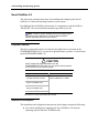
Setup Flow ................................................................................................................................... 2-2
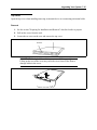
Selecting a Site............................................................................................................................. 2-3
Installation ............................................................................................................................... 2-3
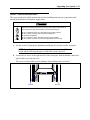
Rack Installation ...................................................................................................................... 2-3
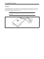
Unpacking the System ................................................................................................................. 2-5
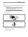
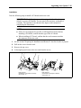
Assembling the Rack-mount System ........................................................................................... 2-6
Restricted Access Location...................................................................................................... 2-7
ESD Precaution ....................................................................................................................... 2-7
Checking Components............................................................................................................. 2-7
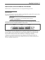
Required Tools......................................................................................................................... 2-7
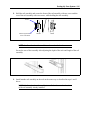
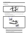
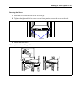
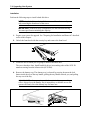
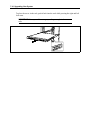
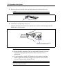
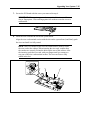
Installation Procedure for NEC Rack or Vendor’s Rack.......................................................... 2-8
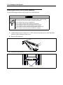
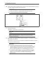
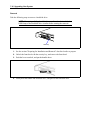
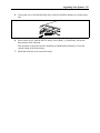
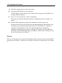
Removing the Server from the Rack Assembly..................................................................... 2-14
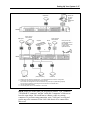
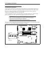
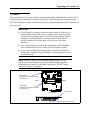
Connecting Peripheral Devices .................................................................................................. 2-16
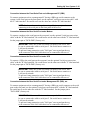
Connection to Serial Ports ..................................................................................................... 2-18
Connecting the Power Cord ....................................................................................................... 2-21
Turning On the Server................................................................................................................ 2-23
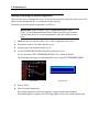
Installing the Operating System ................................................................................................. 2-25
Installing Utilities....................................................................................................................... 2-25
Making Backup Copies of System Information ......................................................................... 2-26
Chapter 3 Configuring Your System .............................................................................. 3-1
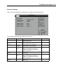
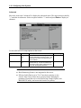
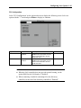
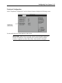
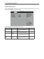
System BIOS ~ SETUP ~ ............................................................................................................ 3-1
Starting SETUP Utility............................................................................................................ 3-2
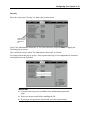
Description on On-Screen Items and Key Usage .................................................................... 3-3
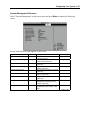
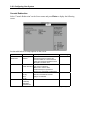
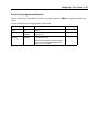
Configuration Examples .......................................................................................................... 3-4
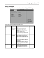
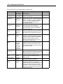
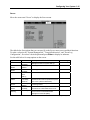
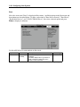
Menu and Parameter Descriptions........................................................................................... 3-9
SCSI BIOS ~ SCSISelect ~........................................................................................................ 3-31
Using SCSISelect Utility ....................................................................................................... 3-31
Configuring SCSI Controller on System Board .................................................................... 3-31
Configuring SCSI Controller on Optional Board .................................................................. 3-40
Configuring system Board Jumpers ........................................................................................... 3-41
Chapter 4 Installing the Operating System ................................................................... 4-1
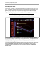
About Express Setup.................................................................................................................... 4-2
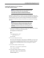
Microsoft Windows 2000............................................................................................................. 4-4
Installation Notice.................................................................................................................... 4-4
Setup Flow............................................................................................................................... 4-8
Installing and Configuring Device Drivers............................................................................ 4-13
Setup for Problem Resolution................................................................................................ 4-16
Installing Maintenance Utilities............................................................................................. 4-19
Updating the System - Applying Service Pack - ................................................................... 4-20
Making Backup Copies of System Information..................................................................... 4-20
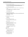
Microsoft Windows NT 4.0 ....................................................................................................... 4-21
Installation Notice.................................................................................................................. 4-21
Setup Flow............................................................................................................................. 4-24
Installing Windows NT 4.0.................................................................................................... 4-25
v
Installing and Setting Device Drivers.....................................................................................4-29
Setup for Problem Resolution.................................................................................................4-31
Installing Maintenance Utilities..............................................................................................4-36
Updating the System - Applying Service Pack - ....................................................................4-36
Making Backup Copies of System Information .....................................................................4-37
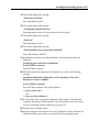
Novell NetWare 5.0 ....................................................................................................................4-38
Required Diskettes..................................................................................................................4-38
Installation Assumption..........................................................................................................4-38
Preparation .............................................................................................................................4-39
Installing the Novell NetWare v5.0 Network Operating System............................................4-43
Restarting the Server ..............................................................................................................4-45
Backing Up the Server............................................................................................................4-45
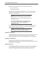
SCO OpenServer 5.0.6................................................................................................................4-46
Required Diskettes..................................................................................................................4-46
Preparation .............................................................................................................................4-47
Installing Optional Hardware .................................................................................................4-48
Installing and Configuring System Software..........................................................................4-49
Chapter 5 Maintenance ................................................................................................... 5-1
Making Backup Copies.................................................................................................................5-1
Cleaning........................................................................................................................................5-2
Cleaning the Server ..................................................................................................................5-3
Cleaning the Interior.................................................................................................................5-4
Cleaning the Keyboard/Mouse .................................................................................................5-5
Cleaning CD-ROM...................................................................................................................5-6
System Diagnostics.......................................................................................................................5-7
Test Items .................................................................................................................................5-7
Starting and Ending the System Diagnostics............................................................................5-8
Relocating/Storing the Server .....................................................................................................5-10
Chapter 6 Troubleshooting ............................................................................................. 6-1
System Viewers.............................................................................................................................6-2
Lamps ...........................................................................................................................................6-3
Error Messages .............................................................................................................................6-4
Error Messages after Power-on ................................................................................................6-4
POST Error Messages ..............................................................................................................6-5
Beep Codes.............................................................................................................................6-10
Solving Problems........................................................................................................................6-11
Problems with the Server........................................................................................................6-11
Problems with EXPRESSBUILDER......................................................................................6-20
Problems with Express Setup .................................................................................................6-21
Error Message during Disk Array Configuration ...................................................................6-26
Problems with Master Control Menu .....................................................................................6-26
Problems with Configuration Diskette Creator ......................................................................6-27
Collecting Event Log ..................................................................................................................6-28
Windows 2000........................................................................................................................6-28
Windows NT 4.0 ....................................................................................................................6-29
Collect Configuration Information..............................................................................................6-30
Windows 2000........................................................................................................................6-30
Windows NT 4.0 ....................................................................................................................6-30
Collecting Dr. Watson Diagnostic Information...........................................................................6-31
Memory Dump............................................................................................................................6-31
Preparing for Memory Dumping.................................................................................................6-31
Saving the Dump File.............................................................................................................6-32
Backup IPMI Information ......................................................................................................6-33
vi
Recovery for Windows 2000/Windows NT System .................................................................. 6-34
Off-Line Maintenance Utility .................................................................................................... 6-39
Starting the Off-line Maintenance Utility .............................................................................. 6-40
Features of Off-line Maintenance Utility............................................................................... 6-41
Resetting the Server ................................................................................................................... 6-42
Forced Shutdown ....................................................................................................................... 6-42
Chapter 7 Upgrading Your Server .................................................................................. 7-1
Safety Notes ................................................................................................................................. 7-2
Anti-static Measures .................................................................................................................... 7-3
Preparing Your System for Upgrade ............................................................................................ 7-4
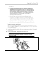
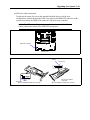
Device Installation or Removal Procedure .................................................................................. 7-5
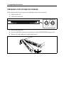
Hard Disk Drive....................................................................................................................... 7-5
Server ~ Pull-out from the Rack ~......................................................................................... 7-13
Top Cover .............................................................................................................................. 7-15
DIMM.................................................................................................................................... 7-17
Processor (CPU) .................................................................................................................... 7-22
PCI Board .............................................................................................................................. 7-31
Disk Array Controller Board ................................................................................................. 7-37
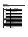
Appendix A Specifications .............................................................................................A-1
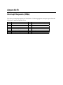
Appendix B Interrupt Requests (IRQs) ......................................................................... B-1
Appendix C Installing and Configuring Windows 2000 and Windows NT 4.0 .......... C-1
Windows 2000 .............................................................................................................................C-1
Device Drivers.........................................................................................................................C-1
Installation Assumption...........................................................................................................C-2
Preparation...............................................................................................................................C-3
Installing Microsoft Windows® 2000 Operating System.........................................................C-4
Installing LAN Adapters.........................................................................................................C-5
Driver Installation for the ATI RAGE XL Display Adapter....................................................C-5
Windows NT 4.0 ..........................................................................................................................C-6
Device Drivers.........................................................................................................................C-6
Configuring RAID...................................................................................................................C-7
Installing Microsoft Windows® NT 4.0 Operating System......................................................C-7
Installing LAN Adapter Drivers .............................................................................................C-8
Driver Installation for the ATI RAGE XL Display Adapter....................................................C-9
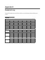
Appendix D Equipment Log........................................................................................... D-1
Hardware .................................................................................................................................D-1
Software...................................................................................................................................D-3
Using This Guide iii
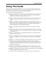
Using This Guide
Welcome to the NEC Express5800/120Rb-1 server User’s Guide. This User's Guide provides a
quick reference to information about your server system. Its goal is to familiarize you with your
system and the tasks necessary for system configuring and upgrading.
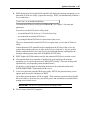
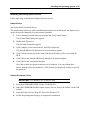
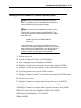
This guide contains the following information:
!
Chapter 1, “System Overview” provides all the information necessary to use the server,
including a description your system’s major system components. See this chapter to
familiarize yourself with your system and how to use it.
!
Chapter 2, “Setting Up Your System” tells you how to select a site, unpack the system,
assemble the rack-mount subsystem, make cable connections, and power on your
system.
!
Chapter 3, “Configuring Your System” tells you how to configure the system and
provides instructions for running the BIOS Setup Utility and the Adaptec Configuration
Utility, which is used to configure SCSI devices in your system. This chapter also
provides information on system board jumper settings.
!
Chapter 4, "Installing the Operating System" describes how to install the operating
system.
!
Chapter 5. "Maintenance" provides you with all the information necessary to maintain
successful operation of the server. This chapter also includes a description on relocating
and storing the server.
!
Chapter 6, “Troubleshooting” contains helpful information for solving problems that
might occur with your system.
!
Chapter 7, “Upgrading Your System” provides you with instructions for upgrading your
system with an additional processor, optional memory, options cards, and peripheral
devices.
!
Appendix A, “Technical Specifications” provides specifications for your server system.
!
Appendix B, “Interrupt Request/PCI IRQ Device/I/O Port Address Assignments"
provides the Interrupt Requests (IRQs), PCI IRQ device, and I/O port addresses that are
assigned by the factory for this system. These values can be used for reference when
installing an optional device.
!
Appendix C, “Installing Windows 2000/Windows NT 4.0" describes how to install
Microsoft Windows 2000 and Microsoft Windows NT 4.0 without using Express Setup.
!
Appendix D, “Equipment Log" provides a table for documenting your system configuration
and future updates you may make to your system.
!
“Glossary” defines the standard acronyms and technical terms used in this manual.
iv Using This Guide
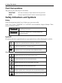
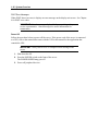
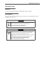
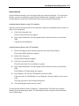
Text Conventions
This guide uses the following text conventions.
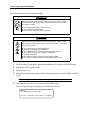
IMPORTANT:
Items that are mandatory or require attention when using the server
NOTE:
Notes give important information about the material being described.
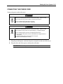
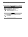
Safety Indications and Symbols
Safety
Follow the instructions in this User’s Guide to use your server safely.
In this User’s Guide a "WARNING" or "CAUTION" is used to indicate a degree of danger. These
terms are defined as follows:
WARNING
Warnings alert you to situations that could result in serious
personal injury or loss of life.
CAUTION
Indicates the presence of a hazard that may cause minor
personal injury, including burns, or property damage if the
instruction is ignored.
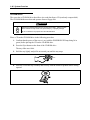
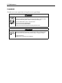
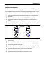
Symbols
Precautions and notices against hazards are represented with one of the following three symbols:
This symbol indicates the presence of a hazard if the instruction is ignored.
An image in the symbol illustrates the hazard type. (Attention)
This symbol indicates prohibited actions. An image in the symbol illustrates
a particular prohibited action. (Prohibited Action)
This symbol indicates mandatory actions. An image in the symbol illustrates
a mandatory action to avoid a particular hazard. (Mandatory Action)
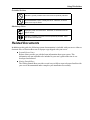
Attentions
Indicates that improper use may cause an electric shock.
Indicates that improper use may cause personal injury.
Indicates that improper use may cause fingers to be caught.
Indicates that improper use may cause fumes or fire.
Indicates a general notice or warning that cannot be specifically identified.
Indicates that improper use may cause loss of eyesight due to laser beam.
Using This Guide v
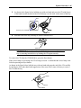
Prohibited Actions
Indicates a general prohibited action that cannot be specifically identified.
Do not disassemble, repair, or modify the server. Otherwise, an electric
shock or fire may be caused.
Mandatory Action
Unplug the power cord of the server. Otherwise, an electric shock or fire
may be caused.
Indicates a mandatory action that cannot be specifically identified. Make
sure to follow the instruction.
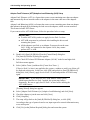
Related Documents
In addition to this guide, the following system documentation is included with your server either as
electronic files on EXPRESSBUILDER or as paper copy shipped with your server.
!
System Release Notes
Release Notes provide you with the latest information about your system. This
information was not available to be included in your user's guide at the time it was
developed and released.
!
Getting Started Sheet
The Getting Started Sheet provides several easy-to-follow steps to become familiar with
your server documentation and to complete your installation successfully.
vi Using This Guide
Safety Notices
!
!
Caution: To reduce the risk of electric shock which could cause personal injury, follow
all safety notices. The symbols shown are used in your documentation and on your
equipment to indicate safety hazards.
!
Warning: Lithium batteries can be dangerous. Improper handling of lithium batteries
may result in an explosion. Dispose of lithium batteries as required by local ordinance or
as normal waste if no local ordinance exists.
!
Warning: The detachable power supply cord is intended to serve as the disconnect
device.
!
Warning: This equipment has a 3-wire, grounded power cord. To prevent electrical
hazards, do not remove or defeat the ground prong on the power cord. Replace the
power cord if it gets damaged. Contact your dealer for an exact replacement.
!
Warning: The DC push-button on/off switch on the front panel does not turn off the
system AC power. Also, +5vdc is present on the system board whenever the AC power
cord is connected between the system and an AC outlet. Before doing the procedures in
this manual, make sure that your system is powered off and unplug the AC power cord
from the back of the chassis. Failure to disconnect power before opening your system
can result in personal injury and equipment damage.
In the U.S.A. and Canada, the power cord must be a UL-listed detachable power cord (in
Canada, CSA-certified), type ST or SJT, 16 AWG, 3-conductor, provided with a molded-on
NEMA type 5-15 P plug cap at one end and a molded-on cord connector body at the other
end. The cord length must not exceed 9 feet (2.7 meters).
Outside the U.S.A. and Canada, the plug must be rated for 250 VAC, 10 amp minimum,
and must display an international agency approval marking. The cord must be suitable for
use in the end-user country. Consult your dealer or the local electrical authorities if you are
unsure of the type of power cord to use in your country. The voltage change occurs via a
switch in the power supply.
!
Warning: Under no circumstances should the user attempt to disassemble the power
supply. The power supply has no user-replaceable parts. Inside the power supply are
hazardous voltages that can cause serious personal injury. A defective power supply
must be returned to your dealer.
Using This Guide vii
Safety Notices for Users Outside of the U.S.A. and Canada
!
PELV (Protected Extra-Low Voltage) Integrity: To ensure the extra-low voltage
integrity of the equipment, connect only equipment with mains-protected electricallycompatible circuits to the external ports.
!
Remote Earths: To prevent electrical shock, connect all local (individual office)
computers and computer support equipment to the same electrical circuit of the building
wiring. If you are unsure, check the building wiring to avoid remote earth conditions.
!
Earth Bonding: For safe operation, only connect the equipment to a building supply
that is in accordance with current wiring regulations in your country. In the U.K., those
regulations are the IEE.
viii Using This Guide
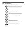
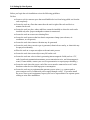
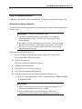
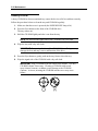
Care and Handling
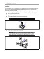
Use the following guidelines to properly handle and care for your system.
Protect the system from extremely low or high temperatures. Let
the system warm (or cool) to room temperature before using it.
Keep the system away from magnetic forces.
Keep the system dry. Do not wash the system with a wet cloth or
pour fluid into it.
Protect the system from being bumped or dropped.
Check the system for condensation. If condensation exists, allow it
to evaporate before powering on the system.
Keep the system away from dust, sand, and dirt.
Chapter 1
System Overview
This chapter provides information that you should familiarize yourself with before using the
server. It includes names and functions of the components and features of the server.
1-2 System Overview
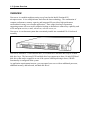
OVERVIEW
Your server is a modular multiprocessing server based on the Intel Pentium® III
microprocessors. It is a solid performer and offers the latest technology. The combination of
compute performance, memory capacity, and integrated I/O provides a high performance
environment for many server market applications. These range from large corporations
supporting remote offices to small companies looking to obtain basic connectivity capability such
as file and print services, e-mail, web access, web site server, etc.
Your server is a rack-mount system that conveniently installs into a standard EIA 19-inch rack
assembly.
Your server includes a 3.5-inch diskette drive, a CD-ROM drive and three hot-swap SCSI hard
disk drive bays. The hot-swap SCSI hard disk drive bays support up to three 1.0-inch SCSI hard
disk drives that can be swapped in or out of the system without powering it down, if RAID
functionality is configured in the system.
As application requirements increase, you can expand your server with an additional processor,
additional memory, add-in boards, and hard disk drives.
System Overview 1-3
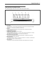
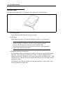
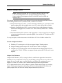
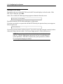
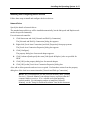
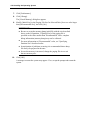
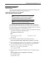
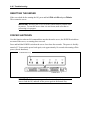
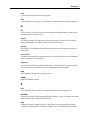
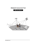
Front View with Front Bezel Closed
The following figure shows the location of the front system features.
3
1
1
2
3
4
5
6
7
4
5
6-1
6-2
7
2
Front bezel
The front bezel is a cover protecting and providing security for the front controls and devices
in the server. A security key is provided to lock the cover.
Keylock
Insert the security key into the key slot of the keylock when unlocking the front bezel.
POWER/SLEEP lamp (green)
This lamp turns green when the power is turned on.
STATUS lamp (green/amber)
This lamp indicates the server status. The lamp is green during normal operation. The lamp
turns amber color or flashes when the server enters an abnormal state.
DISK ACCESS lamp (green/amber)
This lamp is green during access to the internal hard disks. The lamp turns amber color
when one of the internal hard disks fails.
ACT lamp (green)
This lamp is on while the system is connected to the network. Icon number "1" indicates LAN
port 1, and Icon number "2" indicates LAN port 2.
UID lamp (blue)
This lamp goes on when the UID switch is pressed or when software issues a command.
1-4 System Overview
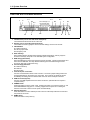
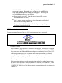
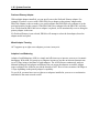
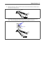
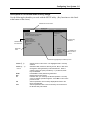
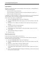
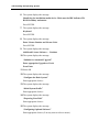
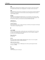
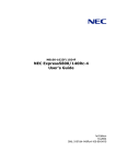
Front View with Front Bezel Removed
1
3-1
2
3-2
4-1
1
2
3
4
5
6
7
8
9
10
11
5
6-1
3-3
See 3 through 7 on
the previous page.
4-2
6-3
6-2
4-3
10
7
8
9
11
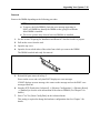
Thumbscrews (one on each side of the front panel)
The thumbscrews secure the server to the rack.
Handles (one on each side of the front panel)
The handles are used to grasp the server unit when sliding it in and out of the rack.
CD-ROM drive
3-1 Disk access lamp
3-2 CD tray eject button
3-3 Emergency hole
Hard disk bays
Each number following the bold-faced number indicates the SCSI ID. Dummy trays are
mounted in the bays, except 4-1 in the standard system configuration.
DISK lamp (green/amber)
Each hard disk lamp is green when the drive is being accessed. The lamp turns amber color
when the hard disk fails. The lamp flashes between green and amber during the build
process (in disk array configuration only).
3.5-inch floppy disk drive
6-1 Disk access lamp
6-2 Disk slot
6-3 Eject button
Front serial port 2 connector
Connect a serial interface device to this connector. The server jumper setting needs to be
changed depending on the device to be connected. This connector is capped to prevent
accidentally connecting a RJ-45 network cable connector to this serial port connector.
USB connectors (2 ports)
Connect only USB compliant devices to these connectors. (Windows NT 4.0 requires a
compliant driver.)
POWER switch
Press this switch to turn the power on/off. Pressing the switch once turns the power on, and
the POWER/SLEEP lamp goes on. Pressing it again turns the power off. Pressing the
switch for 4 seconds or more turns the power off automatically.
UID (unit ID) switch
Press this switch to turn the UID lamps on/off. There is a UID lamp located on the front and
rear panels of the server.
DUMP switch
Press this switch to dump memory.
System Overview 1-5
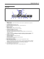
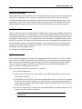
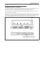
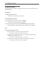
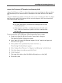
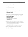
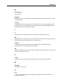
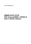
Rear View
7
6
5-2
2
5-1
10
7
1
1
2
3
4
5
6
7
8
9
10
3
4
8
9
1
11
12
13
14
USB connector
Connect a device compliant USB interface to this connector. (Windows NT 4.0 requires a
compliant driver.)
Low-profile PCI board extension slot
Mount a low-profile PCI board into this slot. The slot number is 1C.
Monitor connector
Connect a monitor display unit to this connector.
SCSI connector
Connect an external SCSI device to this connector.
100BASE-TX/10BASE-T connectors
Connect LAN network systems to these connectors.
The number "1" following bold-faced number 5 indicates LAN port 1, and the number "2"
indicates LAN port 2.
To remove a connector in LAN port 1 use a flat-tip screwdriver to push the locking tab on the
connector. Use care not to damage the LAN port or any other ports with screwdriver.
LINK/ACT lamp (green)
This lamp indicates access status of the LAN.
Speed lamp (amber)
This lamp indicates the transmission speed of the LAN.
Mouse/keyboard connector
Connect the mouse and keyboard to the connector using the PS2 "Y" cable.
Rear serial port 2 connector
Connect a serial interface device to this connector. The server setting needs to be changed
depending on the device to be connected. This connector is capped to prevent accidentally
connecting a RJ-45 network cable connector to this serial port connector.
Full-height PCI board extension slots
Mount a full-height PCI board in this slot. The slot number is 1B.
1-6 System Overview
11
12
13
14
STATUS lamp (green/amber) (on the real panel)
This lamp indicates the server status. The lamp is green color during normal operation. The
lamp turns amber color or flashes when the server enters an abnormal state.
POST lamps
The POST lamps are when POST is running and checking the system.
UID lamp (blue)
This lamp goes on when the UID switch is pressed or when a software command is issued.
AC inlet
Connect the power cord to this socket.
The "100BASE-TX/10BASE-T connector" (Feature 5
above) and the "serial port 2 connector" (Feature 9 above) are the same
size and shape. Be careful when connecting a cable to either one of these
connectors in order to prevent accidentally connecting a RJ-45 network
cable connector to a serial port connector or vice versa.
IMPORTANT:
System Overview 1-7
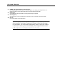
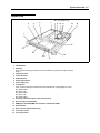
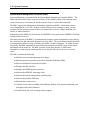
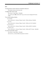
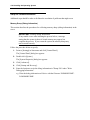
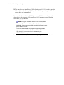
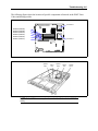
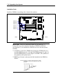
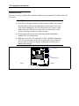
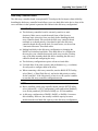
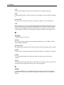
Internal View
8-1 to 8-5 (right to left)
4
5
6
7
9 10
11
12
1
14
2-1
2-2
15
2-3
3
1
CD-ROM drive
2
3
Disk bays
(Each number following the bold-faced number indicates the placement order of the disk
drives.)
Floppy disk drive
4
Front LED board
5
SCSI backplane
6
Power jumper board
7
Power supply unit
8
Cooling fans
(Each number following the bold-faced number indicates the corresponding fan name.)
8-1 System FAN 3
8-2 CPU 2 FAN
8-3 System FAN 2
8-4 CPU 1 FAN
8-5 System FAN 1
Processor (mounted under the CPU and heat sink)
9
10
Riser card (full-height boards)
11
DIMM (Two standard DIMMs are mounted in slots #1A and #1B.)
12
System board
13
Riser card (low-profile boards only)
14
Cover open sensor
15
Front panel board
13
1-8 System Overview
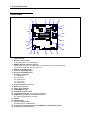
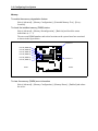
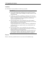
System Board
1
2
3
4
5
6
7-1
7-2
19
7-3
7-4
7-5
18
8
17
16
9
15
1
2
3
4
5
6
7
8
9
10
11
12
13
14
15
16
17
18
19
14
13
12
11
10
ICMB connector
PCI riser card connector
(Low-profile boards only. 66 MHz/64-bit)
DIMM sockets (for interleave memory)
(Starting from the top of the sockets that are shown above, the sockets are sequentially
numbered #3B, #2B, #1B, #3A, #2A, and #1A.)
USB connector(front panel)
Processor #1 (CPU#1) socket
Processor #2 (CPU#2) socket
Cooling fan connectors
7-1 System FAN 3
7-2 CPU 2 FAN
7-3 System FAN 2
7-4 CPU 1 FAN
7-5 System FAN 1
Peripheral interface connector
Main power connector
Power signal connector
SCSI IPMB connector
Configuration jumper switch
Internal SCSI connector (for internal hard disk drives)
SCSI/disk array controller access lamp connector
(For optional SCSI/disk array controller.)
Speaker
Lithium battery
PCI riser card connector
(Full-height boards. 66 MHz/64-bit)
Jumper pin for selecting a serial port DCD/DSR pin-out (J6A2 jumper block)
Connectors for external device
System Overview 1-9
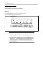
STATUS INDICATORS
This section describes the server status indicators.
POWER Lamp (
)
The POWER lamp is lit (green) while the server power is on. It is off when no power is being
supplied to the server.
NOTE:
This server does not support power saving mode.
STATUS Lamp (
)
The STATUS lamp is lit (green) while the server is operating normally. (There is a STATUS
lamp located on both the front and rear panels of the server.) If the STATUS lamp is off or turns
amber color and flashes, it indicates that the server is in an abnormal state.
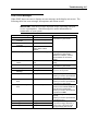
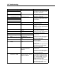
The table below lists and describes the STATUS lamp indications and any actions to be taken.
NOTES:
!
If ESMPRO or the offline maintenance utility is installed, you can
determine the cause of a failure by referring to the error log.
!
The system can be restarted automatically. However, if the automatic
restart cannot be performed for any reason, then the system must be
shutdown manually by turning the power off and back on.
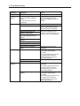
1-10 System Overview
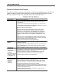
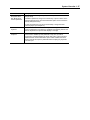
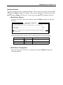
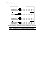
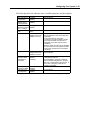
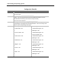
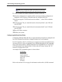
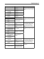
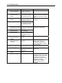
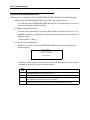
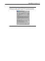
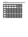
STATUS lamp
indication
On (green)
Flashing
(green)
Description
Action
The server is operating normally.
–
Identify the device in degraded state
by using the BIOS setup utility
"SETUP," and replace it as soon as
possible.
• The server is operating with the
memory or CPU in degraded
state.
• A 1-bit memory error occurs
frequently.
Off
On (amber)
Flashing
(amber)
Power is off.
POST is in progress.
CPU error occurred.
CPU temperature alarm was
detected. (Thermal-Trip)
A timeout occurred when the time
set for the watchdog timer was
reached.
An uncorrectable memory error was
detected.
PCI system error occurred.
PCI parity error occurred.
CPU bus error occurred.
A memory dump request was
issued.
A temperature alarm was detected.
A voltage alarm was detected.
All the power supply units failed.
A fan alarm was detected.
A temperature warning was
detected.
–
Wait while POST is checking the
system. The STATUS lamp turns
green when POST is completed.
Turn the power off and on. If the
POST screen displays an error
message, record the message, and
contact your service representative.
Wait until the memory dump is
completed.
Check if the internal fans are clean
and if the fan units are firmly
connected.
If the STATUS lamp indication does
not change when the fans are
operating correctly, contact your
service representative.
Contact your service representative.
Check if the fan units are firmly
connected.
If the STATUS lamp indication does
not change when the fans are
operating correctly, contact your
service representative.
Check if the internal fans are clean
and if the fan units are firmly
connected.
If the STATUS lamp indication does
not change when the fans are
operating correctly, contact your
service representative.
System Overview 1-11
DISK ACCESS Lamp ( )
The DISK ACCESS lamp indicates the status of the hard disk mounted in the 3.5-inch device
bay.
The lamp turns green each time access is made to the hard disk.
When the DISK ACCESS lamp turns amber color, it indicates that a hard disk failure has
occurred. Check the hard disk lamp for the status of the failing hard disk.
When the DISK ACCESS lamp flashes between green and amber or if the lamp turns amber and
flashes, it indicates that rebuild (reconstruction) processing is being performed for a hard disk
connected to the internal disk array controller.
If a hard disk in the server is connected to the internal disk
array controller, the access lamp signal cable (provided with the server)
must be connected from the disk array controller to the system board.
IMPORTANT:
ACT Lamp (
)
The ACT lamp is a green color while the server is connected to the LAN. The lamp flashes while
the server is accessed via the LAN (during transmission/reception of packets). The number next
to the icon indicates the network port number on the rear panel of the server.
Disk Access Lamp
The disk access lamp on the floppy disk drive or CD-ROM drive is lit while the drive is accessed.
1-12 System Overview
Hard Disk Lamp
The disk lamp mounted in the 3.5-inch device bay indicates the following status:
Lamp
!
Flashing (green)
Lamp indicates that the hard disk is being accessed.
!
Lit (amber)
Lamp indicates a failure of a hard disk mounted in a disk array configuration.
Even if one of the hard disks fails in disk array configuration
(RAID1, RAID5, or RAID0+1), the server can continue operation.
However, the disk must be replaced as soon as possible, and
reconstruction (rebuild) processing must be performed. (The failing disk
can be replaced in hot swap mode.)
NOTE:
!
Flashing between green and amber
The lamp indicates that reconstruction (rebuild) processing is being performed for the
hard disk. (This flashing does not indicate a failure.) When a failing hard disk is
replaced in disk array configuration, the system automatically rebuilds the data. (Autorebuild function) The lamp switches back and forth between green and amber during
rebuild processing.
The lamp goes off when the rebuild processing has terminated. It turns amber color
when the rebuild processing fails.
System Overview 1-13
If the server is turned off during rebuild processing, the
processing is stopped. Restart the server, mount the new hard disk in hot
swap mode, and then perform rebuild processing again. When using the
auto-rebuild function observe the following:
IMPORTANT:
!
Do not turn the power off. (Once the power is turned off, the autobuild function does not start.)
!
Let 90 seconds or more pass between when dismounting a failing hard
disk and when mounting the new one.
!
Do not replace a failing hard disk while rebuild processing is being
performed for another hard disk.
LAN Connector Lamps
There are two lamps for each of the two LAN ports (connectors) on the rear panel.
LINK/ACT lamps
!
Speed lamps
LINK/ACT lamps
Each LINK/ACT lamp indicates the status of its network port. While power is supplied
to the server and HUB and the connection is correct (LINK), the lamp is lit (green). The
lamp turns green and flashes while the network port is transmitting/receiving data (ACT).
If the lamp does not light in the LINK state, check if the network cable is connected
correctly. If the lamp still does not light when everything looks normal, the network
(LAN) controller may be faulty. In this case, contact your service representative.
!
Speed lamps
Each Speed lamp indicates that the communication mode of the standard network port of
the server is activated with the network interface of 100BASE-TX or 10BASE-T. When
the lamp is lit (amber), it indicates that the communication mode is activated with
100BASE-TX. When it is off, it indicates that the communication mode is activated with
10BASE-T.
1-14 System Overview
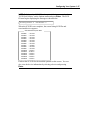
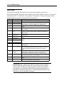
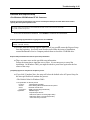
STANDARD FEATURES
High performance
! Intel Pentium III Processor
(1GHz/1.26GHz-S)
! High-speed 100BASE-TX/10BASE-T
interface (100Mbps/10Mbps supported)
! High-speed disk access
(Ultra160 SCSI x 2)
! High-speed memory access (133MHz,
ECC, registered, PC/133 compliant, 72bit, 68-pin, 3.3V)
Expandability
! Two PCI add-in card slots (full-length,
full-height 64-bit/66-MHz and low-profile
64-bit/66-MHz)
! Up to 6 GB of memory
! Three hot-swap SCSI hard disk drive
bays
! Up to two multi-processors are available
for upgrade.
! USB interface (USB-support driver is
required.)
! Two network ports
High-reliability
! Memory monitoring feature (1-bit error
correction/ 2-bit error detection)
! CPU/memory degradation feature (logical
isolation of a failed device)
! Bus parity error detection
! Temperature detection
! Error notification
! Internal fan monitoring feature
! Internal voltage monitoring feature
! Auto-rebuild feature (optional, hotswappable)
! BIOS password feature
! Mechanical security lock
Many Available Features
! Graphic accelerator "RAGE XL" support
! El Torito Bootable CD-ROM (no
emulation mode) format support
! POWER switch mask
! Software power-off
! Remote power-on feature
! AC-LINK feature
! Baseboard Management Controller
(BMC)
! Consoleless feature
Management Utilities
! ESMPRO
! Management Workstation Application
(MWA)
Maintenance Features
! Off-line Maintenance Utility
! Memory dump feature using the DUMP
switch
Self-diagnosis
! Power On Self-Test (POST)
! Test and Diagnosis (T&D)
Easy and Fine Setup
! EXPRESSBUILDER (system setup
utility)
! Configuration Parameter Diskette Creator
! SETUP (BIOS setup utility)
! SCSISelect (SCSI device utility)
System Overview 1-15
Power Supply
The power supply is rated for 250 watts of power.
The power subsystem supports the remote management features, including remote enable that
permits power to be activated from a variety of sources.
Peripheral Bays
Your server supports a variety of standard PC AT-compatible peripheral devices. The chassis
includes the following peripheral bays:
!
A 3.5-inch front panel bay for mounting the standard 3.5-inch diskette drive (supports
720 KB and 1.44 MB diskette media)
!
A standard CD-ROM drive bay
!
Three hot-swap SCSI hard disk drive bays for mounting hard disk drives installed in
easily removable drive carriers.
NOTE: The hot-swap SCSI hard disk drive bays contain a hot-swap back
plane that require an 80-pin single connector attachment (SCA) connector
on the drives that you install.
System Cooling
The chassis includes a non-hot-swappable fan module with five fans for cooling the processor(s),
hard drives, and PCI cards. The fan system is located in the middle of the chassis to pull cooling
air through the chassis. The power supply contains two built-in fans for cooling.
1-16 System Overview
SAF-TE LOGIC
NOTE: SAF-TE Logic is in systems that include the hot-swap SCSI disk
drive cage. SAF-TE Logic is not available in systems that include the
standard SCSI disk drive cage.
The SCSI backplane includes SAF-TE (SCSI Accessed Fault Tolerant Enclosure) logic that
provides an interface to the disk subsystem that supports status signals, hot swapping drives, and
enclosure monitoring.
The transport mechanism for the standardized alert detection and status reporting is the SCSI bus.
Disk drives, power supplies, cooling fans, and temperature are continually monitored and the
conditions then reported over the SCSI bus to the system. When used with RAID management
software the user can be alerted of impending or imminent disk conditions requiring attention.
This allows the user to react to conditions that could normally go unnoticed until data loss.
SYSTEM BOARD FEATURES
The following subsections describe the major components of the system board. See "System
Board" earlier in this chapter.
Processor
The system board accommodates one or two Intel Pentium III processors with 512k cache in the
FC-PGA2 package. This processor uses the .13 micron technology and offers advanced
performance. The processor external interface operates at a maximum of 133 MHz.
Memory
The system board contains six 168-pin DIMM sockets each supporting 72-bit ECC (64-bit main
memory plus ECC) registered SDRAM DIMMs (PC-133 compatible). Memory is two-way
interleaved and partitioned in three banks. You may install a minimum of 256 MB (128MB × 2)
and as much as 6 GB.
The controller automatically detects, sizes, and initializes the memory array, depending on the
type, size, and speed of the installed DIMMs and reports memory size and allocation to the server
via configuration registers.
Use DIMMs that have been tested for compatibility with the server
board.
Contact your service representative or dealer for a current list of approved
memory modules.
NOTE:
System Overview 1-17
PCI Riser Slots
The server board has two PCI riser slots, each capable of supporting 64-bit/66-MHz PCI riser
cards.
PCI features:
!
Bus speed up to 66 MHz
!
32 bit memory addressing
!
5 V/3.3 V signaling environment
!
Burst transfers of up to 512 Mbps
!
8, 16, 32, or 64-bit data transfers
!
Plug and Play ready
!
Parity enabled
Video
The system board uses an ATI RAGE XL PCI graphics accelerator with 8 MB of video SDRAM
that supports all standard IBM VGA modes. The embedded SVGA video subsystem supports:
!
Pixel resolutions up to 1600 x 1200 under 2D and 1024 x 768 under 3D
!
CRT and LCD monitors up to 100 Hz vertical refresh rate
The server board supports disabling of the onboard video through the BIOS setup menu or when
a plug in video card is installed in any of the PCI slots.
SCSI Controller
The SCSI version of the server board includes an embedded Adaptec AIC-7899W controller
providing dual Ultra160 Low Voltage Differential (LVD) SCSI channels.
The SCSI bus is terminated on the server board with active terminators that cannot be disabled.
The onboard device must always be at one end of the bus. The device at the other end of the cable
must also be terminated. LVD devices generally do not have termination built-in and need to have
a termination source provided. Non-LVDs devices generally are terminated through a jumper or
resistor pack on the device itself.
1-18 System Overview
Network Controller
To ensure EMC product regulation compliance, the system must be
used with a shielded LAN cable.
NOTE:
The server board uses two Intel ® 82550PM Fast Ethernet Controllers and supports two 10BaseT/100Base-TX network subsystems.
The 82550 PM controller supports the following features:
!
32-bit PCI, CardBus master interface
!
Integrated IEEE 802.3 10Base-T and 100Base-TX compatible PHY
!
IEEE 820.3u auto-negotiation support
!
Chained memory structure similar to the 82559, 82558, 82557 and 82596
!
Full duplex support at both 10 Mbps and 100 Mbps operation
!
Low power +3.3 V device
!
IP checksum off-loading
On the system board, NIC 1 can be used as both a network interface and server management
interface.
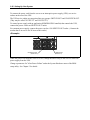
NIC Connector and Status LEDs
The 82550 controller drives LEDs on the network interface connector that indicate link/activity
on the LAN and 10- or 100-Mbps operation. The green LED indicates network connection when
lit and TX/RX activity when blinking. The yellow LED indicates 100-Mbps operation when lit.
System Overview 1-19
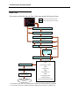
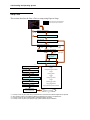
Network Teaming Features
Using both on-board NICs in a team does not allow the use of NIC
1 for server management access. To support both network teaming
features and server management features, a third NIC must be added and
teamed to NIC 2.
NOTE:
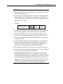
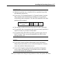
The network controller provides several options for increasing throughput and fault tolerance
when running Windows NT 4.0, Windows 2000 , NetWare 4.2 or newer:
!
Adapter Fault Tolerance (AFT) - provides automatic redundancy for your adapter. If the
primary adapter fails, the secondary takes over. AFT works with any hub or switch.
!
Adaptive Load Balancing (ALB) - creates a team of two to eight adapters to increase
transmission throughput. Also, includes AFT. Works with any 10Base-TX or 100BaseTX switch.
!
Fast EtherChannel (FEC) or Intel ® Link Aggregation - creates a team of up to 8 adapters
to increase transmission and reception throughput. Also includes AFT. Requires an FECenabled switch.
To set up an option, read the instructions in the Windows NT 4.0 or NetWare readme files.
General Configuration Notes
1.
Windows NT versions prior to 4.0 do not support Adapter Teaming options.
2.
Adapter Teaming options require NT 4.0 with Service Pack 4.0 or higher.
3.
In Windows NT, teaming options cannot be implemented on adapters that have been
configured for VLANs. NetWare can support teaming options and VLANs on the same
adapters.
Adapter Fault Tolerance
Adapter Fault Tolerance (AFT) is a simple, effective, and fail-safe approach to increase the
reliability of server connections. AFT gives you the ability to set up link recovery to the server
adapter in case of a cable, port, or network interface card failure. By assigning two server
adapters as a team, AFT enables you to maintain uninterrupted network performance.
AFT is implemented with two server adapters: a primary adapter and a backup, or secondary,
adapter. During normal operation, the backup will have transmit disabled. If the link to the
primary adapter fails, the link to the backup adapter automatically takes over.
1-20 System Overview
Preferred Primary Adapter
With multiple adapters installed, you can specify one as the Preferred Primary adapter. For
example if you have a server with a PRO/1000 server adapter as the primary adapter and a
PRO/100+ adapter as the secondary, you could configure the PRO/1000 server adapter to be the
preferred primary. In this scenario, if the PRO/1000 server adapter fails, the PRO/100+ will take
over. Then when the PRO/1000 server adapter is replaced, it will automatically revert to being the
primary adapter in the team.
If a Preferred Primary is not selected, PROSet will attempt to select the best adapter, based on
adapter model and speed.
Mixed Adapter Teaming
AFT supports up to eight server adapters per team, in any mix.
Adaptive Load Balancing
Adaptive Load Balancing (ALB) is a simple and efficient way to increase your server’s transmit
throughput. With ALB you group server adapters in teams to provide an increased transmit rate
(up to 8 Gbps) using a maximum of eight adapters. The ALB software continuously analyzes
transmit loading on each adapter and balances the rate across the adapters as needed. Adapter
teams configured for ALB also provide the benefits of AFT. Receive rates remain at 100 Mbps or
1 Gbps depending on the primary adapter’s capability.
To use ALB, you must have two to eight server adapters installed in your server or workstation
and linked to the same network switch.
System Overview 1-21
Keyboard and Mouse
The keyboard and mouse controller is PS/2-compatible. The server may be locked automatically
if there is no keyboard or mouse activity for a predefined length of time. Once the inactivity
(lockout) timer has expired, the keyboard and mouse do not respond until the previously stored
password is entered. The Y-cable (shipped with your system) can be used if both a PS/2 mouse
and keyboard are required at the same time. The keyboard and mouse are ordered separately.
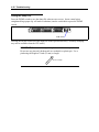
RJ-45 Serial Port
The rear RJ-45 serial port is a fully functional COM port that supports any standard serial device
and provides support for serial concentrators, which typically support RJ45 serial connectors. For
server applications that use a serial concentrator to access the server management features of the
baseboard, a standard 8-pin CAT-5 cable from the serial concentrator is plugged directly into the
rear RJ45 serial port. The 8 pins of the RJ45 connector can be configured to match either of two
pin-out standards used by serial port concentrators. To accommodate either standard, the J6A2
jumper block located directly behind the rear RJ45 serial port must be jumpered appropriately
according to which standard is desired.
See Chapter 3 for detail explanation.
ACPI
The system board supports the Advanced Configuration and Power Interface (ACPI) as defined
by the ACPI 1.0 and PC97 specifications. An ACPI aware operating system can put the system
into a state where the hard drives spin down, the system fans stop, and all processing is halted.
However, the power supply will still be on and the processors will still be dissipating some
power, so the power supply fans will still run.
The system board supports sleep states s0, s1, s4, and s5:
!
s0: Normal running state.
!
s1: Processor sleep state. No context will be lost in this state and the processor caches
will maintain coherency.
!
s4: Hibernate or Save to Disk: The memory and machine state are saved to disk. Pressing
the power button or other wakeup event will restore the system state from the disk and
resume normal operation. This assumes that no hardware changes have been made to the
system while it was off.
!
s5: Soft off: Only the RTC section of the CSB and the BMC are running in this state. No
context is saved by the OS or hardware.
IMPORTANT:
disconnected.
The system is off only when the AC power cord is
1-22 System Overview
System Board Management Controller (BMC)
Server management is concentrated in the System Board Management Controller (BMC). The
BMC and associated circuitry are powered from a 5Vdc standby voltage, which remains active
when system power is switched off, but the ac power source is still on and connected.
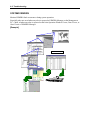
The BMC supports the Management Workstation Application (MWA), which allows remote
server management via a LAN, a modem, or direct connection to a manager system. Events
monitored by the manager system include over-temperature and over-voltage conditions, fan
failure, or chassis intrusion.
Information on the MWA may be found in the ESMPRO User's guide on the ESMPRO CD-ROM
included with your server.
One major function of the BMC is to autonomously monitor system management events, and log
their occurrence in the nonvolatile System Event Log (SEL). The events being monitored include
overtemperature and overvoltage conditions, fan failure, or chassis intrusion. To enable accurate
monitoring, the BMC maintains the nonvolatile Sensor Data Record (SDR), from which sensor
information can be retrieved. The BMC provides an ISA host interface to SDR sensor
information, so that software running on the server can poll and retrieve the server's current
status.
The BMC performs the following:
!
Monitors server board temperature and voltage
!
Monitors processor presence and controls Fault Resilient Boot (FRB)
!
Detects and indicates baseboard fan failure
!
Manages the SEL interface
!
Manages the SDR Repository interface
!
Monitors the SDR/SEL timestamp clock
!
Monitors the system management watchdog timer
!
Monitors the periodic SMI timer
!
Monitors the event receiver
!
Controls secure mode, including video blanking, diskette write-protect monitoring, and
front panel lock/unlock initiation
!
Controls Wake On LAN via Magic Packet support.
System Overview 1-23
DEGRADATION FEATURE
The degradation feature automatically isolates a failed DIMM or processor to assure continuous
operation of the server when the POST (Power On Self-Test, self-diagnosis program after power
on) detects such a DIMM or processor.
NOTE: The degradation feature is only available when at least two
DIMMs or processors are installed.
Failed DIMMs and processors may be identified on the screen that the POST displays, or with the
BIOS setup utility of the server, "SETUP." They may also be identified on the system that has the
ESMPRO installed.
REMOTE POWER-ON FEATURE (WAKE ON LAN)
The remote power-on function turns on the server through a network. It sends a special packet
from the management computer to a remote server to turn it on if the server is off-powered.
To enable this feature, you must select "Enabled" for "Wake On LAN" in the Wake On Event of
the System Hardware menu of the BIOS setup utility, "SETUP." (See Chapter 3.)
The remote power-on feature is not available in the following cases. Press the POWER switch
once to start the OS, and turn off the server in an appropriate procedure.
!
Abnormal previous system shut-down
!
No power supply to the server (due to turned-off breaker, disconnected power cord,
power blackout, etc.)
AC-LINK FEATURE
When the power cord of the server is connected to an uninterruptible power supply (UPS) unit,
the server supports the power linkage feature that enables control over the power supply from the
UPS to the server. The AC-LINK feature can be enabled or disabled with the System Hardware
menu of the BIOS setup utility, "SETUP." (See Chapter 3.)
1-24 System Overview
SYSTEM SECURITY
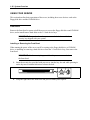
To help prevent unauthorized entry or use of the system, the system includes a full lockable front
bezel and Server Management software that monitors the front bezel intrusion switch.
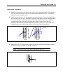
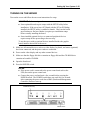
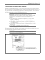
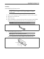
Security with Mechanical Locks and Monitoring
To unlock the bezel, insert the key in the lock and turn the lock counterclockwise until it stops
(about a quarter turn). The bezel is now unlocked and can be opened again.
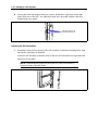
To lock the bezel, insert the key in the lock. Turn the lock clockwise until it stops (about a quarter
turn). The bezel is now locked and cannot be opened.
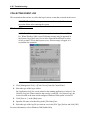
Software Locks via the BIOS Setup Utility
The BIOS Setup Utility provides a number of security features to prevent unauthorized or
accidental access to the system. Once the security measures are enabled, you can access the
system only after you enter the correct password(s). For example:
!
Enable the keyboard lockout timer so that the server requires a password to reactivate the
keyboard and mouse after a specified time out period – 1 to 120 minutes.
!
Set and enable a supervisor password.
!
Set and enable a user password.
!
Set secure mode to prevent keyboard or mouse input and to prevent use of the front panel
reset and power switches.
!
Activate a hot key combination to enter secure mode quickly.
!
Disable writing to the diskette drive when secure mode is set.
!
Disable access to the boot sector of the operating system hard disk drive.
System Overview 1-25
Using Passwords
You can set either the user password, the supervisor password, or both passwords. If only the user
password is set, you:
!
Must enter the user password to enter BIOS Setup.
!
Must enter the user password to boot the server if Password on Boot is enabled in either
the BIOS Setup.
!
Must enter the user password to exit secure mode.
If only the supervisor password is set, you:
!
Must enter the supervisor password to enter BIOS Setup.
!
Must enter the supervisor password to boot the server if Password on Boot is enabled in
either the BIOS Setup.
!
Must enter the supervisor password to exit secure mode.
If both passwords are set, you:
!
May enter the user password to enter BIOS Setup. However, you will not be able to
change many of the options.
!
Must enter the supervisor password if you want to enter BIOS Setup and have access to
all of the options.
!
May enter either password to boot the server if Password on Boot is enabled in either the
BIOS Setup.
!
May enter either password to exit secure mode.
Secure Mode
Configure and enable the secure boot mode by using the BIOS Setup. When secure mode is in
effect:
!
You can boot the server and the operating system will run, but you must enter the user
password to use the keyboard or mouse.
!
You cannot turn off system power or reset the server from the front panel switches.
Secure mode has no effect on functions enabled via remote server management or power control
via the watchdog timer.
Taking the server out of secure mode does not change the state of system power. That is, if you
press and release the power switch while secure mode is in effect, the system will not be powered
off when secure mode is later removed. However, if the front panel power switch remains
depressed when secure mode is removed, the server will be powered off.
1-26 System Overview
Summary of Software Security Features
The table below lists the software security features and describes what protection each offers. In
general, to enable or set the features listed here, you must run the BIOS Setup and go to the
Security Subsystem Group, menu. The table also refers to the Setup utility.
Software Security Features
Feature
Secure mode
Description
How to enter secure mode:
• Setting and enabling passwords automatically places the system in
secure mode.
• If you set a hot-key combination (through Setup), you can secure the
system simply by pressing the key combination. This means you do not
have to wait for the inactivity time-out period.
When the system is in secure mode:
The server can boot and run the operating system, but mouse and
keyboard input is not accepted until the user password is entered.
At boot time, if a CD is detected in the CD-ROM drive or a diskette in
drive A, the system prompts for a password. When the password is
entered, the server boots from CD or diskette and disables the secure
mode.
If there is no CD in the CD-ROM drive or diskette in drive A, the server
boots from drive C and automatically goes into secure mode. All enabled
secure mode features go into effect at boot time.
To leave secure mode: Enter the correct password(s).
Disable writing to
diskette
In secure mode, the server will not boot from or write to a diskette unless
a password is entered.
To write protect access to diskette whether the server is in secure mode
or not, use the Setup main menu, Floppy Options, and specify Floppy
Access as read only.
Set a time out
period so that
keyboard and
mouse input are not
accepted.
Also, screen can be
blanked, and writes
to diskette can be
inhibited
Control access to
using the BIOS
Setup: set
supervisor
password
Specify and enable an inactivity time out period of from 1 to 120 minutes.
If no keyboard or mouse action occurs for the specified period, attempted
keyboard and mouse input will not be accepted.
The monitor display will go blank, and the diskette drive will be write
protected (if these security features are enabled through Setup).
To resume activity: Enter the correct password(s).
To control access to setting or changing the system configuration, set a
supervisor password and enable it through Setup.
If both the supervisor and user passwords are enabled, either can be
used to boot the server or enable the keyboard and/or mouse, but only
the supervisor password will allow Setup to be changed.
To disable a password, change it to a blank entry or press CTRL-D in the
Change Password menu of the Supervisor Password Option menu found
in the Security Subsystem Group.
To clear the password if you cannot access Setup, change the Clear
Password jumper (see Chapter 3).
System Overview 1-27
Feature
Control access to
the system other
than BIOS Setup:
set user password
Description
To control access to using the system, set a user password and enable it
through Setup.
To disable a password, change it to a blank entry or press CTRL-D in the
Change Password menu of the User Password Option menu found in the
Security Subsystem Group.
To clear the password if you cannot access Setup, change the Clear
Password jumper (see Chapter 3).
Boot without
keyboard
The system can boot with or without a keyboard. During POST, before the
system completes the boot sequence, the BIOS automatically detects and
tests the keyboard if it is present and displays a message.
Specify the boot
sequence
The sequence that you specify in setup will determine the boot order. If
secure mode is enabled (a user password is set), then you will be
prompted for a password before the server fully boots. If secure mode is
enabled and the “Secure Boot Mode” option is also enabled, the server
will fully boot but will require a password before accepting any keyboard
or mouse input.
1-28 System Overview
EXPRESSBUILDER
The CD-ROM that comes with the server contains a setup utility called "EXPRESSBUILDER."
When you first install the server or append features to the server, use the EXPRESSBUILDER to
set up your server.
Refer to the EXPRESSBUILDER User's Guide on the EXPRESSBUILDER CD for details.
IMPORTANT: The EXPRESSBUILDER is server specific and can only
be used on the server that it is provided with, otherwise it may cause
failures.
The major features of the EXPRESSBUILDER are:
!
Install the OS.
It installs an operating system.
!
Diagnose the system.
It diagnoses the server.
!
Create a support disk.
It copies utilities in the EXPRESSBUILDER CD-ROM onto a floppy disk to launch
them from the floppy disk.
!
Update the Windows System*
It updates several resources of Microsoft Windows 2000 or Windows NT.
!
Install utilities
It installs the management utilities of ESMPRO and MWA.
!
Read online documents*
It opens the online document files (".pdf" files).
* These functions are available under Windows system.
NOTE: Some of the features listed above can be used from the remote
computer via cross cable, modem, or LAN (non-console feature).
System Overview 1-29
ESMPRO
ESMPRO is server management software that runs on the OS. ESMPRO includes the ESMPRO
Manager for the server monitoring terminal and the ESMPRO Agent for the server.
NOTE: For details of the ESMPRO major functions (i.e., system
configuration and setups) see the ESMPRO User's Guide on the ESMPRO
CD.
Available functions of ESMPRO depend on the OS you install. Ask your
service representative for details.
OFF-LINE MAINTENANCE UTILITY
The Off-line Maintenance Utility is used for proactive maintenance and fault analysis of the
server.
Refer to the EXPRESSBUILDER User's Guide on the EXPRESSBUILDER CD for details.
SYSTEM DIAGNOSTIC UTILITY
The system diagnostic utility contained in the EXPRESSBUILDER is useful to prevent hardware
failures.
MANAGEMENT WORKSTATION APPLICATION
(MWA)
The Management Workstation Application (MWA) is an application program for remote
management of the server from a system management computer (a computer with the ESMPRO
Manager running) through a network.
Information on MWA may be found in the ESMPRO User's Guide on the ESMPRO CD.
1-30 System Overview
USING YOUR SERVER
This section describes basic operations of the server, including how to use devices such as the
floppy disk drive and the CD-ROM drive.
Front Bezel
Remove the front bezel to power on/off the server, to access the floppy disk drive and CD-ROM
drive, and to install/remove hard disks to the 3.5-inch device bays.
IMPORTANT: To open the front door, you must unlock the door with the
security key shipped with your system.
Installing or Removing the Front Bezel
When turning the power of the server on/off, accessing to the floppy disk drive or CD-ROM
drive, or installing or removing a hard disk on or from the 3.5-inch device bay, first remove the
front bezel.
IMPORTANT: Use the security key provided with your server to unlock
the front bezel.
1.
Insert the security key provided with your server into the key slot and while pressing in
on the key turn it counterclockwise to release the lock.
Unlock
2.
Lock
Grasp the right end of the front bezel and pull it towards you to open it.
System Overview 1-31
3.
Slide the front bezel a little to the left to remove the tab from the frame and then remove
the front bezel from the server.
To install the front bezel, latch the tab at the left side of the front bezel on the server
frame. After the installation, lock the front bezel by using the security key.
Tab
Frame
1-32 System Overview
POWER Switch
Use the POWER switch to turn the server on and off.
Power On
Press the POWER switch on the front of the computer chassis.
The POWER/SLEEP lamp lights green in color.
POWER/SLEEP lamp
POWER switch
IMPORTANT:
!
If the power cord is connected to a power control device such as a UPS
(Uninterruptable Power Supply), make sure that the power control
device is powered.
!
If the power cord is connected to the server, an initial diagnosis of the
hardware starts. The POWER switch does not work while in diagnosis
mode. Wait for about 10 seconds, then press the POWER switch.
!
Do not turn off the server until characters following the "NEC" logo
appear on the screen.
System Overview 1-33
POST
POST (Power On Self-Test) is the server's self-diagnostic program stored in the system memory.
When you power on the server, the system automatically runs POST to check the system board,
ECC memory module, CPU module, keyboard, and mouse. POST also displays messages of the
BIOS setup utility, such as the start-up message, while in progress.
With the factory setup of the server, the NEC logo appears on the display unit while POST is in
progress. (To display the POST check results, press Esc.)
NOTE: You can set the POST check results to appear on the display unit
without pressing Esc. To do so, select "Enabled" for "Boot-time
Diagnostic Screen" under the Advanced menu of the BIOS setup utility.
You don't always need to check the POST check results. Check messages that POST displays
when:
!
You use the server for the first time.
!
The server appears to fail.
!
The server beeps for many times between power-on and OS start-up.
!
An error message appears on the display unit.
1-34 System Overview
POST Execution Flow
The following describes the progress of POST in the chronological order.
IMPORTANT:
!
Do not make key entries or perform mouse operations while POST is
in progress.
!
Some system configurations may display the message "Press Any
Key" to prompt a key entry. This message is driven by BIOS of an
installed optional board. Make sure to read the manual that comes
with the optional board before any key entry.
!
Powering on the server, after you installed or removed an optional PCI
board or moved it to another slot, may display the massage that
indicates incorrect board configuration and suspend POST.
In such a case, press F1 to continue POST. Board configuration can be
made using the utility described later.
1.
A few seconds after power-on, POST starts checking the memory. The count message of
the basic and expansion memory appears at top left on the display unit screen. The
memory check may takes a few minutes to complete depending on the memory size of
the express server. Also, it may take approximately one minute for the screen display to
appear after rebooting the server.
2.
Some messages appear upon completion of the memory check. These messages appear
to indicate that the system has detected the CPU, keyboard, and mouse.
3.
After a few seconds, POST displays the following message prompting you to launch the
BIOS setup utility, SETUP, stored in the system memory of the server. This message
appears at bottom left on the screen.
Press <F2> to enter SETUP, Press <F12> to Network
Launch the BIOS setup utility when you need to change the settings to meet the
requirements for the server. As long as the above message is not displayed with an error
message, you don't have to launch the utility. (Ignore the message. POST will
automatically proceed.)
To launch the SETUP utility, press F2 while the above message is displayed. See
Chapter 3 for setup and parameters.
The server automatically restarts POST all over again when you exit the SETUP utility.
Press F12 to start the operating system from the network drive.
System Overview 1-35
4.
POST then detects the internal SCSI controller and display the massage prompting you to
launch the SCSI device utility. (Ignore the message. POST will automatically continue a
few seconds later.)
Press <Ctrl> <A> for SCSISelect(TM) Utility!
To launch the SCSI device utility, press Ctrl and A. See Chapter 3 for setup and
parameters.
You need to use the SCSI device utility when:
– you installed an SCSI device in a 5.25-inch device bay.
– you connected an external SCSI device.
– you changed internal SCSI device connections of the server.
The server automatically restarts POST all over again when you exit the SCSI device
utility.
If more than one SCSI controller board is installed on the PCI bus of the server, the
system detects the boot devices in order of the PCI riser card slot 1C (for low-profile
boards), and then the PCI riser card slot 1B (for full-height boards), and displays the
message indicating activation of the SCSI BIOS SETUP utility.
5.
POST displays SCSI ID numbers used by the connected SCSI devices on the screen.
6.
If an optional disk array controller is installed, the system displays the message
prompting you to activate the disk array BIOS SETUP utility. (The start message and
operation may vary depending on the mounted board.)
For details, see the manual provided with the board or the online document in the
EXPRESSBUILDER CD provided with the server.
7.
If you set a password using the BIOS setup utility, SETUP, the password entry screen
appears upon successful completion of POST.
Up to three password entries will be accepted. Three incorrect password entries disable
the server to boot. In such a case, turn off the power and wait about ten seconds before
turning on to boot the server.
IMPORTANT: Do not set a password before installing an OS.
8.
The OS starts when POST completes.
1-36 System Overview
POST Error Messages
When POST detects an error, it displays an error message on the display unit screen. See Chapter
6 for POST error codes.
IMPORTANT: Note the messages displayed before consulting with your
service representative. Alarm messages are useful information for
maintenance.
Power Off
Follow the procedure below to power off the server. If the power cord of the server is connected
to a UPS, refer to the manual that comes with the UPS or the manual for the application that
controls the UPS.
IMPORTANT: Always allow POST to complete before turning off the
server.
1.
Shut down the OS.
2.
Press the POWER switch on the front of the server.
The POWER/SLEEP lamp goes off.
3.
Power off peripheral devices.
System Overview 1-37
Identification of Servers ~ UID Switch ~
An "UID (unit ID) lamp" is provided on the front panel and rear panel. If more than one server is
mounted in a single rack, the lamp identifies the server you are going to maintain.
The UID lamp goes on when the UID (unit ID) switch on the front panel is pressed. It goes off
when the switch is pressed again.
Maintenance from the rear of the rack has to be carried out in a narrow space. Thus, the interface
cable of a server or power supply unit may be disconnected by accident. To prevent this problem,
you should start maintenance after confirming the target server by using the UID switch.
UID lamp
UID switch
UID lamp (Visible through the clearance between
the frame and the lamp on the system board)
1-38 System Overview
Floppy Disk Drive
The server is provided with the 3.5-inch floppy disk drive.
The server supports the following 3.5-inch floppy disks:
!
2HD floppy disk (double-sided high-density track type)
Stores data of 1.44MB.
!
2DD floppy disk (double-sided double-density track type)
Store data of 720KB.
Make sure that the server is powered on (the POWER/SLEEP lamp is lit) before inserting a
floppy disk into the floppy disk drive.
When you insert the floppy disk into the floppy disk drive completely, the drive clicks and the
eject button on the floppy disk is slightly pushed out.
NOTES:
!
When an unformatted floppy disk is inserted, the message notifying
that date read is not available and the message prompting formatting
are displayed. Refer to the manual that comes with the OS to format
the floppy disk.
!
If the floppy disk contains a system, powering on or restarting the
server with the floppy disk inserted boots the system from the floppy
disk.
To eject the floppy disk from the floppy disk drive, press the eject button.
NOTE: Make sure that the floppy disk access lamp is not lit before
ejecting the floppy disk. Ejecting the disk when the access lamp is lit
may destroy the disk data.
System Overview 1-39
NOTE: Use of the floppy disk
The floppy disk is an important data storage media with delicate structure
and requires care. Keep the following information in mind when using it:
!
Insert the floppy disk into the floppy disk drive carefully as far as it
goes.
!
Attach the label to the correct position.
!
Do not write anything directly onto the disk surface with a pencil or
ball-point pen.
!
Do not open the shutter.
!
Do not use the floppy disk in a dusty place.
!
Do not place anything on the floppy disk.
!
Do not leave the floppy disk in a high-temperature place (e.g., place
exposed to direct sunlight or close to a heater).
!
Keep the floppy disk away from cigarette smoke.
!
Keep the floppy disk away from any liquid (e.g., water) and chemicals.
!
Keep the floppy disk away from any magnetic objects (e.g., magnet).
!
Do not pinch the floppy disk with a paper clip or drop it.
!
Keep the floppy disk in a floppy disk case that protects it from
magnetism and dust.
!
A floppy disk has a write-protect switch that prevents the stored data
from accidental erasure. You can read data from a write-protected
floppy disk, but you cannot save data into the floppy disk or format it.
It is recommended that you should write-protect any floppy disk
containing valuable data unless you are about to save data. To writeprotect a 3.5-inch floppy disk, use the write-protect switch provided on
its back.
Write-protect switch
Write
Write
disable enable
!
The floppy disk is a very delicate storage media. Dust or thermal
changes, as well as operator's misconduct or sever failures, may cause
loss of data. To avoid loss of data, it is recommended that you should
make a back-up copy of your valuable data on a regular basis. (Make
sure to make a back-up copy of every floppy disk provided with the
server.)
1-40 System Overview
CD-ROM Drive
The server has a CD-ROM drive that allows it to read data from a CD (read-only compact disk).
The CD-ROM holds more data and operates faster a floppy disk.
CAUTION
Observe the following instructions to use the server safely. Failure to follow
these instructions may cause a fire, personal injury, or property damage.
■
Do not leave the tray ejected from the CD-ROM drive.
Place a CD on the CD-ROM drive in the following procedure.
1.
Confirm that the power of the server is on (with the POWER/SLEEP lamp being lit in
green) before placing the CD on the CD-ROM drive.
2.
Press the Eject button on the front of the CD-ROM drive.
The tray slides out a little.
3.
Hold the tray lightly and pull it out toward you until the tray stops.
4.
Place the CD on the tray carefully and securely with the character printed surface facing
upward.
System Overview 1-41
5.
As shown in the figure below, hold the tray with one hand and press the CD with fingers
of the hand to make the hole of the CD fit directly over the rotor in the center of the tray.
Rotor
Press this part of CD-ROM.
6.
Push the front of the tray carefully to retract it into the drive.
IMPORTANT: If a loud sound in the CD-ROM drive occurs while the
tray is retracting into the drive try loading the CD again correctly.
To remove the CD from the CD-ROM drive, press the Eject button.
If the access lamp is lit in orange, the CD is being accessed. Confirm that the access lamp is not
lit before pressing the Eject button.
As shown in the figure below, hold the tray with one hand and grasp the end of the CD carefully
by the fingers of the other hand with suppression of the rotor at the center of the tray to remove
the CD from the tray.
1-42 System Overview
After removing the CD, retract the tray into the drive.
When you fail to eject the CD-ROM tray with the Eject button, follow the procedure below.
Emergency hole
1.
Press the server POWER switch to power off the server. (The POWER/SLEEP lamp
goes off.)
2.
Insert a metal pin of approximately 1.2 mm in diameter and 100 mm in length (a
straightened large paper clip will make a substitute) into the emergency hole on the right
front of the CD-ROM drive and gently push it in until the tray is ejected.
IMPORTANT:
!
Do not use a toothpick or plastic stick that is easy to break.
!
If the above procedure does not allow you take out the CD-ROM,
contact your service representative.
3.
Hold the tray and pull it out.
4.
Take out the CD.
5.
Push the tray back into position.
System Overview 1-43
NOTE: WHEN Using the CD
!
Do not drop the CD.
!
Do not place anything on the CD or bend the CD.
!
Do not attach any label onto the CD.
!
Do not touch the signal side (nothing is printed on this side) with your
hand.
!
Place the CD with its printed side upward and gently put it on the tray.
!
Do not scratch the CD or write anything directly on it with a pencil or
ball-point pen.
!
Keep the CD away from cigarette smoke.
!
Do not leave the CD in a high-temperature place (e.g., place exposed
to direct sunlight or close to a heater).
!
When dust or fingerprints are attached on the CD, wipe the CD from
its center to edge with a dry soft cloth slowly and gently.
!
Use the CD cleaner to clean the CD. Do not use record spray/cleaner,
benzene, or thinner.
!
Keep the CD in a CD case when not in use.
!
If the CD- emits loud noise in the CD drive, remove the CD and insert
it back again.
1-44 System Overview
(This page is intentionally left blank.)
Chapter 2
Setting Up Your System
This chapter describes how to set up your server system.
2-2 Setting Up Your System
SETUP FLOW
Follow the flowchart below to set up the server.
Selecting the server site
Select a suitable site for the server.
Unpacking the system
Unpack the server and accessories from the shipping container.
Assembling the rack-mount system
Assemble the 19-inch rack assembly and install the server.
Connecting peripheral devices
Connect peripheral devices to the server.
Connecting the power cord
Connect the power cord to the server.
Turning on the server
Power on the server to start software setups. Setups depend on the optional internal
devices installed and the peripheral devices connected.
Installing the operating system
Install an operating system. See Chapter 4.
Installing the utilities
Install the utilities from EXPRESSBUILDER CD-ROM.
Creatin backup copies of system
After all the system setup procedures are completed, make backup copies of the
system.
System backup information is required for recovering the server if problems occur or
after replacing the system board.
Setting Up Your System 2-3
SELECTING A SITE
Installation
Your server unit should be mounted in a standard EIA 19-inch rack cabinet.
Rack Installation
Refer to the documentation attached to the rack or contact your service representative for rack
installation of the server unit.
WARNING
Observe the following instructions to safely use the server. Failure to follow
these instructions may result in death or serious personal injury.
■
■
Do not use the server in any unauthorized place.
Do not connect the ground line to a gas pipe.
CAUTION
Observe the following instructions to safely use the server. Failure to follow
these instructions may cause a fire, personal injury, or property damage.
■
■
■
■
■
■
Do not carry or install the server by a single person only.
Do not install the server where the load may be concentrated on a specific
point.
Do not install any component on the server by a single person only.
Do not pull a device out of the rack if the rack is unstable.
Do not leave more than one device pulled out from the rack.
Do not exceed the power rate of the wiring.
2-4 Setting Up Your System
Before you begin the rack installation review the following guidelines.
Do Not:
!
Locate a rack in a narrow space that would inhibit devices from being pulled out from the
rack completely.
!
Locate the rack on a floor that cannot bear the total weight of the rack and devices
mounted in the rack.
!
Locate the rack in a place where stabilizers cannot be installed or where the rack can be
installed only after proper earthquake-resistant is constructed.
!
Locate the rack on an uneven or slanting floor
!
Locate the rack in an area that has drastic temperature change (near a heater, air
conditioner, or refrigerator).
!
Locate the rack where intense vibration may be generated.
!
Locate the rack where corrosive gas is generated, chemicals are nearby, or chemicals may
be sprayed accidentally.
!
Place the rack on a carpet not subject to the anti-static process.
!
Locate the rack where some objects may fall on the rack.
!
Locate the rack near a device that is generating intense magnetic fields (such as a TV,
radio, broadcast/communication antenna, power transmission wire, and electromagnetic
crane.) If unavoidable, contact your service representative to request proper shielding.)
!
Locate the rack where the power cord of the server must be connected to an AC outlet
that shares other devices with large power consumption.
!
Locate the rack next to equipment that generates power noise (e.g., contact spark at
power-on/power-off of commercial power supply through a relay). If you must install
the server close to such equipment, request your service representative for separate power
cabling or noise filter installation.
Setting Up Your System 2-5
UNPACKING THE SYSTEM
When you receive your system, inspect the shipping containers prior to unpacking. If the shipping
boxes are damaged, note the damage, and if possible, photograph it for reference. After removing
the contents of the containers, keep the cartons and the packing materials. If the contents appear
damaged when you unpack the boxes, file a damage claim with the carrier immediately.
2-6 Setting Up Your System
ASSEMBLING THE RACK-MOUNT SYSTEM
This subsection provides the instructions for mounting the rack-mount server unit into a standard
EIA 19-inch rack cabinet.
This subsection also describes the removal procedures for the rack mount server unit from the 19inch rack cabinet.
WARNING
Observe the following instructions to safely use the server. Failure to follow
these instructions may result in death or serious personal injury.
■
■
Do not use the server in any unauthorized place.
Do not connect the ground line to a gas pipe.
CAUTION
Observe the following instructions to safely use the server. Failure to follow
these instructions may cause a fire, personal injury, or property damage.
■
■
■
■
■
■
Do not carry or install the server by a single person only.
Do not install the server where the load may be concentrated on a specific
point.
Do not install any component on the server by a single person only.
Do not pull a device out of the rack if the rack is unstable.
Do not leave more than one device pulled out from the rack.
Do not exceed the power rate of the wiring.
Setting Up Your System 2-7
Restricted Access Location
The server can be installed in a Restricted Access Location and mounted above non-combustible
material.
ESD Precaution
Electrostatic discharge (ESD) can damage disk drives, option boards, and other components. You
can provide ESD protection by wearing an antistatic wrist strap attached to chassis ground when
handling system components.
Electronic devices can be easily damaged by static electricity. To prevent damage, keep them in
their protective packaging when they are not installed in your system.
Checking Components
Check to make sure that six screws (M5 screw, length 10 mm) and eight caged nuts are provided
with your server.
NOTE: A screw and a caged nut are shipped with the optional cable arm.
Required Tools
A #2 Phillips screwdriver is recommended for assembling the rack-mount system.
2-8 Setting Up Your System
Installation Procedure for NEC Rack or Vendor’s Rack
Installation
This server can be installed in either the NEC rack or a vendor's rack. The following procedure
describes hoe to install the server in the rack:
IMPORTANT: When installing the cable arm, see the instruction manual
provide with the cable arm assembly.
Removing the Rail Assemblies
1.
Remove the sliding rails from the server.
2.
Hold the rails and slowly slide them toward the rear of the server until a "click" is heard.
The click indicates that the rails are locked.
3.
Push the release levers on the right and left sides of the server, and remove the rail
assemblies from the server while unlocking.
Release lever
Inner rail
Only the inner rails remain screwed to the server when the rail assemblies have been
removed.
IMPORTANT: The removed rail assemblies will be installed on the inner
rails later. To install each rail assembly on the correct inner rail, make a
mark on the assemblies. Similarly, when installing more than one server,
distinguish between the pairs of inner rails and rail assemblies of the
servers by making marks.
Setting Up Your System 2-9
Installing the Caged Nuts
1.
Install two caged nuts on the front of the rack for each of the right and left sides and also
two caged nuts on the rear of the rack for each of the right and left sides. Accordingly,
eight screws are installed in total.
2.
Install two caged nuts in 1U (the minimum unit of rack height). Three slots (angle holes)
are opened per 1U of a rack. Install the caged nuts at the upper two slots among the three
slots. (For any NEC rack, round marks are put in the unit of 1U.) For two caged nuts
installed on the front of the rack, the upper nut is used to fix the front of the rail
assembly, and the lower is used to support the set screw of the server. The caged nuts
installed on the rear of the rack are used to fix the rear of the rail assemblies.
Marking
1U
Caged nuts
Caged nuts
FRONT
3.
REAR
Hang either clip of a caged nut on a square hole on the rack and insert another clip into
the hole by using a tool such as a flat tip screwdriver.
NOTE: Confirm that all the caged nuts are installed at the level.
2-10 Setting Up Your System
4.
If using the cable arm shipped with your system, install three caged nuts on the right
frame at the rear of the rack. An additional caged nut is provided with the cable arm
shipped with your system.
Install three caged nuts
in the frame slots for 1U
Installing the Rail Assemblies
1.
Position the front and rear frames of the rail assembly so that their mounting holes align
up with the caged nuts are installed.
Locate the rail assembly so that the frame of the rack is located between caged nuts and
frames of rail assembly.
NOTE: Confirm that the portion of the frame to fix the rail assembly is
located in front of the rack frame.
Setting Up Your System 2-11
2.
Hold the rail assembly and secure the front of the rail assembly with one screw and the
rear of the rail assembly with two screws, while holding the rail assembly.
Screw
Used to support the set
screw of the server
FRONT
REAR
NOTE: Confirm that the rail assemblies are located at the level.
Secure the rear of the assembly after adjusting the depth of the rack and length of the rail
assembly.
3.
Install another rail assembly on the rack in the same way as described in steps 1 and 2
above.
NOTE: Confirm that the rail assembly is installed at the same level as that
of the rail assembly already installed.
2-12 Setting Up Your System
Installing the Server
1.
Pull out the sliding rails of the right and left rail assemblies until they are locked.
2.
At least two persons are required to install the server. Securely the server with its front
side facing toward you.
3.
Firmly fit the inner rails on the sides of the server into the rail assemblies, and then
slowly push the server into the rack.
The server is locked on its way into the rack.
Inner rail
Slide rail
Release lever
4.
Push the server in while pressing the release levers on the right and left sides of the
server.
NOTE: When the server is installed for the first time, the mechanical parts
are rather hard to slide. You may feel strong friction when pushing in the
server. In this case, strongly push it in.
Setting Up Your System 2-13
Securing the Server
1.
Push the server into the rack as far as it will go.
2.
Tighten the right and left set screws on the front panel to secure the server to the rack.
Set screws
3.
Install the front bezel.
This completes the installing of the server.
1
2
2-14 Setting Up Your System
Removing the Server from the Rack Assembly
Use the following procedure to take out the server from the rack:
WARNING
Observe the following instructions to use the server safely. Failure to follow
these instructions may result in death or serious personal injury.
■
■
■
■
■
■
Do not lift the server only by a single person.
Do not pinch your finger with mechanical components.
Do not apply any load on the server pulled out from the rack.
Do not pull out a device from the rack if the rack is unstable.
Do not leave more than one device being pulled out from the rack.
Do not pull out the server from the rack while it is operating.
1.
Confirm that the power of the server is OFF, and disconnect the power cable and all the
interface cables connected to the server.
2.
Remove the front bezel.
3.
Loosen two front screws.
Set screws
Setting Up Your System 2-15
4.
Pull out the server from the rack slowly and carefully.
The server clicks to be latched.
IMPORTANT: Do not apply any load on the server pulled out from the
rack. Doing so may cause personal injury if the server drops.
5.
Pull out the server from the rack with the right and left release lever pressed to release the
latch.
6.
Hold the server and pull it out from the rack.
To remove some mechanical parts of the rack, see the installation procedure.
2-16 Setting Up Your System
CONNECTING PERIPHERAL DEVICES
Connect peripheral devices to the server. The server is provided with connectors for wide variety
of peripheral devices on its front and rear. The figure on the next page illustrates available
peripheral devices for the server in the standard configuration and locations of the connectors for
the devices.
CAUTION
Observe the following instructions to use the server safely. Failure to follow
these instructions may cause a fire, personal injury, or property damage. See
pages 1-3 to 1-8 for details.
■
■
Do not connect any interface cable with the power cord of the Express
Server plugged to a power source.
Do not use any unauthorized interface cable.
IMPORTANT:
!
!
!
!
!
!
!
Power off the server and a peripheral device before connection.
Connecting a powered peripheral device to the powered server will
cause malfunctions and failures.
To connect a third-party peripheral device or interface cable to the
server, consult with your service representative for availability of such
a device or cable. Some third-party devices may not be used for the
server.
The "100BASE-TX/10BASE-T connector" and the "serial port 2
connector" of this server have the same shape. Be careful not to
connect a cable to a wrong connector. To prevent wrong connection,
write "LAN port" on a tag and put the tag to the connector of the LAN
cable that is to be connected to this server.
The total length of a cable (including the connection cable in SCSI
device) is limited by the SCSI standard. Ask your sales representative
for details. (The internal cable of the server is 0.5 m long.)
A leased line cannot be connected directly to the serial port connectors.
Secure the power cord(s) and interface cables with a tie wrap.
Form the cables in such a way that they will not come into contact with
the door or the guide rails on the sides of the server.
Setting Up Your System 2-17
USB device
*1
Device with
the serial
interface
(e.g.,
Management
*2
PC)
FRONT
USB device *1
Device with the
SCSI interface
Device with the
*2
serial interface
Keyboard
Finally connect the
provided power cord to
*4
the receptacle.
If connecting the server
to UPS, see the
explanation below.
Mouse
*3
REAR
Display unit
*1
*2
*3
*4
Hub
(multiport repeater)
USB device
*1
Windows NT 4.0 needs the compliant driver. Any USB keyboard and mouse are not supported.
A leased line cannot be connected directly to this connector.
The console of a management PC can be connected to only serial port 2. (BIOS setting required)
This connector is capped for preventing incorrect connection in the standard status.
Use the provided branch cable.
Connect the power cord to a circuit breaker of 15 A or less.
NOTE: Make sure of the cable you are going to connect. The "100BASE-
TX/10BASE-T connector" and the "serial port 2 connector" of this server
have the same shape. Be careful not to connect a cable to a wrong
connector. To prevent wrong connection, write "LAN port" on a tag and
put the tag to the connector of the LAN cable that is to be connected to
this server.
2-18 Setting Up Your System
Connection to Serial Ports
Various types of serial devices can be connected to the RJ-45 serial ports on the front and rear
panels of the server. Some devices require the setting of the jumper pin (J6A2) on the system
board to be changed according to the DCD/DSR signal specification, or they need to be
connected via an optional serial port conversion cable.
A set of two optional serial port conversion cables is provided with the server. The F (Front)
label is attached to one cable, and the R (Rear) label is attached to the other cable.
IMPORTANT: Inter-equipment potential difference may cause a server
failure. Be sure to turn off the server and the connection-destination
equipment and disconnect the power cord before
connecting/disconnecting the cable to/from the serial port.
The figure in the next page shows the location of the jumper pin (J6A2). For instructions on how
to remove the cover and other internal components, see Chapter 7.
Strapped
DCD
J6A2
* Factory-set
DSR
DCD+
DSR*
Setting Up Your System 2-19
Connection between the Front Serial Port and a Management PC (DB9)
To connect equipment such as a management PC having a DB9-type serial connector to the
system via the serial port on the front panel, use the optional "serial port conversion cable" with
the "F" label attached. Be careful not to use the other one with the "R" label attached.
NOTE: You do not have to change the setting of the jumper pin when
connecting to the serial port on the front panel of the server.
Connection between the Rear Serial Port and a Modem
To connect a modem to the serial port on the rear panel, use the optional "serial port conversion
cable" with the "R" label attached. Be careful not to use the other one with the "F" label attached.
Set the jumper pin to "DCD+DSR" (factory-set).
IMPORTANT: Make sure of the icon on the rear panel of the server, and
be sure to connect the cable to serial port 2. Be careful not to connect to a
LAN port by mistake.
To prevent wrong connection, write "LAN port" on a tag and put the tag
to the connector of the LAN cable that is to be connected to this server.
Connection between the Rear Serial Port and a UPS
To connect a UPS to the serial port on the rear panel, use the optional "serial port conversion
cable" with the "R" label attached. Be careful not to use the other one with the "F" label attached.
Set the jumper pin to "DCD+DSR" (factory-set).
IMPORTANT: Make sure of the icon on the rear panel of the server, and
be sure to connect the cable to serial port 2. Be careful not to connect to a
LAN port by mistake.
To prevent wrong connection, write "LAN port" on a tag and put the tag
to the connector of the LAN cable that is to be connected to this server.
Connection between the Rear Serial Port and a Management PC (DB9), etc.
To connect equipment such as a management PC having a DB9-type serial connector to the serial
port on the rear panel, use the optional "serial port conversion cable" with the "R" label attached.
Be careful not to use the other one with the "F" label attached. Set the jumper pin to
"DCD+DSR" (factory-set).
IMPORTANT: Make sure of the icon on the rear panel of the server, and
be sure to connect the cable to serial port 2. Be careful not to connect to a
LAN port by mistake.
To prevent wrong connection, write "LAN port" on a tag and put the tag
to the connector of the LAN cable that is to be connected to this server.
2-20 Setting Up Your System
Connection between the Rear Serial Port and a DCD/DSR Signal Device
If a "terminal concentrator" or similar device is to be connected to the serial port on the rear
panel, thoroughly read its instruction manuals before making the cable connections. Refer to
subsection "Connection to Serial Ports" earlier in this chapter in order to set the jumper pin of this
server to "DCD" or "DSR". They must be set in accordance with the signal that the connectiondestination equipment requires.
IMPORTANT:
!
Make sure of the icon on the rear panel of the server, and be sure to
connect the cable to serial port 2. Be careful not to connect to a LAN
port by mistake.
!
To prevent wrong connection, write "LAN port" on a tag and put the
tag to the connector of the LAN cable that is to be connected to this
server.
!
Be sure to observe the following items to prevent damage to this server
and the peripheral device:
– When using a shielded cable (STP cable), confirm that the
connector of the connection-destination equipment is compatible
with the STP cable. Connect the equipment to the server through an
STP cable of up to 15 m.
– When using an unshielded cable (UTP cable), confirm that the
connection-destination equipment is mounted in the rack of the
server or a rack linked with the server rack. Connect the equipment
to the server through a UTP cable of up to 15 m.
– To prevent wrong connection, write "Serial port" on a tag and put
the tag to the connector of the serial cable that is to be connected to
this server.
!
It is hard to press the catch of the connector with your finger that is
connected to the serial port. Disconnect the connector pressing the
catch with a standard screwdriver. At this time, be very careful for the
screwdriver not to damage the LAN port or other ports.
Setting Up Your System 2-21
CONNECTING THE POWER CORD
Connect the power cord to the server.
WARNING
Observe the following instructions to use the server safely. Failure to follow
these instructions may result in death or serious personal injury.
■
■
Do not hold the power plug with a wet hand.
Do not connect the ground wire to a gas pipe.
CAUTION
Observe the following instructions to use the server safely. Failure to follow
these instructions may cause a fire, personal injury, or property damage.
■
■
■
■
Do not plug the power cord in to an improper power source.
Do not connect the power cord to an outlet that has an illegal number of
connections.
Insert the power plug into the outlet as far as it goes.
Use the authorized power cord only.
1.
Plug the provided power cord into the power receptacle on the rear of the server.
2.
Plug the other end of the power cord into the wall outlet.
IMPORTANT: Secure the power cord with a tie wrap.
2-22 Setting Up Your System
To connect the power cord from the server to an interruptive power supply (UPS), use service
outlets on the rear of the UPS.
The UPS service outlets are categorized into two groups: SWITCH OUT and UN-SWITCH OUT.
(They may be called "OUTPUT1" and "OUTPUT2".)
To control power supply with an application (ESMPRO/UPSController) that controls the UPS,
connect the power cord to an SWITCH OUT outlet.
For constant power supply, connect the power cord to a UN-SWITCH OUT outlet. (Connect the
modem that is in service for 24 hours to this outlet.)
<Example>
E
2
O U T
(U N
P US W
T
O U T P U T ( S W
IT C
IT
AC 10 0V
5 0 /5 0 H Z
UN-SWITCH OUT
(OUTPUT 2)
SWITCH OUT
(OUTPUT 1)
When the power cord from the server to a UPS, change the BIOS setup of the server to link with
power supply from the UPS.
Change a parameter for "After Power Failure" under the System Hardware menu of the BIOS
setup utility. See Chapter 3 for details.
Setting Up Your System 2-23
TURNING ON THE SERVER
Turn on the server and follow the on-screen instructions for setup.
IMPORTANT: Before turning on the server:
!
Some optional boards require setups with the SETUP utility before
installation. If the server has a PCI board with the PCI-to-PCI bridge
installed, the SETUP utility is enabled to launch. Check on the board
specifications to find out whether it requires pre-installation setups
before actually installing the board.
!
Some installed optional devices or connected peripheral devices
require setups before proceeding to the next step.
To use the server with no optional devices installed besides the graphic
board, install a desired OS to the server.
1.
Make sure all external devices, such as a video display, keyboard, and mouse (optional)
have been connected, and the power cords are connected.
2.
Power on the video display and any other external devices.
3.
Make sure that the floppy disk drive contains no floppy disk and the CD-ROM drive
contains no bootable CD-ROM.
4.
Open the front bezel.
5.
Press the POWER switch.
NOTES:
!
!
If the power cord is connected to the power control unit such as the
UPS, turn on the power control unit.
Connect the power cord and wait a few seconds before pressing the
POWER switch. The POWER switch does not work in a few seconds
after connecting the power cord due to BMC (Baseboard Management
Controller) firmware start-up.
POWER/SLEEP lamp
POWER switch
2-24 Setting Up Your System
The POWER lamp on the front of the server comes on.
In a few seconds, the NEC logo appears on the screen and the Power On Self-Test
(POST) begins.
The POST runs automatically when you power on the server or reset it with a keyboard
operation (Ctrl + Alt + Delete). The POST runs diagnostics, initializes the server, sets
interrupt vectors, detects installed peripheral devices, and boots the operating system (if
installed). See Chapter 1 for detailed description on POST.
If the server halts before completing the POST, the POST emits a beep code indicating a
fatal system error requiring immediate attention. (See Chapter 6, "Troubleshooting," for
troubleshooting information.)
During memory test, the POST displays the amount of memory it was able to access and
test. Depending on the amount of installed memory, it may take several minutes to
complete the memory test.
NOTE: The factory-set is defined to hide the POST screen with the NEC
logo screen. You can always change the NEC logo screen to the POST
screen by pressing Esc. To change the start-up screen, use the BIOS
setup utility, "SETUP." (See Chapter 3 for details.)
During the POST, you will see the banner message to prompt you to launch the BIOS SETUP
utility stored in ROM on system board or on an installed option board.
Start the BIOS SETUP utility appropriate to your system environment to change the BIOS setup.
For the BIOS SETUP for the server, see Chapter3. For the BIOS SETUP for the option board,
refer to the manual that comes with the option board.
Setting Up Your System 2-25
INSTALLING THE OPERATING SYSTEM
See Chapter 4 for installing the following operating systems.
!
Microsoft Windows 2000
!
Microsoft Windows NT 4.0
!
Novell NetWare
!
SCO OpenServer™ 5.0.X
To install operating systems not listed above, contact your service representative.
IMPORTANT:
!
Use EXPRESSBUILDER for initial setup of your server.
EXPRESSBUILDER is a support software for the NEC Express5800
server. It simplifies the process of installing and configuring your
server. See the electronic "EXPRESSBUILDER User's Guide" on the
EXPRESSBUILDER CD-ROM for details on EXPRESSBUILDER.
!
Before installing the operating system, adjust the system date and time
by using the BIOS setup utility “SETUP.” See the next chapter for
detail.
INSTALLING UTILITIES
Install the utilities that come with the server. See "Installing and Using Utilities" on the
EXPRESSBUILDER for details.
2-26 Setting Up Your System
MAKING BACKUP COPIES OF SYSTEM INFORMATION
The system information includes the current BIOS settings and any specific information for the
server.
Save the information after completing the system setup.
Without the backup data, you will not be able to recover the information.
You can save the information by the following process.
1.
Set the CD-ROM "NEC EXPRESSBUILDER" in the CD-ROM drive and reboot the
system.
2.
Select [Tools].
3.
Select [Off-line Maintenance Utility].
4.
Select [System Information Management].
5.
Set a floppy disk in the floppy disk drive.
6.
Select [Save].
Chapter 3
Configuring Your System
This chapter describes the Basic Input Output System (BIOS) configuration.
When you install the server for the first time or install/remove optional devices, thoroughly read
this chapter for better understanding and correct setups.
SYSTEM BIOS ~ SETUP ~
The SETUP utility is provided to make basic hardware configuration for the server. This utility is
pre-installed in the flash memory of the server and ready to run.
The server is configured with the correct parameters using the SETUP utility and shipped in the
best conditions. Thus, you don't need to use the SETUP utility in most cases. However, you
might wish to use the SETUP utility in the cases described below.
IMPORTANT:
!
The SETUP utility is intended for system administrator use only.
!
The SETUP utility allows you to set a password. The server is
provided with two levels of password: Administrator and User. With
the Administrator password, you can view and change all system
parameters of the SETUP utility. With the User password, system
parameters available for viewing and changing are limited.
!
Do not set any password before installing the OS.
!
The server contains the latest version of the SETUP utility. Dialog
boxes appear on your SETUP utility, thus, may differ from descriptions
in this User’s Guide. If you find anything unclear, see the online help
or ask your sales representative.
3-2 Configuring Your System
Starting SETUP Utility
Powering on the server starts POST (Power On Self-Test) and displays its check results. If the
NEC logo is displayed, press Esc.
After a few seconds, the following message appears at bottom left on the screen.
Press <F2> to enter SETUP
Press F2 to start the SETUP utility and display its Main menu.
If you have previously set a password with the SETUP utility, the password entry screen appears.
Enter the password.
Enter password:[
]
Up to three password entries will be accepted. If you fail to enter the password correctly for three
consecutive times, the server halts. (You can no longer proceed.) Power off the server.
NOTE: The server is provided with two levels of password: Administrator
and User. With the Administrator password, you can view and change all
system parameters. With the User password, system parameters available
for viewing and changing are limited.
Configuring Your System 3-3
Description on On-Screen Items and Key Usage
Use the following keyboard keys to work with the SETUP utility. (Key functions are also listed
at the bottom of the screen.)
Indicates the current menu.
BIOS Setup Utility
Main
Advanced
Security
Server
Boot
Exit
Additional setup menus
Setup Warning
Setting items on this screen to incorrect values
may cause your system to malfunction!
to configure PCI
devices.
PCI Configuration
Online help
window
Peripheral Configuration
Indicates there
are submenus.
Memory Configuration
Advanced Chipset Control
Reset Config Data:
[No]
Numlock:
[Off]
Setup item
menu
←→
Select Menu
↑ ↓
Select Item
F9
Setup Defaults
F10
Save and Exit
ESC
Exit
Explanation of
key functions
menu
Parameter (high-lights upon selection) menu
Cursor (↑, ↓):
Cursor (←, →):
– and +:
Enter
Esc
F1:
F9:
F10:
Selects an item on the screen. The highlighted item is currently
selected.
Selects the Main, Advanced, Security, Server, Boot, or Exit menu.
Changes the value (parameter) of the selected item. When a
submenu option (an option preceded by "") is selected, these
keys are disabled.
Press Enter to select (determine) parameters.
Displays the previous screen.
Press F1 when you need help on SETUP operations. The help
screen for SETUP operations appears. Press Esc to return to the
previous screen.
Sets the parameter of the currently displayed item back to the
factory set parameter.
Sets the parameter back to the one stored by the server before
the SETUP utility was started.
3-4 Configuring Your System
Configuration Examples
The following describes examples of configuration required to use software-link features or for
system operations.
Date and Time
To display system date or time
Select [Main] - [System Time], [System Date].
Link with Management Software
To link with temperature monitoring feature of ESMPRO
Select [Server] - [Temperature Sensor] - [Enabled].
To control power supply of the server with ESMPRO Manager via the network
Select [Advanced] - [Advanced Chipset Control] - [Wake On Lan] - [Enabled].
UPS
To link power supply with the UPS
!
To power on the server when power is supply from the UPS
Select [Server] - [After Power Failure] - [Power On].
!
To keep the server off-powered even when power is supplied from the UPS if the
POWER switch was used to power off
Select [Server] - [After Power Failure] - [Last State].
!
To keep the server off-powered even when power is supplied from the UPS
Select [Server] - [After Power Failure] - [StayOff].
Configuring Your System 3-5
Boot
To change the boot order of devices connected to the server
Select [Boot] and specify the boot order.
To display POST check results
Select [Boot] - [Quiet Boot] - [Disabled].
You can also press Esc while the NEC log is on the screen to display POST check
results.
To use remote wake-up feature
!
Via Modem:
Select [Advanced] - [Advanced Chipset Control] - [Wake on Ring] - [Enabled].
!
Via LAN:
Select [Advanced] - [Advanced Chipset Control] - [Wake on LAN] - [Enabled].
!
Via PCI device:
Select [Advanced] - [Advanced Chipset Control] - [Wake on PME] - [Enabled].
!
Via RTC alarm:
Select [Advanced] - [Advanced Chipset Control] - [Wake on RTC Alarm] - [Enabled].
To control from the HW console
Select [Boot] - [Quiet Boot] - [Disabled].
Select [Server] - [Console Redirection] and set each item.
3-6 Configuring Your System
Memory
To enable the memory degradation feature
Select [Advanced] - [Memory Configuration] - [Extended Memory Test] - [EveryLocation].
To check the installed memory (DIMM) status
Select [Advanced] - [Memory Reconfiguration] - [Bank #n] and check the status
indications. (n: 1 - 3)
The on-screen DIMM numbers and socket locations on the system board are associated
as shown in the figure below.
Processor 2
Bank #3 (DIMM 3B)
Bank #2 (DIMM 2B)
Bank #1 (DIMM 1B)
Bank #3 (DIMM 3A)
Bank #2 (DIMM 2A)
Processor 1
Bank #1 (DIMM 1A)
REAR
FRONT
System board
To clear the memory (DIMM) error information
Select [Advanced] - [Memory Configuration] - [Memory Retest] - [Enabled] and reboot
the server.
Configuring Your System 3-7
CPU
To check the installed CPU status
Select [Main] - [Processor Settings] and check the status indications.
The on-screen CPU numbers and socket locations on the system board are associated as
shown in the figure on the previous page.
To clear the CPU error information
Select [Main] - [Processor Settings] - [Processor Retest] - [Yes] and reboot the server.
Keyboard
To set Numlock
Select [Advanced] - [Numlock].
Security
To set passwords on the BIOS level
Select [Security] - [Set Administrator Password] and enter a password.
Set Administrator password first, then User password.
To enable/disable the POWER switch
Select [Security] - [Power Switch Inhibit] - [Enabled].
Select [Security] - [Power Switch Inhibit] - [Disabled].
IMPORTANT: Masking the POWER switch disables forced shutdown (see
Chapter 7) as well as power on/off using the POWER switch.
To set the secure mode
Select [Security] - [Set User Password] and enter the password.
Select [Security] - [Secure Mode] and set each item.
External Devices
To set up external devices
Select [Advanced] - [Peripheral Configuration] and set up each device.
Internal Devices
To set up internal PCI devices of the server
3-8 Configuring Your System
Select [Advanced] - [PCI Configuration] and set up each device.
To install the disk array controller
Select [Advanced] - [PCI Configuration] - [PCI Slot 1x ROM] - [Enabled].
x=C:
Riser card of low-profile type
x=B:
Riser card of full-length/full-height type
To clear the hardware configuration data (after installing/removing internal devices)
Select [Advanced] - [Reset Configuration Data] - [Yes].
Saving the Configuration Data
To save the BIOS configuration data
Select [Exit] - [Exit Saving Changes].
To discard changes to the BIOS configuration data
Select [Exit] - [Exit Discarding Changes] or [Discard Changes].
To resume the factory-set BIOS configuration data
Select [Exit] - [Load Setup Defaults].
To save the current settings as user-defined configuration
Select [Exit] - [Save Custom Defaults].
To load the user-defined configuration data
Select [Exit] - [Load Custom Defaults].
Configuring Your System 3-9
Menu and Parameter Descriptions
The SETUP utility has the following six major menus:
!
Main
!
Advanced
!
Security
!
Server
!
Boot
!
Exit
To set minute functions, select a submenu from the above menus. The following describes
available functions and parameters, as well as the factory-set, for each menu.
Main
Start the SETUP utility to display the Main menu. The menu item preceded by "" mark has its
submenus. Select an option with the "" mark and press Enter to display its submenu.
Available options in the Main and descriptions are listed below.
3-10 Configuring Your System
Option
System Time
System Date
Floppy A:
Hard Disk Pre-delay
Primary IDE Master/
Primary IDE Slave
Parameter
HH:MM:SS
MM/DD/YYYY
Not Installed
[1.44/1.25 MB/1.2 MB 3.5"]
2.88 MB 3.5"
[Disabled]
3 seconds
6 seconds
9 seconds
12 seconds
15 seconds
21 seconds
30 seconds
–
Processor Settings
–
Language
[English (US)]
Français
Deutsch
Italiano
Español
Description
Sets the system time.
Sets the system date.
Sets the floppy disk drive A
(standard configuration).
Your Setting
Causes the BIOS to insert
a delay before attempting
to detect IDE drives in the
system during POST.
Displays information on the
device connected to the
channel. Some items may
be modified, however, use
the factory-set values.
Displays information on
processor (CPU) and menu
window to setup.
Selects which language
SETUP displays.
[ ]: Factory-set
Configuring Your System 3-11
Processor Settings
Select "Processor Settings" on Main menu to display the following menu.
See the table below for setup options on the screen.
Option
Processor Type
Parameter
–
Processor POST
Speed
Processor Retest
–
Processor 1 CPU
ID
[Disabled]
Enabled
Numeric
(06xx)
Processor 1 L2
Cache
Processor 2CPU
ID
–
Processor 2 L2
Cache
–
Numeric
(06xx)
Description
Reports type of processor(s) installed in
system. (View only)
Reports the speed of the processor
measured at POST. (View only)
Clears CPU error information and retests
all processors on the next boot.
Numeric indicates CPU 1 ID.
Blank indicates that no processor is
installed, or if installed, the processor
failed. (View only)
Reports L2 Cache Size for Processor 1.
(View only)
Numeric indicates CPU 2 ID.
Blank indicates that no processor is
installed, or if installed, the processor
failed. (View only)
Reports L2 Cache Size for Processor 2.
(View only)
Your Setting
[ ]: Factory-set
3-12 Configuring Your System
Advanced
Move the cursor onto "Advanced" to display the Advanced menu. The menu item preceded by
"" mark has its submenus. Select an option with the "" mark and press Enter to display its
submenu.
See the table below for setup options on the screen.
Option
Reset Config Data
Parameter
[No]
Yes
Numlock
[Off]
On
Description
Select "Yes" to clear the configuration data
(system information stored by POST). The
parameter "No" will be resumed when the
server restarts.
Enable or disable the Numlock function at
system start-up. If "Auto" is selected, the
Numlock function will be enabled when an
entry with the keypad is detected.
Your Setting
[ ]: Factory-set
IMPORTANT:
!
Boot Monitoring feature is not supported in this server.
!
If Reset Config Data is set to "Yes", boot device priority is also
cleared. Take a note of boot device priority before changing the
parameter. Restart the server with Exit Saving Changes option, start
BIOS SETUP utility, and restore the boot device priority.
Configuring Your System 3-13
PCI Configuration
Select "PCI Configuration" on the Advanced menu to display the following screen. Select an
option with the "" mark and press Enter to display its submenu.
Option
PCI Slot 1B ROM*
Parameter
[Enabled]
Disabled
PCI Slot 1C ROM*
[Enabled]
Disabled
Description
Used to enable or disable an option
ROM that may be present on a PCI
add-in card connected to the fullheight riser card.
Used to enable or disable an option
ROM that may be present on a PCI
add-in card connected to the lowprofile riser card.
Your Setting
[ ]: Factory-set
NOTES:
!
When the LAN controller does not provide network booting, set the
option ROM for the LAN board to "Disabled".
!
When connecting a hard disk containing OS to the disk array
controller, set the slot of the disk array controller to "Enabled".
3-14 Configuring Your System
USB Function Submenu
Option
USB Function
Parameter
[Enabled]
Disabled
Description
Enables or disables the onboard USB
controller BIOS.
Your Setting
[ ]: Factory-set
Onboard NIC 1 / Onboard NIC 2 Submenu
Option
Onboard NIC
Embedded NIC
ROM
Parameter
[Enabled]
Disabled
[Enabled]
Disabled
Description
Enables or disables onboard LAN
controller.
Enables or disables onboard LAN
controller expansion ROM.
Your Setting
[ ]: Factory-set
Onboard SCSI Submenu
Option
Onboard SCSI
Onboard SCSI
ROM
Parameter
[Enabled]
Disabled
[Enabled]
Disabled
Description
Enables or disables onboard SCSI
controller.
Enables or disables onboard SCSI
controller expansion ROM.
Your Setting
[ ]: Factory-set
Onboard Video Submenu
Option
Onboard Video
Parameter
[Enabled]
Disabled
Description
Enables or disables onboard video
controller.
Your Setting
[ ]: Factory-set
Configuring Your System 3-15
Peripheral Configuration
Select "Peripheral Configuration" on the Advanced menu to display the following screen.
Displayed only
when the user
password is set.
See the table below for setup options on the screen.
IMPORTANT: Make sure to avoid any conflict in the interrupt requests or
the base I/O addresses. If an assigned value is already used by another
resource, it appears in yellow. Any yellow value must be re-assigned.
3-16 Configuring Your System
Option
Serial Port 1
Address
Serial Port 1 IRQ
Serial Port 1
Address
Serial Port 1 IRQ
Diskette Write
Protect
Parameter
Disabled
[3F8]
2F8
3E8
2E8
[4]
3
Disabled
3F8
[2F8]
3E8
2E8
4
[3]
[Disabled]
Enabled
Diskette Controller
Enabled
[Disabled]
Legacy USB
Support
[Disabled]
Keyboard Only
Auto
Keyboard and
Mouse
Disabled
[Enabled]
Front Panel USB
Description
Used to configure the base I/O
address for serial port 1.
Your Setting
Used to configure the interrupt for
serial port 1.
Used to configure the base I/O
address for serial port 2.
Used to configure the interrupt for
serial port 2.
Displayed only when the user
password is set.
Used to allow or inhibit writing into
floppy disk.
Enables or disables onboard floppy
disk controller BIOS.
Disables or enables support for USB
keyboards and mice. Always set to
"Disabled" with this server.
Enables or disables the USB port on
the front panel.
[ ]: Factory-set
Configuring Your System 3-17
Memory Configuration
Select "Memory Configuration" on the Advanced menu to display the following screen.
See the table below for setup options on the screen.
Option
Extended Memory
Test
Parameter
1 MB
1 KB
Every-Location
[Disabled]
DIMM Bank #1 #3
Installed
Disabled
Not Installed
Memory Retest
[Disabled]
Enabled
Description
Extended memory test options run during
POST.
1MB: Tests every 1-MB memory.
1KB: Tests every 1-KB memory.
Every-Location: Tests every memory
location.
Disabled: Initializes memory.
Note: the smaller the test unit, the longer
the test takes during POST.
Indicates the current memory status.
"Normal" indicates the normal status,
"Error" indicates a memory error, and
"None" indicates no DIMM installed (view
only).
Bank #1 indicates DIMMs in DIMM socket
#1A and #1B.
Bank #2 indicates DIMMs in DIMM Bank
#2A and #2B.
Bank #3 indicates DIMMs in DIMM Bank
#3A and #3B.
(Memory is interleaved and two DIMMs
are used in pair.)
Clears memory error information and
retests all DIMMs on the next system
boot. This option will be automatically
reset to [Disabled] on the next system
boot.
Your Setting
[ ]: Factory-set
3-18 Configuring Your System
Advanced Chipset Control
Select "Advanced Chipset Control" on Advanced menu to display the following screen. Select an
option and press Enter to display its submenu.
See the table below for setup options on the screen.
Option
Wake on Ring
Parameter
[Disabled]
Enabled
Wake on LAN
[Disabled]
Enabled
[Disabled]
Enabled
Wake on PME
Wake on RTC
Alarm
[Disabled]
Enabled
Description
Enables or disables the remote
power-on features via serial port
(modem).
Enables or disables the remote
power-on features via network.
Enables or disables the remote
power-on features by PCI device (PCI
Power Management Enable wake up
event).
Enables or disables the remote
power-on features using RTC Alarm
features.
Your Setting
[ ]: Factory-set
Configuring Your System 3-19
Security
Move the cursor onto "Security" to display the Security menu.
Selectable only
when the User
password is
set.
Select "Set Administrator Password" or "Set User Password" and press Enter to display the
following pop-up screen.
The screen below shows when "Set Administrator Password" is selected.
Set a password on this pop-up screen. Enter a password of up to seven alphanumeric characters
and symbols from the keyboard.
IMPORTANT:
!
!
!
User password setup is not available before Administrator password
setup.
Do not set any password before installing the OS.
If you forget any password, consult with your sales representative.
3-20 Configuring Your System
See the table below for setup options on the screen.
Option
Parameter
User Password is Installed
Not Installed
Administrator
Installed
Password is
Not Installed
Set Administrator Up to 7
Password
alphanumeric
characters
Set User
Password
Up to 7
alphanumeric
characters
User Access
Level
Limited
No Access
View Only
Full
[Disabled]
Enabled
Password On
Boot
Secure Mode
Timer
Security Hot Key
CTRL-ALT-
[1 minute]
2 minutes
5 minutes
10 minutes
20 minutes
60 minutes
120 minutes
[L]
Z
Secure Mode
Boot
[Disabled]
Enabled
Video Blanking
[Disabled]
Enabled
[Disabled]
Enabled
Power Switch
Inhibit
Description
Your Setting
Indicates whether the user password is set or
not (view only).
Indicates whether the administrator password
is set or not (view only).
Press Enter to display the administrator
password entry screen. With the administrator
password, all SETUP menus are available for
access. This option is available only when
you log into the SETUP utility with the
administrator password.
Press Enter to display the user password
entry screen. With a user password,
accessible SETUP menus are restricted. This
option is available only if the Administrator
Password is specified.
Sets the User access level when logged
in with user password. When set to "Full",
the system does not enter secure mode.
Specify whether to request a password entry
at boot-up. Administrator password setup is
required beforehand. When the administrator
password is specified and this option is
disabled, the BIOS assumes that a system
boot attempt is made by a user.
Set the period from no input from the
keyboard or mouse to the point at which the
system enters into the secure mode. If this
item is set to "Disabled," the system does not
enter the secure mode.
Specify the hot key to invoke secure mode
features. Pressing the assigned key along with
Ctrl and Alt invoke secure mode. This option
is enabled when User Password is set.
Specify whether the system boots in secure
mode. This option is enabled when User
Password is set.
Specify whether to turn off the monitor
when secure mode is activated.
Enables or disables the POWER switch. If
"Enabled" is selected, power-off with the
POWER switch becomes unavailable after OS
boot-up. (Forced shut down also becomes
unavailable. Forced shut down is a feature to
shut down by pressing the POWER switch for
at least four seconds.)
[ ]: Factory-set
Configuring Your System 3-21
Server
Move the cursor onto "Server" to display the Server menu.
The table below lists options that you can specify on the Server menu screen and their functions.
To make a selection for "System Management", "Console Redirection", and "Event Log
Configuration", first select a desired option and press Enter to display its submenu.
See the table below for setup options on the screen.
Option
Service Boot
Assert NMI on
PERR
Assert NMI on
SERR
BMC IRQ
After Power
Failure
Temperature
Sensor
POST Error
Pause
Platform Event
Filtering
Parameter
Enabled
[Disabled]
[Disabled]
Enabled
Disabled
[Enabled]
Disabled
IRQ 5
[IRQ 11]
Stays Off
[Last State]
Power On
[Disabled]
Enabled
Disabled
[Enabled]
[Disabled]
Description
Specifies whether to boot directly to System
Management menu at system start-up.
Sets support of PCI PERR.
Your Setting
Sets support of PCI SERR.
Sets the BMC IRQ.
Sets the AC-LINK feature.
Determines the mode of operation if a power
loss occurs. (See the table below.)
Enables or disables temperature sensor
monitoring feature.
Specifies whether the system waits for user
intervention on critical POST errors or not.
Enables or disables triggers for system
sensor events inside the Baseboard
Management Controller (BMC).
[ ]: Factory-set
3-22 Configuring Your System
The table below lists how selections for "After Power Failure" determine the power status of the
server when the power supply to the server restarts.
State before powered off
In service
Out of service (DC power: Off)
Forced shutdown *
*
Stays Off
Off
Off
Off
Parameter
Last State
On
Off
Off
Power On
On
On
On
Pressing the POWER switch for at least four seconds shuts down the power to the server.
Configuring Your System 3-23
System Management Submenu
Select "System Management" on the Server menu and press Enter to display the following
screen.
See the table below for setup options on the screen.
Option
Board Part Number
Parameter
–
Board Serial Number
–
System Part Number
–
System Serial Number
–
Chassis Part Number
–
Chassis Serial Number
–
BIOS Revision
–
BMC Revision
–
HSBP Revision
–
Description
Indicates the part number of system
board. (View only)
Indicates the serial number of
system board. (View only)
Indicates the system part number.
(View only)
Indicates the serial number of
system. (View only)
Indicates the part number of chassis.
(View only)
Indicates the serial number of
chassis. (View only)
Indicates BIOS revision number.
(View only)
Indicates BMC (Baseboard
Management Controller) revision
number. (View only)
Indicates HSBP (Hot-Swap
BackPlane) revision number. (View
only)
Your Setting
[ ]: Factory-set
3-24 Configuring Your System
Console Redirection
Select "Console Redirection" on the Server menu and press Enter to display the following
screen.
See the table below for setup options on the screen.
Option
Serial Console
Redirection
Parameter
[Disabled]
Enabled
Serial Port
COM1 3F8 IRQ4
COM2 2F8 IRQ3
Baud Rate
9600
[19.2k]
38.4k
115.2k
No Flow Control
[CTS/RTS]
XON/XOFF
CTS/RTS+CD
Flow Control
Description
Specifies whether BIOS uses the
specified serial port to redirect the
console to MWA or a remote terminal
using hyper terminal. Disable the Quiet
Boot option in BOOT menu.
Selects an address/interrupt for the serial
port used for redirection.
Make sure to use the same
address/interrupt as specified in
[Advanced] - [Peripheral Configuration].
Selects a baud rate for communications
with the connected HW console.
[56k] is not available.
Your Setting
Select a flow control method.
[ ]: Factory-set
Configuring Your System 3-25
Event Log Configuration Submenu
Select "Event Log Configuration" on the Server menu and press Enter to display the following
screen.
See the table below for setup options on the screen.
Option
Clear All Event
Logs
Event Logging
Critical Event
Logging
Parameter
[No]
Yes
[Enabled]
Disabled
[Enabled]
Disabled
Description
Clears the DMI event log after a system
reboot.
Specifies whether all systems events are
logged or not.
Specifies whether to detect and log event at
system critical errors.
Critical errors are fatal to system operation.
These errors include PERR, SERR, ECC,
Memory errors and NMI.
Your Setting
[ ]: Factory-set
3-26 Configuring Your System
Boot
Move the cursor onto "Boot" to display the Boot menu. Available options in the Boot menu and
descriptions are described below. To make a selection for "Boot Device Priority", "Hard Drive",
"Removable Devices", and "ATAPI CDROM Drives", first select a desired option and press
Enter to display its submenu.
See the table below for setup options on the screen.
Option
Quiet Boot
Parameter
Disabled
[Enabled]
Description
If disabled, displays normal POST
messages.
If enabled, displays NEC Logo instead of
POST messages. Enabling this option
disables console redirection.
Your Setting
[ ]: Factory-set
Configuring Your System 3-27
Boot Device Priority
The system searches for the boot device according to the order specified in this menu and use the
software to boot the system if found.
Move the cursor to select the device by ↑ or ↓, and then change the priority using + or –.
IMPORTANT:
!
To start the EXPRESSBUILDER, specify "ATAPI CD-ROM Drive" to
1st Boot Device, and "Removable Devices" to 2nd Boot Device.
!
LAN port 1 and LAN port 2 are displayed with the same name. LAN
port 1 is determined according to priority after [Load Setup Defaults]
is executed or factory-set (4th Boot Device).
!
For LAN device that does not boot with PXE, specify "Disabled" for
[Advanced] - [PCI Configuration] - [Onboard NIC 1], [Onboard NIC
2], and PCI slot containing optional LAN board.
Option
1st Boot Device
Parameter
Removable Devices
2nd Boot Device
3rd Boot Device
ATAPI CD-ROM
Drive
Hard Drive
4th Boot Device
Intel Boot Agent ver
5thBoot Device
Intel Boot Agent ver
Description
Attempts to boot from a removable
media device.
Attempts to boot from an ATAPI CDROM drive.
Attempts to boot from a hard drive
device.
Attempts to boot from a network (PXE
boot).
Attempts to boot from a network (PXE
boot).
Your Setting
Hard Disk Submenu
Set the boot priority of hard disks being connected to the server. The system searches for the boot
device according to the order specified in this submenu and use the software to boot the system if
found.
Move the cursor to select the device by ↑ or ↓, and then change the priority using + or –.
Item
1. Drive #1 (or actual drive name)
2. Other bootable cards
Description
"Other bootable cards" cover all the boot devices not
reported to the system BIOS through BIOS Boot
Specification mechanisms. It may or may not be
bootable, and may not correspond to any device.
3-28 Configuring Your System
Removable Devices Submenu
Select the removable device used to boot the system. The system searches for the boot device
according to the order specified in this submenu and use the software to boot the system if found.
Move the cursor to select the device by ↑ or ↓.
Item
Lists Bootable Removable
devices in the system.
Description
Select one of the detected devices.
This list includes legacy 1.44-MB floppy drives and 120MB floppy drives.
ATAPI CD-ROM Drives Submenu
Select the CD-ROM drive used to boot the system. The system searches for the boot device
according to the order specified in this submenu and use the software to boot the system if found.
Move the cursor to select the device by ↑ or ↓.
Item
Lists Bootable Removable
devices in the system.
Description
Select one of the detected devices.
This includes any ATAPI CD-ROM Drive installed.
Configuring Your System 3-29
Exit
Move the cursor onto "Exit" to display the Exit menu.
The following describes each option on the Exit menu:
!
Exit Saving Changes
Select this option to save the current configuration data into the CMOS (non-volatile
memory) and exit the SETUP utility.
Select "Yes" to save the current configuration data into the CMOS (non-volatile memory)
and exit the SETUP utility. The server will automatically restart the system.
!
Exit Discarding Changes
Select this option to discard the current configuration data and exit the SETUP utility.
Select "Yes" to discard the current configuration data and exit the SETUP utility, and
restart the server automatically. Select "No" to return to Exit menu.
!
Load Setup Defaults
Select this option to resume all default values (BIOS default values) of the SETUP utility.
Select "Yes" to resume default values. Select "No" to return to the Exit menu screen. If
you resumed the default values, you need to change settings as described below to
operate the system normally.
!
[Advanced] - [Peripheral Configuration] - [Legacy USB Support] - [Disabled]
!
[Boot] - [Boot Device Priority] - [ATPI CD-ROM Drive] - [1st Boot Device]
!
[Boot] - [Boot Device Priority] - [Removable Drive] - [2nd Boot Device]
!
[Boot] - [Hard Disk] and set the boot priority.
3-30 Configuring Your System
!
Load Custom Defaults
Select this option and press Enter to load the custom defaults saved from previous Save
Custom Defaults.
!
Save Custom Defaults
Select this option and press Enter to save the current configuration data as custom
defaults. When the configuration is saved, the Load Custom Defaults menu appears.
!
Discard Changes
Select this option to discard any changes made to BIOS settings and restore the previous
settings.
Select "Yes" to discard the current settings.
Configuring Your System 3-31
SCSI BIOS ~ SCSISelect ~
The SCSISelect utility is provided to configure the SCSI controller on the system board (or the
SCSI controller on an optional board). This utility may be started with a simple key operation
while POST is in progress and requires no specific start-up disk.
Using SCSISelect Utility
Use the SCSISelect utility mainly to set the transfer speed of connected SCSI devices. The SCSI
devices include those installed in the 5.25-inch device bays and backup devices, such as an
external DAT and MO, but not hard disks.
IMPORTANT: SCSI configuration must be made on a per-SCSI controller
basis with a utility. The server contains one SCSI controller.
When you added optional SCSI controllers, you need to make
configuration for each SCSI controller in addition to the standard internal
SCSI controller. Some additional SCSI controllers may require a different
utility to make changes to the configuration.
Configuring SCSI Controller on System Board
The following describes configuration for the SCSI controller on the system board of the server.
IMPORTANT: The server contains the latest version of the SCSISelect
utility. Dialog boxes appear on your SETUP utility, thus, may differ from
descriptions in this User’s Guide. If you find anything unclear, see the
online help or ask your sales representative.
3-32 Configuring Your System
Procedure from Start-up to Exit
The following describes the procedure from starting to exiting the SCSISelect utility. For
parameter descriptions, see the section "Parameters" described later.
1.
Power on the Express server.
The following message appears while POST is in progress.
IMPORTANT: The message appears for each additional SCSI controller.
Adaptec AIC-7899 SCSI BIOS V 2.55
(c) 1999 Adaptec, Inc. All Rights Reserved
!!!Press <Ctrl> <A> for SCSISelect(TM) Utility! """
2.
Press and hold Ctrl and A.
The SCSISelect utility starts and its Main menu appears.
3.
Select "01:06:A" or "01:06:B" in the "Bus:Device" box with the cursor keys and press
Enter.
You have an AIC-7899
SCSI host adapter in your system. Move
the cursor to the bus:device:channel of
the one to be configured and
press <Enter>.
Bus:Device:Channel
01:06:A
01:06:B
<F5> - Toggle color/monochrome
The system board is provided with two SCSI controller channels. Channel B (01:06:B)
indicates the Ultra-160/m SCSI connector (for hard disks); and Channel A (01:06:A)
indicates the Wide Ultra 2 SCSI connector (for 5.25-inch devices and external SCSI
devices).
Select the device number in the "Bus:Device" box and press Enter.
The Options menu appears.
4.
Select "Configure/View Host Adapter Settings" and press Enter.
Options
Configure/View Host Adapter Settings
SCSI Disk Utilities
Configuring Your System 3-33
The Configuration menu appears.
Configuration
SCSI Bus Interface Definitions
Host Adapter SCSI ID .................................................
SCSI Parity Checking ..................................................
Host Adapter SCSI Termination ..................................
7
Enabled
Enabled
Additional Options
Boot Device Options....................................................
SCSI Device Configuration ..........................................
Advanced Configuration Options.................................
Press<Enter>
Press<Enter>
Press<Enter>
<F6> - Reset to Host Adapter Defaults
5.
Select a parameter for each menu item.
See the section "Parameters" described later to set an appropriate parameter for each
menu item.
6.
After completing the parameter settings, press Esc repeatedly until the following save
message appears.
Save Changes Made?
7.
If the configuration data is correct, select "Yes" and press Enter.
8.
Press Esc repeatedly until the following exit message appears.
Exit Utility?
9.
Select "Yes" and press Enter to exit.
3-34 Configuring Your System
Parameters
The SCSISelect utility to configure the internal SCSI controller of the server has the following
menu items and parameters. Read descriptions to select a correct parameter for each menu item.
For configuration of optional SCSI controllers and connected SCSI devices, see the section
"Configuring SCSI Controller on Optional Board" described later.
SCSI Bus Interface Definitions
To set three menu items under "SCSI Bus Interface Definitions", select a menu item with the
cursor keys (↓
↓ or ↑) and press Enter to fix the item. Use the cursor keys (↓
↓ or ↑) for parameter
selection. The following table lists menu items, available parameters, and descriptions.
Menu item
Host Adapter SCSI ID
SCSI Parity Checking
Host Adapter SCSI
Termination
Parameter
0 - [7] - 15
[Enabled]
Disabled
[Enabled]
Disabled
Description
Select "7".
Select "Enabled".
Enable or disable the SCSI termination.
Select "Enabled".
[ ]: Factory-set
Configuring Your System 3-35
Additional Options
To set three menu items under "Additional Options", select a menu item with the cursor keys (↓
↓
or ↑) and press Enter to display its submenu. Then, select a submenu item with the cursor keys
(↓
↓ or ↑) and press Enter to fix the item. Use the cursor keys (↓
↓ or ↑) for parameter selection.
!
Boot Device Options
Move the cursor onto "Boot Device Options" and press Enter to display the following
submenu.
Boot Device Configuration
Select SCSI peripheral from which to boot.
To view peripheral by ID# select "SCSI Disk Utilities" from previous menu.
Boot Channel.....................................................................................
Boot SCSI ID......................................................................................
A First
0
Options Listed Below Have NO EFFECT if MULTI LUN Support Is Disabled
Boot LUN Number..............................................................................
0
The following table lists submenu items, available parameters, and descriptions.
Submenu item
Boot Channel
Boot SCSI ID
Boot LUN Number
Parameter
[A First]
B First
[0] - 15
[0] - 7
Description
Select "A First".
Select "0".
Select "0".
[
!
]: Factory-set
SCSI Device Configuration
Move the cursor onto "SCSI Device Configuration" and press Enter to display the
following submenu.
3-36 Configuring Your System
SCSI Device Configuration
SCSI Device ID
#0
#1
#2
#3
#4
#5
#6
#7
Sync Transfer Rate (MB/Sec)
160
160
160
160
160
160
160
160
Initiate Wide Negotiation
Yes
Yes
Yes
Yes
Yes
Yes
Yes
Yes
Enable Disconnection
Yes
Yes
Yes
Yes
Yes
Yes
Yes
Send Start Unit Command
Yes
Yes
Yes
Yes
Yes
Yes
Yes
Yes
Yes
Options Listed Below Have NO EFFECT if the BIOS is Disabled
N/C
N/C N/C N/C N/C
Enable Write Back Cache
N/C
N/C
N/C
BIOS Multiple LUN Support
No
No
No
No
No
No
No
No
Include in BIOS Scan
Yes
Yes
Yes
Yes
Yes
Yes
Yes
Yes
SCSI Device ID
#8
#9
#10
#11
#12
#13
#14
#15
Sync Transfer Rate (MB/Sec)
160
160
160
160
160
160
160
160
Initiate Wide Negotiation
Enable Disconnection
Yes
Yes
Yes
Yes
Yes
Yes
Yes
Yes
Yes
Yes
Yes
Yes
Yes
Yes
Yes
Send Start Unit Command
Yes
Yes
Yes
Yes
Yes
Yes
Yes
Yes
Options Listed Below Have NO EFFECT if the BIOS is Disabled
N/C
N/C N/C N/C N/C
Yes
Enable Write Back Cache
BIOS Multiple LUN Support
N/C
N/C
N/C
No
No
No
No
No
No
No
No
Include in BIOS Scan
Yes
Yes
Yes
Yes
Yes
Yes
Yes
Yes
The following table lists submenu items, available parameters, and descriptions.
IMPORTANT: Select a parameter for each submenu item on a per-SCSI
ID basis. Verify the SCSI ID of a desired device before configuration.
Configuring Your System 3-37
NOTE: To find out the SCSI ID for the optional device connected, select
"SCSI Disk Utilities" on the Options menu and press Enter. The SCSI
ID scan begins displaying the message as shown below.
Scanning SCSI ID : 0
LUN Number : 0
When the SCSI ID scan completes, the screen listing SCSI IDs and
associated devices appears.
Select SCSI Disk and press <Enter>
SCSI ID #0
:
No device
SCSI ID #1
:
No device
SCSI ID #2
:
No device
SCSI ID #3
:
No device
SCSI ID #4
:
No device
SCSI ID #5
:
No device
SCSI ID #6
:
No device
SCSI ID #7
:
AIC-7899
SCSI ID #8
:
No device
SCSI ID #9
SCSI ID #10
:
No device
:
No device
SCSI ID #11 :
No device
SCSI ID #12
:
No device
SCSI ID #13
:
No device
SCSI ID #14
:
No device
SCSI ID #15
:
No device
Find out the SCSI ID for the installed optional on this screen. You can
also view the device information by selecting a device and pressing
Enter.
3-38 Configuring Your System
Submenu item
Sync Transfer Rate
(MB/Sec)
Initiate Wide
Negotiation
Enable Disconnection
Send Start Unit
Command
Enable Write Back
Cache
BIOS Multiple LUN
Support
Include in BIOS Scan
Parameter
[160]
20.0
80.0
16.0
53.4
13.4
40.0
10.0
32.0
ASYN
26.8
[Yes]
No
[Yes]
No
[Yes]
No
Yes
No
[N/C]
Yes
[No]
[Yes]
No
Description
Select [160] as a recommended.
You may need to change the value
depending on your optional device.
Refer to the manual that comes with your
optional device.
Select "Yes" if your SCSI device supports the
Wide SCSI interface. Select "No" if not.
Select "Yes".
Select "Yes" to send the command to the
hard disk. Otherwise select "No".
Select "N/C".
Select "No".
Select "Yes".
[
!
]: Factory-set
Advanced Configuration Options
Move the cursor onto "Advanced Configuration Options" and press Enter to display the
following submenu.
Advanced Configuration Options
Reset SCSI Bus at IC Initialization.................................................................
Display <Ctrl><A> Message During BIOS Initialization ..................................
Extended BIOS Translation for DOS Driver > 1 GByte ...................................
Verbose/Silent Mode......................................................................................
Enabled
Enabled
Enabled
Verbose
Options Listed Below Have NO EFFECT if MULTI LUN Support Is
Disabled
Host Adapter BIOS ........................................................................................
Domain Validation .........................................................................................
Support Removable Disks Under BIOS as Fixed Disks ..................................
BIOS Support for Bootable CD-ROM..............................................................
BIOS Support for Int13 Extensions................................................................
Enabled
Enabled
Disabled
Enabled
Enabled
Configuring Your System 3-39
The following table lists submenu items, available parameter, and descriptions.
Submenu item
Reset SCSI Bus at
IC Initialization
Display <Ctrl><A>
Message During
BIOS Initialization
Extended BIOS
Translation for DOS
Driver > 1 GByte
Verbose/Silent
Mode
Host Adapter BIOS
Parameter
[Enabled]
Disabled
[Enabled]
Disabled
Description
Select "Enabled".
[Enabled]
Disabled
Select "Enabled".
[Verbose]
Silent
[Enabled]
Disabled: NOT Scan
Disabled: scan bus
Select "Verbose".
Domain Validation
[Enabled]
Disabled: NOT Scan
Disabled: scan bus
[Boot Only]
All Disks
[Disabled]
Support
Removable Disks
under BIOS as
Fixed Disks
BIOS Support for
Bootable CD-ROM
BIOS Support for
Int 13 Extension
[Enabled]
Disabled
[Enabled]
Disabled
Select "Enabled".
Enable or disable SCSI BIOS.
Select "Enabled" for most cases other than
the following:
• To boot the OS from a hard disk
connected to an optional SCSI controller.
(If the optional SCSI controller has no
hard disks connected, however, select
"Enabled".)
• BIOS the SCSI controller may be disabled
to reserve an area in the expansion ROM
space if the controller has no hard disks
connected.
Enable or disable SCSI BIOS.
Select "Enabled".
Select "Boot Only" if "01:06:A" is selected
for "Bus:Device:Channel".
Select "Disabled" if "01:06:B" is selected.
When the default configuration is resumed,
"Boot Only" is selected for both channels. In
such a case, change the parameter for
"01:06:B" to "Disabled".
Select "Enabled".
Select "Enabled".
[
]: Factory-set
3-40 Configuring Your System
Configuring SCSI Controller on Optional Board
To configure SCSI devices connected to an optional SCSI controller board, use the SCSI BIOS
utility provided with the optional SCSI controller board.
Refer to the manual that comes with the optional SCSI controller board for details.
When the server has multiple SCSI controller boards installed, the server first displays the startup message of the SCSISelect utility for the SCSI controller on the system board. It then displays
the utility start-up message for additional SCSI controllers one by one. The start-up message
appears in order of the PCI board slot numbers of the riser card for low-profile type and the riser
card for full-height type. The message displayed may vary depending on the optional SCSI
controller board. Refer to the manual that comes with the optional SCSI controller board for
details.
Configuring Your System 3-41
CONFIGURING SYSTEM BOARD JUMPERS
With the pre-installed SETUP utility, you can set desired passwords to protect the data stored in
the server against access from unauthorized users. When you forget the passwords, however, you
may want clear them. The following describes how to clear these passwords. You can also use
the following procedure to clear the CMOS data in the server.
IMPORTANT: Clearing the CMOS data resumes the factory-set
configuration data. After clearing the CMOS contents, change the setting
as shown below. This setting is necessary for operating the server
correctly.
! Select [Advanced] → [Peripheral Configuration] → [Legacy USB
Support] → [Disabled].
! Select [Boot] → [Boot Device Priority] → [ATAPI CD-ROM Drive]
→ [1st Boot Device].
! Select [Boot] → [Boot Device Priority] → [Removable Drive] → [2nd
Boot Device].
! Select [Boot] → [Hard Disk], and set the boot order.
To clear passwords or the CMOS data, use the jumper switch on the system board of the server.
The following figure illustrates the jumper switch location.
IMPORTANT: Do not change any other switch settings. Any change may
cause the server to fail or malfunction.
PSWD Clear: Pin for protecting/clearing the password
CMOS Clear: Pin for protecting/clearing the CMOS
contents (The figure shows the factory-set.)
Clears the password.
Clears the CMOS contents.
3-42 Configuring Your System
The following describe the clearing procedure.
WARNING
Observe the following instructions to use the server safely. Failure to follow
these instructions may result in death or serious personal injury. See 'Using
This Guide" for details.
! Do not disassemble, repair, or alter the server.
! Do not remove the lithium battery.
! Do not connect the ground line to a gas pipe.
CAUTION
Observe the following instructions to use the server safely. Failure to follow
these instructions may result in death or serious personal injury. See 'Using
This Guide" for details.
!
!
!
!
!
!
!
Do not lift the server only by a single person.
Make sure to complete board installation.
Do not install the server on a rack with leaving covers removed.
Do not pinch your finger with mechanical components.
Note high temperature.
Do not pull out a device from the rack if the rack is unstable.
Do not leave more than one device being pulled out from the rack.
1.
See the section "Preparing for Installation and Removal" described earlier to prepare.
2.
Pull out the server from the rack.
3.
Open the top cover.
4.
Change the setting of the jumper switch of the target function to clear (PSWD or CMOS
Clear).
IMPORTANT:
5.
Be careful not to lose the clip.
Assemble the server as it was, and press the POWER switch.
The following messages are displayed at completion of POST:
ERROR:
0120: NVRAM cleared By jumper
Press <F1> to Resume, Press <F2> to run SETUP.
Configuring Your System 3-43
6.
Press the F2 key to activate the SETUP utility.
7.
Select [Exit Saving Changes] from the [Exit] menu, and then [Yes].
8.
Wait until the message "Turn off power and reinstall the jumper in Normal mode
position" appears.
9.
Turn off the system power switch.
10.
Change the jumper switch setting back to the original, turn on the power, and then define
the setting by using the BIOS SETUP utility.
3-44 Configuring Your System
(This page is intentionally left blank.)
Chapter 4
Installing the Operating System
This section describes how to use Express Setup to install and configure the following operating
systems on your server.
!
Microsoft® Windows® 2000
!
Microsoft® Windows NT® 4.0
!
Novell® NetWare®
!
SCO OpenServer™ 5.0.X
To install operating systems not described in this section, contact your service representative.
IMPORTANT: Before installing the operating system, adjust the system
date and time by using the BIOS set up utility "SETUP." See Chapter 3
for detail.
4-2 Installing the Operating System
About Express Setup
"Express Setup" contained in your EXPRESSBUILDER CD is intended for initial setup of the
server. Its automatic installation mode guides the user through the process by detailing specific
hardware features and providing screen prompts for software selection and configuration.
"Express Setup" loads the utilities and drivers, applies RAID settings, partitions the disk, and
installs the desired operating system.
IMPORTANT: Express Setup is intended for the initial setup of the
server system. Therefore, it clears any prior content of the hard disk.
For Microsoft Windows 2000 and Windows NT 4.0, Express Setup automatically configures
your server and installs the operating system. After some initial setup, you need to remove the
EXPRESSBUILDER CD and insert the Windows CD, input a product ID number, and
acknowledge the license agreement.
For Novell NetWare and the other operating systems, Express Setup initializes the target disk(s),
creates the maintenance partition, and installs the various maintenance utilities from the
EXPRESSBUILDER CD to prepare your server to a ready-to-install state for the desired
operating system.
Installing the Operating System 4-3
Express Setup requires a "Configuration Diskette". The Configuration Diskette is a floppy disk
that includes the configuration information for the server to be automatically installed. Express
Setup will perform the entire process of the setup using the information in the floppy disk.
During this procedure, you do not have to be in front of the Express server to confirm the state of
the setup. Also, using the same Configuration Diskette used before allows you to re-setup your
server with the same condition as before.
Express Setup includes two types of installation method.
!
Quick start
Quick start uses a Configuration Diskette with configuration parameters for the server,
which were pre-specified before starting the Express Setup. Configuration parameters
can be pre-specified by using Express Setup for Windows (see EXPRESSBUILDER
User's Guide on the EXPRESSBUILDER CD).
!
Normal start
Normal start creates the Configuration Diskette during Express Setup.
NOTES:
!
To perform Express Setup, BIOS Setup must prioritize the CD-ROM
drive before the diskette drive and hard drive.
!
You can create Configuration Diskette in advance using "Express
Setup for Windows" included in EXPRESSBUILDER.
!
By creating the Configuration Diskette in advance, you can minimize
the number of items that is necessary to input or select during
Express Setup. (You can also create or modify the setup information
stored on a Configuration Diskette during Express Setup.) If you
have a computer other than Express5800 server that is running with
Windows 95/98, Windows NT 3.51 or later, or Windows 2000, we
recommend you to edit setup information from the computer in
advance using Express Setup for Windows.
For more information on how to create Configuration Diskette using
Express Setup for Windows, see EXPRESSBUILDER User's Guide on
the EXPRESSBUILDER CD.
4-4 Installing the Operating System
Microsoft Windows 2000
This subsection provides information on installing Microsoft® Windows® 2000 on your server.
Read the instructions in this section before performing the installation.
NOTE: To install Windows 2000 without using Express Setup, see
Appendix C.
Installation Notice
This section explains precautions and matters you should be aware of before beginning
installation in order to install Windows 2000 correctly.
Supported OS on this model
The server supports the following Windows 2000 versions:
!
Microsoft Windows 2000 Server version (Described as "Windows 2000" from now on.)
!
Microsoft Windows 2000 Advanced Server version (Described as "Windows 2000" from
now on.)
Installing Optional Mass Storage Driver
To install the optional mass storage driver, see "Installing Optional Mass Storage Driver" of
"Express Setup for Windows" to create the setup file. See EXPRESSBUILDER User's Guide on
the EXPRESSBUILDER CD.
BIOS Specification
Before installing Windows 2000, confirm that the BIOS specification of the hardware is correct.
In BIOS Setup, there are specific settings required for the new functions provided from Windows
2000 (Plug and Play, support for USB interface and so on). See Chapter 3 to specify them.
Installing the Operating System 4-5
Windows 2000
Express Setup can install the Windows 2000 operating system. However, note the following
issue:
IMPORTANT:
!
Before starting the installation, complete the addition of optional
boards and settings of required BIOS values.
!
Use this User's Guide when installing Windows 2000 on this server
system. Do not use the installation guide for installing Windows
2000 that may be packaged with other software not supplied with this
system.
!
After completing Express Setup, see "Setup for Problem Resolution"
described later to configure your system to facilitate problem
resolution and recovery.
Installing on the Mirrored Volume
If you want to install Windows 2000 on a volume that has been mirrored using "Disk
Management", you must invalidate the mirror before re-installing the system on a basic disk, and
reconfigure the mirror after the installation has completed.
Management of a mirror volume can be performed from "Disk Management" under "Computer
Management".
Connecting Magnetic Optical (MO) Device
If you are installing Windows 2000 with a MO device connected to the system, the installation
may not be completed correctly. In this case, remove the MO device and then reinstall the
system.
Connecting Hard Disk Drive
The hard disk drive that is to contain the OS can only be connected to a different SCSI controller
after the OS is installed on it.
4-6 Installing the Operating System
Specifying Partition Size
The minimum size for the partition that the system is to be installed can be calculated from the
following formula.
1000MB + Paging File Size + Dump File Size
1000MB
= Size necessary to install the system
Paging File Size (Recommended) = Installed Memory Size × 1.5
Dump file Size
= Installed Memory Size + 12MB
IMPORTANT:
!
The above paging file size is necessary for collecting debug
information (memory dump). If you set the initial value of paging
file size smaller than the 'recommended' value, you may not be able
to collect accurate debug information (memory dump).
!
If you want to install Microsoft Windows 2000 Advanced Server on
a system with more than 4GB memory installed, we recommend you
increase the default paging file size by 2060MB.
!
The dump file size for a system with more than 2GB memory
installed is '2048MB + 12MB'.
For example, if the installed memory size is 512MB, the minimum required partition size would
be as follows:
1000MB + (512MB × 1.5) + (512MB + 12MB) = 2292MB
NOTES:
To install using Express Setup, calculate the minimum required partition
size as follows:
!
If not applying a Windows 2000 Service Pack:
The larger of: 'Minimum Partition Size' described above, or
'2000MB'.
!
If applying a Windows 2000 Service Pack:
The larger of: 'Minimum Partition Size' described above + 850MB,
or '4095MB'.
Installing the Operating System 4-7
Re-installing to a hard disk which has been upgraded to a Dynamic Disk
You cannot reinstall Windows 2000 and preserve a current hard disk partition that has been
upgraded to a Dynamic Disk using Express Setup.
If you want to preserve the current partition, see Appendix C to reinstall the system manually.
Disk Configuration (Concerning the area displayed as "MAINTE_P")
"Disk Management" under "Computer Management" may display a "MAINTE_P" partition.
This area contains maintenance partition configuration information and utilities. Do not delete
this partition.
4-8 Installing the Operating System
Setup Flow
This section visually describes the flow of the setup operated by Express Setup.
: Process that continues automatically
: Process that requires input or selection
Read notes and restrictions.
Go back
Confirmed
Select how to install
No
Yes
Insert floppy disk into the floppy disk drive.
Confirmed
Specify Setup Parameter File.
Terminate
New File
Select OS
Retrieve
again
Existing File
Check Setup Parameter File
Correct
Incorrect
If you need to
reset the
specification
Select whether or not
to confirm or modify
existing values
Yes
No
Confirm the specification and input the value.
OK
Insert Windows 2000 CD
Agree to Software License Agreement
Express Setup
↓
Log on Automatically
After restarting the
computer, the installation
completed.
Re-select
Disk Array Configuration *1
↓
Restart
↓
Creating Recovery Partition
↓
Restart
↓
Installing Utilities
↓
Restart
↓ *2
Creating OS Partition
↓
Restart
↓
Formatting OS Partition
↓
Copying NEC Modules
↓
Copying Selected Application Modules
*1 Performed only when Disk Array Controller Board is installed and a RAID configuration is specified.
*2 If the operating system to be installed is [Others] or [NetWare], Express Setup is completed here.
Installing the Operating System 4-9
Installing Windows 2000
This section describes how to setup the system using Express Setup.
Prepare the Configuration Diskette. You can perform the installation without a Configuration
Diskette specified in advance, but one floppy disk formatted by MS-DOS 1.44MB will be
required.
IMPORTANT:
!
If you modified the system configuration, execute "System Update".
!
If you want to modify or add Graphic Accelerator Driver or the
drivers of Network Adapter and so on, see Appendix C.
1.
Turn the power of peripheral devices on, and then turn on the server.
2.
Insert the EXPRESSBUILDER CD into the CD-ROM drive of the server.
3.
Press the RESET switch or press Ctrl, Alt, and Delete to reboot the
EXPRESSBUILDER. (You may also turn power off and then on again to reboot the
server.)
The system will boot from the CD-ROM and EXPRESSBUILDER starts.
4.
The "Language Selection Menu" is displayed. Select the language and keyboard to be
used to perform Express Setup.
5.
Click [Express Setup].
"Note" will be displayed.
6.
Read the instruction carefully and click [OK].
The message "Insert Configuration Diskette" appears.
7.
Insert "Configuration Diskette" into floppy disk drive and click [OK].
NOTE: If you do not have a pre-specified configuration "Configuration
Diskette", insert a blank 1.44MB formatted floppy disk into the floppy
disk drive and click [OK].
4-10 Installing the Operating System
[Using the specified Configuration Diskette]
The Setup Files contained on "Configuration Diskette" will be displayed.
1) Select the Setup File name to use during the installation.
NOTE: If there is any problem that can not be modified in the Setup
File you selected, the message to select another "Configuration
Diskette" appears. In this case, select another Setup File or create a new
Setup File.
After the Setup File is specified, the message "Do you want to review or modify the
Setup File parameters?" is displayed.
2) If you want to review or edit the information file, click [Yes]. If you do not want to
review or edit the information file but continue the installation, click [Skip].
If [Yes] → Go to step 8.
If [Skip] → Go to step 9.
[Using Blank disk]
3) Click the box under [Setup File Name: (A)] or press A.
The input box appears.
4) Input the file name.
[Operating System to Install] appears.
The OS supported by the computer is displayed in the list.
5) Select [Windows 2000] you want to install from the list box.
8.
Confirm the contents specified during OS installation.
Under "Language Information" specify the language version of the operating system to
be installed and the keyboard to be used on the installed system.
If a Disk Array Controller Board is installed in the Express server, the [Configure RAID]
screen appears. Confirm the RAID configuration, modify if necessary, and then click
[Next].
Next, [Basic Information] screen appears. Confirm the existing values, modify as
required, and then click [Next]. ("Supported Computer" shown in the screen differs
according to the model.)
After, click [Next], [Back], or [Help] on the screen to continue. Modify the existing
values as required.
Installing the Operating System 4-11
IMPORTANT:
!
Modify the partition size to install the OS on a partition larger than
the minimum required size.
!
If you select "Use Existing Partition" at "System Partition", the data
files contained in the first partition (excluding recovery partition)
will be deleted and reformatted. The data files contained in the other
partition will be retained.
Example:
First Partition
<Maintenance Partition>
Retained
Second
Partition
Deleted
Third
Partition
Retained
Forth
Partition
Retained
!
You can not re-install the system and preserve an existing partition
that has been upgraded to a Dynamic Disk using Express Setup.
!
If "Create New Partition" is selected at "System Partition", do not
specify a value for the partition larger than the available disk area.
!
If you specify a partition size larger than 2000MB, you must specify
"convert to NTFS".
!
If "Use Existing Partition" at "System Partition" is selected but the
partition selected to install Windows 2000 is the only partition
(except for maintenance partition); Express Setup will reserve the
maximum area of the hard disk to install Windows 2000.
!
You can not go to the next screen if an incorrect value is specified.
!
If a specified value is inconsistent with values previously specified, it
may be necessary to go back to modify them.
!
During the Windows 2000 setup, a screen appears to specify the
partition that Windows 2000 is to be installed on. The first 16MB
area displayed on the screen is a maintenance partition that is used to
store the configuration information or utilities unique to the server.
This partition must not be deleted. If you do not want to reserve this
16MB area, you must perform the installation by manual setup.
Express Setup requires the use of this maintenance partition.
4-12 Installing the Operating System
NOTES:
!
If you click [Cancel] in [Basic Information] screen, Express Setup
will go back to allow you to reselect the Setup File. [Cancel] exists
only in [Basic Information] screen. You can use [Back] in subsequent
screens to return to the [Basic Information] screen.
!
If you click [OK] rather than [Next] in [Role of Computer] screen,
setup will automatically select default values for the later screens and
continue the installation.
When you complete the setting of setup parameter values, the system will reboot.
9.
When prompted remove the EXPRESSBUILDER CD and the Configuration Diskette,
and insert the Windows 2000 CD-ROM into CD-ROM drive.
The [Software License Agreement] screen appears.
10.
Read the contents carefully and click [I agree.] or press F8 if you do agree. If you do
not agree, click [I disagree] or press F3.
IMPORTANT:
11.
!
If you do not agree to this agreement, the setup terminates and
Windows 2000 will not be installed.
!
If "NetWare Gateway (and Client) Service" is to be installed, a
window to specify the details of "NetWare Gateway (and Client)
Service" will be displayed at the first logon.
If you selected [Apply] on [Apply Service Pack] at Basic Information, follow the
procedure below.
1) When prompted take the Windows 2000 CD out of CD-ROM drive then click [OK].
2) When prompted insert the Windows 2000 Service Pack into the CD-ROM drive and
then click [OK].
Windows 2000 and any specified applications will be installed automatically and the
local administrator will be automatically logged on to the system. Express Setup has
now completed. Install and configure the device drivers, as described in the following
section.
Installing the Operating System 4-13
Installing and Configuring Device Drivers
Follow these steps to install and configure the device drivers.
Network Driver
Specify the details of network driver.
The standard network drivers will be installed automatically, but the link speed and Duplex mode
need to be specified manually.
For each network controller:
1.
Click Start menu and click [Network and Dial-Up Connection].
The [Network and Dial-Up Connection] dialog box appears.
2.
Right-click [Local Area Connection] and click [Properties] from pop-up menu.
The [Local Area Connection Properties] dialog box appears.
3.
Click [Configure].
The property dialog box for network adapter appears.
4.
Click [Advanced] and specify the same [Link Speed & Duplex] value as specified for
HUB.
5.
Click [OK] on the property dialog box for network adapter.
6.
Click [OK] on the [Local Area Connection Properties] dialog box.
Also, add or delete protocols and services as required. Perform these actions from the property
dialog box of the local area connection under [Network and Dial-up Connection].
NOTE: We recommend that you add [Network Monitor] under [Adding
Services]. [Network Monitor] can monitor frames (or packets) that this
computer sends or receives. It is a valuable tool when analyzing
network trouble. For information on how to install the [Network
Monitor], see the "Setup for Problem Resolution" later in this document.
4-14 Installing the Operating System
Install PROSet II
PROSet II is a utility that enhances the functionality of the network driver. Utilizing PROSet II
enables the following issues:
!
Provides detailed adapter information.
!
Provides diagnostic capabilities: loop back test, packet transmission test and so on.
!
Provides support for adapter teaming.
Configuring several network adapters as a single team provides the server an environment that is
tolerant of adapter failures and enhances through put across the teamed adapters.
Follow the procedure below to install PROSet II.
1.
2.
3.
4.
5.
6.
Insert the EXPRESSBUILDER CD into the CD-ROM drive.
When the EXPRESSBUILDER window appears, click "Driver & Utilities" on the "EB
ToolBar".
Select Intel, click on "PROSet II for Windows 2000" under Intel Advanced Network
Services.
The [Intel (R) PROSet II Setup] dialog starts.
In the [Welcome] window, click [Next].
If the dialog message "Digital Signature could not been found." appears, select [Yes].
Click [Finish].
[Intel (R) PROSet II Setup] has completed.
Restart the system.
Graphic Accelerator Driver
Update the installed standard graphic accelerator driver.
If you want to utilize an optional Graphic Accelerator Driver board, follow the instructions
provided with the board to install the driver.
1.
2.
3.
4.
5.
Insert the EXPRESSBUILDER CD into the CD-ROM drive.
When the EXPRESSBUILDER windows opens, click "Drivers & Utilities" on the "EB
Toolbar".
Select ATI. Click on "Rage XL Driver for Windows 2000."
Follow the displayed messages to continue the installation.
If the dialog message "Digital Signature could not been found." appears, select [Yes] to
continue.
Remove the EXPRESSBUILDER CD from the CD-ROM drive, follow the directions on
the screen and restart the system.
Installing the Operating System 4-15
Adapter Fault Tolerance (AFT)/Adaptive Load Balancing (ALB)
Adapter Fault Tolerance (AFT) is a feature that creates a team containing more than one adapter
and automatically directs network traffic to the adapters in the team when one of the adapters
fails.
Adapter Load Balancing (ALB) is a feature that creates a team containing more than one adapter
that enhances through put by balancing the load across the adapters, which are team members.
This feature includes AFT feature.
IMPORTANT:
!
AFT/ALB setup must be performed after installing the drivers and
restarting the system.
!
All the adapters specified, as an Adapter Team must be on the same
LAN. If they are connected to separate LANs, they cannot perform
AFT or ALB.
If you want to utilize AFT/ALB feature, follow the procedure below to setup.
1.
Double-click [Intel (R) PROSet II] on the [Control Panel] dialog box.
The [Intel (R) PROSet II] dialog box appears.
2.
Select "Intel 8255x-based PCI Ethernet Adapter (10/100)" in the list and right-click.
Pull-down menu appears.
3.
Select [Add to Team>] and then click [Create New Team...].
The [Teaming Wizard] dialog box appears.
4.
Select "Adapter Fault Tolerance" or "Adaptive Load Balancing" and click [Next].
5.
Check the adapter to join the team and click [Next].
6.
Click [Complete].
7.
The setup will go back to [Intel (R) PROSet II] dialog box, so click [OK].
8.
Restart the system.
4-16 Installing the Operating System
Setup for Problem Resolution
Additional steps should be taken to facilitate the resolution of problems that might occur.
Memory Dump (Debug Information)
This section describes the procedures for collecting memory dump (debug information) in the
server.
IMPORTANT: Memory Dump Information
If any trouble occurs after initiating the process below, a message
stating that the system is short of virtual memory may appear, but
complete the process. If you restart the system the memory dump may
not be stored correctly.
Follow the procedure below to specify.
1.
Point to [Settings] in Start menu and click [Control Panel].
The [Control Panel] dialog box appears.
2.
Double-click [System].
The [System Properties] dialog box appears.
3.
Click [Advanced].
4.
Click [Startup and Recovery].
5.
Enter the location to write the debug information in "Dump File" under "Write
Debugging Information".
e.g. Write the debug information to D drive with the file name "MEMORY.DMP".
D:\MEMORY.DMP
Installing the Operating System 4-17
IMPORTANT:
!
Specify "Kernel Memory Dump" under "Write debugging
Information."
!
Specify a drive where there is a free area greater than the size of "the
memory installed on the Express server + 12MB".
!
If the installed memory is increased, the size of the debug
information (memory dump) to be collected must be increased. If the
installed memory size is larger than 2GB, the maximum size of the
dump file is 2048MB. The required amount of free space would be
"2048MB+12MB".
6.
Click [Performance Options].
7.
Click [Change] on the [Virtual Memory] dialog box.
8.
Modify [Initial Size] in the [Paging File Size for Selected Drive] box to a value larger
than "[Recommended Size]", and click [Specify].
IMPORTANT:
9.
!
The above paging file size is necessary for collecting debug
information (memory dump). If you set the initial value of paging
file size smaller than the 'recommended' value, you may not be able
to collect complete debug information (memory dump).
!
For more information on "Recommended" value, see "Specifying
Partition Size" described earlier.
!
In anticipation of problems occurring it is recommended that a dump
file always be prepared in advance.
!
In case the memory is increased, re-specify the paging file size to suit
the new memory size.
Click [OK].
A message to restart the system may appear. If so, accept the prompt and restart the
system.
4-18 Installing the Operating System
Windows 2000 Dr. Watson
Windows 2000 Dr. Watson is a debugger for application errors. If any application error is
detected,
Dr. Watson records the error and logs diagnostic information (log). Follow the procedure below
and specify Dr. Watson to collect diagnostic information.
1.
Click [Run] on Start menu.
2.
Type "drwtsn32.exe" in the [Open] box, and click [OK].
The [Dr. Watson for Windows 2000] dialog box appears.
3.
Specify the location to store the diagnostic information in the [Log File Path] box.
The diagnostic information will be stored with the file name "DRWTSN32.LOG".
NOTE: You can not specify a network path. The file must be on the
local computer.
4.
Specify the location of crash dump file in the [Crash Dump] box.
NOTE: "Crash Dump File" is a binary file that can be read with
Windows Debugger.
5.
Check the following boxes on the [Option] box.
" Dump Symbol Table
"Dump All Thread Contents
"Add To Existing Log File
"Create Crash Dump File
For more information on each function above, refer to Online Help.
6.
Click [OK].
Installing the Operating System 4-19
Network Monitor
Network Monitor can help you to investigate and resolve network problems. To use Network
Monitor, you need to restart the system after the installation has completed; therefore it is
recommended you install Network Monitor before experiencing network problems.
1.
Point to [Settings] from Start menu and click [Control Panel].
2.
The [Control Panel] dialog box appears.
3.
Double-click [Add/Remove Programs].
4.
The [Add/Remove Programs] dialog box appears.
5.
Click [Add/Remove Windows Component].
6.
The [Windows Components Wizard] dialog box appears.
7.
Check the [Management and Monitoring Tools] check box of the component ON and
click [Next].
8.
If the setup asks for a disk, insert Windows 2000 CD into CD-ROM drive and click
[OK].
9.
Click [Complete] in the [Windows Component Wizard] dialog box.
10.
Click [Close] in the [Add/Remove Application] dialog box.
11.
Close the [Control Panel] dialog box.
To start Network Monitor, point to [Program] → [Administrative Tools] and click [Network
Monitor]. For information on how to operate Network Monitor, refer to Online Help.
Installing Maintenance Utilities
Various maintenance utilities are contained in your EXPRESSBUILDER CD. See
EXPRESSBUILDER User's Guide on the EXPRESSBUILDER CD for installing the utilities on
your server or management workstations.
4-20 Installing the Operating System
Updating the System - Applying Service Pack Update the system per the following cases:
!
CPU is expanded (expanded from single processor to multi-processor).
!
The system configuration was modified.
!
The recovery process was used to recover the system.
Log on to the system with an account that has administrative authority (e.g. Administrator) and
insert the EXPRESSBUILDER CD into the CD-ROM drive of the server.
The EXPRESSBUILDER screen appears, click "Drivers & Utilities" on the "EB Toolbar". Select
"120Rb-1" and click "Windows 2000 NEC Update Module" and setup will start. After that,
follow the prompts to continue the setup process and apply the Service Pack.
Making Backup Copies of System Information
The system information includes the current BIOS settings and other information specific to your
server.
You should save this information after completing the system setup.
This backup data will allow you to recover the information.
You can save the information by the following process.
1.
Insert the EXPRESSBUILDER CD in the CD-ROM drive and reboot the system.
2.
Select [Tools].
3.
Select [Off-line Maintenance Utility].
4.
Select [System Information Management].
5.
Insert a floppy disk in the floppy disk drive.
6.
Select [Save].
Installing the Operating System 4-21
Microsoft Windows NT 4.0
This subsection provides information on installing Microsoft® Windows NT® 4.0 on your
server. Read the instructions in this section before performing the installation.
NOTE: To install Windows NT 4.0 without using Express Setup, see
Appendix C.
Installation Notice
This section explains precautions and matters you should be aware of before beginning
installation in order to install Windows NT 4.0 correctly.
Supported OS on this model
The server supports the following Windows NT 4.0 versions:
!
Microsoft Windows NT Server 4.0 (Described as "Windows NT 4.0" later on.)
!
Microsoft Windows NT Server 4.0, Enterprise Edition (Described as "Windows NT 4.0
EE" later on.)
Installing Optional Mass Storage Driver
To install the optional mass storage driver, see "Installing Optional Mass Storage Driver" of
"Express Setup for Windows" to create the setup file. See EXPRESSBUILDER User's Guide on
the EXPRESSBUILDER CD.
4-22 Installing the Operating System
Windows NT 4.0 /Windows NT 4.0 EE
You can fully install Windows NT Server 4.0 (Windows NT 4.0) and Windows NT 4.0
Enterprise Edition (Windows NT 4.0 EE) using Express Setup. However, note the following
issue:
IMPORTANT:
!
Before starting the installation, complete the addition of optional
boards and settings of required BIOS values.
!
Use this User' Guide when installing Windows NT 4.0 on this server
system. Do not use the installation guide for installing Windows NT
4.0 that may be packaged with other software not supplied with this
system.
!
Service Pack
Express Setup can apply "Service Pack 5" or later on the system.
If you want to apply Service Pack older than Version 5, select [Do
not Apply] in [Apply Service Pack] item when creating the Setup
File to setup the system, and perform the "System Update" described
later.
!
After completing Express Setup, see "Setup for Problem Resolution"
described later to configure your system to facilitate problem
resolution and recovery
!
If more than one network adapter is connected, specify the IP address
for each adapter after starting OS.
Magnetic Optical (MO) Device
If you specify the file system as NTFS with a MO Device connected during the installation; the
file system will not be converted normally. In this case, Disconnect MO Device and restart the
installation from the beginning.
Installing the Operating System 4-23
Disk Configuration
!
Disk Administrator may display an area labeled "EISA Utility"
This area is a maintenance partition, which contains configuration information and
utilities. Do not delete this area.
!
Others
-
If you want to install Windows NT 4.0 on a volume that has been mirrored using
"Disk Management", you must invalidate the mirror before re-installing the system on
a basic disk, and reconfigure the mirror after the installation has completed.
-
Management of a mirror volume can be performed from "Disk Management" under
"Computer Management".
NOTE: Management of a mirrored volume is performed from the [Fault
Tolerance] menu of Disk Administrator.
-
If you want to create a Backup Domain Controller of Primary Domain Controller that
has exceeded the router, do not use Express Setup and perform manual setup.
Specifying Partition Size
The minimally required size for the partition to install the system can be calculated from the
following expression:
200MB + Paging File Size + Dump File Size
200MB
= The size necessary for installing the system
Paging File Size (Recommended) = Mounted Memory Size + 12MB
Dump File Size
= Mounted Memory Size + 12MB
IMPORTANT: The above paging file size is the least required size for
collecting debug information (memory dump).
Specify the value larger than the "Recommended" value. If the default paging file size is
specified smaller than the "Recommended" value, complete debug information (memory dump)
may not be collected.
For example, if the mounted memory size is 512MB, the minimally required partition size can be
calculated as follows:
200MB + (512MB + 12MB) + (512MB +12MB) = 1248MB
4-24 Installing the Operating System
Setup Flow
This section describes the flow of how to setup using Express Setup.
: Process that continues automatically
: Process requires input or selection
Read notes and restrictions.
Go back
Confirmed
Select the method of the installation.
No
Yes
Insert floppy disk.
Confirmed
Specify Setup Parameter File.
Abort
Use Existing
File
Create New
File
Select OS
Detect
again
Check Setup Parameter File
normal
abnormal
Requires to
detect again
Select whether or not
to confirm/modify the
existing values
Yes
No
Confirm/input the specification
OK
*3
Install Graphic Accelerator Driver
Insert Update Media
*4
Insert Windows NT CD-ROM
Agree to Software License Agreement
Copy Window NT CD-ROM
Insert Service Pack CD-ROM
Automatic Installation
↓
Log on Automatically
*1
*2
*3
*4
Re-select
Disk Array Configuration *1
↓
Restart
↓
Creating Maintenance Partition
↓
Restart
↓
Installing Utilities
↓
Restart
↓ *2
Creating OS Partition
↓
Restart
↓
Formatting OS Partition
↓
Copying NEC Modules
↓
Copying Selected Application Modules
After the reboot, the
installation is completed.
This step occurs only when Disk Array Controller Board is connected and a RAID configuration is specified.
If the operating system to be installed is [Others] or [NetWare], the process is completed here.
This step occurs only when optional graphic accelerator board is connected.
This step occurs only when you specify to apply update media during the installation.
Installing the Operating System 4-25
Installing Windows NT 4.0
This section describes how to setup the system using Express Setup.
Prepare Configuration Diskette. You can perform the installation without a Configuration
Diskette specified in advance, but one floppy disk formatted by MS-DOS 1.44MB will be
required.
IMPORTANT: If you want to install Windows NT 4.0
!
If you modified the system configuration, execute "System Update".
!
Service Pack
Express Setup can apply Service Pack 5 or later to the system. If you
want to apply Service Pack older than Version 5, select [Do not
Apply] in the [Apply Service Pack] item when creating the Setup
File to setup the system, and perform "System Update" described
later.
1.
Turn the power of peripheral devices on, and then turn on the server.
2.
Insert EXPRESSBUILDER CD into the CD-ROM drive of the server.
3.
Press the RESET switch or press Ctrl, Alt, and Delete to reboot the
EXPRESSBUILDER. (You may also turn off and then on again to reboot the server.)
The system will boot from the CD-ROM and EXPRESSBUILDER starts.
4.
The "Language Selection Menu" is displayed. Select the language and keyboard to be
used to perform Express Setup.
5.
Click [Express Setup].
"Note" will be displayed.
6.
Read the instruction carefully and click [OK].
The message "Insert Configuration Diskette" appears.
7.
Insert "Configuration Diskette" into floppy disk drive and click [OK].
NOTE: If you do not have a pre-specified configuration "Configuration
Diskette", insert a blank 1.44MB formatted floppy disk into the floppy
disk drive and click [OK].
4-26 Installing the Operating System
[Using the specified Configuration Diskette]
The Setup Files contained on "Configuration Diskette" will be displayed.
1) Select the Setup File name to use during the installation.
NOTE: If there is any problem that can not be modified in the Setup
File you selected, the message to set another "Configuration Diskette"
appears. In such case, confirm the floppy disk you inserted.
After the Setup File is specified, the message "Do you want to review or modify the
Setup File parameters?" is displayed.
2) If you want to review or edit the information file, click [Yes]. If you do not want to
review or edit the information file but continue the installation, click [Skip].
If [Yes] → Go to step 8.
If [Skip] → Go to step 9.
[Using Blank disk]
1) Click the box under [Setup File Name: (A)] or press A.
The input box appears.
2) Input the file name.
[Operating System to Install] appears.
The OS supported by the computer is displayed in the list.
3) Select [NT 4.0] from the list box.
8.
Confirm the contents specified during OS installation.
Under "Language Information" specify the language version of the operating system to
be installed and the keyboard to be used on the installed system.
If a Disk Array Controller Board is installed in the Express server, the [Configure RAID]
screen appears. Confirm the RAID configuration, modify if necessary, and then click
[Next].
Next, [Basic Information] screen appears. Confirm the existing values, modify as
required, and then click [Next]. ("Supported Computer" shown in the screen differs
according to the model.)
After, click [Next], [Back], or [Help] on the screen to continue. Modify the existing
values as required.
Installing the Operating System 4-27
IMPORTANT:
!
Modify the partition size to install the OS on a partition larger than
the minimum required size.
!
If you select "Use Existing Partition" at "System Partition", the data
files contained in the first partition (excluding recovery partition)
will be deleted and reformatted. The data files contained in the other
partition will be retained.
First Partition
<Maintenance Partition>
Retained
Second
Partition
Deleted
Third
Partition
Retained
Forth
Partition
Retained
!
You can not go to the next screen if an incorrect value is specified.
!
If a specified value is inconsistent with values previously specified, it
may be necessary to go back to modify them.
!
If a partition larger than 4GB is specified, you must apply "Service
Pack 5" or later. If so, you can not uninstall Service Pack 5 after
starting Windows NT.
NOTES:
!
If you click [Cancel] in [Basic Information] screen, the Express
Setup will go back to allow you to reselect the Setup File. [Cancel]
exists only in [Basic Information] screen.
!
If you click [Complete] rather than [Next] in [Role of Computer]
screen, setup will automatically select default values for the later
screens and continue the installation.
When you complete the setting of setup parameter values, the system will reboot.
4-28 Installing the Operating System
9.
When prompted, remove the EXPRESSSBUILDER CD from the CD-ROM drive, and
insert Windows NT CD into the CD-ROM drive.
The [Software License Agreement] screen appears.
10.
Read the contents carefully and click [I agree.] if you do agree. If you do not agree,
click [I disagree.].
IMPORTANT: If you do not agree to this agreement, the setup
terminates and Windows NT 4.0 will not be installed.
11.
When prompted, remove the Configuration Diskette from the floppy disk drive and
Windows NT CD from the CD-ROM drive.
12.
If you have specified to apply Service Pack 5 or later, insert the specified version of
Service Pack into CD-ROM drive, when prompted.
Windows NT 4.0 is installed automatically, and the local administrator is automatically
logged on to the system.
NOTE: If Backup Domain Controller was specified, the system does
not logon the administrator automatically.
Install and configure the device drivers as described in the following section.
Express Setup has completed.
Installing the Operating System 4-29
Installing and Setting Device Drivers
Follow these steps to install and configure the device drivers.
Network Driver
Specify the details of network driver.
The standard network drivers will be installed automatically, but the link speed and Duplex mode
need to be specified manually. For each network controller:
1.
Select [Settings] from the Start pop-up menu and click [Control Panel].
The [Control Panel] dialog box appears.
2.
Double-click [Network].
The [Network] dialog box appears.
3.
Click [Adapter], select network driver, and click [Properties].
The [Intel(R) PROSet II] dialog box for network adapter appears.
4.
Click [Advanced] and specify the same [Link Speed & Duplex] value as specified for
HUB.
5.
Click [OK] on the [Intel(R) PROSet II] dialog box for network adapter.
6.
Click [OK] on the [Network] dialog box.
Also, add or delete any protocols and services as required. You can perform these
actions from the [Network] dialog box. Click [Protocol] to display the window to specify
the protocols.
Graphic Accelerator Driver
IMPORTANT: Use Windows NT 4.0 Service Pack
1.
Insert the EXPRESSBUILDER CD into CD-ROM drive.
2.
When the EXPRESSBUILDER window opens, click on “Drivers & Utilities” in the "EB
toolbar".
3.
Select ATI, then click on “Rage XL Driver for Windows NT.”
4.
Follow the prompts and messages to complete the installation.
4-30 Installing the Operating System
Adapter Fault Tolerance (AFT)/Adaptive Load Balancing (ALB) Setup
Adapter Fault Tolerance (AFT) is a feature that creates a team containing more than one adapter
and automatically directs network traffic to the adapters in the team when one of the adapters
fails.
Adapter Load Balancing (ALB) is a feature that creates a team containing more than one adapter
that enhances through put by balancing the load across the adapters, which are team members.
This feature includes AFT feature.
If you want to utilize AFT/ALB feature, follow the procedure below to setup.
IMPORTANT:
! To utilize AFT/ALB, you have to apply Service Pack 5 or later.
!
!
AFT/ALB setup must be performed after installing the drivers and
restarting the system.
All the adapters specified, as an Adapter Team must be on the same
LAN. If they are connected to the separate LANs, they cannot
perform AFT or ALB.
1.
Double-click [Intel (R) PROSet II] on the [Control Panel] dialog box.
The [Intel (R) PROSet II] dialog box appears.
2.
Select "Intel 8255x-based PCI Ethernet Adapter (10/100)" in the list and right-click.
Pull-down menu appears.
3.
Select [Add to Team>] and then click [Create New Team...].
If Service Pack 5 or later is not applied to the system, a window to notify you of that will
be displayed at this point. In this case, click [OK] and go back to [Intel (R) PROSet II]
dialog box, click [Cancel], apply Service Pack 5 or later and perform AFT/ALB setup
again.
IMPORTANT: If you utilize the AFT/ALB features with a system,
which has not had Service Pack 5 applied, the system may behave
abnormally. Be sure to apply Service Pack 5 or later before utilizing the
AFT/ALB features.
[Teaming Wizard] dialog box appears.
Select [Adapter Fault Tolerance] or [Adaptive Load Balancing] and click [Next].
5. Check the adapter to join the team and click [Next].
6. Click [Complete].
7. The setup will go back to the [Intel (R) PROSet II] dialog box, so click [OK].
According to the type of protocols and so on, input request for network information may
occur at this point.
4.
8.
Click [Yes] on the [Reboot Required] dialog box and restart the system.
Installing the Operating System 4-31
Setup for Problem Resolution
Additional steps should be taken to facilitate the resolution of problems that might occur.
Memory Dump (Debug Information)
This section describes the procedures for collecting memory dump (debug information) in
Express server.
IMPORTANT: Cautions for the Memory Dump
!
The staff of maintenance service representative is in charge of
collecting memory dump. Customers need only to specify the
memory dump.
!
If troubles occur after initiating the process below, a message stating
that the system is short of virtual memory may appear, but complete
the process. If you re-start the system in this case, memory dump
may not be stored correctly.
Follow the procedure below to specify.
1.
Point to [Settings] in the Start pop-up menu and click [Control Panel].
The [Control Panel] dialog box appears.
2.
Double-click [System].
The [System Properties] dialog box appears.
3.
Click the [Startup/Shutdown].
4.
Check [Write an event to the system log].
5.
Check [Write debugging information to].
6.
Enter the location to write the debug information to the text box.
e. g. Write the debug information in D drive with the file name "MEMORY.DMP".
D:\MEMORY.DMP
IMPORTANT:
!
Specify the drive where there is a free area greater than the size of
"the memory installed on the server + 12MB".
!
If the installed memory is increased, the size of the debug
information (memory dump) to be collected must be increased.
4-32 Installing the Operating System
7.
Click [Performance].
8.
Click [Change].
The [Virtual Memory] dialog box appears.
9.
Modify [Initial Size] in the [Paging File Size for Selected Drive] box to a value larger
than [Recommended Size], and click [Set].
IMPORTANT:
10.
!
Be sure to create the memory dump initial file with the size described
above on the OS partition. If [Initial Size] of the paging file is
specified to the value smaller than "Recommended" value, complete
debug information (memory dump) may not be collected.
!
For more information on "Recommended" value, see "Specifying
Partition Size" described earlier.
!
In anticipation of problems occurring it is recommended that a dump
file always be prepared in advance.
!
In case the memory is increased, change the paging file size to suit
the new memory size.
Click [OK].
A message to restart the system may appear. If so, accept the prompt and restart the
system.
Installing the Operating System 4-33
Dr. Watson
Windows NT Dr. Watson is a debugger for application errors. If any application error is
detected, Dr. Watson diagnoses Express server and logs diagnostic information (log). Follow the
procedure below and specify Dr. Watson to collect diagnostic information.
1.
Click [Run] in the Start pop-up menu.
2.
Type "drwtsn32.exe" in the [Name] box, and click [OK].
The [Windows NT Dr. Watson] dialog box appears.
3.
Specify the location to store the diagnostic information in the [Log File Path] box.
The diagnostic information will be stored with the file name "DRWTSN32.LOG".
IMPORTANT: You can not specify a network path. The file must be
on local computer.
4.
Specify the location of crash dump file in [Crash Dump] box.
NOTE: "Crash Dump File" is a binary file that can be read with
Windows Debugger.
5.
Check the following check boxes on the [Option] box.
"Dump Symbol Table
" Dump all thread contexts
" Append to existing file
" Create crash dump file
For more information on each function above, refer to Online Help.
6.
Click [OK].
4-34 Installing the Operating System
Updating System Recovery Information
To prepare for a situation when the operating system has been destroyed, be sure to "Update
Repair Information" as well as "Update the System" when you modified the system
configuration so that the system can be recovered correctly in any case. System repair
information includes configuration files and registry files.
NOTES:
!
It is possible to save system repair information on a floppy disk, but
the information may not fully be saved in one floppy disk when the
registry has become large as a result of the installation of additional
applications.
In this case, the recovery disk will not be created correctly, but a
message to inform you of that does not appear. On Windows NT,
system repair can be performed by reading the repair information that
exists on the hard disk, so it is not necessary to create a repair floppy
disk.
IMPORTANT:
!
"Update System Recovery Information" is intended to enable you to
start the system when some problems occurred on the system and the
system will not start. "Update System Recovery Information" is not
an operation to backup the system.
!
If the system or its component have been modified during operation,
follow the procedure below to perform "Update System Recovery
Information".
1.
Click [Run] in the Start pop-up menu.
2.
Type "rdisk.exe" in "File Name" and click [OK].
The [Repair Disk Utility] dialog box appears.
3.
Click [Update Repair Info].
4.
Click [Yes].
The message "Do you want to create System Recovery Disk?" appears.
5.
Click [No].
6.
Click [Complete].
Installing the Operating System 4-35
Network Monitor
Network Monitor can help you to investigate and resolve network problems. To use Network
Monitor, you need to restart the system after the installation has completed, so therefore it is
recommended you install Network Monitor before experiencing network problems.
Installing Network Monitor during OS Installation
After the selection of network driver has completed, continue the installation until a window to
add services is displayed.
1.
Click [Select from the List].
The list of [Network Service] appears.
2.
Select [Network Monitor Tool and Agent] from the [Network Service] list and click
[OK].
Continue the OS installation.
Installing Network Monitor after OS Installation
1.
Point to [Settings] from the Start pop-up menu and click [Control Panel].
The [Control Panel] dialog box appears.
2.
Double-click [Network].
The [Network] dialog box appears.
3.
Click [Service] and click [Add].
The [Select Network Service] dialog box appears.
4.
Select [Network Monitor Tool and Agent] from the [Network Service] list and click
[OK].
The [Windows NT Setup] dialog box appears.
5.
Insert Windows NT CD into CD-ROM drive and click [OK].
If the drive letter of CD-ROM drive is not displayed correctly, modify it to the correct
value.
The setup goes back to the [Network] dialog box.
6.
Close the dialog box and restart the system.
To start Network Monitor, point to [Program] → [Management Tool] and click [Network
Monitor] from the Start pop-up menu. For information on how to operate Network Monitor,
refer to Online Help.
4-36 Installing the Operating System
Installing Maintenance Utilities
Various maintenance utilities are contained in your EXPRESSBUILDER CD-ROM. Refer to
your EXPRESSBUILDER User’s Guide for installing the utilities on your server or management
workstations.
Updating the System - Applying Service Pack Update the system in the situation below:
!
The system configuration was modified.
!
The recovery process was used to recover the system.
In this case, follow the procedure below to update the system.
IMPORTANT:
!
Be sure to use the Repair Disk Utility to update repair information
when the system is updated or install a service pack.
!
No Service Pack is included on EXPRESSBUILDER.
1.
Log on to the system with the account that has administrative authority (e.g.
Administrator).
2.
Insert EXPRESSBUILDER CD into the CD-ROM drive of the server.
3.
The EXPRESSBUILDER screen appears. Click on “Drivers & Utilities” on the
EXPRESSBUILDER toolbar.
4.
Select “120Rb-1.” Click on “Windows NT4.0 NEC Update Module” and setup will start.
5.
Select the Service Pack you want to apply.
After that process, follow the message on the window to continue the setup.
Installing the Operating System 4-37
Making Backup Copies of System Information
The system information includes the current BIOS settings and other information specific to your
server.
You should save this information after completing the system setup.
This backup data allows you to recover the information.
You can save the information by the following process.
1.
Insert the EXPRESSBUILDER CD into the CD-ROM drive and reboot the system.
2.
Select [Tools].
3.
Select [Off-line Maintenance Utility].
4.
Select [System Information Management].
5.
Insert a floppy disk in the floppy disk drive.
6.
Select [Save].
4-38 Installing the Operating System
Novell NetWare 5.0
This subsection contains instructions for installing and configuring the Novell
NetWare v5.0 Network Operating System on your system.
For additional Novell NetWare information, it is important to read the NetWare
“READ ME” files and related documentation provided by Novell.
Note: Read the System Release Notes for the latest system
information before attempting to install the Novell NetWare
Network Operating System on your system.
Required Diskettes
The drivers required for the devices listed in the table below are located on the
EXPRESSBUILDER CD. To create the required diskettes, perform “Custom Setup”
on the EXPRESSBUILDER CD.
! CAUTION
When creating the required diskettes from the
EXPRESSBUILDER CD make sure you use the drivers required
for the devices on your specific system.
Supported Device
Required Diskette*
AIC7899 Onboard Controller
NetWare OEM-Disk for 120Rb-1
NEC SecuRAID 112
(Mylex AcceleRAID 160)
NEC SecuRAID 320
(Mylex AcceleRAID 352)
™
Intel PRO/100+ LAN Card
*Generated from the NEC EXPRESSBUILDER CDROM
Installation Assumption
The installation and configuration instructions in this chapter assume the following:
!
You will be installing (not updating) the Novell NetWare 5.0 Network
Operating System from the CD-ROM media.
Installing the Operating System 4-39
Preparation
The following sections describe the necessary preparation procedures for installing
and configuring Novell NetWare v5.0.
Configuring RAID
If you have a disk array controller preinstalled on your system, it was preconfigured
at the factory. Refer to your system's User's Guide and to the RAID Installation Guide
and the Disk Array Controller Installation Guide and User’s Manual for additional
information on this option card. If you need to change the RAID level from the
factory setting, you must change the setting before installing the operating system.
Configuration Checklist
Certain configuration information must be available before loading the Novell
NetWare v5.0 Network Operating System. The following table is a checklist that
helps you identify the information you need. You may need to ask your Network
Administrator for some of the information.
4-40 Installing the Operating System
Configuration Checklist
Step
Information
1
File Server Name. Record the file server name for this system.
File server name: _________________________
2
IPX Internal Network Number. Record the IPX Internal Network Number for this
system. (For more information about IPX Internal Network Numbers, see "IPX
Internal Network Numbering" in the Novell Concepts manual.)
IPX Internal network Number: _______________________
3
Country Code and corresponding Code Page. Choose the Country Code and
corresponding Code Page from the following selections. Circle one Country Code
and one of the corresponding Code Pages.
Country Code
Code Page
1. United States - 001
1. United States English - 437
—
2. Multilingual - 850
2. French Canada - 002
1. United States English - 437
—
2. French Canadian - 863
3. Latin America - 003
1. United States English - 437
—
2. Multilingual - 850
4. Netherlands - 031
1. United States English - 437
—
2. Multilingual - 850
5. Belgium - 032
1. United States English - 437
—
2. Multilingual - 850
6. France - 033
1. United States English - 437
—
2. Multilingual - 850
7. Spain - 034
1. United States English - 437
—
2. Multilingual - 850
Installing the Operating System 4-41
Configuration Checklist (Continued)
Step
Information
3 (Cont.)
8. Italy - 039
1. United States English - 437
—
2. Multilingual - 850
9. Switzerland - 041
1. United States English - 437
—
2. Multilingual - 850
A. United Kingdom - 044
1. United States English - 437
—
2. Multilingual - 850
B. Denmark - 045
1. Multilingual - 850
—
2. Nordic - 865
C. Sweden - 046
1. United States English - 437
—
2. Multilingual - 850
D. Norway - 047
1. United States English - 437
—
2. Nordic - 865
E. Germany - 049
1. United States English - 437
—
2. Multilingual - 850
F. International English - 061
1. United States English - 437
G. Portugal - 351
1. Multilingual - 850
—
2. Portuguese - 860
H. Finland - 358
1. United States English - 437
—
2. Multilingual - 850
4-42 Installing the Operating System
Configuration Checklist (Continued)
Step
4
Information
Keyboard Mapping. Choose your keyboard mapping from the following selections.
(Circle one selection):
1. France
2. Germany
3. Italy
4. Spain
5. United States
6. None
5
LAN Adapter. Choose which type of LAN adapter is installed in the LAN adapter
slot. Circle one selection.
Intel PRO/100+
No adapter to configure
6
IPX Network Number. Record the IPX Network Number associated with the LAN
adapter in slot one. (For more information about IPX Network Numbers, see
"Network Numbering" in the Novell Concepts manual.)
IPX Number: _________________________
7
Repeat steps 5 and 6 for each LAN adapter slot you are using.
Installing the Operating System 4-43
Installing the Novell NetWare v5.0 Network Operating System
Note: Before you install the Novell NetWare Operating
System, you should have your LAN adapter(s) connected to the
LAN network(s). This allows the install process visibility to other
servers and Directory Services already installed.
Note: A known problem for NetWare v5.0 always occurs
during a new installation of the NetWare 5 Operating System on a
computer with a processor speed of 450 MHz or higher. The
server either hangs during "Scan for New Devices", or it displays
the following error:
Unable to Find File Z:\SYSTEM\TAR.NLM
(Where Z: is the drive letter of the CDROM the server
boots from.)
To correct this error you can interrupt the installation after the
creation of the DOS partition and the initial file copy, then manually
create a subdirectory (C:\NWUPDATE), copy the new drivers into
that directory, and restart INSTALL.BAT from the NetWare 5
installation CDROM, maintaining the existing partitions.
1. Power on your server.
2. Insert the NetWare 5.0 CD into your CD-ROM drive.
3. Select a language for your locale and press ENTER.
4. Highlight “Accept License Agreement" from the menu and press ENTER.
5. Highlight “Create a New Boot Partition” from the menu and press ENTER.
6. At the boot partition screen, press ENTER to continue.
7. Highlight "Continue" from the "Are You Sure?" menu and press ENTER to create
a new boot partition.
8. Press any key to reboot.
9. Highlight "Continue" to accept the default startup directory. Press ENTER.
10. Highlight "Continue" to accept the regional settings. Press ENTER
11. Highlight "Continue" to accept the mouse type and video mode. Press ENTER
12. From the Device Type menu Highlight "Modify". Press ENTER.
13. Highlight "Storage Adapters". Press ENTER.
14. Press INSERT.
4-44 Installing the Operating System
15. Press INSERT.
16. Insert "NetWare 5.X OEM-Disk" diskette. Press ENTER.
17. Highlight and press ENTER for each driver listed below:
MDAC.HAM (displayed only if a RAID board is installed)
ADPT160M.HAM
18. Press ESC.
19. Highlight "Return to Drive Summary". Press ENTER.
20. Press ESC.
21. Highlight "Continue". Press ENTER.
22. From the Device Driver menu Highlight "Modify". Press ENTER.
23. Highlight "Network Boards". Press ENTER.
24. Press "Insert" key.
25. Press "Insert" key.
26. Press ENTER.
27. Highlight "Return to Driver Summary". Press ENTER
Note: Repeat steps 25 through 29 for additional Network
Boards.
28. Press ESC and return to "Device Driver Summary".
29. Press ESC.
30. Highlight "Continue". Press ENTER.
31. Highlight "Continue" to create a NetWare partition and volume SYS.
Press ENTER.
32. At the Server Properties box type in your server name and click "Next."
33. At the Protocols box, click the "Network Board" you want to configure.
34. Once you made your network board selection, specify the network protocol for
each network board. Click "Next" to continue.
Note: If you select IP, fill in the IP address, subnet mask and
router information appropriately.
35. Select your correct time zone. Click "Next" to continue.
36. Select the NDS installation type for this server. Click "Next" to continue.
Installing the Operating System 4-45
Note: For this step we will select "Create a new NDS tree."
37.
Enter your NDS and Administrator information and click "Next" to continue.
38.
Insert your NetWare V5 license disk.
39.
At the NDS Summary screen, click "Next" to continue.
40.
Select "Additional Products and Services" desired and click "Next" to continue.
41.
Click "Finish" at the summary screen.
42.
Remove any diskettes and/or CDs and click "Yes" to restart your server.
43.
Install the appropriate support pack.
Restarting the Server
You should now “restart” the server to initialize your changes.
You can do this by typing the following commands from the Server_name: prompt:
restart server
Backing Up the Server
You should now use Novell's Backup Utility or some other backup facility to backup
your server.
4-46 Installing the Operating System
SCO OPENSERVER 5.0.6
This chapter contains supplemental instructions needed to install and configure
hardware and software used with the Santa Cruz Operation (SCO) Network Operating
System OpenServer Release 5.0.6. This information is intended to supplement the
more detailed procedural documents available from Santa Cruz Operation. This
information is not intended to be the central source of installation and configuration
information for SCO OpenServer on your system.
Note: Read the System Release Notes for the latest system
information before attempting to install SCO OpenServer on your
system.
Required Diskettes
Note: Diskettes for the PCI LAN cards and RAID adapter
card are generated from the EXPRESSBUILDER CD shipped with
the system.
Depending upon the hardware complement in your system, you may require some or
all of the diskettes listed in the table below. They should be generated before
attempting to install the operating system. Also listed in the table below are the
required diskette labels.
! CAUTION
When creating the required diskettes from the
EXPRESSBUILDER CD make sure you use the drivers required
for the devices on your specific system.
Always read the information in the release notes or inserts,
included with any options for they supersede the information in this
guide.
1
Device
Required Diskette
NEC SecuRAID 112 (Mylex AcceleRAID 160)
Mylex AcceleRAID 160/352 Drivers
for SCO OpenServer
NEC SecuRAID 320 (Mylex AcceleRAID 352)
Adaptec 7899 Onboard Controller
™
Intel PRO/100+ LAN Card
1
2
Generated from the EXPRESSBUILDER CD.
Required only if RAID controller card is installed.
Adaptec Ultra 160 Drivers for SCO
OpenServer
Intel PRO/100+ Driver for SCO
OpenServer 5.0.X
2
Installing the Operating System 4-47
Preparation
The following sections describe the necessary preparation procedures for installing
SCO OpenServer 5.0.6.
! CAUTION
DOS Partitions: MS-DOS allows installation of multiple primary
DOS partitions. However, SCO Open Systems Software allows
only one primary DOS partition and one extended DOS partition
on the boot drive. If you install more than one primary and one
extended DOS partition, SCO Open Systems Software will be
unable to access any DOS partition.
Checking System Configuration
Before installing SCO, make sure that your system configuration is correct. Run the
BIOS Setup Utility to check system configuration. Refer to the Configuring Your
System chapter of your User's Guide for more information on how to run these
utilities.
Configuration Checklist
Configuration Checklist
Step
1
Information
File Server Name. Record the file server name for this system.
File server name: _________________________
2
IP Address. Assign an IP address for each LAN card that is to be installed into the
system. Seven maximum.
IP Address Number: _______________________
IP Address Number: _______________________
IP Address Number: _______________________
IP Address Number: _______________________
IP Address Number: _______________________
3
License Number. Record the license number for the SCO OpenServer operating
system.
License number: _________________________
4
License Code. Record the license code for the SCO OpenServer operating system.
License code: _________________________
4-48 Installing the Operating System
Configuring RAID
If you have a disk array controller preinstalled on your system, it was preconfigured
at the factory. Refer to your system's User's Guide and to the RAID Installation Guide
and the Disk Array Controller Installation Guide and User’s Manual for additional
information on this option card. If you need to change the RAID level from the
factory setting, you must change the setting before installing the operating system.
Installing Optional Hardware
This section contains supplemental hardware installation and configuration
information.
Installing Optional Adapters
If you are installing optional adapters, refer to the installation guide that came with
the adapter, the SCO documentation and the System User's Guide shipped with your
system for installation and configuration information.
The following optional adapter may be added to your system.
Disk Array Controller - Refer to your system's User's Guide and to the RAID
Installation Guide and the Disk Array Controller Installation Guide and User’s
Manual for additional information on this option card.
Installing Other Hardware
Refer to the Upgrading Your System chapter of your System User’s Guide for
installing additional memory, additional hard disk drives or new peripheral devices.
Where to Go From Here
Now that all your system hardware options are installed, you are ready to install SCO.
Go to the Installing and Configuring System Software section to perform this task.
Installing the Operating System 4-49
Installing and Configuring
System Software
This section contains supplemental information for installing and configuring SCO
UNIX® OpenServer® Release 5.0.X Operating System.
Installing SCO OpenServer Rel. 5.0.X Software
without a Disk Array Controller Installed
Note: This section assumes that you have properly completed
the hardware installation. If you have not done so, please refer to
the corresponding documentation and complete the hardware
installation before trying to proceed with driver installation.
Note: Read the Release Notes (packaged with your operating
system documentation) before starting the installation.
SCO installation instructions in the SCO UNIX OpenServer Rel. 5.0.6 Handbook
provide more extensive installation procedures. Chapter 2 of the SCO OpenServer
Rel. 5.0X Handbook Installation Guide includes an installation checklist to assist you
in installing or upgrading to SCO UNIX OpenServer 5.0.6.
1. Insert the SCO OpenServer™ Version 5.0.6 CD into the CD-ROM drive and boot
your system. You will see the following message:
SCO OpenServer™ Release 5.0.6
Boot:
Type: defbootstr link= ad160
Std=ad160 (0, 0, 0, 0)
Press ENTER.
2. The installation continues until the system displays this message:
Please insert the fd(65) ad160 volume and press <Return> or 'q' to quit.
3. Insert the Adaptec Ultra 160 Driver for SCO OpenServer 5.0.X diskette (made
from the EXPRESSBUILDER CD) into the floppy drive and press ENTER.
4. The system continues until the system displays this message:
Please enter “r’ if you wish to try replacement.
Type r and press ENTER.
5. The system displays standard SCO OpenServer Rel. 5.0.6 copyright messages
such as
Restricted Rights Legend. Use duplication, or disclosure.
Press ENTER to continue.
Press ENTER to accept.
4-50 Installing the Operating System
6. The system displays the message:
Identifying the installation media device. Make sure the IDE indicates CDROM secondary and master.
Press ENTER.
7. The system displays the message:
Keyboard
Press ENTER.
8. The system displays the message:
Enter License Number and License Code.
Press ENTER.
9. The system displays the message:
Additional License Software — Continue
10. The system displays the message:
“Suitable for Automatic Upgrade”
Enter appropriate Upgrade or Fresh
Press Enter
11. Select OK
12. The system displays the message:
“Configure the Basic System”
Enter appropriate choices.
13. The system displays the message:
“Initial System Profile”
Enter appropriate choices.
14. The system displays the message:
“Preparing Your Disk”
Enter appropriate choices.
15. The system displays the message:
“Configuring Optional Software”
Enter appropriate choices (You may want to select a mouse).
Installing the Operating System 4-51
16. The system displays the message:
“Password”
Enter appropriate choices.
17. The system displays the message:
“The Installation can now proceed unattended”
Select OK and Press ENTER.
18. Somewhere toward the end of the installation, the following messages are
displayed:
Configuring the kernel driver installation…
Press ENTER to continue:
Press ENTER to continue.
19. When the system has completed its installation, you will see the following
message:
Installation and initial configuration of SCO OpenServer Rel. 5.0.X
Enterprise System is complete…
Press ENTER to continue:
Press ENTER to continue. The system displays:
** Safe to Power Off **
- or ** Press any Key to Reboot **
20. If a SCSI tape drive is attached to channel B of the Adaptec 7899 onboard
controller, perform the following steps. This will generate a new idscsi file to
correct a kernel/link problem. Otherwise, go to step 24.
21. Start the newly installed system.
22. Insert the Adaptec Ultra 160 Driver for SCO OpenServer 5.0.X disk, which has an
additional file that must replace an existing file in the operating system.
23. Log into "Root" and from the "Unix" window issue the following:
"mount -f/dev/fd0/mnt."
"cp/mnt/idscsi/etc/conf/bin"
4-52 Installing the Operating System
24. This concludes the installation of SCO OpenServer 5.0.X. You need to open the
diskette drive and reboot the SCO OpenServer 5.0.X operating system from the
system drive you just installed.
This concludes the installation of SCO OpenServer 5.0.X. You need to open the
diskette drive and reboot the SCO OpenServer 5.0.X operating system from the
system drive you just installed.
Note: During the installation of SCO or any time thereafter
when booting SCO a warning message may appear as follows:
WARNING: Cannot connect to APM, error 0x0036 System loaded,
press <Return> to start:
To prevent the WARNING message from appearing, boot the
system to single-user Mode. Edit the /etc/default/boot file. Add
"apm.check=no" to the end of the line indicated by the
"DEFBOOTSTR=" entry.
It is recommended that any additional software packages be installed at this time.
Installing the Operating System 4-53
Installing SCO OpenServer Rel. 5.0.6 Software
with a RAID Controller Installed
Note: This section assumes that you have properly completed
the hardware installation and the drive array configuration. If you
have not done so, please refer to the corresponding
documentation and complete the hardware installation and
configuration before trying to proceed with driver installation.
Installation of SCO OpenServer Version 5.0.6 involves installation of a disk array
driver for your disk array system. The procedure basically follows the standard SCO
UNIX installation with some variations. During the installation, when prompted,
insert the SCO UNIX driver diskette for the Disk Array Controller into the floppy
disk drive.
Note: Before installing SCO UNIX, ensure that system drive 0
(boot drive) has been configured for write-through cache. If writeback cache has been configured, the SCO UNIX root file system
may be corrupted at the completion of the installation. After the
installation is completed, the system drive can be toggled to writeback cache.
1. Insert the SCO OpenServer Version 5.0.6 CD into the CD-ROM drive and boot
your system. You will see the following message:
SCO OpenServer™ Release 5.0.6
Boot:
Type: defbootstr link= “mdac”
Sdsk=mdac(0,0,0,1)
Press ENTER.
2. The system displays this message:
Please insert the fd(60) mdac volume and press ENTER or press Q to quit.
Insert the Mylex AcceleRAID 160/352 Drivers for SCO OpenServer diskette
(made from the EXPRESSBUILDER CD) into the floppy drive and press
ENTER.
3. The system continues with this message:
Please enter “r’ if you wish to try replacement.
Type r and press ENTER.
4. The system continues with these messages:
mdac: Driver “mdac” successfully loaded.
Character major = 19
4-54 Installing the Operating System
5. The system displays the message:
Please insert (mdac) package BLTD disk into the floppy drive so that it can
be extracted onto the hard disk for incorporation into the link-kit.
Insert diskette and press ENTER
6. The system displays standard SCO OpenServer Rel. 5.0.6 copyright messages
such as
Restricted Rights Legend. Use duplication, or disclosure.
Press ENTER to continue.
Press ENTER to accept.
7. The system displays the message:
Identifying the installation media device. Make sure the IDE indicates CDROM secondary and master.
Press ENTER.
8. The system displays the message:
Keyboard
Press ENTER.
9. The system displays the message:
Enter License Number and License Code.
Press ENTER.
10. The system displays the message:
Additional License Software — Continue
11. The system displays the message:
“Suitable for Automatic Upgrade”
Enter appropriate Upgrade or Fresh
Press Enter
12. Select OK
13. The system displays the message:
“Configure the Basic System”
Enter appropriate choices.
14. The system displays the message:
“Initial System Profile”
Enter appropriate choices.
Installing the Operating System 4-55
15. The system displays the message:
“Preparing Your Disk”
Enter appropriate choices.
16. The system displays the message:
“Configuring Optional Software”
Enter appropriate choices (You may want to select a mouse).
17. The system displays the message:
“Password”
Enter appropriate choices.
18. The system displays the message:
“The Installation can now proceed unattended”
Select OK and Press ENTER.
19. Somewhere toward the end of the installation, the following messages are
displayed:
Configuring the kernel driver installation…
Press ENTER to continue:
Press ENTER to continue.
20. When the system has completed its installation, you will see the following
message:
Installation and initial configuration of SCO OpenServer Rel. 5.0.6
Enterprise System is complete…
Press ENTER to continue:
Press ENTER to continue. The system displays:
** Safe to Power Off **
- or ** Press any Key to Reboot **
21. If a SCSI tape drive is attached to channel B of the Adaptec 7899 Onboard
Controller, perform the following steps. This will generate a new idscsi file to
correct a kernel/link problem. Otherwise, go to step 25.
22. Start the newly installed system.
23. Insert the Adaptec Ultra 160 Drivers for SCO OpenServer disk, which has an
additional file that must replace an existing file in the operating system.
4-56 Installing the Operating System
24. Log into "Root" and from the "Unix" window issue the following:
"mount -f/dev/fd0/mnt."
"cp/mnt/idscsi/etc/conf/bin"
This concludes the installation of SCO OpenServer 5.0.6. You need to open the
diskette drive and reboot the SCO OpenServer 5.0.6 operating system from the
system drive you just installed.
Note: During the installation of SCO or any time thereafter
when booting SCO a warning message may appear as follows:
WARNING: Cannot connect to APM, error 0x0036 System loaded,
press <Return> to start:
To prevent the WARNING message from appearing, boot the
system to single-user Mode. Edit the /etc/default/boot file. Add
"apm.check=no" to the end of the line indicated by the
"DEFBOOTSTR=" entry.
It is recommended that any additional software packages be installed at this time.
After all additional software is installed; it is recommended that Maintenance
Supplement 505A be installed on your system.
Note: Do not change the system drive 0 (boot drive) cache
policy to write-back until after the installation completes.
Installation of Tape Drives
After the installation of SCO OpenServer 5.0.6 is complete, ensure the tape device is
configured to the proper controller. If reconfiguring is necessary, follow the
instructions in the hardware section of the SCO OpenServer Rel. 5.0.6 Handbook.
Installation of CD-ROM Drives
Ensure that the CD-ROM device is connected to the proper controller. If
reconfiguring is necessary, follow the instructions in the hardware section of the SCO
OpenServer Rel. 5.0.6 Handbook.
Adding System Drives
After installing SCO OpenServer on system drive 0 (root drive), it may be necessary
to create additional file systems on any other system drives. Use the command
"mkdev hd" to partition and create file systems on additional system drives.
Installing the Operating System 4-57
Installing the Intel PRO/100+ LAN Card Driver from a Diskette
The driver for the Intel PRO/100+ LAN card is generated from the EXPRESS BUILDER
CD.
To load an Intel PRO/100+ LAN card driver, insert the Intel PRO/100+ Driver
diskette into your disk drive and logon to the SCO Open Server graphical interface.
Use the following procedure to install the driver.
1. Select the Software Manager icon from the Main Menu display.
2. Within the menu bar click on Software. A pull-down menu displays.
3. Select Install New. A dialog box displays asking if you are installing the driver
from the host system or another host.
4. Highlight the host system in which the driver media is installed and press ENTER
(click on Continue).
5. A dialog box displays asking for the media device used for this installation. Select
the media device (usually the floppy diskette drive) and press ENTER (click on
Continue).
6. A dialog box displays the driver(s) read from the media. Select the appropriate
driver and press ENTER (click on Full).
7. A dialog box appears. Please use netconfig to configure network software, press
return to continue. Press ENTER.
8. A message dialog box displays indicating "Installation complete." Press ENTER
or select OK.
9. The Software Manager displays the loaded driver.
Select Exit from the Host pull down menu.
Configuring the Intel PRO/100+ LAN Card
1. Select the System Administration icon from the Main Menu display.
2. Select the Networks icon.
3. Select the Network Configuration Manager.
4. Select the Hardware Options pull-down menu and choose Add New LAN Adapter.
5. Highlight the card to be installed.
6. Select Continue.
7. When the Add Protocol menu is displayed select SCO TCP/IP, then select ADD.
8. Enter the required information to configure TCP/IP, then select OK. Refer to the
SCO OpenServer Handbook, Appendix A, TCP/IP Configuration Parameters.
4-58 Installing the Operating System
Note: When configuring multiple sub-networks on the same
system, the system names for each sub-network must be unique.
9. At the "Product successfully completed" message, select OK.
10. After the configuration is complete and the current networking configuration is
displayed, select Hardware from the menu bar, and then select Exit.
11. At the message the "UNIX kernel must be relinked...", select YES to relink the
kernel.
12. At the message "Do you want this kernel to reboot by default", enter YES and
press ENTER.
13. At the message "Do you want the kernel environment rebuilt", enter YES and
press ENTER.
14. Press ENTER to continue.
15. Reboot your system.
Configuring Additional Hard Disks
Configuring additional hard disk drives requires that they be hardware configured and
low-level formatted (most disks are shipped already low-level formatted).
For SCO OpenServer Rel. 5.0.6 Software to recognize more than one hard disk drive,
you must execute a series of commands. For a detailed description of the commands,
refer to the chapter entitled "Adding Hard Disks and CD-ROM Drivers" in the SCO
UNIX Operating System Administrator's Guide or the SCO Open Systems Rel. 5X
Hardware Configuration Guide.
An example of the command sequence is shown below:
SCSI Disks
mkdev hd
(build a kernel)
(reboot the system)
mkdev hd
mkdev fs
mountall
Refer to the on-line SCO man page for information on the mkdev (ADM) command.
Chapter 5
Maintenance
This chapter describes the daily maintenance of the server and precautions when relocating or
storing the server.
MAKING BACKUP COPIES
It is recommended that you make backup copies of your valuable data stored in hard disks of the
server on a regular basis. For backup storage devices suitable for the server and backup tools,
consult with your sales agent.
When you have changed the hardware configuration or BIOS configuration, select "System
Information Management" and then "Save" of the Off-line Maintenance Utility to make a backup
copy of the system information.
Also make a backup copy of the disk array configuration data if your system is in the array
configuration. When your hard disks have been auto-rebuilt due to a failure, it is recommended
to make a backup copy of the configuration data. To make a backup copy of the configuration
data, use the configuration utility that is resident in the FLASH memory on the optional disk
array controller board. Refer to the manual supplied with the board.
5-2 Maintenance
CLEANING
Clean the server on a regular basis to keep the serer in a good shape.
WARNING
Observe the following instructions to use the server safely. Failure to follow
these instructions may result in death or serious personal injury.
■
■
■
■
Do not disassemble, repair, or alter the server.
Do not look into the CD-ROM drive.
Do not remove the lithium battery.
Disconnect the power plug before cleaning with the server.
CAUTION
Observe the following instructions to use the server safely. Failure to follow
these instructions may cause a fire, personal injury, or property damage.
■
■
High temperature
Make sure to complete board installation.
Maintenance 5-3
Cleaning the Server
For daily cleaning, wipe the external surfaces of the server with a dry soft cloth. Follow the
procedure below if stains remain on the surfaces:
IMPORTANT:
!
To avoid altering the material and color of the server, do not use
volatile solvents such as thinner and benzene to clean the server.
!
The power receptacle, the cables, the connectors on the rear panel of
server, and the inside of the server must be kept dry. Do not moisten
them with water.
1.
Make sure that the server is off-powered (the POWER/SLEEP lamp goes off).
2.
Unplug the power cord of the server from a power outlet.
3.
Wipe off dust from the power cord plug with a dry cloth.
4.
Soak a soft cloth in neutral detergent that is diluted with cold or lukewarm water, and
squeeze it firmly.
5.
Rub off stains on the server with the cloth prepared in Step 4.
6.
Soak a soft cloth in water, squeeze it firmly, wipe the server with it once again.
7.
Wipe the server with a dry cloth.
8.
Wipe off dust from the fan exhaust opening on the rear of the server with a dry cloth.
5-4 Maintenance
Cleaning the Interior
One of the most important items in a good maintenance program is regular and thorough cleaning
of the interior of the server, especially around the system board.
Dust buildup inside the server can lead to several problems. As dust acts as a thermal insulator, a
buildup can prevent proper system cooling. Excessive heat will shorten the life of server
components. Also, dust may contain conductive or corrosive materials that can cause short
circuits or corrosion of electrical contacts.
How often you should clean the interior of the server depends on the environment in which it is
located. For most office environments, you probably should clean the server every 12 months.
For more severe environments, clean the interior every 6 months.
Cleaning the interior of the server entails powering off the server and removing the left side
cover. You will need a small vacuum cleaner (with plastic tipped nozzle and electrostatic
protection), computer grade canned air, and a small brush for cleaning the interior.
Follow the procedure below to clean the interior of the server.
WARNING
Unplug all power cords.
Unplug all power cords before performing any maintenance. Voltage is present
inside the server and display unit even after the power is turned off. All voltage
is removed only when the power cord is unplugged.
1.
Turn off the server and unplug all power cables.
2.
Remove the top cover. (See Chapter 7.)
3.
Use a small brush to loosen any dust and debris on the system board.
4.
Use computer grade canned air to blow dust off components on the system board.
5.
Use a small vacuum cleaner with plastic tip to vacuum out dust and debris from the
interior of the server.
6.
Reinstall the top cover. (See Chapter 7.)
7.
Reconnect all power cables and turn on the server.
Maintenance 5-5
Cleaning the Keyboard/Mouse
Make sure that the server and peripheral devices are all off-powered (the POWER lamp goes off),
and then wipe the keyboard surface with a dry cloth.
The mouse operation depends on the degree of smoothness of the internal ball rotation. To keep
the mouse ball clean, use the mouse in a place with little dust. Follow the steps below to clean
the mouse regularly:
1.
Prepare cold or lukewarm water, neutral detergent, alcohol, two dry soft clothes, and
cotton swabs.
2.
Make sure that the server is off-powered (the POWER/SLEEP lamp goes off).
3.
Turn the mouse upside down, and rotate the mouse ball cover counterclockwise to
remove it.
4.
Take out the ball from the mouse. Cover the bottom of the mouse with your hand, and
turn your hand holding the mouse (the mouse is on your palm with the button upward).
The mouse ball is released onto your palm.
Mouse Ball
Mouse Ball
Cover
Bottom View
Roller
5.
Soak a soft cloth in neutral detergent that is diluted with cold or lukewarm water, and
squeeze it firmly.
6.
Rub off stains on the mouse ball. Softly wipe the mouse ball with the cloth prepared in
Step 5.
7.
Wipe the mouse ball with a dry soft cloth.
8.
Wipe three small rollers inside the mouse with a cotton swab soaked with alcohol. Wipe
stains slowly and carefully by rotating rollers with the tip of the cotton swab.
9.
Blow out any dust from the mouse. Protect your eyes from the dust.
10.
Put the mouse ball back into the mouse.
11.
Place the mouse ball cover, and rotate it clockwise until it is locked.
5-6 Maintenance
Cleaning CD-ROM
A dusty CD-ROM or dust-accumulated tray causes the device to fail to read data correctly.
Follow the procedure below to clean the tray and CD-ROM regularly:
1.
Make sure that the server is powered (the POWER/SLEEP lamp is lit).
2.
Press the Eject button on the front of the CD-ROM drive.
The tray comes out.
3.
Hold the CD-ROM lightly and take it out from the tray.
NOTE: Do not touch the signal side of the CD-ROM with your hand.
4.
Wipe the tray with a dry soft cloth.
IMPORTANT: Do not wipe the lens of the CD-ROM drive. Doing so may
damage the lens and may cause a malfunction of the drive.
5.
Press the Eject button or gently push on the tray front to close the tray.
6.
Wipe the signal side of the CD-ROM with a dry soft cloth.
IMPORTANT: Wipe CD-ROMs from the center to the outside. Use only
CD-ROM cleaner if necessary. Cleaning a CD-ROM with record
spray/cleaner, benzene, or thinner causes damage to the CD-ROM
contents. At worst, inserting the CD-ROM into the server may cause
failure.
Maintenance 5-7
SYSTEM DIAGNOSTICS
The System Diagnostics runs several tests on the server.
Use the System Diagnostics program in the EXPRESSBUILDER provided with the server to
diagnose the server.
Test Items
The following items are tested in system diagnostics.
!
Memory
!
CPU cache memory
!
Hard disk used as a system
!
On-board LAN controller
IMPORTANT: When executing the system diagnosis, make sure to remove
the LAN cable. Executing the system diagnosis with the LAN cable
connected, the network may be influenced.
NOTE: On checking the hard disk, no data is written into the disk.
5-8 Maintenance
Starting and Ending the System Diagnostics
There are two ways to diagnose the server: to use the local console (keyboard) of the server itself,
and to use the management PC via serial port (remote console).
Procedures to start the diagnostic program is as follows:
IMPORTANT: In the electronic "NEC EXPRESSBUILDER" User's
Guide, you will find that both LAN and COM port can be used in remote
console mode, however, in system diagnostics, only the COM port can be
used.
1.
Shutdown the OS, and turn off the server. Then, unplug the power cord.
2.
Disconnect all the LAN cables from the server.
3.
Plug the power cord and turn on the server.
4.
Use the EXPRESSBUILDER CD-ROM to reboot the server.
See the electronic "NEC EXPRESSBUILDER" User's Guide for details.
The following menu appears when started the server using the EXPRESSBUILDER.
Local console
5.
Select [Tools].
6.
Select [System Diagnostics].
Remote console
The system diagnostics starts and completes in approximately three minutes.
When the diagnosis completes, the following appears on the screen of the display unit.
Maintenance 5-9
System bar
Test window
System bar
Title bar
CURSOR: Select Window ENTER: View Window
P: Log Out
Title bar
Q: Quit
Target scope
Target scope
(The four corner blocks
are reversed in white)
Screen showing diagnostic result
(Local console)
Test window
Screen showing diagnostic result
(Remote console)
System bar: Shows information including time of progress during the diagnosis and
descriptions on key operations to navigate the window upon completion of
the diagnosis.
Title bar:
Shows the diagnostic items. If an error is detected, the bar is indicated in red
(local console), or flashing (remote console).
Test window:
Shows the progress or result of diagnosis.
Target scope:
Cursor to select the test window. Use the cursor keys on the keyboard
to move it to another test window. (Move the target scope to a desired
window and press Enter. Now you can view detailed information on the
selected window. To return to the previous window, press Enter once
again.)
IMPORTANT: To select the test window in remote console, press keys as
shown below.
PageUp: Ctrl + A, PageDown: Ctrl + Z
If an error is detected during the system diagnosis, an error information is displayed as
follows. Take a note on the error message and contact your sales agent.
Local console: The title bar turns in red, and error information is displayed in red
characters.
Remote console: The test item indicated on the title bar flashes.
7.
Press Q and select "Reboot" from the menu.
The server restarts and the system is launched from the EXPRESSBUILDER.
8.
Exit the EXPRESSBUILDER, and remove the CD-ROM from the CD-ROM drive.
9.
Turn off the server and unplug the power cord from the receptacle.
10.
Reconnect all the LAN cables to the server.
11.
Plug the power cord.
This completes the system diagnosis.
5-10 Maintenance
RELOCATING/STORING THE SERVER
Follow the procedure below to relocate or store the server:
CAUTION
Observe the following instructions to use the server safely. Failure to follow
these instructions may cause a fire, personal injury, or property damage.
■
■
■
Never attempt to lift the server only by yourself.
Do not install the server in any place other than specified.
Do not connect/disconnect any interface cable with the power cord of the
server plugged to a power source.
IMPORTANT:
!
If the server needs to be relocated/stored due to a change in the floor
layout to a great extent, contact the sales agent.
!
Make sure to make a backup copy of your valuable data in the hard
disk, if any.
!
Make sure not to apply a shock to hard disks to relocated the server if
the contains any.
1.
Take a floppy disk and a CD-ROM out of the server, if any.
2.
Power off the server (the POWER lamp goes off).
3.
Disengage the power cord from the tie wrap.
4.
Unplug the power cord of the server from a power outlet.
5.
Remove all the cables from the server.
6.
Remove the server from the rack cabinet.
See Chapter 2 for details.
7.
Hold the server by its bottom with at least another person to carry the server.
8.
Protect the server with the shock-absorbing materials, and pack it securely.
Chapter 6
Troubleshooting
Read this chapter to obtain trouble-free operation of your server system.
NOTE: To prevent problems with your system, it is recommended to
install the maintenance utility, ESMPRO, on the server and client
computers.
6-2 Troubleshooting
SYSTEM VIEWERS
Monitor ESMPRO fault occurrences during system operation.
Especially take note on whether any alert is reported to ESMPRO Manager on the Management
PC. Check, whether any alert is reported on the Joint Operation Window Viewer, Data Viewer, or
Alert Viewer of ESMPRO Manager.
[Example]
NEC ESMPRO Manager
Troubleshooting 6-3
LAMPS
The server includes lamps to indicate the server states by a variety of colors and display patterns
on the front panel, hard disk drive, and power supply.
Chapter 1 "Status Indicators" lists the lamp displays and their meanings and the actions taken at
occurrences of failures.
6-4 Troubleshooting
ERROR MESSAGES
When an error occurs in the server, an error message appears on the display unit connected to the
server.
Error Messages after Power-on
Powering on the server automatically starts the self-diagnostic program, POST (Power On SelfTest). When the POST detects any error, it displays an error message and its error code on the
display unit.
Follow the table below to troubleshoot such errors. However, even when there is no hardware
failure, use of the keyboard or mouse at the following events causes POST to assume a keyboard
controller error and stop processing.
!
Immediately after the server is powered
!
Immediately after the system is rebooted in response to a keyboard instruction
(simultaneous key entry of Ctrl + Alt + Delete)
!
Immediately after the system is rebooted in response to an OS instruction
!
During hardware initialization following restart of POST
When POST detects a hardware failure due to any of the above reasons, restart the server. If the
same error message reappears, you may assume there is no hardware error. To ensure normal
server operation make sure you follow the following restrictions.
!
Do not make any keyboard entry or use the mouse before the memory size appears on the
screen following the server power-on.
!
Do not make any keyboard entry or use the mouse before the start-up message of the
SCSI Configuration Utility appears on the screen following the server reboot.
IMPORTANT: Note the on-screen message before contacting your service
representative. The alarm indication is a great help for system
maintenance.
Troubleshooting 6-5
POST Error Messages
When POST detects an error, it displays an error message on the display unit screen. The
following table lists error messages, descriptions, and actions to take.
IMPORTANT: Note the messages displayed before consulting with your
service representative. Alarm messages are useful information for
maintenance of your system.
On-screen error message
100
Timer Channel 2 Error
Master Interrupt
101
Controller
Slave Interrupt
102
Controller
103
CMOS Battery Failure
Description
Timer channel 2 error
IDE master interrupt error
IDE slave interrupt error
104
CMOS Option not Set
System RAM error due to a
battery failure. Offset
address
System CMOS setting error
105
CMOS Checksum
Failure
CMOS Display Error
System CMOS checksum
error
Display error
Insert Key Pressed
Keyboard Locked
Message
Keyboard Stuck Key
Insert is pressed.
The keyboard is locked.
10A
Keyboard Interface
Error
Keyboard interface error
10B
System Memory Size
Error
System memory error
10E
External Cache Failure
External cache error
110
111
112
Floppy Controller Error
Floppy A: Error
Floppy B: Error
Floppy disk controller error
Floppy disk drive A error
Floppy disk drive B error
106
107
108
109
Action
Contact your service representative
to replace the system board.
A key is held down.
Contact your service representative
to replace the system board.
(Restart the computer, and then
execute SETUP to correct the
setting.)
Execute SETUP to correct the
setting.
Contact your service representative
to replace the system board.
Release the key.
Reconnect the keyboard.
Release the key.
Contact your service representative
to replace the system board.
Reconnect the keyboard.
Contact your service representative
to replace the system board.
Install the DIMMs correctly.
Check if all the installed DIMMs are
under the same specification.
Contact your service representative
to replace the DIMMs.
Install the CPU (processor)
correctly.
Contact your service representative
to replace the CPU.
Contact your service representative
to replace the floppy disk drive or
system board. This server does
not support floppy disk drive B.
6-6 Troubleshooting
On-screen error message
113
Hard disk 0 Error
114
Hard disk 1 Error
Description
Hard disk error
115
116
Hard disk 2 Error
Hard disk 3 Error
Hard disk error
117
118
119
11A
11B
CD-ROM disk 0 Error
CD-ROM disk 1 Error
CD-ROM disk 2 Error
CD-ROM disk 3 Error
Date/Time not set
CD-ROM disk error
11E
Cache memory bad
120
CMOS clear
121
Password clear
140
141
PCI Error
PCI Memory Allocation
Error
PCI IO Allocation Error
142
143
144
The date and time are not
set.
Cache memory error
The CMOS contents were
cleared.
The password was cleared.
PCI board error
PCI board memory
allocation error
PCI board I/O allocation
error
PCI IRQ Allocation Error PCI board interrupt error
Shadow of PCI ROM
PCI board shadow ROM
Failed
error
145
PCI ROM not found
The expanded ROM on the
PCI board cannot be
detected.
146
Insufficient Memory to
Shadow PCI ROM
The area for extending the
expanded ROM on the PCI
board is insufficient.
Action
Contact your service representative
to replace the system board, SCSI
back-plane, or hard disk.
Contact your service representative
to replace the system board, SCSI
back-plane, or hard disk.
Contact your service representative
to replace the system board or the
CD-ROM drive.
Activate the BIOS SETUP utility to
set the date and time.
Install the CPU (processor)
correctly.
Contact your service representative
to replace the CPU.
Activate the BIOS SETUP utility to
set the CMOS or password.
Contact your service representative
to replace the system board.
Securely install the PCI boards and
PCI riser card.
Contact your service representative
to replace the PCI board, system
board, or PCI riser card.
Activate the BIOS SETUP utility to
set the PCI board.
Securely install the PCI boards and
PCI riser card.
Contact your service representative
to replace the PCI board, system
board, or PCI riser card.
Securely install the PCI boards and
PCI riser card.
Contact your service representative
to replace the PCI board, system
board, or PCI riser card.
For PCI boards which do not need
to be bootable, activate the BIOS
SETUP utility to disable extension
of the expanded ROM on the PCI
board. Securely install the PCI
boards and PCI riser card.
Contact your service representative
to replace the PCI board, system
board, or PCI riser card.
Troubleshooting 6-7
On-screen error message
8100 Processor 1 failed BIST
8101
8110
8111
8120
8121
8130
8131
8140
8141
8150
8151
8160
8161
8170
8171
8180
8181
8190
8191
8192
8193
Description
Burst transfer error of
processor 1
Processor 2 failed BIST Burst transfer error of
processor 2
Processor 1 Internal
Internal error (IERR) of
error (IERR)
processor 1
Processor 2 Internal
Internal error (IERR) of
error (IERR)
processor 2
Processor 1 Thermal
Thermal trip error of
Trip error
processor 1
Processor 2 Thermal
Thermal trip error of
Trip error
processor 2
Processor 1 disabled
The processor [1, 2] was
disabled due to an error.
Processor 2 disabled
Processor 1 failed FRB- The processor could not be
initialized at booting, and a
3 timer
Processor 2 failed FRB- timeout occurred.
3 timer
Processor 1 failed
Processor 1 could not be
initialization on last boot initialized at the previous
booting.
Processor 2 failed
Processor 2 could not be
initialization on last boot initialized at the previous
booting.
Processor 01: unable to The internal control code of
apply BIOS update
the processor [1, 2] could
Processor 02: unable to not be applied.
apply BIOS update
Processor P1 :L2 cache The second cache in the
failed
processor [1, 2] could not be
Processor P2 :L2 cache initialized.
failed
BIOS does not support A processor of an
current stepping for
unsupported type is
Processor P1
installed.
BIOS does not support
current stepping for
Processor P2
Watchdog Timer failed
A watchdog timer error
on last boot
occurred at the previous
booting.
4:1 Core to bus ratio:
The cache of the processor
Processor Cache
was disabled.
disabled
L2 Cache size mismatch The second cache in the
processor does not match.
CPUID, Processor
The CPU ID or stepping
Stepping are different
does not match the value in
the installed processor [1,
2].
Action
Securely install the processor.
Contact your service representative
to replace the processor or system
board.
Securely install the processor.
Contact your service representative
to replace the processor or system
board.
Securely install the processor.
If the message is displayed each
time the system is booted, contact
your service representative to
replace the processor or system
board.
Contact your service representative
to replace the processor or system
board.
Securely install the processor.
If the message is displayed each
time the system is booted, contact
your service representative to
replace the processor or system
board.
Install processors under the same
specification.
6-8 Troubleshooting
On-screen error message
8194 CPUID, Processor
Family are different
8195
Front Side Bus Speed
mismatch. System
Halted
8196
Processor Model are
different
8197
CPU Speed mismatch
8300
Baseboard
Management Controller
failed to Function
Front Panel Controller
failed to Function
Hotswap Controller
failed to Function
8301
8305
8420
84F1
84F2
84F3
84F4
84FF
Intelligent System
Monitoring Chassis
Opened
Intelligent System
Monitoring Forced
Shutdown
Server Management
Interface Failed
BMC in Update Mode
Sensor Data Record
Empty
System Event Log Full
Description
The processor type does not
match the value in the
installed processor [1, 2].
The front side bus speed
does not match the value in
the installed processor [1,
2].
The processor model does
not match the value in the
installed processor [1, 2].
The processor clock speed
does not match the value in
the installed processor [1,
2].
The baseboard
management controller does
not function.
The front panel controller
does not function.
The hot swap controller
installed on the SCSI backplane (HSBP) does not
function.
The top cover is not installed
correctly.
Action
The system was forcibly
shut down.
Confirm that the system starts
normally. If the system is in
abnormal state, contact your
service representative to replace
the system board.
Contact your service representative
to replace the system board.
Ask your service representative for
maintenance.
A server management
interface failure occurred.
The baseboard
management controller is in
update mode.
There is no sensor data
record.
The event log is full.
Securely install the processor.
Contact your service representative
to replace the processor or system
board.
Install processors under the same
specification.
Contact your service representative
to replace the system board.
Install the top cover correctly.
Clear the event log by using the
BIOS SETUP utility. If the error is
not eliminated, contact your service
representative to replace the
system board. The error message
is displayed periodically if
ESMPRO is not installed. The
event log must be cleared
periodically.
Troubleshooting 6-9
The following figures show the location of specific components referenced in the POST Error
Codes and Messages table.
Processor 2
DIMM #6 (DIMM 3B)
DIMM #5 (DIMM 2B)
DIMM #4 (DIMM 1B)
DIMM #3 (DIMM 3A)
DIMM #2 (DIMM 2A)
DIMM #1 (DIMM 1A)
Processor 1
System
Fan 1
CPU 1
Fan
System
Fan 2
CPU 2
Fan
System
Fan 3
NOTE: Failed CPU or memory boards can be identified with the SETUP
utility.
6-10 Troubleshooting
Beep Codes
If an error occurs during the POST, the server beeps, indicating the type of error.
Each number indicates the number of short beeps, and a hyphen indicates a pause. For example,
the beep interval 1-5-2-2 indicates 1 beep, pause, 2 beeps, pause, 2 beeps, pause, and 3 beeps
notifying that no processor is detected on the system board.
Beeps
1
2
3
4
5
6
7
8
9
10
11
1-5-1-1
1-5-2-1
1-5-2-2
1-5-4-2
1-5-4-3
1-5-4-4
Error
Refresh timer error
Parity error
Base memory failure
Recommended Action
Contact your service representative to replace the system board
Check if the DIMM cards are mounted correctly. If the error still
occurs when the check result is normal, contact your service
representative to replace the DIMM card or system board.
System timer error
Contact your service representative to replace the system
board.
Processor failure
Contact your service representative to replace the processor or
system board.
Keyboard controller
Check if the keyboard is connected correctly.
error
Contact your service representative to replace the keyboard or
system board.
Processor exception Contact your service representative to replace the processor or
interrupt error
system board.
Display memory
Contact your service representative to replace the system
read/write error
board.
ROM checksum error Contact your service representative to replace the system
board.
Shutdown register
error
BIOS disabled
FRB failure
Contact your service representative to replace the processor or
system board.
Processor type error Check if the type of the mounted processor is correct. If the
error still occurs when the check result is normal, contact your
service representative to replace the processor or system
board.
Processor not
Check if the processor is mounted correctly. If the error still
detected
occurs when the check result is normal, contact your service
representative to replace the processor or system board.
Power failure
Contact your service representative to replace the power supply
unit, power jumper board, or system board.
Chip set control error Contact your service representative to replace the system
board.
Power control error
Contact your service representative to replace the power supply
unit, power jumper board, or system board.
IMPORTANT: The "Option ROM initialization error" may occur due to
insufficient ROM expansion area when several PCI boards with BIOS
were installed. In that case, disable the BIOS to secure the expansion
ROM area by using the BIOS configuration menu of optional board, or
start SETUP and select [Advanced] → [Option ROM] to disable the slot
that does not require the BIOS expansion.
Troubleshooting 6-11
SOLVING PROBLEMS
When the server fails to operate as expected, see the following to find out your problem and
follow the instruction given before asking for repair.
If the server still fails to operate successfully after solving your problem, take a note on the onscreen message and contact your sales agent.
Problems with the Server
No screen display appears with beep:
!
Take note of the beep code pattern, and then take the appropriate action according to the
table listed earlier in "Beep Codes".
Fail to power on the server:
!
Is power being supplied to the server?
– Check if the power cord is connected to a power outlet (or UPS) that meets the power
specifications for the server.
– Make sure to use the power cord provided with the server. Check the power cord for
broken shield or bent plugs.
– Make sure the power breaker for the connected power outlet is on.
– If the power cord is plugged to a UPS, make sure the UPS is powered and it outputs
power. See the manual that comes with the UPS for details.
Power supply to the server may be linked with the connected UPS using the BIOS
setup utility of the server.
<Menu to check: [Server] - [After Power Failure]>
!
Did you press the POWER switch?
– Press the POWER switch on the front of the server to turn of the power (the POWER
lamp lights).
6-12 Troubleshooting
Fail to power off the server:
!
Is the POWER switch enabled?
– Restart the server and start the BIOS setup utility.
<Menu to check: [Security] - [Power Switch Inhibit]>
!
Is the server running in the Secure Mode?
– The POWER switch is disabled in the Secure Mode. (Forced shutdown is also not
available.) To release the Secure Mode, enter the password specified with the BIOS
setup utility.
POST fails to complete:
!
Is the DIMM board installed?
– At least two DIMM boards are required for operation.
!
Is the memory size large?
– The memory check may take a few seconds if the memory size is large. Wait for a
while.
!
Did you perform any keyboard or mouse operation immediately after you started the
server?
– If you perform any keyboard or mouse operation immediately after start-up, POST
may accidentally detect a keyboard controller error and stops proceeding. In such a
case, restart the server once again. Do not perform any keyboard or mouse operation
until the BIOS start-up message appears when you restart the server.
!
Does the server have contains appropriate memory boards or PCI devices?
– Operation of the server with unauthorized devices is not guaranteed.
Troubleshooting 6-13
Fail to access to internal or external devices (or such devices fail to operate):
!
Are cables properly connected?
– Make sure that the interface cables and power cord are properly connected. Also make
sure that the cables are connected in the correct order.
!
Is the power-on order correct?
– When the server has any external devices connected, power on the external devices
first, then the server.
!
Did you install drivers for connected optional devices?
– Some optional devices require specific device drivers. Refer to the manual that comes
with the device to install its driver.
!
Is BIOS configuration correct?
– When the server has PCI devices connected, make sure to set the PCI device interrupt
and others with the BIOS setup utility of the server. (Most PCI devices generally do
not require any change to the configuration, but some boards do require specific
settings. Refer to the manual that comes with the board for details to make correct
settings.
<Menus to check: [Advanced] - [PCI Configuration] - [PCI Slot xx ROM]
x: PCI slot number>
– Some devices connected to the serial or parallel port may require I/O port address or
operation mode settings. Refer to the manual that comes with the board for details to
make correct settings.
<Menu to check: [Advanced] - [Peripheral Configuration]>
The DUMP and SLEEP switches are disabled:
!
Is the server in the Secure Mode?
– In the Secure Mode, the DUMP switch is disabled. To release the Secure Mode, enter
the password specified with the BIOS setup utility.
6-14 Troubleshooting
The keyboard or mouse fails to operate:
!
Is the cable properly connected?
– You must use the provided keyboard/mouse branch cable (Y cable) for this server.
Make sure that the provided cable is connected to the correct connector on the rear of
the server.
– The keyboard or mouse does not operate if it is connected when the server is powered
(not applicable to USB devices). Power of the server first and connect it properly.
!
Is BIOS configuration correct?
– The keyboard and mouse may be disabled with the BIOS setup utility of the server.
Check the settings with the BIOS setup utility.
<Menus to check: [Advanced] - [Numlock]>
!
Are the server drivers installed?
– Refer to the manual that comes with your OS to check that the keyboard and mouse
drivers are installed. (These drivers are installed along with the OS.) Some OS's allow
you to change the keyboard and mouse settings. Refer to manual that comes with your
OS to check that the keyboard and mouse settings are correct.
!
Is the server in the Secure Mode?
– In the Secure Mode, the keyboard and mouse are disabled. To release the Secure
Mode, enter the password specified with the BIOS setup utility.
The following message appears on system log of event viewer while installing Windows 2000:
An error was detected on device \Device\CdRom0 in paging operation.
– There is no problem on this issue.
Troubleshooting 6-15
Fail to access (read or write) to the floppy disk:
!
Does the floppy disk drive contain a floppy disk?
– Insert a floppy disk into the floppy disk drive until it clicks.
!
Is the floppy disk write-protected?
– Place the write-protect switch on the floppy disk to the "Write-enabled" position.
!
Is the floppy disk formatted?
– Use a formatted floppy disk or format the floppy disk in the floppy disk drive. Refer
to the manual that comes with the OS for formatting a floppy disk.
!
Is BIOS configuration correct?
– The floppy disk drive may be disabled with the BIOS setup utility of the server. Check
the setting with the BIOS setup utility.
<Menus to check:
[Main] - [Floppy A]
[Advanced] - [Peripheral] - [Diskette Write Protect]
[Advanced] - [Peripheral] - [Diskette Controller]>
!
Is the server in the Secure Mode?
– In the Secure Mode, write access to the floppy disk may be disabled. To release the
Secure Mode, enter the password specified with the BIOS setup utility.
Fail to access to the CD-ROM:
!
Is the CD-ROM properly set in the CD-ROM drive tray?
– The tray is provided with a holder to secure the CD-ROM. Make sure that the CDROM is placed properly in the holder.
!
Is the CD-ROM applicable to the server?
– The CD-ROM for Macintosh is not available for use.
Inserted the correct CD-ROM but the message like the following is displayed:
The CD-ROM is not inserted or the wrong CD-ROM is inserted.
Please insert the correct CD-ROM.
OK
!
Is the data side of the CD-ROM dirty or injured?
– Take the CD-ROM out of the CD-ROM drive, confirm that it is not dirty or injured,
reset and click [OK].
6-16 Troubleshooting
Fail to access the hard disk:
(Refer to the documentation supplied with the disk array controller.)
!
Is the hard disk applicable to the server?
– Operation of any device that is not authorized by NEC is not guaranteed.
!
Is the hard disk properly installed?
– Make sure to lock the hard disk with the lever on its handle. The hard disk is not
connected to the internal connector when it is not completely installed (see Chapter 8).
Fail to access the (internal or external) SCSI devices:
!
Is the SCSI device applicable to the server?
– Operation of any SCSI device that is not authorized by NEC is not guaranteed.
!
Are SCSI devices properly configured?
– When the server has external SCSI devices connected, hard disk settings, including
SCSI ID and terminator, are required. Refer to the manual that comes with the SCSI
device for details.
!
Are the SCSI controllers (including optional controllers) properly configured?
– Use the BIOS setup utility for proper configuration of SCSI devices connected to the
SCSI connector on the system board. When the server has an optional SCSI controller
installed and SCSI devices connected to it, use the BIOS setup utility that comes with
the optional SCSI controller for proper configuration. See the manual that comes with
the optional SCSI controller for details.
Cannot install the operating system correctly.
!
Did you confirm the notes on installing the operating system?
– See Chapter 3.
During Windows 2000 installation, the following warning is registered in the System Log of the Event Viewer:
Error detected on the device \Device\CdRom0 during the paging
operation.
– There is no problem on this issue.
Troubleshooting 6-17
Fail to start the OS:
!
Is a floppy disk in the floppy disk drive?
– Take out the floppy disk and restart the server.
!
Is the EXPRESSBUILDER CD-ROM in the CD-ROM drive?
– Take out the EXPRESSBUILDER CD-ROM and restart the server.
!
Is the OS broken?
– Use recovery process to recover the system. (See "Recovery for Windows
2000/Windows NT System" in this Chapter.)
The event log after every logon to Windows 2000 includes the following error log:
Description (D)
The CPUs in this multiprocessor system are not all the same revision level.
To use all processors the operating system restricts itself to the features of
the least capable processor in the system. Should problems occur with
this system, contact the CPU manufacture to see if this mix of processors
is supported.
!
Has the CPU been expanded?
– If the different revision (stepping) of the processor is installed in the multiprocessor
system, Windows 2000 logs the above information every startup. If this message is
logged, it is no problem for operation.
The OS presents unstable operation <Windows 2000/Windows NT>:
!
Did you update the system?
– Installing a network drive after installation of the OS may cause unstable operation.
Use the EXPRESSBUILDER CD-ROM to update the system.
6-18 Troubleshooting
When any trouble occurred, the system does not run according to the specification of "Restart automatically"
<Windows 2000>:
!
When any trouble occurred on Windows 2000, the system may not restart automatically
even if "Restart automatically" is specified. In such case, restart the system manually.
Cannot turn the power OFF at the blue screen <Windows 2000>:
!
If you want to turn off the power at the blue screen, execute forced power off (forced shut
down: continue to press POWER switch for 4 seconds). The power will not be turned off
if you press the switch just one time.
An error log is included in the event log after log-on <Windows NT 4.0>:
Description (D)
Crash dump is not available for use. Windows NT could not initialize the page file for the boot partition
in response to the crash dump request. The system may have physical memory of 3.8 GB or more.
!
Is additional memory installed?
– When you installed additional memory, you need to increase the paging file size.
Change the paging file size appropriate to the installed memory.
Add 12MB to the real memory and specify the value for the paging file size.
Double-click on [System] in the Control Panel and click on [Performance]. Click on
[Change] for [Virtual Memory].
Change the initialization and maximum sizes and click on [Change].
Make sure to restart the system.
NOTE: See "Installing and Using Utilities" on the EXPRESSBUILDER
CD-ROM for changing the paging file size on Windows 2000 system.
Troubleshooting 6-19
The OS presents unstable operation <NetWare>:
!
When the system presents an error, refer to other manuals to check the configuration for
any errors.
Novell Inc. regularly releases update modules that include patch programs for solving
problems. Before placing the system in service, consult with your NetWare dealer and
use a module with the latest time stamp if no suggestions are provided. (It is
recommended to update the module on a regular basis.)
If the configuration is correct but an error keeps occurring with the latest module,
contact your sale agent.
The server is not found on the network:
!
Is the LAN cable connected?
– Make sure to connect the LAN cable to the network port on the rear of the server. Also
make sure that the LAN cable to use conforms with the network interface standard.
!
Is BIOS configuration correct?
– The internal LAN controller may be disabled with the BIOS setup utility of the server.
Check the setting with the BIOS setup utility.
<Menus to check:
[Advanced] - [PCI Configuration] - [Onboard NIC 1], [Onboard NIC 2]>
!
Have the protocol and service already configured?
– Install the distinctive network driver for the server. Make sure that the protocol, such
as TCP/IP, and services are properly specified.
!
Is the transfer speed correct?
– The internal LAN controller installed in the server in the standard configuration
supports the transfer speed of 100 Mbps and 10 Mbps. This transfer speed may be
selected or changed on the OS. However, do not specify "Auto Sense". Specify a
specific speed, "100" or "10", instead.
!
Have you update the system ? <Windows NT>
– If the network driver is installed after the OS installation has completed, you must
update the system to enable the function.
6-20 Troubleshooting
Problems with EXPRESSBUILDER
When the server is not booted from the EXPRESSBUILDER CD-ROM, check the following:
!
Did you set the EXPRESSBUILDER during POST and restart the server?
– If you do not set the EXPRESSBUILDER during POST and restart the server, an error
message will appear or the OS will boot.
!
Is BIOS configuration correct?
– The boot device order may be specified with the BIOS setup utility of the server. Use
the BIOS setup utility to change the boot device order to boot the system from the CDROM drive first.
<Menu to check: [Boot]>
!
Is an error message appeared?
– When an error occurs while the EXPRESSBUILDER is in progress, the following
message appears.
Error occurred.
Error code [XX]
Terminate the program.
Confirm:[Enter]
After this message appears, check the error and take the appropriate corrective action
according to the error code listed in the table below.
Error
code
MC
NV
PT
FL
Cause and Remedy
This EXRESSBUILDER version is not designed for this server. Execute the
EXPRESSBUILDER on the compliant server.
An access to the nonvolatile memory (NvRAM) is not acceptable.
The hard disk is not connected or it is failed.
Check whether the hard disk is correctly connected.
Read from and write to the floppy disk may be disabled.
Replace the floppy disk with new one and execute EXPRESSBUILDER again.
Troubleshooting 6-21
Problems with Express Setup
<For Windows 2000/Windows NT 4.0 Common>
Following message appeared when you tried to install Express Setup to the hard disk that has smaller
capacity than the specified partition size:
The specified partition size has exceeded the capacity of the hard disk.
The setup created the partition at the maximum size that can be reserved on the hard disk.
Setup will continue the process.
OK
!
It is not an abnormal condition. Press Enter to continue the installation.
Following message appeared when copying the files from CD-ROM:
xxxxx : Not Ready xxxxxxxxxxxxxxxxxxZ
xxxxx(A), xxxxx(R), xxxxx(F)
!
Press R. When the message appears again even if you press R, restart the Express Setup
from the beginning. In case the same result occurred after the restart of installation,
contact Maintenance Service Company and ask them to check the CD-ROM drive.
Express Setup terminated and asks to input setup information.
!
There are some errors on the specified setup information.
Follow the instruction to input the correct value. It is not necessary to cancel the
installation. On Windows 2000, you might be asked to press Enter again after the last
reboot of the setup.
[Complete] appears on the [Role of Computer] screen.
!
If you click [Complete] here, the setup will select the default value of Express Setup for
the later specification to continue the process.
<The Default Value for Windows 2000>
The specification of network protocol
Protocol :
TCP/IP[DHCP Specified]
Service :
Select sharing Microsoft network files and printer.
Client :
Microsoft network client.
Component :
SNMP, IIS (Excluding Professional)
Application :
ESMPRO Agent
Express Report Service
GAM Server (When connecting Mylex DAC)
GAM Client (When connecting Mylex DAC)
* DAC: Disk Array Controller
6-22 Troubleshooting
<The Default Value for Windows NT 4.0>
The specification of network
Adapter :
Standard network adapter
Protocol :
TCP/IP[DHCP specified]
Service :
SNMP, IIS(Excluding Workstation)
Application :
ESMPRO Agent
Express Report Service
GAM Server (When connecting Mylex DAC)
GAM Client (When connecting Mylex DAC)
* DAC: Disk Array Controller
[Complete] does not appear on [Role of Computer] screen.
!
The [Complete] does not appear if the setup information file that has already been created
is loaded.
!
[Complete] appears only when you first entered the [Role of Computer] screen.
Once you go to the next screen from [Role of Computer], the [Complete] will not appear
even if you enter [Back] to go back to the [Role of Computer] screen.
Select [Use Existing Array] at [New/Existing RAID Configuration], but the OS is installed in the whole area of
the disk.
!
Is there any other partition than the partition to re-use (excluding maintenance area)? If
the partition other than the one to re-use does not exist, the setup will reserve the whole
area of the disk to install Windows 2000 or Windows NT 4.0.
<For Windows 2000>
Specified to join the Domain, but the system is installed as Workgroup.
!
When the setup fails to join the Domain during the installation, it will install the system
as Workgroup. Open [System] in Control Panel to specify joining the Domain.
Specified large value as partition size, but when Windows 2000 is actually started, the system partition is
created by 2000MB.
!
Is the [Partition Size] specified by the value larger than the real area? If you want to
create one partition in all area of the hard disk(excluding the maintenance area) to install
the OS, specify [All Area].
Troubleshooting 6-23
Windows 2000 started with different display resolution from the specified value.
!
If the specified display resolution can not be used, the system will use the nearest value
or the default value of the driver.
Entered the incorrect Product ID/CD key.
!
Even if you entered the incorrect Product ID/CD key, Express Setup will start. However,
the setup will stop and asks you to re-enter the correct value. Also in this case, input
request will occur when rebooting after GUI setup completed during Express Setup. If
these 2 inputs are done correctly, there is no problem on Windows 2000 setup.
Unable to specify the details of Network adapter.
!
In Express Setup, you can not specify the details of Network adapter. Specify them from
Control Panel after starting Windows 2000.
Windows 2000 is started with Network adapter that has not been specified during Express Setup
!
Windows 2000 will install the recognized Network adapter specified as default value. If
you want to modify the specification, it can be done from Control Panel after starting
Windows 2000. Also, the Network adapter that has been specified during Express Setup
but that is not connected will not be setup, though the protocol will only be installed.
Connected more than two Network adapter and specified different protocol for each adapter, but all the
protocols are specified on either adapter.
!
It's a design. Each adapter is specified so that all the installed protocols can be used.
The value that can not be specified during Express Setup will all be specified by default
value.
When more than two Network adapter are specified, the detailed specification of TCP/IP protocol are all set to
use DHCP.
!
When more than two Network adapter are specified, the detailed specification of the
protocol may all be set by default value. Re-specify the details from Control Panel.
6-24 Troubleshooting
Not more than two Network adapter is connected, but the detailed specification of the protocol are all set by
default.(e.g. Specified IP Address on TCP/IP, but DHCP is specified)
!
Are you specifying more than two protocols?
In this case, the situation will be the same as connecting more than two Network adapter,
so the detailed specification of the protocol are all set by default.
Re-specify the details from Control Panel after starting the OS.
<for Windows NT4.0>
Error message appeared during the installation, and ESMPRO Agent and IIS(Internet Information Server) can
not be installed.
!
Install ESMPRO Agent and IIS after completing the installation of Windows NT 4.0.
More than one network boards are connected by the specification of setup information, but TCP/IP can not be
specified for each network adapter.
!
Install with DHCP specified. In case you set formal IP configuration, first install with
DHCP specified and re-specify the value from Control Panel after the installation.
Connected more than two network boards and installed network drivers, but only one network board is
normally working after starting Windows NT 4.0.
!
Modify the specification of network adapter from Control Panel.
Following message appeared during the installation:
Lacking the quarter of system registry.
To increase the registry quarter, run [System] in Control Panel and click [Virtual Memory].
!
After logging on, follow the message to modify the value of registry quarter.
Troubleshooting 6-25
Backup Domain Controller of Primary Domain Controller that has exceeded the router.
!
Express Setup can not create Primary Domain Controller that has exceeded the router.
Re-install it by manual setup.
Unable to join the domain on the Primary Domain Controller that has exceeded the router.
!
On Express Setup, you can not join the domain on the Primary Domain Controller that
has exceeded the router. Install the system as Workgroup and join the domain from
Control Panel after starting the OS.
Unable to uninstall Service Pack.
!
Are you creating the partition to installed the OS with the size larger than 4GB?
– To install Windows NT 4.0 on the partition larger than 4GB, Service Pack modules are
necessary. In this case, you can not uninstall Service Pack even after starting Windows
NT 4.0.
Unable to create the partition size larger than 4GB.
!
Aren't you missing to input setup information?
– Be sure to input [Company Name] on [User Information] screen.
Following message may appear on [explorer.exe] dialog box during the installation:
This Windows application can not respond to [End the Application].
It may be busy, waiting for the response from the user,
or terminating the execution.
!
There is no problem about this issue.
– Click [End the Application] and continue Express Setup.
6-26 Troubleshooting
Error Message during Disk Array Configuration
Refer to the manual that comes with the disk array controller for any trouble on the disk array in
this system.
Problems with Master Control Menu
The master control menu fails to appear:
!
Is your system Windows NT 4.0 or later, or Windows 95 or later?
– The CD-ROM Autorun feature is supported by Windows NT 4.0 and Windows 95.
The older versions do not automatically start from the CD-ROM.
!
Is Shift pressed?
– Setting the CD-ROM with Shift pressed down cancels the Autorun feature.
!
Is the system in the proper state?
– The menu may not appear depending on the system registry setting or the timing to set
the CD-ROM. In such a case, start the Explorer and run \MC\1ST.EXE in the CDROM.
Troubleshooting 6-27
Problems with Configuration Diskette Creator
<Common to Windows 2000/Windows NT 4.0>
The bit map of the Configuration Diskette Creator window is not displayed
correctly during setting of setup information.
!
If the specified number of colors is fewer than 256 in the display setting, the bit map is
not displayed correctly, but the setup information can be displayed correctly.
<Windows 2000>
The Point to Point tunneling protocol cannot be set.
!
The protocol is not supported at present. After installation, set the protocol through
Control Panel. In this case, rebooting is not necessary.
The details of a network adapter cannot be set.
!
Configuration Diskette Creator is unable to set the details of network adapters. Start
Windows 2000, and set the details through Control Panel.
<Windows NT 4.0>
Resolution cannot be set during setting of setup information.
!
When completing installation of Windows NT 4.0, set resolution through Control Panel.
More than one network board is connected during setting of setup information,
but TCP/IP cannot be set for each network.
!
Perform the installation procedure during DHCP setting. To create a temporary IP
configuration, perform the installation procedure during DHCP setting, and then set
TCP/IP again through Control Panel.
6-28 Troubleshooting
COLLECTING EVENT LOG
This section describes on how to collect the log of various events that occurred on the server.
IMPORTANT: If STOP error, system error, or stall occurred, follow the
procedure below after restarting the system.
Windows 2000
The different revision processor may be mixed in additional CPU
kit. When Windows 2000 is used, following message may be appeared in
the System Log of the Event Viewer after extension the different revision
of two or more CPUs in the Express server. If this message is logged, it is
no problem for operation.
NOTE:
1.
Click [Management Tool] → [Event Viewer] from the Control Panel.
2.
Select the type of the log to collect.
On [Application Log], the events related to the running application is archived. On
[Security Log], the events related to the security is archived. On [System Log], the
events occurred at the item which configures Windows 2000 system is archived.
3.
Click [Save as...] in the [Run] menu.
4.
Input the file name of archived log in the [File Name] box.
5.
Select the type of the log file you want to save in the [File Type] list box and click [OK].
For more information, refer to Windows 2000 Online Help.
Troubleshooting 6-29
Windows NT 4.0
1.
Click [Program] → [Management Tool] → [Event Viewer] from the Start pop-up menu.
2.
Select the type of log you want to collect from the [Log] menu.
On [System], the events occurred at the item that configures Windows NT 4.0 system is
archived. On [Security Log], the events related to the security is archived. On
[Application Log], the events related to the running application is archived.
3.
Click [Save as...] in the [Operation] menu.
4.
Input the file name of archived log in the [File Name] box.
5.
Select the type of the log file you want to save in the [File Type] list box and click [OK].
For more information, refer to Windows NT 4.0 Online Help.
6-30 Troubleshooting
COLLECT CONFIGURATION INFORMATION
This section describes on how to collect the information on hardware configuration and inside
specification.
In order to collect information, "Diagnostic Program" is used.
IMPORTANT: If STOP error, system error, or stall occurred, follow the
procedure below after restarting the system.
Windows 2000
1.
Point to [Settings] in Start menu, and click [Control Panel].
The [Control Panel] dialog box appears.
2.
Double-click [Management Tool], and double-click [Computer Management].
The [Computer Management] dialog box appears.
3.
Click [System Tool] → [System Information].
4.
Click [Save as System Information File] in the [Operation] menu.
5.
Input the file name to save in the [File Name] box.
6.
Click [Save].
Windows NT 4.0
1.
Click [Program] → [Management Tool] → [Windows Diagnostic Tool] from the Start
pop-up menu.
2.
Click [Save the Report] in the [File] menu.
3.
Specify the details of the report you want to create.
Specify [Range] as [All Tabs].
Specify [Detailed Level] as [Perfect].
Specify [Output Location] as [File].
4.
Input the file name to save in the [File Name] box.
5.
Click [OK].
Troubleshooting 6-31
COLLECTING DR. WATSON DIAGNOSTIC INFORMATION
Dr. Watson collects diagnostic information related to application errors. The location to save the
information can be specified as you like. For more information, refer to Chapter 5 (The
instruction is described for Windows 2000 and Windows NT 4.0 separately.)
MEMORY DUMP
If an error occurs, the dump file should be saved to acquire necessary information.
If you saved the dump to DAT, write down that it is saved as "NTBackup" or "ARCServe" on the
label. You can specify the location to save the diagnostic information as you like.. For more
information, refer to "Specifying Memory Dump (Debug Information (refer to Chapter 5 for
detail)".
IMPORTANT:
!
Consult with your sales agent before dumping the memory. Dumping
the memory while the server is in the successful operation may affect
the system operation.
!
Restarting the system due to an error may display a message indicating
insufficient virtual memory. Ignore this message and proceed.
Restarting the system may result in dumping improper data.
PREPARING FOR MEMORY DUMPING
Memory dumping with the DUMP switch may disable the server to restart. In such a case, it is
required to force the server to shut down. This forced shutdown, however, is not available if
"Enable" is selected for "Power Switch Inhibit" on the Security menu of the BIOS setup utility,
SETUP, because this setting disables POWER switch operation.
Follow the procedure below to change the setting to enable the forced shutdown and restart of the
server.
1.
Power on the server and start the BIOS setup utility, SETUP.
2.
Select "Disable" for "Power Switch Inhibit" in the Security menu.
3.
Save the configuration data and exit the SETUP.
6-32 Troubleshooting
Saving the Dump File
Press the DUMP switch to save the dump file when an error occurs. Insert a metal pin (a
straightened large paper clip will make a substitute) into the switch hole to press the DUMP
switch.
DUMP switch
Pressing the DUMP switch saves the dump file in the specified directory. (Memory dumping
may not be available when the CPU stalls.)
IMPORTANT: Do not use a toothpick or plastic stick that is easy to break.
Do not use any pin easily broken such as a toothpick or plastic pin. Use a
pin having the length of 1 inch (25 mm) or longer.
25 mm or longer
Troubleshooting 6-33
Backup IPMI Information
This section describes on how to collect IPMI information. To collect the information, ESMPRO
Agent must be installed.
1.
Select [Program] → [ESMPRO Agent] → [ESRAS Utility] from the Start pop-up menu.
The [ESRAS Utility] window appears.
2.
Select [Latest Information] from the Tree View to collect the information of local
computer.
If the data is displayed, it means the data is collected normally.
3.
Click [Backup Current IPMI Information] from the [File] menu.
4.
Confirm the computer name to backup the information.
5.
Specify the backup file name to save and the location to save it, and click [Backup].
6-34 Troubleshooting
RECOVERY FOR Windows 2000/Windows NT SYSTEM
If any file necessary for running the OS is damaged, use the following procedures to recover the
system.
IMPORTANT:
!
After recovering the system, see "Updating the System" in Chapter 4
and be sure to update the system.
Also on Windows 2000, you need to update all the drivers after the
system update. For more information, see "Installing and Setting
Device Drivers" in Chapter 4.
!
Concerning Windows NT 4.0, in case you updated the system, be sure
to update the recovery information also which will be the base of
system recovery. (For more information on how to update the recovery
information, see "Updating System Recovery Information" in Chapter
4.)
Concerning Windows 2000, see "Installing and Setting Device
Drivers" and "Updating the System" in Chapter 4 and be sure to update
both the drivers and the system.
!
If the hard disk can not be recognized, you can not recover the system.
Recovery Procedure - Windows 2000 -
Follow the procedure below and use the information in the disk, not system recovery disk, to
recover the system.
1.
Turn on the power of the system.
2.
Insert Windows 2000 CD- ROM into the CD-ROM drive of your server.
3.
Press the RESET switch or press Ctrl, Alt, and Delete to reboot the server. (You may
also turn the server off and on to reboot the server.)
4.
<When no disk array controller is installed in the system>
Proceed to step 8 according to instructions on the screen.
<When Mylex RAID board is installed>
Press F6 while the message "Setup is inspecting your computer's hardware
configuration..." is displayed at the upper part of the screen.
NOTE:
Nothing is changed on the screen through F6 is pressed.
Troubleshooting 6-35
5.
Press S when the following message appears:
Setup could not determine the type of one or more mass storage devices installed in your
system, or you have chosen to manually specify an adapter.
Currently, Setup will load support for the following mass storage devices.
Select [Other] and press Enter.
6.
Insert Windows 2000 OEM-DISK for EXPRESSBUILDER into the floppy disk drive
and press Enter.
Please inset the disk labeled
manufacturer-supplied hardware support disk
into Drive A:
* Press ENTER when ready.
7.
Select the proper SCSI Adapter and press Enter.
!
Mylex AcceleRAID 160 Disk Array Controller (When N8103-52F board is installed.)
!
Mylex AcceleRAID 352 Disk Array Controller (When N8103-53AF board is
installed.)
8.
Press R to select the recovery option.
9.
Select the keyboard.
10.
If you are requested, press R to select system recovery procedure.
11.
If you are requested, select either of the procedure below:
[Manual Recovery] (Press M)
Do not select this option unless you are a high-level user or a system administrator.
If you use this option, you can recover the problems of system files, partition boot
sector, and start-up environment.
[Quick Recovery] (Press F)
This option is very easy to use and the user does not need to do anything during the
procedure. If you select this option, the system recovery disk program starts to
recover the problems concerning system files, partition boot sector of system disk,
and start-up environment (if multiple operating systems are installed on the system).
12.
Follow the instruction displayed on the screen, and then press L at the screen which
request you to insert system recovery disk. The system will be restarted once.
NOTE: Starts the procedure without system recovery disk.
13.
Repeat steps 1 to 10.
The recovery procedure will be started.
During the recovery, the missing files and the damaged files are replaced either to the
files in C:\ I386 folder of hard disk or the files in systemroot\ Repair of the system
partition. These replaced files do not reflect the changes of the configuration after the
setup at all.
6-36 Troubleshooting
14.
Follow the instruction displayed on the screen.
If you take a note of any file name in which trouble is detected during the procedure, it is
useful to diagnose how the system has been damaged.
15.
Terminates the procedure if the recovery is successful.
You can verify that the replaced files are correctly copied to the hard disk if the computer
is restarted normally.
Troubleshooting 6-37
Recovery Procedure - Windows NT 4.0 -
If you are using Windows NT 4.0, follow the procedure below to recover the system.
System Recovery
Follow the procedure below and use the information in the disk, not system recovery disk, to
recover the system.
1.
Turn on the power of the system.
2.
Insert Windows NT 4.0 CD- ROM into the CD-ROM drive of your server.
Press the RESET switch or press Ctrl, Alt, and Delete to reboot the server. (You may
also turn off and then on again to reboot the server.)
3.
After turning the system power on, press F6 at either of the following situation:
!
The message "Setup is inspecting your computer's hardware configuration..." is being
displayed.
!
The whole blue screen is being displayed.
The message "Setup could not detect more than one mass storage driver which is
installed in the system." and the input requesting screen will appear.
If the input requesting screen does not appear, F6 is not pressed correctly. Press F3 to
exit the setup and turn on the system power once again to start the setup.
4.
Press S.
5.
Select [Others] and press Enter.
6.
Insert Windows NT 4.0 OEM-DISK for EXPRESSBUILDER #1 into the floppy disk
drive and press Enter.
7.
Select [Adaptec Ultra 160/m Family PCI SCSI Controller] and press Enter.
The screen will go back to step 5.
8.
If the disk array controllers are mounted on the device, repeat the steps 5 to 7 and select
[Mylex AcceleRAID 160/352 Disk Array Controller].
Follow the message displayed on the screen until [Welcome to Setup] screen appears.
9.
Press R to select recovery option.
10.
Select the task to execute and continue the procedure.
11.
Follow the message and press Enter on the screen which request you to insert system
recovery disk.
The message "Windows NT is detected in the following directory on your hard disk."
will appear.
6-38 Troubleshooting
12.
Press Enter.
13.
If the message asking whether or not select the hard disk inspection appears, press Esc.
14.
Select the registry file to recover and continue the procedure.
15.
Press A, and recover all the non-original files.
16.
Follow the message and continue the procedure.
If the recovery is successful, the procedure will be terminated.
You can verify that the replaced files are correctly copied to the hard disk if the computer
is restarted normally.
IMPORTANT: The following message may appear during system
recovery. In that case, press Esc and cancel the procedure. Concerning
the recovery of network driver, follow "Network-related Recovery".
Insert the following disk into drive A:
Intel PRO Adapter CD- ROM or floppy disk
*Press Enter key if you are ready.
Network-related Recovery
Follow the procedure below to recover network driver.
1.
Click [Start] → [Settings] → [Control Panel].
The Control Panel window appears.
2.
Double-click [Network].
The [Network] window appears.
3.
Click [Adapter].
4.
Select the network adapters you need from network adapter list displayed on the
[Network Adapter], and click on [New].
5.
Set the disk which includes network driver.
6.
Enter the pass for network driver directory, and click on [Continue].
Troubleshooting 6-39
OFF-LINE MAINTENANCE UTILITY
The Off-line Maintenance Utility is an OS-independent maintenance program. When you are
unable to start the OS-dependent ESMPRO to troubleshoot a problem, the Off-line Maintenance
Utility can be used.
IMPORTANT:
!
The Off-line Maintenance Utility is intended for use of your sales
agent. The EXPRESSBUILDER CD-ROM and the Off-line
Maintenance Utility Bootable FD you have created contain a file that
describes operation of the utility, but do not attempt to use the utility
by yourself. Contact your sales agent and follow instructions.
!
Starting the Off-line Maintenance Utility disables any access from a
client to the server.
6-40 Troubleshooting
Starting the Off-line Maintenance Utility
The Off-line Maintenance Utility may be started in many ways.
IMPORTANT: Do not start the Off-line Maintenance Utility while the
server is in successful operation.
!
From the CD-ROM
Set the EXPRESSBUILDER CD-ROM in the CD-ROM drive and reboot the system.
After the menu is displayed on the screen, select "Tools" - "Off-line Maintenance
Utility".
The Off-line Maintenance Utility program starts from the CD-ROM.
!
From the floppy disk
Set the Off-line Maintenance Utility Bootable FD in the floppy disk drive and reboot the
system.
The Off-line Maintenance Utility program starts from the boot disk.
The Off-line Maintenance Utility Bootable FD is created by selecting "Tools" - "Create
Support FD" on the EXPRESSBUILDER.
!
Manual start (by pressing F4)
When the Off-line Maintenance Utility is installed, press F4 while the start-up screen of
the server is on screen. The Off-line Maintenance Utility starts from the hard disk.
Troubleshooting 6-41
Features of Off-line Maintenance Utility
The Off-line Maintenance Utility provides the following features. (Available features vary
depending on the way you started the Off-line Maintenance Utility.)
IMPORTANT: See the on-line help for details of the Off-line Maintenance
Utility. For further information, ask your sales agent.
!
IPMI Information Viewer
Provides the functions to view the system event log (SEL), sensor data record (SDR), and
field replaceable unit (FRU) and to make a backup copy of them.
Using this feature, you can find system errors and events to determine a maintenance
part.
!
BIOS Setup Viewer
Provides the functions to export the current configuration data defined with the SETUP
utility to a text file.
!
System Information Viewer
Provides the functions to view information on the processor and the BIOS and export it
to a text file.
!
System Information Management
Provides the function to make a back-up copy of you data.
Without the backup data, the system-specific information and/or configuration may not
be restored.
Only the authorized personnel is allowed to restore the backup data.
!
Start of Utilities
With the EXPRESSBUILDER, you can start the following utilities installed in the
maintenance partition.
– System Management function
– System Diagnostics
– Maintenance Partition Update
!
Chassis Identify
The lamp on the front panel is flashed for five seconds. This is convenient if you have to
distinguish a machine among many machines on the rack.
6-42 Troubleshooting
RESETTING THE SERVER
If the server halts before starting the OS, press and hold Ctrl and Alt and press Delete.
This restarts the server.
IMPORTANT: Resetting the server clears the DIMM memory and the data
in process. To reset the server when it is not frozen, make sure that no
processing is in progress.
FORCED SHUTDOWN
Use this function when an OS command does not shut down the server, the POWER switch does
not turn off the server, or resetting does not work.
Press and hold the POWER switch on the server for at least four seconds. The power is forcibly
turned off. To turn on the power back again, wait approximately 10 seconds after turning off the
power (forced shutdown).
POWER/SLEEP lamp
POWER switch
IMPORTANT: If the remote power-on function is used, cycle the power
once to load the OS, and turn off the power again in the normal way.
Chapter 7
Upgrading Your Server
This chapter describes the internal optional devices available for your server, procedures for
install or removing such optional devices, and notes on using them.
IMPORTANT:
!
Optional devices described in this chapter may be installed or removed
by any user. However, NEC does not assume any liability for damage
to optional devices or the server or malfunctions of the server resulted
from installation by the user. NEC recommends you ask your sales
agent for install or removing any optional devices.
!
Make sure to use only optional devices and cables authorized by NEC.
Repair of the server due to malfunctions, failures, or damage resulted
from installing such devices or cables will be charged.
!
When you made any change to the hardware configuration, make sure
to update the system (see Chapter 4 for details.).
7-2 Upgrading Your System
SAFETY NOTES
Observe the following notes to install or remove optional devices safely and properly.
WARNING
Observe the following instructions to use the server safely. Failure to follow
these instructions may result in death or serious personal injury.
■
■
■
■
Do not disassemble, repair, or alter the server.
Do not look into the CD-ROM drive.
Do not remove the lithium battery.
Disconnect the power plug before working with the server.
CAUTION
Observe the following instructions to use the server safely. Failure to follow
these instructions may cause a fire, personal injury, or property damage.
■
■
■
■
■
High temperature
Make sure to complete board installation.
Do not lift the server only by a single person.
Do not install the server on the rack leaving the cover removed.
Do not install the server on the rack halfway.
Upgrading Your System 7-3
ANTI-STATIC MEASURES
The server contains electronic components sensitive to static electricity. Avoid failures caused by
static electricity when installing or removing any optional devices.
!
Wear a wrist strap (an arm belt or anti-static glove).
Wear a wrist strap on your wrist. If no wrist strap is available, touch an unpainted metal
part of the cabinet before touching a component to discharge static electricity from your
body.
Touch a metal part regularly when working with components to discharge static
electricity.
!
Select a suitable work space.
– Work with the server on the anti-static or concrete floor.
– When you work with the server on a carpet where static electricity is likely to be
generated, make sure take anti-static measures beforehand.
!
Use a work table.
Place the server on an anti-static mat to work with it.
!
Cloth
– Do not wear a wool or synthetic cloth to work with the server.
– Wear anti-static shoes to work with the server.
– Take off any jewels (a ring, bracelet, or wrist watch) before working with the
server.
!
Handling of components
– Keep any component in an anti-static bag until you actually install it to the server.
– Hold an component by its edge to avoid touching any terminals or parts.
– To store or carry any component, place it in an anti-static bag.
7-4 Upgrading Your System
PREPARING YOUR SYSTEM FOR UPGRADE
Follow the procedure below to prepare for installing or removing components.
1.
Shut down the OS.
2.
Unlock the front bezel.
Unlocked
Locked
3.
Remove the front bezel.
4.
Press the POWER switch to power off the server (the POWER/SLEEP lamp goes off).
5.
Remove all cables and power cords from the server.
Upgrading Your System 7-5
DEVICE INSTALLATION OR REMOVAL PROCEDURE
Install or remove a component from the server using the following procedures.
Hard Disk Drive
The server has three device bay slots available to install hard disks with the SCA2 interface (Ultra
160 SCSI) in the disk bay of the front of the server.
IMPORTANT:
!
For disk array configuration, specify RAID0, RAID1, RAID5 or
RAID0+1 as the RAID level.
All three slots may contain a hard disk approximately 25.4 mm (1 inch) high. The SCSI IDs (ID0
through ID2) are always assigned to hard disks as shown below.
SCSI ID0
SCSI ID1
SCSI ID2
The hard disk drive bays are connected to the SCSI connector on the system board when the
server is shipped. To use the hard disk drives in a disk array configuration, reconnect the cable
from the connector on the system board to which the SCSI controller is connected to the disk
array controller connector. For the cable reconnection, see "Disk Array Controller".
A dummy tray is installed in hard disk drive bays defined as SCSI ID1 and SCSI ID2. The
purpose of a dummy tray is to increase the cooling effect in the server. Install a dummy tray in
slots not containing a hard disk drive.
7-6 Upgrading Your System
Installation
Perform the following steps to install a hard disk drive.
NOTE: Any hard disk can be installed or removed from the server by
only removing the front bezel of the server
IMPORTANT: In the disk array configuration, use the hard disks having
the same specification including the capacity.
1.
Prepare your system for upgrade. See "Preparing for Installation and Removal" described
earlier in this chapter.
2.
Unlock the front bezel with the security key and remove the front bezel.
3.
Locate the slot in which you are going to install a hard disk drive.
The server has three slots. Install hard disk drives in ascending order of the SCSI ID
numbers starting from the leftmost slot (SCSI ID0).
4.
Remove the dummy tray. The dummy tray is released by pressing down on the lock
button inside the top of the tray handle, pulling the tray handle towards you, and pulling
the tray out of the bay.
The dummy tray is provided to maintain the proper cooling
effect. Always leave the dummy tray in unused bays so that the server can
operate efficiently. Save the dummy tray for future use.
IMPORTANT:
Upgrading Your System 7-7
5.
Remove the four screws that hold the air baffle to the tray and remove the air baffle. Save
the air baffle for future use.
A
B
C
A
B
C
Air baffle
Screws (4)
Drive carrier
6.
Remove the hard disk drive from its protective wrapper and place it on an antistatic
surface. Record the drive model and serial number in the equipment log.
7.
Set any drive jumpers or switches before you install the drive. See the documentation that
comes with the device for jumper or switch information.
8.
Place the drive into the drive tray removed in steps 3 and 4 above. Orient the drive so that
its component side is down and its data connector is facing the rear of the tray. The
connector should be flush with the rear of the tray.
NOTE: If the drive comes with drive rails, do not use them. Remove any
rails already attached.
9.
Using the four screws removed earlier, attach the tray to the drive.
A
B
D
C
A
B
C
D
Hard disk drive
Drive carrier
Positioning rail
Screws (4)
7-8 Upgrading Your System
10.
Firmly hold the additional hard disk drive (with the tray provided) and handle, and align
it so that it engages the guide rails in the drive bay.
IMPORTANT:
11.
!
Push the hard disk drive until the handle hook butts to the frame.
!
Carefully hold the hard disk drive with both hands.
Slowly lift the handle.
The handle is locked when a "click" is heard.
IMPORTANT: Be careful not to get your finger caught between the handle
and tray.
NOTE: Confirm that the handle is hooked to the frame when having
inserted the hard disk drive.
12.
Power on the server, start the SETUP utility, select [Boot] → [Hard Disk], and set the
boot priority in the submenu.
This operation is necessary because installing an additional hard disk drive clears the
current setting of the boot priority.
IMPORTANT:
!
To add a hard disk during operation of the Global Array Manager
(GAM), click the Scan Device key after about 90 seconds have passed
from the installation of the hard disk. If you click the Scan Device key
after executing the Expand Array, the added disk appears correctly.
!
If a hard disk is added to the server operating in RAID1 by using the
expand array feature, the RAID is automatically changed to RAID0+1.
(However, it is not possible to set RAID0+1 directly by using a
specific utility.)
Upgrading Your System 7-9
13.
Install the front bezel you removed in step 2.
There are tabs on the left side of the front bezel. Engage the tabs with the server frame,
install the front bezel, and lock it with the security key.
7-10 Upgrading Your System
Removal
Take the following steps to remove a hard disk drive:
NOTE: If removing a failing hard disk drive, confirm the slot in which the
DISK lamp of the hard disk drive is amber before starting the removal.
DISK lamp
1.
See the section "Preparing for Installation and Removal" described earlier to prepare.
2.
Unlock the front bezel with the security key, and remove the front bezel.
3.
Push the lever to unlock, and put the handle down.
4.
Firmly hold the handle and hard disk drive, and pull out the hard disk drive.
Upgrading Your System 7-11
5.
If using the server with the hard disk drive removed, install the dummy tray in the empty
slot.
6.
Power on the server, start the SETUP utility, select [Boot] → [Hard Disk], and set the
boot priority in the submenu.
This operation is necessary because installing an additional hard disk drive clears the
current setting of the boot priority.
7.
Install the front bezel you removed in step 2.
7-12 Upgrading Your System
When the hard disks are in the disk array configuration, you can restore the state before an error
using the auto-rebuild feature that stores the data in the old hard disk into a new one.
The auto-rebuild feature is available for the RAID1, RAID5, or RAID0+1 disk array
configuration.
Auto-rebuild is carried out when you hot-swap a failed hard disk with a new one (replace the disk
while the server is powered). While auto-rebuild is in progress, the DISK lamp flashes green and
amber alternatively to indicate it.
IMPORTANT:
!
When auto-rebuild fails, the DISK lamp lights in amber. Remove and
install the hard disk again to restart auto-rebuild.
!
If the disk array monitoring utility is installed, it may display or act as
follows. If the DISK lamp does not light in amber after auto-rebuild,
however, auto-rebuild has completed successfully.
– Displays "Rebuild was cancelled" on the screen while auto-rebuild
is in progress.
– Appears to stop and restart auto-rebuild.
Observe the following notes for auto-rebuild.
!
Do not power off the server in the period between a hard disk error and completion of
auto-rebuild.
!
When you removed a hard disk, wait at least 90 seconds before installing the hard disk
back again.
!
Do not replace another hard disk while rebuilding is in progress. (The DISK lamp flashes
in green and amber alternatively while rebuilding the hard disk.)
Upgrading Your System 7-13
Server ~ Pull-out from the Rack ~
The server needs to be pulled out from the rack for installing/removing any components other
than the hard disk drives and power supply units.
CAUTION
Observe the following instructions to use the server safely. Failure to follow
these instructions may result in death or serious personal injury.
■
■
■
■
■
1.
Do not install the server on a rack with leaving covers removed.
Do not pinch your finger with mechanical components.
Note high temperature.
Do not pull out a device from the rack if the rack is unstable.
Do not leave more than one device being pulled out from the rack.
See the section "Preparing for Installation and Removal" described earlier to prepare.
NOTE: To confirm the device you are going to maintain, use the UID
switch and the UID lamp that goes on when the switch is pressed.
2.
Loosen the set screws at the right and left of the front panel, hold the handles, and slowly
pull out the server from the rack.
The server is locked while you are pulling it. Stop pulling when it is locked.
Set screw
Set screw
7-14 Upgrading Your System
To place the server in the rack, push it back into the rack while pressing the right and left
lock arms.
IMPORTANT: Be very careful not to get your finger caught in the arms or
rails.
Upgrading Your System 7-15
Top Cover
Open the top cover when installing/removing an internal device or reconnecting an internal cable.
Removal
1.
See the section "Preparing for Installation and Removal" described earlier to prepare.
2.
Pull out the server from the rack.
3.
Loosen the set screw on the rear, and remove the top cover.
Top cover
Set screw
IMPORTANT: Firmly hold the whole top cover, and lift it up straight.
Lifting up the rear of the cover may cause the cover frame of the front to
damage cables in the server.
7-16 Upgrading Your System
Installation
When installing the top cover, hold the top cover parallel to the server, and place it on the server.
Confirm that all the tabs of the top cover are securely inserted into the slots in the server frame,
and then secure the cover with the set screws.
IMPORTANT: Be very careful not to damage the internal flat cable
(connected to the LED board on the front panel) by the tab on the server
front side.
Do not damage the
cable by the tab.
Upgrading Your System 7-17
DIMM
Install the additional DIMM (Dual Inline Memory Module) to the DIMM socket on the system
board in the server. The system board is provided with six DIMM board slots.
Up to 6GB of memory (1GB DIMM x 6) can be installed. (The
DIMMs installed as standard need to be replaced in this case.) A DIMM
of 128MB is installed in DIMM slots #1A and #1B at shipment.
NOTE:
IMPORTANT:
!
The DIMM is extremely sensitive to static electricity. Make sure to
touch the metal frame of the server to discharge static electricity from
your body before handling the DIMM. Do not touch the DIMM
terminals or on-board parts by a bare hand or place the DIMM directly
on the desk. For static notes, see the section "Anti-static Measures"
described earlier.
!
Make sure to use the DIMM authorized by NEC. Installing a thirdparty DIMM may cause a failure of the DIMM as well as the server.
Repair of the server due to failures or damage resulted from installing
such a board will be charged.
7-18 Upgrading Your System
Installation Order
Install two DIMMs in ascending order of paired-slot numbers.
DIMM 3B
DIMM 2B
DIMM 1B
DIMM 3A
DIMM 2A
DIMM 1A
FRONT
REAR
System board
IMPORTANT: Install two additional DIMMs for each BANK (*1)
because the server uses interleaved memory. If DIMMs of different
specifications (*2) are installed in a BANK, the server does not operate
normally.
*1 A BANK is a unit of two DIMM slots. Each pair of DIMM slots #1A
and 1#B (DIMM group #1), #2A and #2B (DIMM group #2), and #3A
and #3B (DIMM group #3) in the figure is a BANK. (The symbols are
also printed on the system board.)
*2 DIMM specification is shown on the label attached to the DIMM as
follows:
Example: Frequency of 133 MHz, buffered, capacity of 128 MB,
raw address of 12 bits, column address of 10 bits, and
single side
133 / B / 128 / R12 C10 S
Single side
Column address
Raw address
Capacity
Buffered
Frequency
Upgrading Your System 7-19
Installation
Install a DIMM in the following procedure.
IMPORTANT: The server supports DIMMs of only the low-profile type
(30 mm (1.2 inches) in height). It does not support DIMMs exceeding the
specified height.
1.
See the section "Preparing for Installation and Removal" described earlier to prepare.
2.
Pull out the server from the rack.
3.
Open the top cover.
4.
Remove the DIMM cover from the socket into which you are going to install a DIMM.
Open the levers at both ends of the socket. The cover is released from the socket.
IMPORTANT: Keep the removed DIMM cover for future use.
5.
Push the DIMM straight into the socket.
NOTE: Make sure of the orientation of the DIMM.
Each DIMM has a slit on the terminal side for preventing wrong insertion.
The levers automatically close when the DIMM is inserted into the socket.
Key slot
Key
Key slot
Key
7-20 Upgrading Your System
6.
Install the components you removed in steps 1 to 3.
7.
Power on the server and verify that POST displays no error messages.
If POST displays an error message, take a note on the message and see the POST error
messages listed in Chapter 6.
8.
Start the SETUP and select [Advanced] → [Memory Configuration] to verify that the
installed DIMM shows the status "Installed". (See Chapter 3 or details.)
9.
Select "Yes" for [Reset Config Data] on the [Advanced] menu.
This setting is required to change the hardware configuration data. See Chapter 3 for
details.
10.
If Windows 2000 or Windows NT 4.0 is in use, set the paging file size to the
recommended value or a greater value as shown below.
–
For Windows 2000:
Total memory size × 1.5
–
For Windows NT 4.0: Total memory size + 12MB
If NetWare is in use, reserve the disk space in the MS-DOS partition for a memory dump.
Upgrading Your System 7-21
Removal
Remove the DIMM depending on the following procedure.
NOTES:
!
To remove the failed DIMM, check the error message appearing in
POST or ESMPRO to identify the DIMM socket (group) in which the
failed DIMM is installed.
!
The server operates only when at least two DIMMs are installed.
1.
See the section "Preparing for Installation and Removal" described earlier to prepare.
2.
Pull out the server from the rack.
3.
Open the top cover.
4.
Open the levers at both sides of the socket from which you remove the DIMM.
The DIMM is unlock and ready for removal.
5.
Reinstall all parts removed in Step 2.
Power on the server and verify that POST displays no error messages.
If POST displays an error message, take a note on the message and see the POST error
messages listed in6.
6.
Start the SETUP and select [Advanced] → [Memory Configuration] → [Memory Retest]
→ [Enabled] to clear the error information of the removed DIMM. (See Chapter 3 for
details.)
7.
Select "Yes" for [Reset Config Data] on the Advanced menu.
This setting is required to change the hardware configuration data. See Chapter 3 for
details.
7-22 Upgrading Your System
Processor (CPU)
The server may have another CPU installed in addition to the standard CPU (Intel Pentium III
Processor).
IMPORTANT:
!
The CPU is extremely sensitive to static electricity. Make sure to touch
the metal frame of the server to discharge static electricity from your
body before handling the CPU. Do not touch the CPU pins by a bare
hand or place the CPU directly on the desk. For static notes, see the
section "Anti-static Measures" described earlier.
!
Do not operate the system until confirming that the additionally
installed CPU is in normal state.
!
Make sure to use the CPU authorized by NEC. Installing a third-party
CPU may cause a failure of the CPU as well as the server. Repair of
the server due to failures or damage resulted from installing such a
board will be charged.
Processor 2
Processor 1
FRONT
REAR
System board
Upgrading Your System 7-23
If the different revision of the processor is installed in the
multiprocessor system, Windows 2000 logs the following information
every startup. If this message is logged, it is no problem for operation.
NOTE:
7-24 Upgrading Your System
Installation
Take the following steps to install the CPU. The EXPRESSBUILDER CD-ROM provided with
the server is necessary for confirming that the additionally installed CPU is in normal state.
Provide the CD-ROM beforehand.
1.
See the section "Preparing for Installation and Removal" described earlier to prepare.
2.
Pull out the server from the rack.
3.
Open the top cover.
4.
Remove the terminator by lifting the lever on the socket.
IMPORTANT: Save the removed terminator for future use.
Lever
Terminator
5.
Put the CPU slowly and gently on the socket.
IMPORTANT: Be aware of CPU direction. Pin layouts on two corners
among four differ from others to prevent an incorrect insertion. Confirm
the pin mark and pin layout on the socket, and insert the CPU correctly.
Pin mark
Upgrading Your System 7-25
6.
Push the CPU lightly to the socket, and push down the lever to secure the CPU.
7.
Put the heat sink on CPU.
NOTE: Be aware of direction of heat sink. The bottom of the heat sink has
L-shaped groove. Put the heat sink so that the groove fit the lever and
plastic part of the socket.
Plastic portion
Top View
Plastic portion
Groove
Groove
Heat sink
7-26 Upgrading Your System
The wire clip is already installed on the heat sink at purchase. If it comes off, install it
according to the figure below.
NOTE: Ensure that the wire clip Make sure of the orientation of the wire
clip.
Bracket attached to
the wire clip
Groove in the heat sink
8.
Engage the wire clip with the socket.
The bracket-attached side must be engaged with the rear of the socket.
Upgrading Your System 7-27
9.
10.
Insert a standard screwdriver into the bracket of the wire clip, and engage the wire clip
with the socket.
Make sure that the heat sink is level.
NOTES:
!
If the heat sink is not level, remove it, and then install it again. The
following probably causes the heat sink not to be level:
– The heat sink is not positioned correctly.
– The wire clip is not engaged correctly.
!
Do not move the secured heat sink.
11.
Install the components you removed previously.
12.
Power on the server, start the SETUP utility, and select [Main] → [Processor Settings] →
[Processor Retest] → [Enabled].
13.
Insert the EXPRESSBUILDER CD-ROM into the CD-ROM drive, and start the system
through EXPRESSBUILDER.
For details, see Chapter 6.
14.
Diagnose the system.
For details, see EXPRESSBUILDER User's Guide on the EXPRESSBUILDER CD.
7-28 Upgrading Your System
15.
Verify the temperature indication (Crnt column) displayed on the diagnostic window.
If the indication is either of the following, it is assumed that the heat sink is incorrectly
attached. If no abnormality is shown in temperature indication, you can resume the
diagnostics. After the diagnostics is complete, power off the server.
– Processor 2 Temp is higher than Ambient Temp by 30°C or more
– Processor 2 Temp is higher than CPU1 Temp by 10°C or more
If the indication is either of the above, repeat steps 7 and subsequent steps.
16.
Verify that POST displays no error messages.
If POST displays an error message, take a note on the message and see the POST error
messages listed in Chapter 6.
17.
Select [Main] → [Processor Settings] → [Processor Retest] → [Enabled].
This setting is required to change the hardware configuration data. See Chapter 3 for
details.
18.
To add one or more CPUs to the server in 1-CPU configuration to operate the server with
more than one CPU, do the procedure below:
For Windows 2000, change the driver of [Computer] in the device manager to [ACPI
multi-processor PC] and then update the system.
For Windows NT 4.0, update the system.
For NetWare, update the modules required referring to the manual of NetWare.
Upgrading Your System 7-29
Removal
Take the following steps to remove the CPU. The EXPRESSBUILDER CD-ROM provided with
the server is necessary for confirming that the additionally installed CPU is in normal state.
Provide the CD-ROM beforehand.
IMPORTANT:
!
Do not remove any CPU unless it is failed.
!
Install a terminator on any slot in which a CPU is not installed.
1.
See the section "Preparing for Installation and Removal" described earlier to prepare.
2.
Pull out the server from the rack.
3.
Open the top cover.
4.
Remove the heat sink.
5.
Lift the CPU socket lever to the up position (see figure below).
6.
When you replace the CPU, install the CPU according to the steps in Installation
Procedure.
When you remove the CPU and do not replace with new one, install a CPU in CPU slot
#1, and attach a terminator to CPU slot #2.
7.
Reinstall all parts removed.
7-30 Upgrading Your System
8.
Power on the server and start SETUP to select menus [Main] → [Processor Settings] →
[Processor Retest] → [Enabled] (see Chapter 3).
9.
Execute the system diagnostic program and verify its result as described in installation
procedure.
10.
Verify that POST displays no error messages.
If POST displays an error message, take a note on the message and see the POST error
messages listed in Chapter 6.
11.
Start SETUP and select [Main] → [Processor Settings] → [Processor Retest] →
[Enabled] to clear error information of removed CPU (see Chapter 3).
When you replaced a CPU, select [Main] → [Processor Setting] to verify that the ID and
L2Cache of the additional CPU are defined normally (see Chapter 3).
12.
Select "Yes" for [Main] → [Processor Settings] → [Processor Retest].
This setting is required to change the hardware configuration data. See Chapter 3 for
details.
Upgrading Your System 7-31
PCI Board
The server has two "riser cards" on the system board that allow installation of PCI boards. Three
PCI boards can be installed on each riser card. (Up to six PCI boards can be installed in total.)
Insert PCI boards for network extension and file device function extension into PCI board slots in
each riser card.
IMPORTANT:
!
The PCI board is extremely sensitive to static electricity. Make sure to
touch the metal frame of the server to discharge static electricity from
your body before handling the PCI board. Do not touch the PCI board
terminals or on-board parts by a bare hand or place the PCI board
directly on the desk. For static notes, see the section "Anti-static
Measures".
!
Some restrictions are imposed on the combination of PCI boards that
can be installed in the server. Contact your sales agent for details.
!
A riser card is designed for installing only low-profile PCI boards or
full-height PCI boards. Before installing a PCI board, make sure of the
card specification.
NOTE: Some PCI boards use an on-board expanded ROM. See the
manual provided with the PCI board to determine whether expanded
ROM needs to be loaded. Use the BIOS setup utility "SETUP" for the
setting. For details, see Chapter 3.
Riser card slot
(Dedicated to low-profile PCI boards)
Slot number: 1C
FRONT
REAR
Riser card slot
(Dedicated to full-height PCI boards)
Slot number: 1B
PCI board slot
System board
Riser card
Connect to riser card slot
7-32 Upgrading Your System
Notes
Observe the following notes on installing/removing a PCI board:
!
Do not touch the terminals of the riser cards and the leads of electronic components with
your bare hand. Fingerprints and dust left on them cause the server to malfunction due to
a connection failure or damage to the leads.
!
A riser card is designed for installing only low-profile PCI boards or full-height PCI
boards. Before installing a PCI board, make sure of the card specification.
!
If the internal hard disk drives are used in a disk array configuration by installing the
N8103-53F disk array controller, the access lamp that indicates the status of access to the
internal hard disk drive does not function.
!
PCI slot number "1C" is assigned to the riser card for low-profile PCI boards, and "1B" is
assigned to the riser card for full-height PCI boards.
!
Set "Disabled" for the optional ROM of a LAN device not to be booted by using the
BIOS setup utility.
!
If an additional LAN device is installed, it is hard to push the catch of the connector with
your finger that is connected to the LAN port. Disconnect the connector pushing the
catch with a standard screwdriver. At this time, be very careful for the screwdriver not to
damage the LAN port or other ports.
!
If a bootable PCI board (e.g., a disk array controller, SCSI controller, or LAN card) is
additionally installed, the boot priority is changed to the default. After the additional
installation, start the BIOS setup utility, select [Boot] → [Boot Device Priority], and set
the new boot priority.
Upgrading Your System 7-33
Installation
Take the following steps to install a PCI board on the riser card:
IMPORTANT: The full-height riser card is equipped with an "insulator
(black)" to protect PCI boards. Do not remove the insulator, and handle it
carefully. The insulator is not shown in the figures in this manual for
simplifying the illustrations.
NOTES:
!
Each riser card supports low-profile or full-height PCI boards. Before
installing a PCI board, confirm that the type of the PCI board.
!
When installing a PCI board, confirm that the card connector matches
the connector of the riser card.
1.
See the section "Preparing for Installation and Removal" described earlier to prepare.
2.
Pull out the server from the rack.
3.
Remove the top cover.
4.
Lift straight up and remove the riser card from the server.
Riser card slot
(Dedicated to low-profile PCI boards)
Slot number: 1C
Riser card slot
(Dedicated to full-height PCI boards)
Slot number: 1B
7-34 Upgrading Your System
5.
Remove the screw from the riser card, and remove the extension slot cover.
NOTE: Keep the removed extension slot cover for future use.
Extension slot cover
6.
Install the PCI board on the riser card.
Align the PCI board terminal section with the riser card slot, and firmly push the PCI
board until it is fully seated.
Insert the end of the PCI board bracket
in the frame slot of the riser card.
IMPORTANT:
!
Do not touch the terminals of the riser cards and PCI boards with your
bare hand. Fingerprints and dust left on them cause the server to
malfunction.
!
If you are unable to install a PCI board correctly, remove it, and then
install it again. Be careful not to apply excess force to a PCI board or
riser card. Doing so may damage the card.
NOTE: Confirm that the end of the PCI board bracket is inserted in the
frame slot of the riser card.
Upgrading Your System 7-35
7.
Secure the PCI board with the screw you removed in step 6.
IMPORTANT: This step is to protect the terminals of the riser card from
dust or fingerprints. Dust and fingerprints left on them cause the server to
malfunction.
8.
Insert the riser card into the slot on the system board.
Align the riser card terminal section with the slot on the system board, and firmly push
the riser card until it is fully seated.
NOTE: There are catches on the riser card frame that are used to secure
the riser card to the cabinet. When inserting the riser card, confirm that
the catches are correctly fit into the holes on the rear of the cabinet. After
the insertion, push the riser card with your fingers until you cannot see
any part of the riser card terminal section. The riser card is now fully
seated in the slot.
7-36 Upgrading Your System
9.
10.
Install the components you removed previously.
Verify that POST displays no error messages.
If POST displays an error message, take a note on the message and see the POST error
messages listed in Chapter 6.
11.
Select "Yes" for [Advanced] → [Reset Config Data].
This setting is required to change the hardware configuration data. See Chapter 3 for
details.
12.
Start the BIOS configuration utility in the installed card, and set up the card.
Presence/absence of the utility and the start and operation methods depend on the card.
For details, see the manual provided with the card. If a PCI board (e.g., a disk array
controller, SCSI controller, or LAN card) with a bootable device connected is
additionally installed, the boot priority is changed to the default. After the additional
installation, start the BIOS setup utility, select [Boot] → [Boot Device Priority], and set
the new boot priority. (See Chapter 3.)
Removal
Remove a PCI board in reverse order of the installation steps. After the removal, start the BIOS
setup utility, select [Boot] → [Boot Device Priority], and set the new boot priority. (See Chapter
3.)
Upgrading Your System 7-37
Disk Array Controller Board
The disk array controller board is an optional PCI board provided to improve data reliability.
Installing the disk array controller board allows you to use hard disks in the device bays of the
server and those in the optional expansion disk cabinet in the disk array configuration.
IMPORTANT:
!
The disk array controller board is extremely sensitive to static
electricity. Make sure to touch the metal frame of the Server to
discharge static electricity from your body before handling the disk
array controller board. Do not touch the disk array controller board
terminals or on-board parts by a bare hand or place the disk array
controller board directly on the desk. For static notes, see the section
"Anti-static Measures" described earlier.
!
Making hard disks in the disk array configuration or changing the
RAID level initializes hard disks. If the hard disk to be configured in
the array has your valuable data stored, make sure to make a backup
copy of the data in another hard disk before installing the disk array
controller board and configuring the array.
!
The disk array configuration requires at least two hard disks.
!
Use hard disks of the same capacity and performance (e.g., revolution)
for each pack to configure them in the array.
!
When connecting a disk array controller, start the BIOS SETUP utility,
select [Boot] → [Hard Disk Drives], and set the 8th priority or earlier
for the controller. If the 9th priority or later is set, the system is unable
to start the disk array controller configuration menu.
NOTES:
!
Before installing a disk array controller board, start the SETUP utility,
select [Advanced] → [PCI Configuration], and confirm that [Enabled]
is set for the parameter [PCI Slot xx ROM] (xx: PCI slot number).
!
A disk array configuration of RAID1, RAID5, or RAID0+1 increases
disk reliability. However, the actually available capacity becomes
smaller than the total hard disk capacity in the disk array configuration.
7-38 Upgrading Your System
Installation
See "PCI Board" for the installation of a disk array controller.
IMPORTANT:
!
A riser card is designed for installing only low-profile PCI boards or
full-height PCI boards. Before installing a PCI board, make sure of the
card specification.
!
If a disk array controller is installed in two PCI slots "1C" (for a lowprofile PCI board) and "1B" (for a full-height PCI board), the system is
unable to start through the disk array connected to the disk array
controller installed in PCI slot "1B."
!
In the following instance, the provided LED relay cable cannot be
connected and the access lamp that indicates the status of access to the
internal hard disk drives does not function:
The internal hard disk drives are used in a disk array configuration by
installing the disk array controller on the riser card dedicated to lowprofile PCI boards.
!
In the following instance, the provided LED relay cable cannot be
connected and the access lamp that indicates the status of access to the
internal hard disk drives does not function:
The disk array controller is installed, and the internal hard disk drives
are connected to channel 1 of the disk array controller. To solve the
above problem, connect the internal hard disk drives to channel 0.
Removal
Remove a disk array controller board in reverse order of the installation steps.
Upgrading Your System 7-39
Use of internal hard disk drives in a disk array configuration
To use the internal hard disk drives in a disk array configuration in the server containing a disk
array controller board, reconnect the SCSI cables and LED cables on the system board.
The internal hard disk drive interface is connected to the SCSI connector on the system board at
shipment.
Hard disk drive
SCSI ID2
REAR
FRONT
Hard disk drive
SCSI ID1
Hard disk drive
SCSI ID0
SCSI connector
!
System board
SCSI backplane
Forming of the SCSI cable
To connect a disk array controller, use the SCSI cable connected to the system board. In
this case, the SCSI cable needs to be formed. The following shows the cable forming at
shipment and how to form the SCSI cable when it is connected to the disk array
controller. (The solid lines indicate lines for valley fold, and the broken lines indicate
lines for mountain fold.)
Zero
To the connector of the
SCSI backplane for
internal SCSI hard disk
drives
* The numbers indicate the lengths (mm) from
zero point.hard disk drives
Cable forming for connecting internal hard disk drives to the Mylex
AcceleRAID 160 disk array controller installed on the riser card
dedicated to low-profile PCI boards
To the connector of the
Mylex AcceleRAID 160 disk
array controller board
installed on the riser card
dedicated to low-profile PCI
boards
7-40 Upgrading Your System
!
SCSI cable connection
To use the internal hard disk drives in a disk array configuration, disconnect the SCSI
cable from the SCSI connector on the system board, and connect it to the connector of
the disk array controller board.
Standard SCSI cable
SCSI cable provided for a disk array
Low-profile type
With the Mylex AcceleRAID 160
disk array controller installed on the
full-height riser card
If using the Mylex AcceleRAID 352
disk array controller, connect it to
the connector on the rear of the
server.
Standard SCSI cable (Do not run the
cable on the power supply unit.
Form the cable so that it runs under
the board.)
Full-height type
Upgrading Your System 7-41
IMPORTANT:
!
!
To use the internal disk array drives in a disk array configuration by
installing the Mylex AcceleRAID 160 disk array controller on the lowprofile riser card, disconnect the SCSI cable from the system board and
the SCSI backplane. Instead, connect them with the provided SCSI
cable for a disk array configuration. The SCSI cable connected in the
standard configuration is not long enough. See "Example of
connecting the SCSI cable" below.
!
Some disk array controller boards have more than one channel
(connector). They may have connectors for internal connection and
external connection. However, the connectors may be under exclusive
specification in consideration of the internal connection of the disk
array controller board. Make sure that each connector (channel) is for
internal connection or external connection. For the connectors and
channels, see the manual provided with the disk array controller board.
Example of connecting the SCSI cable
This section explains the procedure for connecting the internal hard disk drives to the
Mylex AcceleRAID 160 disk array controller board installed on the riser card dedicated
to low-profile PCI boards.
1.
Form the provided SCSI cable for a disk array configuration according to "Forming of
the SCSI cable."
2.
Remove the FAN bracket, lifting up the front of the bracket.
NOTE: Remove the bracket while making sure that the signal cable from
the power supply unit that runs through the slit on the left side of the
bracket is not caught.
7-42 Upgrading Your System
3.
If an option is installed on the riser card for full-height PCI boards, remove the riser card.
4.
Disconnect the SCSI cable from the system board.
5.
Connect the connector on the backplane side of the SCSI cable you formed in step 1, to
the SCSI backplane connector.
6.
Attach the FAN bracket in reverse order of step 2.
NOTE: Put the SCSI cable through the tunnel under the full-length riser
card receiver of the bracket. Attach the bracket while making sure that
the cable is not caught in the bracket. Also make sure that the signal
cable from the power supply unit that runs through the slit on the left side
of the bracket is not caught when attaching the bracket.
7.
Route the cable so that it runs avoiding the insulator mounted on the full-height riser
card.
If having removed the riser card for full-height PCI boards in step 3, lift up the connector
on the disk array controller side of the provided SCSI cable for a disk array
configuration, and connect the riser card to the connector. At this time, be careful not to
damage the provided SCSI cable that runs under the riser card.
8.
Connect the connector on the disk array controller side of the provided SCSI cable for a
disk array configuration to the disk array controller.
9.
Start the BIOS setup utility, select [Boot], and set the new boot priority.
Upgrading Your System 7-43
!
LED relay cable connection
To indicate the status of access to the internal hard disk drives in a disk array
configuration, connect the provided LED relay cable to the HDD LED connector on the
system board and to the HDD LED connector of the disk array controller.
The LED relay cable is free from polarities. An end of the cable
can be connected to either of the HDD LED connectors.
NOTE:
HDD LED connector
System board
Power*
LED Active*
LED Active
Power
Mylex AcceleRAID 160 disk array controller
* The pins are between
the boards.
Mylex AcceleRAID 352 disk array controller
7-44 Upgrading Your System
!
Disk array configuration of internal hard disk drives
Observe the following notes on configuring a disk array:
– The server must contain more than one SCSI hard disk drive having the same capacity
and the same rotational speed. (The minimum number of required disks depends on the
configuration of RAID (Redundant Arrays of Inexpensive [Independent] Disks).)
– Select/set a RAID level "RAID0", "RAID1", "RAID5", or "RAID0+1" of disk array
configuration.
When installing a system in an internal hard disk, you should use "Express Setup" to
perform all the procedures for RAID configuration, OS installation, and then OS setup.
Use Express Setup even when not installing a system. Start Express Setup, select [OS
Selection] → [Others]. The installer automatically performs all the procedures for RAID
configuration, maintenance partition setting, and then maintenance utility installation.
When making the setup in manual mode, use the RAID configuration utility in the chip
on the board. You can start the utility during execution of POST that automatically starts
immediately after you turn on the server power switch. For details, see the online
document in the EXPRESSBUILDER CD-ROM provided with the server. (The utility
varies depending on the disk array controller board.) For details on the data transfer rate,
RAID, and array configuration, see the manual provided with the disk array controller
board as well as the online document.
Upgrading Your System 7-45
Use of a disk expansion unit in a disk array configuration
A disk expansion unit is an exclusive device that can install up to 14 hard disk drives. (The
number of hard disk drives depends on the model.) The server containing a disk array controller
board can connect one or two of these devices. For details on the number of devices connected,
see the manuals provided with the disk array controller and disk expansion unit.
IMPORTANT: A disk expansion unit is provided with no hard disk drives.
You need to purchase hard disk drives separately.
After connecting the disk expansion unit, use the RAID configuration utility in the chip on the
board to set the disk expansion unit in a disk array configuration (RAID0, RAID1, RAID5, or
RAID0+1). (The utility varies depending on the board.) For details on settings and the setting
methods, see the online document in the EXPRESSBUILDER CD-ROM provided with the server
or the manual provided with the board.
While a disk expansion unit is set in a disk array configuration, you can use the "Auto Rebuild"
feature of the disk array controller to restore data damaged if one of the hard disk drives installed
in the disk expansion unit fails. (Replace the failing hard disk drive while the power is on. (Hot
swapping))
7-46 Upgrading Your System
(This page is intentionally left blank.)
Appendix A
Specifications
Item
CPU
Type
Express5800/120Rb-1
Intel Pentium III processor Intel Pentium III
processor-S
Clock/Cache
1.0GHz/256KB
1.26GHz/512KB
Number of processors 1
Maximum
2
Chipset
Server Works Server Set III HE-SL
Memory
Standard
256MB
Maximum
6GB (The standard DIMM must be replaced.)
Expansion unit
2 DIMMs (128MB×2/256MB×2/512MB×2/1024MB×2)
Expansion times
2 times
Memory module
SDRAM DIMM (Low Profile PC133 Buffered Type)
Error check
ECC
Graphics (VRAM)
ATI RAGE XL (VRAM 8MB)
*1
Auxiliary
Floppy disk (standard) 3.5-inch drive × 1
input
Hard disk (standard)
None
device
Hard disk (maximum)
219.6 GB (73.2 GB × 3)
CD-ROM (standard)
ATAPI interface × 1 (Load on tray type, x24 speed)
Hard disk bay
3 slots
Additional PCI (64-bit)
1 slot
slot
Low Profile PCI (64-bit) 1 slot
LAN interface
100Base-TX/10Base-T (2 ports)
External
Keyboard/mouse
MINI DIN 6-pin connector (1 port)
interface
USB
4-pin (4 ports)
Serial
RJ-45 (1 port))
Network
RJ-45 (2 ports)
Display
MINI D-sub 15-pin (1 port)
SCSI
Ultra 160 SCSI (1 port)
Cabinet design
Rack-mount type (1U)
External dimensions
483 (width) × 44 (height) × 660 (depth) mm
Weight
14 kg (Max.)
Power supply
100 to 120 VAC ±10%, 200 to 240 VAC ±10%, 50/60 Hz ±1
Hz
Power consumption (maximum)
240 VA, 235 W
Environmental Temperature
10 to 35°C
requirements
Humidity
20 to 80% RH (no condensation)
Others
EXPRESSBUILDER supported, ESMPRO provided in the
standard configuration
A-2 Specifications
(This page is intentionally left blank.)
Appendix B
Interrupt Requests (IRQs)
The factory-set interrupt requests are listed below. Find an appropriate interrupt request from the
list below to install an optional device.
IRQ
0
1
2
3
4
5
6
7
Peripheral Device (Controller)
System timer
Keyboard
Cascaded connection
COM2 serial port (PCI)
COM1 serial port (PCI)
PCI/LPT2 parallel port
Floppy disk
(PCI/LPT1 parallel port)
IRQ
8
9
10
11
12
13
14
15
Peripheral Device (Controller)
Real-time clock
PCI/SCI
PCI
ESMINT/PCI
Mouse
Numeric processor
Primary IDE (CD-ROM drive)
–
B-2 Interrupt Requests (IRQs)
(This page is intentionally left blank.)
Appendix C
Installing and Configuring Windows 2000
and Windows NT 4.0
WINDOWS 2000
This appendix contains supplemental instructions needed to install and configure hardware and
software used with the Microsoft Windows® 2000 Operating System. This information is intended to
supplement the more detailed procedural documents available from Microsoft. This information is not
intended to be the central source of installation and configuration information for your system. Read
this entire appendix along with Microsoft's Windows® 2000 Setup procedures before starting the
installation process.
IMPORTANT: Read the System Release Notes for the latest system
information before attempting to install Windows 2000 Operating System on
your system.
Device Drivers
The drivers required for the devices listed in the table below are located on the EXPRESSBUILDER
CD that is included with your system. To create the required diskettes, select “Tools” on the
EXPRESSBUILDER CD menu.
IMPORTANT: When creating the required diskettes from the
EXPRESSBUILDER CD make sure you use the drivers required for the devices
on your specific system.
Always read the information in the release notes or inserts, included with any
options for they supersede the information in this guide.
Supported Device
Required Driver Media*
SCSI RAID
Controller
Windows 2000 OEM Diskette*
System Board
Windows 2000 NEC Update Module**
*Diskette generated from the NEC EXPRESSBUILDER CDROM
**Run this application from the EXPRESSBUILDER CDROM; diskette not required
C-2 Installing and Configuring Windows 2000 and Windows NT 4.0
Installation Assumption
The installation and configuration instructions in this appendix assume the following:
!
You have properly completed the hardware installation.
!
You have run the BIOS Setup Utility to check system configuration.
IMPORTANT: To successfully install Windows 2000 on your system, PnP
must be enabled in your system BIOS.
!
You will be installing Windows® 2000 Operating System from the
CD-ROM media.
IMPORTANT: If you have the optional disk array controller preinstalled on
your system, it was preconfigured at the factory. Refer to your system's User's
Guide and to the RAID Installation Guide and the Disk Array Controller
Installation Guide and User’s Manual for additional information on this option
card. If you need to change the RAID level from the factory setting, you must
change the setting before installing the operating system.
Installing and Configuring Windows 2000 and Windows NT 4.0 C-3
Preparation
Before starting the installation procedure, you need to obtain certain information for use during the
installation. The table below lists the information you need in advance for the installation. It is
recommended that you obtain the information from your server administrator and record it in the table
before starting.
After completing the installation, you might want to use the Windows 2000 Control Panel to configure
additional devices or Windows 2000 services and facilities.
Item
Information Required
1
Name of the Windows 2000 user.
2
Name of the licensed organization.
3
Product Key number for Microsoft
Windows 2000 Server Software.
This number is on the Certificate of
Authenticity included with your
Windows 2000 Server Software.
4
Name that you assign to the server.
5
Obtain your network configuration
information. For example, if network
settings are to be customized:
TCP/IP Configuration values such
as IP address values, DNS and
WINS address resolution facilities,
DHCP Relay and Routing
configuration values.
6
The name of any Administrative
Domain or Workgroup that this
server is to be a member of.
Enter Your Information Here
C-4 Installing and Configuring Windows 2000 and Windows NT 4.0
Installing Microsoft Windows® 2000 Operating System
Use the following procedure to set up and perform a clean Windows 2000 Operating System
installation on your server.
1.
Insert the Windows 2000 CD into the CD-ROM drive and boot your system by pressing
CTRL+ALT+Delete.
IMPORTANT: Perform Steps 2 through 6 if a RAID controller is installed in
your server; go to Step 7 if your server does not include a RAID controller.
2.
While the message “Setup is inspecting your computer’s hardware configuration” or a solid
blue background is displayed on the screen, press the F6 key.
IMPORTANT: There is no visible indication on the screen when the F6 key
has been pressed.
3.
When the following message is displayed, press S.
“Setup could not determine the type of one or more mass storage devices installed in your
system, or you have chosen to manually specify an adapter”. Currently, Setup will load support
for the following mass storage devices.
4.
When the following message is displayed, select “Other” and then press Enter.
Select the SCSI Adapter your want from the following list, or select "Other" if you have a
device support disk provided by an adapter manufacturer
5.
Insert the "Windows 2000 OEM-DISK" diskette into the floppy drive, and press Enter. A list of
mass storage devices is displayed.
6.
Select the RAID disk array controller installed in your server from the list of mass storage
devices.
7.
Follow the messages on the screen to continue to install.
IMPORTANT: Please consult the Microsoft Windows 2000 Installation Guide
for more extensive installation procedures.
For LAN adapter driver installation, see Installing LAN Adapter Drivers later in
this appendix.
8.
After installing Windows 2000, logon to the system using the administrator account or other
account, which is a member of the Administrator’s group.
Installing and Configuring Windows 2000 and Windows NT 4.0 C-5
9.
Insert the EXPRESSBUILDER CD and run the “Windows 2000 NEC Update Module” for the
Express5800 120Rb-1 Server.
IMPORTANT: If you change the configuration of the system (by adding or
removing hardware or operating system software components), or repair the
system, you must run the Windows 2000 NEC Update Module again.
Installing LAN Adapters
The following section includes special driver installation instructions for the Intel PRO/100+ LAN
adapter used in your system.
Driver Installation for the Intel PRO/100+ LAN Adapter
The PRO/100+ driver is initially installed during the installation of Windows 2000 and upgraded when
you run the “Windows 2000 NEC Update Module, see “Installing Microsoft Windows® 2000 Operating
System” found earlier in this appendix. In order to utilize the PRO/100+ LAN adapter “teaming
features,” use the following procedure to install “PROSET II for Windows 2000.”
1.
Power on, start Windows 2000, and log on.
2.
Insert the EXPRESSBUILDER CD into the CDROM drive. The “Start” Menu displays.
3.
Select “Drivers and Utilities” from the “Start” Menu.
4.
Select INTEL.
5.
Select and run “PROSET II for Windows 2000.”
Driver Installation for the ATI RAGE XL Display Adapter
To take full advantage of the on-board ATI RAGE XL display adapter, perform the following driver
installation procedure:
XX
1.
Power on, start Windows 2000, and log on.
2.
Insert the EXPRESSBUILDER CD into the CDROM drive. The “Start” Menu displays.
3.
Select “Drivers and Utilities” from the “Start” Menu.
4.
Select ATI.
5.
Select and run “Rage XL Driver for Windows 2000.”
C-6 Installing and Configuring Windows 2000 and Windows NT 4.0
Windows NT 4.0
This appendix contains supplemental instructions needed to install and configure hardware and
software used with the Microsoft Operating System Windows NT Release 4.0. This information is
intended to supplement the more detailed procedural documents available from Microsoft. This
information is not intended to be the central source of installation and configuration information for
your system. Read this entire appendix along with Microsoft's Windows NT 4.0 installation procedures
before starting the installation process.
IMPORTANT: Read the System Release Notes for the latest system
information before attempting to install Windows NT 4.0 Operating System on
your system.
Device Drivers
The drivers required for the devices listed in the table below are located on the EXPRESSBUILDER
CD. To create the required diskettes, select “Tools” on the EXPRESSBUILDER CD. This table lists the
required diskette labels.
IMPORTANT: When creating the required diskettes from the
EXPRESSBUILDER CD make sure you use the drivers required for the
devices on your specific system.
Always read the information in the release notes or inserts, included with any
options for they supersede the information in this guide.
Device
Required Driver Media*
SCSI or SCSI RAID Controller
Windows NT 4.0 OEM - Disk #1*
Network Controller
Windows NT 4.0 OEM - Disk #2*
System Board
Windows NT 4.0 NEC Update Module**
Video
RAGE XL Driver for Windows NT 4.0**
*Diskette generated from the NEC EXPRESSBUILDER CDROM
**Run this application from the EXPRESSBUILDER CDROM; diskette not required
Installing and Configuring Windows 2000 and Windows NT 4.0 C-7
Configuring RAID
If you have a Disk Array Controller preinstalled on your system, it was preconfigured at the factory.
Refer to your system's User's Guide and to the AcceleRAID Installation Guide and the Disk Array
Controller Installation Guide and User’s Manual for additional information on this option card. If you
need to change the RAID level from the factory setting, you must change the setting before installing
the operating system.
Installing Microsoft Windows® NT 4.0 Operating System
Use this procedure to install Windows NT 4.0 Operating System.
1.
Insert the Windows NT CD into the CD-ROM drive and boot your system by powering on the
system.
2.
While the message “Setup is inspecting your computer’s hardware configuration” or a solid
blue background is being displayed on the screen, press the F6 key.
IMPORTANT: There is no visible indication on the screen when the F6 key
has been pressed.
3.
When the following message is displayed, press S.
“Setup could not determine the type of one or more mass storage devices installed in your
system, or you have chosen to manually specify an adapter”. Currently, Setup will load support
for the following mass storage devices.
4.
When the following message is displayed, select “Other,” then press Enter.
Select the SCSI Adapter your want from the list, or select "Other" if you have a device support
disk provided by an adapter manufacturer
5.
Insert the "Windows NT 4.0 OEM-DISK #1" diskette into the floppy drive, and press Enter.
6.
A list of mass storage devices is displayed.
Select "Adaptec Ultra160/m Family PCI SCSI Controller", and press Enter.
7.
When you are using a disk array controller, select the appropriate "device controller" from the
above list of mass storage devices.
8.
Follow the message on the screen to continue to install.
IMPORTANT: Please consult the Microsoft Windows NT 4.0 Installation Guide
for more extensive installation procedures.
IMPORTANT: For LAN adapter driver installation, see Installing LAN Adapter
Drivers later in this appendix.
C-8 Installing and Configuring Windows 2000 and Windows NT 4.0
9.
10.
After installing Windows NT, logon to the system using the administrator account or other
account, which is a member of the Administrators group.
Insert the EXPRESSBUILDER CD and run the Windows NT 4.0 NEC Update Module.
IMPORTANT: If you change the configuration of the system (by adding or
removing hardware or operating system software components), or repair the
system, you must run the system update again.
Installing LAN Adapter Drivers
The following section includes special driver installation instructions for LAN adapters used in your
system.
Driver Installation for the Intel PRO/100+ LAN Adapter
The PRO/100+ driver will be installed during the installation of Windows NT, see “Installing Microsoft
Windows® NT 4.0 Operating System” earlier in this appendix.
Use the following procedure to install the LAN adapter driver on your server:
1.
During the Windows NT installation when the dialog box displaying the message "To have
setup search for a Network Adapter, click Start Search button" opens. Click “Select from List”.
2.
In the “Select Network Adapter” dialog box 1, Click “Have Disk”. The "Insert Disk" dialog
box opens.
3.
Insert the floppy disk named "Windows NT 4.0 OEM-DISK #2" into the floppy disk drive.
4.
Enter "A:\I550PM" and click on [OK].
5.
The "Select OEM Option" dialog box opens.
Select "Intel(R) PRO Adapter" and click on [OK].
6.
Click on [NEXT].
7.
You may need to specify network information depending on the protocol you use. Follow the
message on the screen to continue the Windows NT installation.
Installing and Configuring Windows 2000 and Windows NT 4.0 C-9
Driver Installation for the ATI RAGE XL Display Adapter
To take full advantage of the on-board ATI RAGE XL display adapter, perform the following driver
installation procedure:
1.
Power on, start Windows NT, and log on.
2.
Insert the EXPRESSBUILDER CD into the CDROM drive. The “Start” Menu displays.
3.
Select “Drivers and Utilities” from the “Start” Menu.
4.
Select ATI.
5.
Select and run “Rage XL Driver for Windows NT."
C-10 Installing and Configuring Windows 2000 and Windows NT 4.0
(This page is intentionally left blank.)
Appendix D
Equipment Log
Use the following hardware and software tables to record information when modifying your
system.
Hardware
Main Unit
Model name
Serial No.
Date Installed
#1
Clock
Serial No.
Date Installed
#2
Clock
Serial No.
Date Installed
#1A, #1B
Size
Serial No.
Date Installed
#2A, #2B
Size
Serial No.
Date Installed
#3A, #3B
Size
Serial No.
Date Installed
Type
Model name
Serial No.
CPU
Memory
Monitor
Date Installed
Hard Disk
ID0
Type
Serial No.
Capacity
Date Installed
Type number
ID1
Type
Serial No.
Capacity
Date Installed
Type number
ID2
Type
Serial No.
Capacity
Date Installed
Type number
D-2 Equipment Log
PCI Slot low-profile (1C)
Model name
Serial No.
Date Installed
PCI Slot full-height (1B)
Model name
Serial No.
Date Installed
Additional Cabinet for Disk
Model name
Serial No.
Date Installed
External Peripheral Device 1
Model name
Serial No.
Manufacturer
Date Installed
External Peripheral Device 2
Model name
Serial No.
Manufacturer
Date Installed
External Peripheral Device 3
Model name
Serial No.
Manufacturer
Date Installed
External Peripheral Device 4
Model name
Serial No.
Manufacturer
Date Installed
Equipment Log D-3
Software
Firmware version
OS
Application of RUR media
File system
Bundled software installed
Licensed software installed
Application running when a failure
occurred
" Apply
" FAT
" Others (
Name:
Name:
" HPFS
Version:
Version:
" NTFS
)
D-4 Equipment Log
(This page is intentionally left blank.)
Glossary 1
Glossary
A
AC
(Alternating Current) The type of current available in wall outlets. All computers must
convert alternating current to direct current to operate. See also DC.
address
A label, name, or number that identifies a location in computer memory.
ASCII
(American Standard Code for Information Interchange) A standard number assigned to
each of the alphanumeric characters and keyboard control code keys to enable the transfer
of information between different types of computers and peripherals.
B
backplane slot
A connector on the backplane board in desktop computers and expansion boxes that
allows you to install circuit cards.
backup
A copy of data for safe-keeping. The data is copied from computer memory or disk to a
floppy disk, magnetic tape, or other media.
backup battery
The battery in your computer that maintains the real-time clock and the configuration
information when the computer's power is removed.
base memory
An area of memory between 0 and 640 kilobytes.
baud rate
The speed with which data is transmitted during serial communication. The computer's
operating system and software program must be configured for the same baud rate as the
communication device, such as a serial printer. See also bps.
BIOS
(Basic Input/Output System) A program stored in flash EPROM or ROM that controls the
keyboard, disk drives, video monitor, and other devices. See also flash EPROM, EPROM,
and ROM.
bit
Derived from BInary digiT, a bit is the smallest unit of information a computer handles.
See also byte.
2 Glossary
BMC
(Baseboard Management Controller) Contains all of the server management functions.
One major function of the BMC is to monitor system management events and log their
occurrence in the System Event Log (SEL).
boot
The process of loading the operating system into memory.
bps
(bits per second) The number of bits transferred in one second during serial
communication, such as modem transmission.
byte
A group of eight bits.
C
cache memory
A very fast, limited portion of RAM set aside for temporary storage of data for direct
access by the microprocessor.
CD-ROM drive
(Compact Disk ROM drive) A type of mass storage device that reads information from a
compact disk.
Centronics port
An industry standard parallel port. See also parallel port.
CGA
(Color Graphics Adapter) A type of video display system that provides low-resolution text
and graphics on TTL monochrome and color monitors.
CMOS
(Complimentary Metal-Oxide Semiconductor) A type of low-power integrated circuit
used in computers. See also TTL.
COM1 or COM2
The name you can assign a serial port to set or change its address. See also serial port.
command
An instruction that directs the computer to perform a particular operation.
configuration
The way in which a computer is set up to operate. Some configurable options include
CPU speed, serial port designation, and memory allocation.
Glossary 3
CPU
(Central Processing Unit) See microprocessor.
CRT
(Cathode-Ray Tube) The type of video display used in monitors for desktop computers.
D
DC
(Direct Current) The type of current available in the rechargeable battery packs used in
portable computers. See also AC.
default
The factory setting your computer uses unless you instruct it otherwise. For example,
when powering up, the computer will boot from the default drive.
density
The capacity of information (bytes) that can be packed onto a storage device, such as a
floppy disk.
device driver
A software program that a computer must use to recognize and operate certain hardware,
such as a mouse or a video monitor.
disk drive
A device that stores data on a hard or floppy disk. A floppy disk drive requires a floppy
disk to be inserted; a hard disk drive has a permanently encased hard disk.
DOS
(Disk Operating System) See operating system.
DRAM
(Dynamic RAM) See RAM.
E
ECC
(Error Checking and Correction) A method of detecting and correcting errors.
EEPROM
(Electrically Erasable Programmable Read-Only Memory) A type of memory device that
stores password and configuration information.
EGA
(Enhanced Graphics Adapter) A type of video display system that provides mediumresolution text and graphics on TTL monochrome, color, and enhanced color monitors.
4 Glossary
EMP
The Emergency Management Port (EMP) provides an interface to the console manager.
This interface allows remote server management via a modem or direct connection.
EMS
(Expanded Memory Specification) A method of accessing memory beyond the 640K limit
of DOS by exchanging data in and out of main memory at high speeds. Some software
requires EMS to operate.
EPROM
(Erasable Programmable Read-Only Memory) A type of memory device that is usually
used to store system BIOS code. This code can be erased with ultraviolet light, but is not
lost when the computer is powered off. See also flash EPROM and ROM.
expansion slot
See backplane slot.
extended memory
The protected memory above 1M that is directly accessible by the microprocessor through
certain utilities and operating systems.
F
flash EPROM
A type of memory device that is usually used to store system BIOS code. This code can
be replaced with updated code from a floppy disk, but is not lost when the computer is
powered off. See also EPROM and ROM.
floppy disk drive
See disk drive.
format
The process used to organize a hard or floppy disk into sectors so it can accept data.
Formatting destroys all previous data on the disk.
FRB (Fault Resilient Boot
A server management feature. FRB attempts to boot the system using the alternate
processor or DIMM.
G
(Gigabyte)
1,073,741,824 bytes. See also byte.
Glossary 5
H
hard disk drive
See disk drive.
hardware
The physical parts of your computer, including the keyboard, monitor, disk drives, cables,
and circuit cards.
hot swap
A method used to insert or remove SCSI disk drives into or from an operating bus. This
method is typically used in RAID subsystems. When used in non-RAID subsystems the
operating system must typically be restarted.
I
IC
(Integrated Circuit) An electronic device that contains miniaturized circuitry.
IDE
(Integrated Drive Electronics) A type of hard disk drive with the control circuitry located
inside the disk drive rather than on a drive controller card.
interface.
A connection between the computer and a peripheral device that enables them to
exchange data. See also parallel port and serial port.
ISA
(Industry Standard Architecture) An industry standard for computers and circuit cards that
transfer 16 bits of data at a time.
J
jumper
A small electrical connector used for configuration on some computer hardware.
K
(Kilobyte)
1,024 bytes. See also byte.
L
LAN
(Local Area Network) A group of computers linked together within a limited area to
exchange information.
6 Glossary
LCD
(Liquid Crystal Display) The type of video display used in portable computers.
LED
(Light-Emitting Diode) A small electronic device that glows when current flows through
it.
LPT1 or LPT2
The name you can assign a parallel port to specify its address. See also parallel port.
LVD
Super-fast Ultra 2 SCSI Low Voltage Differential (LVD) Parallel SCSI Interface. A new
SCSI interface that provides greater I/O bandwidth, device connectivity, data reliability,
and longer cable lengths for Ultra2 SCSI hard disk drives. Note that in order to achieve
LVD performance all devices including cable, controller, and drive must support LVD.
M
(Megabyte)
1,048,576 bytes. See also byte.
memory
The circuitry in your computer that stores data and programs. See also EMS, extended
memory, RAM, and ROM.
microprocessor
The integrated circuit that processes data and controls the basic functions of the computer.
modem
A device used to exchange information with other computers over telephone or data lines.
module
A circuit board that plugs into a dedicated connector on the system board in your
computer.
mouse
A small input device that you guide on a flat surface to control the cursor movement and
operation of the computer when using certain software programs.
N
NVRAM
(Nonvolatile RAM) A type of RAM that retains its contents even after the computer is
powered off. This memory stores EISA configuration information. See also RAM and
SRAM.
Glossary 7
O
operating system
A set of programs that provides the interface between other software programs and the
computer.
P
parallel port
The connector on the back of your computer that allows the transfer of data between the
computer and a parallel device, such as a parallel printer.
partition
The process of dividing the storage space on a hard disk into separate areas so that the
operating system treats them as separate disk drives.
password
A security feature that prevents an unauthorized user from operating your computer. See
also EEPROM.
PCI
Peripheral Component Interconnect. PCI is a high-performance peripherals I/O bus
supporting data transfers of up to 528MB per second.
Pentium
A type of microprocessor, with a built-in math coprocessor, cache memory, and memory
and bus controllers, that processes and communicates 32 bits of data at a time. This
microprocessor also contains power management capabilities.
peripheral
A device connected to and controlled by the computer, such as an external disk drive or a
printer.
pixel
The smallest element that is visible on a video display. The resolution of a video display
system is measured in pixels.
PnP
(Plug-n-Play) Plug-and-play is the ability to plug a device into a computer and have the
computer recognize that the device is there. The user doesn't have to tell the computer.
POST
Power-On-Self-Test.
8 Glossary
R
RAM
(Random-Access Memory) A temporary storage area for data and programs. This type of
memory must be periodically refreshed to maintain valid data, and is lost when the
computer is powered off. See also NVRAM and SRAM.
real-time clock
The IC in your computer that maintains the time and date.
ROM
(Read-Only Memory) A type of memory device that usually is used to store system BIOS
code. This code cannot be altered and is not lost when the computer is powered off. See
also BIOS, EPROM, and flash EPROM.
RS-232C port
An industry standard serial port. See also serial port.
S
SAF-TE
(SCSI Accessed Fault Tolerant Enclosure) A specification for monitoring the state of the
drives and enclosure environment (fan, power supply, temperature, etc.) using the SCSI
bus to indicate faults.
save
To store information on a floppy disk, hard disk, magnetic tape, or some other permanent
storage device.
SCSI
(Small Computer System Interface) An industry standard interface that provides highspeed access to tape drives, hard disk drives, and other peripheral devices.
SEL
(System Event Log) A record of system management events. The information stored
includes the name of the event, the date and time the event occurred and data pertinent to
the event. Event data may include POST error codes that reflect hardware errors or
software conflicts within the system.
serial communication
Information sent sequentially, one bit at a time.
serial port
The connector on the back of your computer that allows the transfer of data between the
computer and a serial device, such as a mouse, a modem, or a serial printer.
Glossary 9
setup program
The program that you use to change the configuration of some ISA desktop and notebook
computers. This program also contains information about the hardware in the computer.
software
Programs with specific functions, such as word processing, data base management,
communications, and operating system.
SRAM
(Static RAM) A temporary storage area for data and programs. This type of memory does
not need to be refreshed, but it is lost when the computer is powered off. See also
NVRAM and RAM.
SVGA
(Super VGA) A type of video display system that provides very high-resolution text and
graphics on analog color monitors.
system board
The main circuit board in your computer. It contains most of the connectors and ports.
T
tape drive
A type of storage device using magnetic tape.
TTL
(Transistor-Transistor Logic) A type of integrated circuit used in computers. See also
CMOS.
U
ultra 160/m SCSI
Ultra 160/m is a parallel SCSI interface based on Ultra3 SCSI technology. This interface
features data transfer speeds up to 160MB/second (double-edge clocking), cyclical
redundancy checking (CRC) providing higher levels of data reliability, and domain
validation that detects the configuration of the SCSI bus and automatically tests and
adjusts the SCSI bus transfer rate to optimize interoperability. Note that the Ultra 160/m
uses the standard Ultra2 LVD cabling and termination, making it backward compatible for
easy implementation.
V
VGA
(Video Graphics Array) A type of video display system that provides high-resolution text
and graphics on analog color monitors.
10 Glossary
(This page is intentionally left blank.)
xx
■
■
■
■
■
■
■
■
■
■
■
■
■
■
■
■
■
■
■
■
■
■
■
■
■
■
■
■
■
■
■
■
■
■
■
■
■
■
■
■
■
■
■
■
■
■
■
■
■
■
■
■
■
■
■
■
■
■
■
■
■
■
■
■
■
■
■
■
■
■
■
■
■
■
■
■
■
■
■
■
■
■
■
■
■
■
■
■
■
■
■
456-01578-000