1
Intel Express 10/100
Fast Ethernet Switch
User Guide
Part No. 663096-001
First edition
December 1996
Copyright © 1996, Intel Corporation. All rights reserved.
Intel Corporation, 5200 NE Elam Young Parkway, Hillsboro, OR 97124-6497
Intel Corporation assumes no responsibility for errors or omissions in this manual. Nor does Intel make any commitment to
update the information contained herein.
* Other product and corporate names may be trademarks of other companies and are used only for explanation and to the
owners’ benefit, without intent to infringe.
Contents
Quick Start
Chapter 1
1
Hardware Installation and Network Topology
3
Overview .......................................................................................................................................... 3
Installation and Setup ....................................................................................................................... 4
Using the Switch ............................................................................................................................... 5
Port status LEDs ........................................................................................................................ 5
Management status LEDs .......................................................................................................... 6
Cabling Requirements ....................................................................................................................... 7
UTP requirements ...................................................................................................................... 7
Fiber optic requirements ............................................................................................................ 7
Straight-through vs. crossover cables ......................................................................................... 8
Typical Configurations ................................................................................................................... 10
Configuring the mixed 10 and 100 Mbps workgroup environment ........................................... 10
Configuring the Wide Area Network (WAN) or multi-floor environment ................................ 12
Repeater count limitations ....................................................................................................... 14
Chapter 2
Configuring and Managing the Switch
15
Accessing the Console Manager ..................................................................................................... 16
Using the Console Manager ............................................................................................................ 17
Entering commands ................................................................................................................. 17
Console Manager command groups .......................................................................................... 19
Sample Console Manager Session ................................................................................................... 20
Configuring the SNMP agent for IP ......................................................................................... 21
Configuring a port for full duplex ............................................................................................ 22
Creating Virtual LANs (VLANs) ............................................................................................. 23
Monitoring traffic .................................................................................................................... 25
Chapter 3
Console Command Reference
31
Console Command-line Summary ................................................................................................... 32
Console Commands ........................................................................................................................ 38
System Commands ......................................................................................................................... 39
IP Commands ................................................................................................................................. 43
IP configuration ....................................................................................................................... 43
Ping Commands ....................................................................................................................... 46
Address Resolution Protocol (ARP) Commands ....................................................................... 47
iii
C O N T E N T S
Intel Express 10/100 Fast Ethernet Switch
SNMP Commands .......................................................................................................................... 48
SNMP community strings ........................................................................................................ 48
SNMP trap message commands ............................................................................................... 49
Switching Database Commands ...................................................................................................... 50
Database control commands ..................................................................................................... 51
Custom filtering ....................................................................................................................... 54
VLAN Commands .......................................................................................................................... 56
Spanning Tree Commands .............................................................................................................. 60
Port Configuration Commands ........................................................................................................ 65
Statistics Commands ....................................................................................................................... 66
Chapter 4
Troubleshooting
71
General Problems ........................................................................................................................... 72
Flow Control Problems ................................................................................................................... 73
Appendix A Technical Information
75
Default Configuration ..................................................................................................................... 75
Specifications ................................................................................................................................. 77
SNMP and MIB Support ................................................................................................................. 80
Limited Hardware Warranty ........................................................................................................... 81
Index
Intel Automated Customer Support
iv
85
Inside back cover
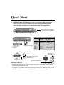
Quick Start
1. Install the Express 10/100 Switch in a rack or on a shelf or table and plug the
cord in. If you’re in Europe or Asia, or any other country that has a 220-volt
electrical system, set the power supply switch to 230 (115 is the default).
Otherwise, leave the switch set to 115. Turn the power on.
Brackets and screws for standard
19-inch equipment rack placement.
Rubber feet for shelf or table placement.
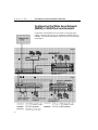
2. Connect the network devices to the switch.
Cabling Guidelines
Crossover cables
to hubs or other
switches.
Straight-through cables
to servers/workstations.
at 10 Mbps
at 100 Mbps
Server/
Workstation
to Switch
CAT 3, 4, or 5
straight-through
CAT 5
straight-through
Hub to
Switch
CAT 3, 4, or 5
crossover
CAT 5 crossover
Switch to
Switch
CAT 3, 4, or 5
crossover
CAT 5 crossover
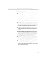
3. Check the LEDs for power and links.
Always on.
Lights when a
device is attached.
Lights briefly while the switch
performs self-tests.
Blinks every two seconds.
Lights when a 100BASE-TX
device is attached.
Next steps (Optional)
• Continue to the next page if you want to configure the switch to work with an SNMP-compliant
Network Management System (NMS).
• See Chapter 2 if you want to use the Console Manager to change port configurations (set a port for
full duplex or manually set the speed), assign an IP address, or check port statistics.
1
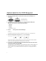
(Optional) Quick Start for SNMP Management
4. Use the null-modem cable to connect the Console port to a COM port on a
workstation.
A null-modem cable is
provided with the switch.
5. Open a terminal emulation program (such as HyperTerminal in Microsoft
Windows* 95). Use these communication parameters:
•
•
•
•
•
9600 baud
8 data bits
No parity
1 stop bit
Xon/Xoff flow control
6. Press E and log into the Console Manager:
Login:
password:
By default, no password or user name is assigned. If you enter one, it’s saved upon reset.
7. Set the IP configuration using the set-ip-conf command:
set-ip-conf 192.1.1.64 255.255.255.0 192.1.1.255 E
IP address
netmask
broadcast address
Replace these addresses with the numbers for your network. Specify the IP address, netmask
(subnet mask), and broadcast address (default gateway), in that order.
8. Download the Intel MIB (Management Information Base) file from an Intel online
service and compile it into your NMS.
The MIB filename is SWCH2MIB.EXE. You can find the file on Intel’s Customer Support web
site (http://support.intel.com) or the Intel BBS (Host: ftp.intel.com, Directory: pub/support/
enduser_reseller). See your NMS documentation for instructions on compiling the MIB for a
new device.
2
1
Hardware Installation
and Network
Topology
Overview
The Intel Express 10/100 Fast Ethernet Switch features eight autonegotiating 10BASE-T/100BASE-TX ports. Each port supports an
Ethernet (10 Mbps) or Fast Ethernet (100 Mbps) segment. The switch
also has two slots for optional two-port media adapters (such as
100BASE-TX or 100BASE-FX).
The switch also has a built-in SNMP (Simple Network Management
Protocol) agent and can be monitored and controlled through any
SNMP-compliant Network Management System (NMS), such as Intel
LANDesk® Network Manager. See page 21 for information on using
the switch with an SNMP NMS and getting the switch’s MIB.
3
C H A P T E R
1
Intel Express 10/100 Fast Ethernet Switch
Installation and Setup
1
Install the switch in a rack or on a shelf.
For rack placement, connect the switch to a 19-inch rack using the
enclosed rack mount brackets.
For shelf placement, attach the enclosed rubber feet to each corner of
the bottom of the switch and place it on a flat, level surface.
2
WARNING
If you’re in a country that has
a 220-volt electrical system,
you must set the power
switch to 230.
Plug the switch in and turn the power on.
Plug the switch into an active AC outlet and turn the power on. If
you’re in Europe or Asia, or any other country that has a 220-volt
electrical system, set the power supply switch to 230 (115 is the
default). Otherwise, leave the switch set to 115.
Most European and Asian
countries have 220-volt
systems.
The United States and Japan both have 110 volt systems.
The power cord is a North
American type, UL-listed/
CSA-certified power supply
cord. Immediately discard
this cord if it is inappropriate
for the electrical system of
your country, and obtain the
proper cord as required by
your national electrical codes
or ordinances and certified
for use in your region.
Follow these general guidelines:
3
Connect the 10BASE-T or 100BASE-TX devices.
•
You don’t need to manually set the speed. The switch
automatically detects the speed of the connected devices.
•
Always use Category 5 unshielded twisted-pair (CAT 5 UTP)
cable when connecting 100BASE-TX devices. You can use
CAT 3, 4, or 5 UTP for 10BASE-T devices.
•
Limit the distance between devices connected with UTP cable to
100 meters.
•
Use a crossover cable when directly connecting a hub (also called
a repeater or concentrator) to the switch. Use straight-through
cables when connecting to servers or workstations. If you don’t
have a crossover cable, use the MDI connector on port 1 to
connect a hub.
•
Configure the network so devices that talk primarily to each other
are on the same segment. Each port is a single segment.
4
Is setup complete?
If you’re using the switch as a stand-alone device (not under the
control of network management software), you’re done.
If you want to change the default configuration (shown in
Appendix A) or manage the switch, continue to Chapter 2.
4
C H A P T E R
1
Hardware Installation and Network Topology
Using the Switch
The switch requires minimal user intervention. It automatically learns
the addresses of new devices as you connect them, and will relearn
addresses dynamically if you reconfigure the network. It also
automatically detects the speed of connected devices. You don’t need
to manually set the speed.
Port status LEDs
Ports on the switch are wired
MDI-X for connection to MDI
ports using a straight-through
UTP cable. See page 8 for
more information.
NOTE
The default configuration of
all ports is half-duplex mode.
To change to full duplex, use
the Console Manager. See
page 22 for instructions.
Port LEDs provide information about each port’s configuration and
the status of devices connected to the ports.
Xmt
Transmit. Lights when the switch is transmitting
packets from this port to another port. Normally
blinks at regular intervals, even if no devices are
connected, while it updates the internal SNMP
agent.
Rcv
Receive. Lights when packets are received on this
port, even if they are not forwarded.
Coll/Fdpx Collision (default) or Full Duplex. Blinks when
collisions are detected. Collisions are normal in an
Ethernet environment. However, if the collision
LED is on continuously, you may have a problem
with a device on the segment.
If you’ve enabled full duplex on the port, the LED is
on solid. When full duplex is enabled, collisions
aren’t possible because packets are sent and
received on their own wire pair, so they can’t
collide.
5
C H A P T E R
1
Intel Express 10/100 Fast Ethernet Switch
Flow
Flow control. Lights whenever too much traffic is
entering on a port. When this happens, the switch’s
buffers fill and it’s forced to back pressure the
traffic out to the segment for retransmission. This
allows the switch’s buffers to clear before the
segment retransmits the traffic. See page 73 for a
description of flow control.
100
Speed. Lights when a 100BASE-TX device is
connected to the port. The LED is off when a
10BASE-T device is connected.
Link
Link. When solid, indicates a connection is
established. If the Link LED is off, check for loose
cable connections. Also, make sure you’re using the
correct type of cable, either straight-through or
crossover. See page 8 for more information.
Management status LEDs
Management status LEDs provide information about the overall
operation of the switch and its SNMP management components.
Use these communications
settings when accessing the
built-in Console Manager
application. See page 16 for
more information.
SNMP
Simple Network Management Protocol. Always
on, indicating the built-in SNMP agent is working.
Mgmt
Management. Blinks on at regular intervals as the
SNMP agent is polled for updated information.
Power
Power. Indicates the status of the power supply. The
LED is normally on. It may remain off for a few seconds
during the power-on self-test.
Fault
Fault. Indicates that the switch has detected a
problem. It may remain on for a few seconds during the
power-on self-test. If this indicator blinks or remains lit
after self-test, there’s a problem with the switch.
See Chapter 4 for troubleshooting information.
6
C H A P T E R
1
Hardware Installation and Network Topology
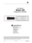
Cabling Requirements
Incorrect cabling is often the cause of network configuration
problems. It’s important that you understand cabling requirements
before connecting devices to the switch.
UTP requirements
The 100BASE-TX Fast Ethernet specification requires you use
Category 5 unshielded twisted-pair (CAT 5 UTP) cabling to operate at
100 Mbps per second. If you use lower grade cabling (CAT 3 or
CAT 4), you may get a connection, but will soon experience data loss
or slow performance.
The 10BASE-T Ethernet specification allows you to use CAT 3,
CAT 4, or CAT 5 UTP cabling.
You’re limited to 100 meters between any two devices with UTP
cable whether you’re running at 10 Mbps or 100 Mbps. However, you
can extend the total diameter by installing a fiber optic media adapter
and using fiber optic connections between switches, or between the
switch and a hub (repeater), router or bridge. See page 12 for an
example.
Fiber optic requirements
The optional 100BASE-FX fiber optic media adapter (Intel product
code ES101MAFX) lets you use multimode fiber optic cable to
connect two switches, or to connect the switch to a hub, bridge, or
router. The media adapter uses an SC fiber optic connector.
With multimode fiber optic cable, signals can travel up to 412 meters
between two switches or between the switch and a router when the
link is configured at half duplex. If configured at full duplex, the
signal can travel up to 2 kilometers.
The signal can travel up to 160 meters between the switch and a hub
(repeater). Full duplex isn’t possible between the switch and a hub.
7
C H A P T E R
1
Intel Express 10/100 Fast Ethernet Switch
Straight-through vs. crossover cables
Ports on the switch are wired MDI-X so you can use a straightthrough cable when connecting to a workstation or server (adapter
cards are wired MDI). For direct connection to another MDI-X port
(most hubs and some switches), you must use a crossover cable.
NIC RJ-45 (MDI)
Switch/Hub RJ-45 (MDI-X)
NOTE
When making your own
cables, wires 1 and 2
must be a twisted pair
and 3 and 6 must be a
twisted pair.
A straight-through
(standard) cable connects
MDI ports to MDI-X ports.
Switch/Hub RJ-45 (MDI-X)
Switch/Hub RJ-45 (MDI-X)
A crossover cable
connects MDI-X ports to
MDI-X ports (or MDI ports
to MDI ports).
8
C H A P T E R
1
Hardware Installation and Network Topology
Determining which cable to use
Different switch and repeater manufacturers implement their port
configurations differently. The following guidelines are based on the
Express 10/100 Switch, the Intel Express 100BASE-TX Stackable
Hub (repeater) and the EtherExpress™ family of adapters (server or
workstation). These apply to the majority of switches and hubs and all
servers or workstations:
For this connection
Use this cable
Switch to repeater
Crossover
Switch to server or workstation
Straight-through
Switch to switch
Crossover
Repeater to server or workstation
Straight-through
Port 1 on the switch has both an MDI and MDI-X connector. If you’re
not seeing a link on a port, try plugging into each of the port 1
connectors.
9
C H A P T E R
1
Intel Express 10/100 Fast Ethernet Switch
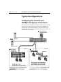
Typical Configurations
Configuring the mixed 10 and
100 Mbps workgroup environment
In the mixed 10 and 100 Mbps environment, workgroup clients should
be connected to a hubs such as the Intel Express 10/100BASE-TX
Stackable Hub. All hub stacks should be connected to the Express
10/100 Switch. Servers or busy workstations should also be connected
directly to the 10/100 Switch.
Segment 1
10
Segment 2
C H A P T E R
1
Hardware Installation and Network Topology
Configuration guidelines:
Servers or workstations: Configure servers or workstations
directly connected to the switch for full duplex. Since the traffic is
two-way traffic, you’ll see a performance increase with a full
duplex configuration. See page 22 for instructions on configuring
full duplex.
Security considerations: If you have concerns about server
access or other security issues, configure security virtual LANs
(SVLANs) to prevent segments (ports) from accessing other ports.
In the example on the previous page, you may want to prevent
workstations on the 10 Mbps hub on port 4 from accessing the file
server on port 2. See page 23 for more information on configuring
SVLANs.
100 Mbps or 10 Mbps hubs: Leave hubs (repeaters) at half
duplex with flow control enabled. Since hubs broadcast traffic
among all ports and full duplex requires a point-to-point
connection, you can’t configure a 10 or 100 Mbps hub for full
duplex.
11
C H A P T E R
1
Intel Express 10/100 Fast Ethernet Switch
Configuring the Wide Area Network
(WAN) or multi-floor environment
Connections to the backbone are most effective using fiber optic
cabling, especially when devices are separated by multiple floors or
buildings. This extends the distance between devices to 2 kilometers
at full duplex.
12
C H A P T E R
1
Hardware Installation and Network Topology
Configuration guidelines:
Fiber optic connections to switches or routers: Use multi-mode
fiber to connect to a router or another switch. You must purchase
a 100BASE-FX expansion module separately (Intel order code
ES101MAFX). Each module comes with two ports.
If the switch or router is capable of full duplex, the maximum
cable length between the two devices is 2 kilometers. At half
duplex the maximum is 412 meters.
Two-port 100BASE-TX expansion are also available (Intel order
code ES101MATX).
Full duplex and flow control between Express 10/100 switches:
The only time you can configure full duplex and flow control
simultaneously is between two Express 10/100 switches. Special
information is added to packets between switches to accomplish
this. This works with both fiber optic and CAT 5 cabling.
Fiber optic connections to repeaters: Since repeaters aren’t
capable of full duplex mode operation, you’re restricted to 160
meters of fiber optic cable between the Express Switch and a
repeater.
Multi-workgroup server configuration: Always put servers
accessed by multiple workgroups off of the switch. Because the
server has a point-to-point connection, you can configure it for
full duplex and increase the bandwidth of the connection. Note
that the adapter in the server must be capable of full duplex.
Network administrator’s workstation: Connect the
administrator’s workstation directly to the switch. This reduces
the risk of the administrator getting dropped off the network and
allows the administrator to get network information faster.
Local workgroup server configuration: Always connect servers
accessed by local workgroups to a hub, not to the switch. This
reduces the amount of traffic passing through the switch and
improves the performance for all workgroups connected to it.
However, if more than one workgroup accesses a server, connect
the server directly to the switch.
13
C H A P T E R
1
Intel Express 10/100 Fast Ethernet Switch
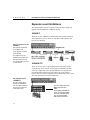
Repeater count limitations
The switch doesn’t count as a repeater. Each port on the switch can
support a full Fast Ethernet or Ethernet network.
10BASE-T
There can be four 10BASE-T repeaters/hubs between the switch and
any workstation or server. However, only three of the repeaters can
have devices attached.
5-4-3-2-1 general rule for
10BASE-T
Five segments are allowed
Four repeater hops
Three repeaters can have
nodes attached
Two segments can’t be
populated and are links only
All of this makes One collision domain with a maximum
of 1024 stations.
100BASE-TX
There can be one class 1 repeater/hub between the switch and any
workstation or server (a stack of Intel Express 100BASE-TX Hubs
counts as a single hub). Also, the total diameter of a segment can’t
exceed 200 meters when using UTP cable. That is, the distance
between any two nodes on a segment (or the switch and a node on the
other side of a hub) can’t exceed 200 meters.
One repeater hop for
100BASE-TX
Only one repeater hop is
allowed for 100BASE-TX.
Also, the distance between
the node and switch can’t
exceed 200 meters.
14
You can’t daisy-chain 100
Mbps hubs with UTP
cable.
For Express 100BASE-TX
hubs, use cascade cables.
For other 100 Mbps hubs,
see the documentation
that came with the hub.
2
Configuring and
Managing the Switch
You don’t need to read this chapter or Chapter 3 unless you want to
change the Express 10/100 Fast Ethernet Switch’s default
configuration (see Appendix A for a list of defaults) or intend to
manage the switch. The switch is ready to go simply by plugging it in
and turning the power on.
However, if you need to change the default configuration or manage
the switch, there are two ways:
•
Use SNMP-compliant management software such as Intel
LANDesk Network Manager (not included).
•
Use the Express 10/100 Switch’s internal Console Manager either
by directly connecting a serial cable or through Telnet.
To use SNMP management software or Telnet to the switch, you must
first connect to the switch using a serial cable and use the Console
Manager to assign an IP address.
15
C H A P T E R
2
NOTE
For more information about
any of the commands used in
this chapter, see Chapter 3,
Console Command Reference.
Intel Express 10/100 Fast Ethernet Switch
Accessing the Console
Manager
The Console Manager software is contained in the switch’s
nonvolatile RAM (NVRAM). You don’t need to install any software.
To access the Console Manager:
NOTE
1
Use the null-modem cable (included with the switch) to connect a
workstation’s COM port to the Console port on the switch.
2
Open a terminal emulation program (such as HyperTerminal in
Windows 95).
3
Select the COM port and these communication parameters:
In HyperTerminal, you must
set flow control (unrelated to
the switch’s flow control
feature) to Xon/Xoff.
9600 baud, 8 data bits, no parity, 1 stop bit, Xon/Xoff flow control
(To set these parameters in HyperTerminal, choose Properties
from the File menu. Then click the Configure button.)
4
Press E. The login prompt appears:
Please Login
username:
password:
By default, no username or password is assigned. If you enter a
password, it becomes active only after you reset the switch or turn
off the power. If you want the password to take effect
immediately, use the set-passwd command.
Accessing the Console Manager remotely
To access remotely through Telnet, first set the IP configuration of the
switch using the set-ip-conf command through the Console port (see
page 21 for instructions). Then use Telnet to reach the switch.
All commands work as if a terminal were directly connected to the
Console port. Only one console session can be active at a time (either
local or remote). After the first Telnet session is established, other
Telnet connections are refused until the current session is closed.
16
C H A P T E R
2
Configuring and Managing the Switch
Using the Console Manager
The Console Manager provides an out-of-band (not on the network)
connection to the switch. Use the Console Manager to
•
assign an IP configuration to the switch.
•
configure the ports.
•
monitor network performance.
•
create VLANs.
Entering commands
To enter commands, type the command name followed by any
parameters and press E. For example, typing sys-stat E
at the command prompt displays basic system status information.
Items in angle brackets mean you need to enter a specific value. For
example, <IPaddress> represents an IP address in dotted decimal
notation (such as 123.1.1.7).
Items in { } and separated by | represent alternatives for an
argument. For example,
get-comm {read|write|*}
means you can type one of the following
get-comm read
get-comm write
get-comm *
If you enter a command incorrectly, a message indicates the type of
error. For example, typing a nonexistent command gives the message:
SYS_console> pin
command <pin> not found
Entering an existing command with an incorrect number of
parameters displays this message:
SYS_console> ping
too few arguments
17
C H A P T E R
2
Intel Express 10/100 Fast Ethernet Switch
Some commands have parameters that determine how settings are
saved and when they’re implemented. Some are changed in
•
the running configuration so that the new value is used
immediately (the run option).
•
the NVRAM so that the changes are saved and occur only in the
next session (the nvram option).
•
both the running and the NVRAM configuration (the all option).
For an explanation of a command’s parameters, add a question mark
(?) after the command name:
SYS_console> set-lt-age ?
set-lt-age
sets the LT aging period
[arg #0] database type - either {run|nvram|all}
[arg #1] aging time in seconds
The Console Manager provides a history of the last several commands
you entered. To cycle through them, press ! or cP at the prompt.
To correct a command line, use the following special keys (see the
command):
help-kbd
•
! or cP
for the previous command
•
cW
to delete the previous word
•
cU
to delete the entire line
When you type a command that results in more than one screen of
text appearing, you can press Q to stop the process or any other key
to continue to the next screen.
You can press T to see the list of commands that start with the
text already typed. For example:
SYS_console> get-c T
Commands matching <get-c>
---------------------------------------------------
18
get-comm
show current read or/and write community
get-con-matrix
displays the VLAN connectivity matrix
get-colls-cnt
gets the collision distribution counters per port
C H A P T E R
2
Configuring and Managing the Switch
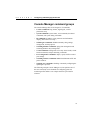
Console Manager command groups
The Console Manager has several categories of commands:
•
Console commands: help, banner, login/logout, console
parameters setup.
•
System commands: system status, reset commands, download
commands, and system debug commands.
•
IP commands: IP address setup, parameter and information
display, and remote boot setup.
•
SNMP agent commands: SNMP community string settings,
management, and trap options.
•
Switching database commands: aging time management and
switching database entry management.
•
VLAN commands: management of security virtual LANs, virtual
broadcast domains, and port mirroring commands.
•
Port configuration commands: duplex, speed, and flow control
port settings.
•
Switching statistics commands: RMON and Ethernet traffic and
packet counters.
•
Spanning tree commands: disabling or manually configuring the
spanning tree protocol.
The following example Console Manager session explains some of
the more commonly used commands for configuring ports and
monitoring traffic statistics. An example network is provided for
reference.
19
C H A P T E R
2
Intel Express 10/100 Fast Ethernet Switch
Sample Console Manager
Session
Refer to the diagram below when reading the sample configuration
procedures on pages 21 through 29.
Procedures using this diagram
• Configuring the SNMP agent for IP (page 21)
• Configuring a port for full duplex (page 22)
• Creating VLANs (page 23)
• Monitoring traffic (page 25)
20
C H A P T E R
2
Configuring and Managing the Switch
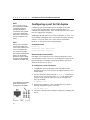
Configuring the SNMP agent for IP
You can monitor and control the switch through any SNMP-compliant
network management system (NMS). First, you must configure the
SNMP agent by assigning an IP address.
In the diagram on page 20, a laptop is used to connect to the switch’s
serial port. You must connect directly to the serial port for first-time
IP configuration. See page 16 for more information on connecting to
the switch via the serial port.
Commands used
set-ip-conf <ip address> <netmask> <broadcast address>
ping <ip address> <number|0>
NOTE
If you don’t specify an IP
configuration, the agent
won’t respond to any in-band
requests, including ping
messages and network
management applications.
To configure the SNMP agent
1
Set the IP configuration. Type the command:
set-ip-conf 192.1.1.64 255.255.255.0 192.1.1.255
IP address
netmask
broadcast address
Replace the numbers with those for your network. If the switch
doesn’t have an IP configuration (default), then the specified IP
configuration is used immediately and saved in NVRAM.
192.1.1.255 is the address of the router in the diagram on page 20.
If you previously assigned an IP configuration, the command
changes only the NVRAM. To use the new parameters, reset the
switch using the warm-reset command.
2
Test the installation. Type the command:
SYS_console> ping 192.1.1.1 2
This example tests connectivity from the switch to the network
administrator’s workstation (IP address 192.1.1.1). The option 2
tells the switch to send two requests. Use 0 for an endless ping.
For more information on the ping command, see page 46.
3
Download the MIB from Intel’s Customer Support World Wide
Web site (http://support.intel.com). The file is compressed in the
file SWCH2MIB.EXE.
4
Compile the MIB into your NMS. See your NMS documentation
for more information.
You can now access the switch remotely with your NMS or through
Telnet.
21
C H A P T E R
2
NOTE
You must have a point-topoint connection to establish
a full-duplex connection
(shared hubs/repeaters/
concentrators aren’t capable
of full duplex). Additionally,
both points of the connection
must be configured for full
duplex.
Intel Express 10/100 Fast Ethernet Switch
Configuring a port for full duplex
Configuring a port for full duplex allows the switch to send and
receive packets simultaneously with the destination device. To
establish a full-duplex link, the switch and the destination device both
must be configured for full duplex.
Additionally, the link must be to a switch, workstation, or server. You
can’t establish a full-duplex link to a device that broadcasts incoming
packets to every port on the device. This excludes shared hubs,
repeaters, or concentrators from using full duplex.
NOTE
Setting a port to full duplex
automatically disables flow
control. Since collisions don’t
occur on a full-duplex link,
flow control isn’t possible.
Commands used
One exception is between two
Express 10/100 switches.
Special information is added
to packets traveling between
switches to accomplish this.
Recommended environments
get-port-cfg
set-speed-sel <port> {asense|10|100}
set-port-dplex <port> {full|half}
Full duplex is best when two devices exchange information to and
from each other (such as a file server). In the diagram on page 20, the
Payroll and Finance 100 Mbps workgroups frequently copy files to
and from the file server on port 5.
To configure a port for full duplex
The Coll/Fdpx LED is solid
green when the port is
configured for full duplex.
1
Configure the device on the other end for full duplex. In the
diagram on page 20, you’d configure the adapter in the file server
for full duplex.
2
Get the current port settings using the get-port-cfg command. If
the port is set to autosense the speed (asense is the default) then
you must set the speed to either 10 or 100. This example sets
port 5 to 100 Mbps.
set-speed-sel 5 100
3
Set the port to full duplex. (This command fails is you haven’t
manually changed the speed to 10 or 100).
set-port-dplex 5 full
4
22
Check the Coll/Fdpx LED. It should be solid green, indicating full
duplex.
C H A P T E R
2
Configuring and Managing the Switch
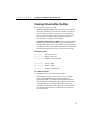
Creating Virtual LANs (VLANs)
You can create two types of VLANs:
•
Security VLANs (SVLANs). Ports in an SVLAN can exchange
frames only with other ports in the same SVLAN. SVLANs are
used for security to prevent access to devices on the network.
They’re also used to reduce unnecessary traffic on the network
since all traffic, including broadcast and unicast frames, is
prevented from crossing SVLAN boundaries.
•
Virtual Broadcast Domains (VBDs). Ports in a virtual broadcast
domain can exchange broadcast frames only with other ports in
the same VBD. However, they can exchange unicast frames with
any other port on the switch. VBDs reduce broadcast traffic on the
network, while allowing other types of traffic to pass through.
Commands used
set-sec-vlan
Sets up an SVLAN.
del-sec-vlan
Deletes an SVLAN.
get-svlan-tbl
Displays the SVLAN table.
set-vbc-domain
Sets up a VBD.
del-vbc-domain
Deletes a VBD.
get-vbc-tbl
Displays the VBD table.
To create an SVLAN
1
Determine the ports you want to group together.
In the diagram on page 20, the file server on port 5 contains
sensitive information that only the Payroll and Finance
workgroups should see. Creating an SVLAN that includes the
Payroll and Finance workgroups along with the file server will
accomplish this. However, Payroll and Finance still need to
communicate with stations on the other ports. Creating another
SVLAN that includes all ports except the file server port will
solve this problem.
23
C H A P T E R
2
Intel Express 10/100 Fast Ethernet Switch
2
Create the two SVLANs. Type the commands:
set-sec-vlan all 3-5-7
set-sec-vlan all 1-2-3-4-6-7-8
These commands create two SVLANs and saves the entries in
NVRAM. Replace all with nvram to save the entry without
changing it immediately or with run to change the entry now
without saving it.
3
To display a summary of saved SVLANs, type:
get-svlan-tbl nvram
Any SVLANs created with the nvram or all options are displayed.
To create a VBD
1
Determine the ports you want to group together.
The Engineering workgroup on port 8 experiences a high volume
of traffic just within its own workgroup. Broadcast traffic from
other workgroups adds to the problem. By grouping port 8 and
port 6 into a VBD, the Engineering workgroup can access the
common application server on port 6 while being shielded from
the rest of the network’s broadcast traffic.
However, this configuration prevents ports 1-4 and 7 from seeing
the application server. Another VBD that includes ports 1-4 and
6-7 will allow other ports to reach the file server.
2
Type the commands:
set-vbc-domain run 6-8
set-vbc-domain run 1-2-3-4-6-7
These VBDs are temporary (only until the next reset or power
down). To save the entries for future use and have them take
effect now, replace run with all.
3
To display a summary of saved VBDs, type:
get-vbc-tbl nvram
24
C H A P T E R
2
Configuring and Managing the Switch
Monitoring traffic
Use monitoring commands to determine the traffic volume from
specific ports or between ports. This information helps you determine
the network’s traffic patterns so you can adjust your network topology
for maximum efficiency.
Make sure you get a good statistical representation of your network.
Take a reading when users log on in the morning and pull files from
servers and another during breaks or when users log off at night—any
time you think the network is experiencing heavy traffic. This gives
you a baseline for comparison when problems arise on the network.
Statistics are generated for the current session. Reset counters by
using the clr-cnt command, warm-reset command, or by cycling the
power.
In general, keep devices that talk primarily to each other on the same
segment (remember, each port is an Ethernet segment). For example,
if a high volume of traffic is forwarded from the CD server on port 4
to the payroll workgroup on port 3, but no other workgroups access
the CD server, move the server to the hub on port 3 instead of the
switch. This change may not be efficient, however, if users from the
payroll, marketing, or finance workgroups also access the CD server.
Under heavy traffic loading conditions, the Console Manager may
understate the Ethernet statistical counts. You can also use a protocol
analyzer to monitor the segment the port is attached to. See step 8 on
page 72 for configuration details.
Commands used
get-br-cnt <port>
Displays the packet statistics for a port.
get-eth-cnt <port>
Displays the Ethernet statistics for a port.
get-colls-cnt <port>
Displays the collision distribution counters
for a port.
get-rmon-cnt <port>
Displays the Ethernet RMON counters for a
port.
get-sdist-cnt <port>
Displays the packet size distribution counters
for a port.
get-mgm-brcnt
Displays the statistics for the SNMP agent.
clr-cnt
Resets the Ethernet and bridging statistics.
25
C H A P T E R
2
Intel Express 10/100 Fast Ethernet Switch
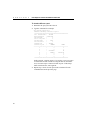
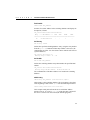
To check traffic on a port
1
Determine the port you want to check.
2
Type the command. For example:
SYS_console> get-br-cnt 3
Ethernet Switching Counters for port 3
====================================================
Frm
Received OK :
1419681
Bytes Received
: 842637991
Frm Filtered
:
0
Frm to all ports :
0
Frm multicast
:
16017
Frm lost/fctrl
:
0
Transmit OK
:
1404387
Forward to port
:
FRAMES
BYTES
----------------------------------------------------1
:
0
0
2
:
0
0
3
:
218103808
60
4
:
1419823
842711315
5
:
0
0
6
:
0
0
7
:
0
0
====================================================
In this example, a station on port 3 is accessing a server on port 4.
To reduce the amount of traffic crossing the switch, connect the
server to a hub on port 3 instead of a hub on port 4. This keeps
traffic localized to the same segment.
3
26
Repeat steps 1 and 2 for each port on the switch and for each
command listed on the previous page.
C H A P T E R
2
Configuring and Managing the Switch
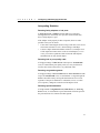
Interpreting Statistics
Detecting faulty adapters or hub ports
If Too Long errors or Jabbers (packets that are too long and
misaligned) occur consistently on a port, the connected node may
have a faulty adapter or port.
If the adapter works properly in other computers, there are other
possible causes you can check:
•
Is the cable connecting the node too long? UTP cable can’t exceed
100 meters and must be CAT 5 when running at 100 Mbps.
•
Is there a duplex mismatch with the switch? If a switch port is set
to full duplex and connected to a node set to half duplex, or vice
versa, you could see problems. Hubs such as the Intel Express
Stackable hub can only be half duplex.
Detecting bad or poor quality cable
If a high percentage of CRC Errors with respect to Transmit OK
occur, it could indicate poor quality cable or a noisy environment.
Test the cable with a cable tester or try a different cable.
Detecting congested segments
If a high percentage of Exces Coll Errors or Exces Fctrl Errors with
respect to Transmit OK occur, it could indicate a congested segment.
Balance the traffic load by moving the destination devices to local
segments. If the port is attached to a workstation, server, or switch
(not a repeater), change the connection to full duplex mode.
Detecting speed mismatches
If a high amount of Alignment Errors, Runt Errors, or Too Long
Errors occur, it could indicate a speed mismatch. Check the speed of
the port and all devices connected to that segment.
27
C H A P T E R
2
Intel Express 10/100 Fast Ethernet Switch
Statistic Definitions
Transmit OK: The number of valid frames sent from the port.
Underflow Errors: Internal error. A normal ratio of this counter to
the Transmit OK counter is 1% or less.
Exces Coll Errors: Increments when the port unsuccessfully
transmits a packet 16 consecutive times.
Exces Fctrl Errors: Increments when the port applies flow control
16 consecutive times. See page 73 for more information.
Receive EOF: Total number of frames received at this port.
Receive OK: The number of valid frames received at this port.
Overflow Errors: Internal error. A normal ratio of this counter to the
Transmit OK counter is 1% or less.
CRC Errors: The number of packets received that had a length
(excluding framing bits, but including FCS octets) of between 64 and
1518 octets and had a bad Frame Check Sequence (FCS) with either
an FCS Error or an Alignment Error.
Alignment Errors: The number of frames detected that contain
partial octets and don’t pass the FCS check.
Runt Errors: The number of frames detected that are less than the
minimum permitted frame size and have a good FCS.
Lost/Fctrl Errors: The number of packets lost (if flow control is
disabled) or number of packets retransmitted by the originator due to
flow control (if flow control is enabled).
Too Long Errors: The number of frames detected that exceed the
maximum permitted frame size.
etherStatsOctets: The number of octets (bytes) of data (including
those in bad packets) received on the network (excluding framing bits
but including FCS octets).
etherStatsPkts: The number of packets received by the port. This is
not a good indication of total network traffic since packet vary in size.
The number of octets gives a better estimate of network traffic.
etherStatsBcastPkts: The number of frames that are detected without
errors and are directed to the broadcast group address. Doesn’t include
multicast frames or frames received with Too Long, Runt, FCS, or
Alignment errors.
28
C H A P T E R
2
Configuring and Managing the Switch
etherStatsMcastPkts: The number of frames that are detected
without errors and are directed to a non-broadcast group address. This
doesn’t include frames received with Too Long, Runt, FCS, or
Alignment errors.
etherStatsCRCAllignPkts: The number of packets received that had
a length (excluding framing bits, but including FCS octets) of
between 64 and 1518 octets and had a bad Frame Check Sequence
(FCS) with either an FCS error or an Alignment error.
etherStatsUndersizePkts: The number of packets received that were
less than 64 octets long (excluding framing bits, but including FCS
octets) but were otherwise well-formed.
etherStatsOversizePkts: The number of packets received that were
longer than 1518 octets (excluding framing bits, but including FCS
octets) but were otherwise well-formed. Might indicate VLAN frames
entering the port.
etherStatsRuntPkts: The number of frames detected that are less
than the minimum permitted frame size and have a good FCS.
etherStatsJabberPkts: The number of packets received that were
longer than 1518 octets (excluding framing bits, but including FCS
octets), and had a bad Frame Check Sequence (FCS) with either an
FCS error or an Alignment error. The allowed range to detect jabber
is between 20 and 150 ms. This is usually caused by a malfunctioning
network adapter.
etherStatsCollisions: The number of collisions on this Ethernet
segment (port).
etherStatsPkts64Octets: Number of packets 64 octets in length (the
minimum size of an Ethernet packet).
etherStatsPkts65to127Octets: Number of packets 65 to 127 octets in
length.
etherStatsPkts128to255Octets: Number of packets 128 to 255 octets
in length.
etherStatsPkts256to511Octets: Number of packets 256 to 511 octets
in length.
etherStatsPkts512to1023Octets: Number of packets 512 to 1023
octets in length.
etherStatsPkts1024to1518Octets: Number of packets 1024 to 1518
octets in length (1518 is the maximum size of an Ethernet packet).
29
3
Console Command
Reference
Type ? at the Console Manager prompt to display the list of available
command groups and a short explanation of each. Type the name of a
group to display commands relevant to that group.
SYS_console> ?
Commands groups are:
--------------------------------------------------console
Console related commands
system
System related commands
ip
IP related commands
snmp
SNMP related commands
switch-db
Switching Database related commands
vlan
Virtual LANS related commands
port-cfg
Port Configuration related commands
statistics
Switching Statistics related commands
sp-tree
Spanning Tree related commands
-----------------------------------------------------------use ! for prev. cmd, ^U to clr line, ^W to clr previous word
------------------------------------------------------------
When you find the command you want, type its name followed by ?
for a description of command syntax.
31
C H A P T E R
3
Intel Express 10/100 Fast Ethernet Switch
Console Command-line Summary
Console Commands
help-kbd
Lists the help and shortcut keys.
banner
Displays the Console Manager logo.
clear
Clears the screen.
login
Exits Console Manager and displays the login screen.
logout
Exits Console Manager and any active Telnet session.
set-prompt <new_prompt>
Changes the console prompt.
set-passwd
Changes the console password.
System Commands
sys-stat
Displays system status.
get-stst-level
Displays the selftest level.
set-stst-level {none|short|long}
Changes the selftest level.
warm-reset
Performs a warm reset of the switch.
cold-reset
Performs a cold reset of the switch, which is the same as powering it off then on again.
get-last-err
Displays information about the last fatal error.
init-nvram
Resets nonvolatile RAM (NVRAM) to default values.
set-line-slip {9600|19200|38400}
Transfers the serial connection to SLIP mode and sets the baud.
get-sw-file
Displays the SNMP agent software filename.
32
C H A P T E R
3
Console Command Reference
set-sw-file <filename>
Sets the SNMP agent software filename for download.
get-rsw-file
Displays the SNMP agent software remote filename.
set-rsw-file <filename>
Sets the SNMP agent software remote filename for download.
get-tftp-srvr
Displays the IP address of the TFTP server.
set-tftp-srvr <IPaddress>
Sets the TFTP download server IP address.
sw-dnld
Starts the SNMP software download from the defined TFTP server.
get-par-file
Displays the SNMP agent parameters filename.
set-par-file <filename>
Sets the SNMP agent parameters filename for automatic setup.
set-fg-param <dest> <source> <fill_byte> <length>
Sets the Ethernet frame generator parameters.
start-fg <dport-bitmask> <count> <rate>
Starts the Ethernet frame generator.
stop-fg
Stops the Ethernet frame generator.
IP Commands
get-ip
Displays the current IP address.
set-ip <IPaddress>
Sets the IP address.
get-ip-conf
Displays the current IP address, netmask, and broadcast address.
set-ip-conf <IPaddress> <netmask> <broadcast>
Sets the IP address, netmask, and broadcast address.
set-slip <IPaddress>
Sets the SLIP address.
get-slip
Displays the SLIP address.
get-slip-conf
Displays the current SLIP configuration.
33
C H A P T E R
3
Intel Express 10/100 Fast Ethernet Switch
set-slip-conf <IPaddress> <netmask> <broadcast>
Sets the SLIP configuration.
get-gatew
Displays the default gateway.
set-gatew <IPaddress>
Sets the default gateway.
get-arp-tbl
Displays the Address Resolution Protocol (ARP) table.
del-arp-entry <IPaddress|*>
Deletes one or all entries from the ARP table.
add-arp-entry <IPaddress> <mac_address> <port>
Adds an entry to the ARP table.
get-bootp
Displays the state of the BOOTP process.
set-bootp
Enables or disables the BOOTP process.
ping <IPaddress> {<number>|0}
Contacts another IP device.
ping-stop
Stops the ping process.
get-def-ttl
Displays the running default TTL (time to live) value.
set-def-ttl <number>
Modifies the running default TTL value.
SNMP Commands
get-comm
Displays the current read or write community.
set-comm {read|write} <community-string>
Changes the read or write community.
get-auth
Displays the trap authentication mode.
set-auth {on|off}
Sets the trap authentication mode.
get-traps
Displays the destination stations in the trap list.
add-trap <IPaddress> <trap-community>
Adds a destination station to the trap list.
del-trap <IPaddress>
Deletes a destination station from the trap list.
34
C H A P T E R
3
Console Command Reference
Switching Database Commands
get-lt-entry <index>
Displays a switching database entry.
get-lt-16 {<index>|*>
Displays 16 switching database entries starting at a given item number.
find-lt-addr <mac_address>
Searches for an address in the switching database.
del-lt-entry <index>
Removes a switching database entry.
del-lt-addr <mac_address>
Removes the switching database entry for a given address.
add-lt-entry <mac_address> {lock-off|lock-on} <dport>
Adds a switching database entry.
add-cf-entry {lock-off|lock-on|perm} <mac_address> <sport> <dport>
Adds a custom filter entry.
del-cf-entry {run|nvram} <mac_address> <sport>
Deletes a custom filter entry.
get-nv-cftbl
Displays the saved custom filters table.
get-nv-cfilt <mac_address>
Displays the saved custom filters for a given MAC address.
get-lt-age
Displays the switching database aging period.
set-lt-age {run|nvram|all> <aging_time>
Sets the switching database aging period.
Virtual LAN (VLAN) Commands
set-vbc-domain {run|nvram|all} <port_list>
Defines a Virtual Broadcast Domain (VBD).
del-vbc-domain {run|nvram|all} <domain_id>
Deletes a VBD.
get-vbc-tbl {run|nvram}
Displays the VBD table.
set-sec-vlan {run|nvram|all} <port_list>
Defines a Security Virtual LAN (SVLAN).
del-sec-vlan {run|nvram} <lan_id>
Deletes an SVLAN.
35
C H A P T E R
3
Intel Express 10/100 Fast Ethernet Switch
get-svlan-tbl {run|nvram}
Displays the SVLAN table.
set-mon-port <port>
Sets the monitoring port.
monitor <port>
Starts port monitoring.
stop-mon
Stops port monitoring.
get-lt-filter <mac_address>
Displays the filter for a given MAC address.
get-con-matrix
Displays the VLAN connectivity matrix.
get-vbc-matrix
Displays the VBC connectivity matrix.
Spanning Tree Commands
get-stp
Displays the spanning tree session state.
set-stp {enable|disable}
Enables or disables the spanning tree for the next session.
get-st-bcfg
Displays the spanning tree bridge parameters.
get-st-pcfg
Displays the spanning tree port parameters table.
get-st-syscfg
Displays the spanning tree system ports configuration.
set-br-prio <priority>
Sets the spanning tree bridge priority.
set-br-maxage <maxage>
Sets the spanning tree bridge maximum age.
set-br-hellot <hello_time>
Sets the spanning tree bridge hello time.
set-br-fwdel <forward_delay>
Sets the spanning tree bridge forward delay.
set-prt-prio <port_number> <port_priority>
Sets the spanning tree port priority.
set-prt-enb <port_number> {enable|disable}
Enables or disables the spanning tree port.
set-prt-pcost <port_number> <path_cost>
Sets the spanning tree port path cost.
36
C H A P T E R
3
Console Command Reference
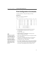
Port Configuration Commands
get-port-cfg
Displays the configuration of all the ports.
set-port-dplex <port-number> {half|full}
Sets a port’s duplex mode to half or full.
set-speed-sel <port-number> {asense|10|100}
Sets a port’s speed to 10, 100, or auto detect.
set-port-fctrl <port-number> {on|off}
Sets a port’s flow control on or off.
Switching Statistics Commands
clr-cnt
Resets the counters for Ethernet and bridging statistics.
get-eth-cnt <port-number>
Displays the Ethernet statistics for a port.
get-colls-cnt <port-number>
Displays the collision distribution statistics for a port.
get-rmon-cnt <port-number>
Displays the Ethernet RMON statistics for a port.
get-sdist-cnt <port-number>
Displays the packet size distribution statistics for a port.
get-br-cnt <port-number>
Displays the switching statistics for a port.
get-mgm-brcnt
Displays the switching statistics of the management port.
37
C H A P T E R
3
Intel Express 10/100 Fast Ethernet Switch
Console Commands
help-kbd
Lists the console function keys.
SYS_console>
? or TAB ! or ^P TAB
^U
^W
-
help-kbd
for a list of the categories
for previous command
for command completion
to clear the line
to clear the previous word
banner
Displays the Express 10/100 Switch Console Manager logo.
clear
Clears the screen and displays the command prompt.
login
Exits the Console Manager, but doesn’t disconnect a Telnet session.
Use this command to password protect the console terminal while a
Telnet session is running.
logout
Ends the local Console Manager session and any Telnet session.
Displays the login prompt for a new session if connected locally.
set-prompt
set-prompt <new_prompt>
Sets the command-line prompt for the Console Manager to a more
meaningful prompt, such as the location of the switch or the name of
a workgroup. The default prompt is SYS_console>.
SYS_console> set-prompt R&D_grp>
CLI prompt change in the NVRAM OK
R&D_grp>
38
C H A P T E R
3
Console Command Reference
set-passwd
Changes the console password. The system first prompts you for the
old password. You then type a new password and retype it for
verification. Passwords never appear on the screen.
SYS_console> set-passwd
Enter old password:
Enter new password:
Enter new password again:
CLI running password changed
CLI password change in the NVRAM OK
If you enter the old password incorrectly or don’t verify the new
password correctly, the password isn’t changed.
System Commands
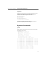
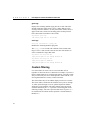
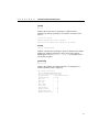
sys-stat
Displays general status information about the switch and its SNMP
agent hardware and software:
SYS_console>sys-stat
Intel Express 10/100 Fast Ethernet Switch
SNMP Agent Software
- Version <version>
SNMP Object ID is : < .1.3.6.1.4.1.629.1.1.3 >
System MAC Address :
00-A0-C9-00-20-D9
Switching Data Base Size :
4096 entries
Total uptime(hundredths of seconds ): 111151888
Total uptime(days, hh:mm:ss format): 12 days, 20:45:18.88
i/f 1 -- description [ Port 1 - 10/100 BaseTx Ethernet Port ] -- status [up]
i/f 2 -- description [ Port 2 - 10/100 BaseTx Ethernet Port ] -- status [up]
i/f 3 -- description [ Port 3 - 10/100 BaseTx Ethernet Port ] -- status [up]
i/f 4 -- description [ Port 4 - 10/100 BaseTx Ethernet Port ] -- status [up]
i/f 5 -- description [ Port 5 - 10/100 BaseTx Ethernet Port ] -- status [up]
i/f 6 -- description [ Port 6 - 10/100 BaseTx Ethernet Port ] -- status [up]
i/f 7 -- description [ Port 7 - 10/100 BaseTx Ethernet Port ] -- status [up]
i/f 8 -- description [ Port 8 - 10/100 BaseTx Ethernet Port ] -- status [up]
i/f 9 -- description [ Port 9 - missing ] -- status [DOWN]
i/f 10 -- description [ Port 10 - missing ] -- status [DOWN]
i/f 11 -- description [ Port 11 - missing ] -- status [DOWN]
i/f 12 -- description [ Port 12 - missing ] -- status [DOWN]
39
C H A P T E R
3
Intel Express 10/100 Fast Ethernet Switch
The screen displays the following information:
•
SNMP agent software version and release date.
•
Device SNMP object ID.
•
Device MAC address.
•
System uptime (in 1/100 of a second) and in days, hours, minutes,
and seconds.
•
Port description and status. Ports 9 through 12 are labeled as
“missing” unless you have optional media adapters installed.
get-stst-level
Displays the self-test level set by the set-stst-level command.
set-stst-level
set-stst-level {none|short|long}
Changes the self-test level. The switch performs a self-test each time
you reset it with the cold-reset command or when you cycle the
power. The default is none.
warm-reset
Resets the SNMP agent software without resetting the switch (it
doesn’t disconnect existing connections). The switch configuration is
loaded from the values saved in NVRAM. This command also resets
the statistics counters.
cold-reset
Performs a cold reset, which is the same as turning the power off then
on again. Any existing connections are lost and the statistics counters
are reset.
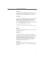
get-last-err
Displays the most recent system failure, if any, for diagnostic
purposes.
SYS_console>get-last-err
System information since the last hardware reset
————————————————————————
Software resets number : 0
The system never encountered a fatal error
40
C H A P T E R
3
Console Command Reference
init-nvram
Resets the NVRAM on the SNMP agent to the default values. The
changes don’t take effect until you use the warm-reset or cold-reset
commands or cycle the power. Appendix A lists the default values.
set-line-slip
set-line-slip {9600|19200|38400}
Changes the console serial port to SLIP mode for out-of-band SNMP
management. The command argument is the new baud for the
interface. You can use SLIP with a terminal server but not with a
modem. Configure the SLIP interface using the set-slip-conf
console command. Return the serial port to console mode by pressing
E three consecutive times from a terminal.
SYS_console> set-line-slip 9600
RS232 baudrate in SLIP mode changed to 9600 bps
To switch back to Administrative Interface Mode press <CR> three
times. Note that the Administrative Interface Mode baudrate will
be 9600
get-sw-file
Displays the name of the SNMP agent software file. The file is stored
internally in the switch.
set-sw-file
set-sw-file <filename>
Sets the name of the file to be downloaded by TFTP (trivial file
transfer protocol). Use this command to update the switch’s firmware.
The filename must match the name of the agent software file on a
TFTP server. When you use TFTP, increase the per-packet
retransmission time-out value on the TFTP server (not the switch) to
10 seconds, because the SNMP agent must first erase its flash
EEPROM, which takes about 30 seconds.
get-rsw-file
Displays the name of the SNMP agent software remote file. If you
don’t define one with the set-rsw-file command, the switch uses its
internal file.
41
C H A P T E R
3
Intel Express 10/100 Fast Ethernet Switch
set-rsw-file
set-rsw-file <filename>
Sets the name of the SNMP agent software remote file for download.
This is the file downloaded from a TFTP server, if you’ve defined
one.
get-tftp-srvr
Displays the TFTP server IP address to be used for downloading
SNMP agent software.
set-tftp-srvr
set-tftp-srvr <IPaddress>
Sets the TFTP server IP address to be used for downloading SNMP
agent software.
sw-dnld
Starts the SNMP software download from the defined TFTP server.
get-par-file
Displays the name of the SNMP agent parameter file.
set-par-file
set-par-file <filename>
Sets the name of the SNMP agent parameter file to be downloaded by
BOOTP. The filename must match the name of the parameter file on
the BOOTP server. The format for the parameter file is:
<switch_hardware_address> : <read_comm> : <write_comm>
Example:
00-A0-C9-00-01-23 : public : private
You can find the switch_hardware_address by using the sys-stat
command (it’s the system MAC address).
set-fg-param
set-fg-param <dest> <source> <fill_byte> <length>
Sets the frame generator parameters. The dest and source are dashseparated MAC addresses. The fill_byte is a single byte used to fill
the entire packet except for the first 12 bytes. The length is the total
length of the packet excluding CRC.
42
C H A P T E R
3
Console Command Reference
start-fg
start-fg <dport-bitmask> <count> <rate>
Starts frame generation. dport-bitmask is a hex bitmask of the ports
to generate traffic on. For example, a dport-bitmask of 3E sends
frames to ports 2, 3, 4, 5, 6. The count specifies the number of frames
to send on each port. A count of 0 sends packets until you type the
stop-fg command. The rate specifies the number of packets per
second to generate.
stop-fg
Stops the frame generator.
IP Commands
This section lists the available IP commands. In the sections that
follow, IP Configuration lists general configuration commands, Ping
lists commands that describe the ping ability of the agent, and
Address Resolution Protocol lists ARP commands.
IP configuration
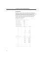
get-ip
Displays the switch’s current IP address:
SYS_console> get-ip
The device IP address is: 192.001.001.064
SYS_console> _
If the switch doesn’t have an IP address assigned:
SYS_console> get-ip
The device has no IP address defined.
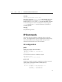
get-ip-conf
Displays the complete current IP configuration: IP address, netmask
(subnet mask), and broadcast address (default gateway).
SYS_console> get-ip-conf
The device IP address, netmask and broadcast are:
IP address
: 192.001.001.064
IP netmask
: 255.255.255.000
IP broadcast : 192.001.001.255
43
C H A P T E R
3
Intel Express 10/100 Fast Ethernet Switch
set-ip
set-ip <IPaddress>
Sets the IP address of the switch (technically, the switch’s SNMP
agent). If no IP address was previously set (default configuration), the
new value is saved in NVRAM and used immediately. Otherwise, the
new value is stored in NVRAM, but you must use the warm-reset
command or cycle the power for changes to take effect.
set-ip 192.001.001.064
Device IP Address unchanged for this session
Device IP Address change in the NVRAM OK
The device NVRAM IP address will be:
IP address
: 192.001.001.064
set-ip-conf
set-ip-conf <IPaddress> <netmask> <broadcast>
Sets the IP address, netmask (subnet mask), and broadcast IP address.
If no IP configuration was previously set (default configuration), the
new values are saved in NVRAM and used immediately. Otherwise,
the new values are stored in NVRAM, but you must use the
warm-reset command or cycle the power for changes to take effect.
SYS_console> set-ip-conf 192.1.1.64 255.255.255.0 192.1.1.255
Device IP Address set for this session
Device IP Address change in the NVRAM OK
The device IP configuration in the next session will be:
IP address
: 192.001.001.064
IP netmask
: 255.255.255.000
IP broadcast : 192.001.001.255
get-bootp
Displays the current state of the BOOTP process. By default, BOOTP
is disabled.
set-bootp
set-bootp {enable|disable}
Enables or disables BOOTP. With BOOTP enabled, the switch looks
for a BOOTP server at startup if no IP configuration is defined.
get-slip
Displays the current SLIP address. By default, no SLIP address is
assigned.
44
C H A P T E R
3
Console Command Reference
get-slip-conf
Displays the current SLIP configuration.
set-slip
set-slip <IPaddress>
Sets the SLIP address, which can’t be the same as the IP address.
set-slip-conf
set-slip-conf <IPaddress> <netmask> <broadcast>
Sets the SLIP configuration. The arguments are the same as
set-ip-conf.
get-gatew
Displays the default gateway. Use this default router when accessing a
different IP network.
set-gatew
set-gatew <IPaddress>
Sets the default gateway IP address, which specifies the router used to
access a different IP network. The default value for this setting is
0.0.0.0 (no gateway). You can also set the default gateway using the
set-ip-conf command.
SYS_console> set-gatew 192.1.1.255
Device Default Gateway change in the NVRAM OK
Device Default Gateway changed to : 192.1.1.255
SYS_console> get-gatew
Device default gateway address is: 192.001.001.255
get-def-ttl
Displays the default IP time-to-live (TTL) value. This value (from 1
to 255) is the number of routers a frame can go through before being
dropped. The default is 255.
set-def-ttl
set-def-ttl <number>
Modifies the default TTL value, from 1 to 255 router hops allowed.
45
C H A P T E R
3
Intel Express 10/100 Fast Ethernet Switch
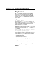
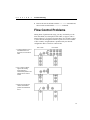
Ping Commands
The ping command sends an Internet Control Message Protocol
(ICMP) echo request packet to a station. The ping process is
asynchronous, so any responses are mixed in with other system
console messages. For this reason, it’s best to avoid typing other
commands (except ping-stop, which cancels the ping) while the
process is active.
ping
ping <IPaddress> {<number>|0}
You can ping a device (at IP address) a number of times or 0 for
endless ping. The ping process sends a number of datagrams, one per
second. One line of output appears for every response received.
Normal response time is 1 to 10 seconds.
The ping command tests the connectivity between the switch and an
IP station. It is not intended as a traffic generator, so it’s best to avoid
using an endless ping. To stop the ping, use cC or enter the pingstop command.
SYS_console> ping 192.1.1.1 10
129.001.001.001 Alive. echo reply: id 297, seq 4, echo-data-len 8
PING process stopped - press <CR> for prompt
— press <CR> to get the prompt again
If the IP station doesn’t respond, the console prompt appears and no
output is added. Failure to get an echo response from an IP station
may be due to the following:
•
A bad physical connection.
•
A nonexistent or inactive IP station.
•
Network unreachable: no corresponding entry in the routing table.
•
Destination unreachable: the default gateway failed to route the
datagram.
•
Outdated Address Resolution Protocol (ARP) table information.
Clear the ARP table with the del-arp-entry command.
If there’s an active ping process due to a previous “long” ping
command and you try to start a new ping, the command fails.
ping-stop
Stops the active ping process. You can also press cC.
46
C H A P T E R
3
Console Command Reference
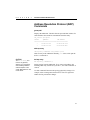
Address Resolution Protocol (ARP)
Commands
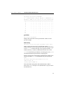
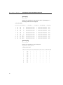
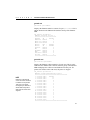
get-arp-tbl
Displays the ARP table. The table lists the port and MAC address for
each IP address the switch has communicated with recently.
SYS_console> get-arp-tbl
IfIndex
IpAddress
MAC Address
====================================================
1
129.001.001.001
00-40-05-2D-73-9C
1
129.001.001.200
00-02-A0-D4-9A-57
add-arp-entry
add-arp-entry <IPaddress> <mac_address> <port>
Adds an entry to the ARP table manually. port is the switch port the
device is connected to.
CAUTION
The del-lt-entry command is very powerful,
allowing you to change the
entire switching database
with the exception of the
system MAC addresses. Use
it with caution.
del-arp-entry
del-arp-entry {<IPaddress>|*}
Deletes entries from the ARP table. If you enter an IP address, the
matching ARP entry is deleted. If you enter *, the entire ARP table is
cleared.
Use this command if the network topology physically changes. For
example, when a management station moves from one segment to
another and its port number changes.
47
C H A P T E R
3
Intel Express 10/100 Fast Ethernet Switch
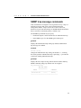
SNMP Commands
Use these commands to configure the SNMP agent itself — access
and trap configuration.
SNMP community strings
SNMP community strings authenticate access to the Management
Information Base (MIB). Community strings function as “passwords”
embedded in every SNMP packet. The community string must match
a community strings configured in the switch before the message can
be processed. There are two community strings, one for the two types
of access:
•
read
•
write
mode permits read access to all the objects in the MIB, but
doesn’t allow write access.
mode permits read and write access to all objects in the
MIB.
get-comm
get-comm {read|write|*}
Displays the SNMP community string for a given access mode (read
or write). If the access mode is specified as *, both read and write
community strings are displayed.
SYS_console> get-comm *
Current read community is: < public >
Current write community is: < private >
set-comm
set-comm {read|write} <community-string>
Specifies the SNMP community string for either of the two access
modes (read and write).
SYS_console> set-comm write password
New write community is: < password >
48
C H A P T E R
3
Console Command Reference
SNMP trap message commands
If the switch detects an irregular event, it generates a trap. A trap is a
notification message that can be sent to predefined network
management stations. A trap event can be a cold or warm reset,
detection of a port link status change, an SNMP authentication failure
due to an incorrect community string, or similar event.
The SNMP trap commands let you specify
•
whether the Express 10/100 Switch issues an authentication trap.
•
which NMSs (up to five) the SNMP agent sends traps to.
get-auth
Displays the authentication trap setting. By default, authentication
trap messages are enabled.
set-auth
set-auth {on|off}
Changes the authentication trap setting. The default is on, meaning
the switch generates authentication traps. Specifying off prevents the
switch from sending authentication traps.
get-traps
Displays the list of trap-receiving stations (their IP address and trap
SNMP community string). By default, none are assigned.
SYS_console>get-traps
SNMP TRAP TABLE
===============
IPADDR
COMMUNITY
---------------------------------------------192.168.001.065
-----testing
----------------------------------------------
49
C H A P T E R
3
Intel Express 10/100 Fast Ethernet Switch
add-trap
add-trap <IPaddress> <trap-community>
Enters the IP address of the receiving station and the trap community
string that appears in the trap message. The trap table can contain up
to five receiving stations.
SYS_console> add-trap 129.1.1.76 engineering
Entry 129.1.1.76 - rnd added
SNMP TRAP TABLE
===============
IPADDR
COMMUNITY
----------------------------------------------129.001.001.065
----------public
129.001.001.007
----------trapcomm
129.001.001.076
----------engineering
-----------------------------------------------
del-trap
del-trap <IPaddress>
Removes a station from the trap table.
SYS_console> del-trap 129.1.1.7
Entry 129.1.1.7 - trap comm deleted
Switching Database
Commands
Use the commands listed in this section to manage the switching
database.
The switching database is also called a learn table or address table.
Each active entry contains the information relevant to a network node,
identified by its Ethernet MAC address. Each entry contains the
following information:
Lock. If locked (denoted as a +), the entry is static and isn’t deleted
by the switch aging process. If unlocked (denoted as a -), the entry is
dynamic and is automatically deleted if the workstation is not active
during the aging time period.
50
C H A P T E R
3
Console Command Reference
Self (not user configurable). If on (denoted as a +), the entry is a
system address. These are the switch’s individual and group
addresses, as well as other addresses added by the management
system. If off (denoted as a -), the entry contains the MAC address of
a station on the network.
Dport. The destination port where frames from the MAC address are
forwarded. This doesn’t apply if the MAC address has a custom filter
applied to it.
Mgmt. If on (denoted as a +), frames from the entry are sent to the
management port on the switch.
The first section, “Database control commands,” lists commands
relevant to standard MAC addresses (for example, determining the
behavior of the switch when it sees a particular address). The second
section, “Custom filtering,” lists commands pertinent to the custom
filtering capabilities of the switch.
Database control commands
get-lt-entry
get-lt-entry <index>
Displays entry number index in the switching database. The index
range is 1 to 4096.
SYS_console>get-lt-entry 19
Entry
—— MAC Address ——
LOCK
SELF
DPORT
MGMT
==============================================================
19
00-20-C5-00-59-E6
5
-
The entry has these properties:
•
The entry number is 19.
•
The MAC address is 00-20-C5-00-59-E6.
•
The entry is dynamic and will be aged out (lock is off).
•
It’s not a system address (self is off).
•
Frames are forwarded to port 5 only.
•
Frames are not forwarded to the management port (mgmt is off).
51
C H A P T E R
3
Intel Express 10/100 Fast Ethernet Switch
get-lt-16
get-lt-16 {<index>|*}
Displays 16 switching database entries starting at index (or * to
continue from the last displayed index).
NOTE
In the example, entries 10-17
are system entries and can’t
be deleted or modified.
Entries 18 and up are
automatically learned MAC
addresses, as indicated by
lock = OFF (-) and by
self = OFF (-).
SYS_console>get-lt-16 10
Entry —— MAC Address ——
LOCK
SELF
DPORT
MGMT
==============================================================
10
00-20-1A-20-20-D9
+
+
-CUSTOM FILTER11
00-20-1A-24-20-D9
+
+
-CUSTOM FILTER12
00-20-1A-28-20-D9
+
+
-CUSTOM FILTER13
00-20-1A-2C-20-D9
+
+
-CUSTOM FILTER14
00-20-1A-30-20-D9
+
+
-CUSTOM FILTER15
00-20-1A-34-20-D9
+
+
-CUSTOM FILTER16
00-20-1A-38-20-D9
+
+
-CUSTOM FILTER17
FF-FF-FF-FF-FF-FF
+
-CUSTOM FILTER18
00-40-05-2D-9D-49
3
19
00-20-C5-00-59-E6
4
20
00-00-92-94-01-54
1
21
00-C0-1D-01-06-20
1
22
00-40-05-2B-0A-26
5
23
00-40-05-29-1E-DE
7
24
00-40-05-2B-17-37
4
25
08-00-20-76-72-89
2
-
SYS_console>get-lt-16 *
Entry —— MAC Address ——
LOCK
SELF
DPORT
MGMT
==============================================================
26
00-40-05-11-06-AD
2
27
00-40-05-2B-59-EA
3
28
00-40-05-2D-99-3A
7
29
00-40-05-16-80-7C
5
30
00-00-C0-60-A7-B9
5
31
00-40-05-1A-A1-69
5
32
00-40-05-29-1E-EB
6
33
00-40-05-2E-DF-15
5
34
00-40-05-28-B4-1A
7
35
00-40-05-2F-93-A7
4
36
00-40-33-32-A6-58
6
37
00-40-05-15-70-5E
5
38
00-40-05-1A-A1-5F
1
39
00-40-05-28-B7-2A
5
40
00-40-05-2B-16-3D
2
41
00-40-05-15-B6-83
4
-
52
C H A P T E R
3
Console Command Reference
find-lt-addr
find-lt-addr <mac_address>
Searches for a MAC address in the switching database and displays its
description, if found.
SYS_console>find-lt-addr 00-40-05-2B-16-3D
Entry
---- MAC Address ----
LOCK
SELF
DPORT
MGMT
==============================================================
40
00-40-05-2B-16-3D
-
-
3
-
del-lt-entry
del-lt-entry <index>
Deletes the specified switching database entry, using the entry number
from the get-lt-16 command. If that entry number is not active, the
command has no effect. You can’t delete entries with the self field set
(system addresses).
SYS_console> del-lt-entry 15
Deleting entry at index - 15 -
OK
del-lt-addr
del-lt-addr <mac_address>
Deletes the switching database entry that matches the specified MAC
address.
SYS_console> del-lt-addr 00-40-05-2b-59-4c
Deleting entry with MAC address - 00-40-05-2b-59-4c OK
The command fails if the MAC address isn’t found in the switching
database.
add-lt-entry
add-lt-entry <mac_address> {lock-off|lock-on} <dport>
Add an entry to the switching database. The lock setting is described
at the beginning of this section. dport is the destination port number.
add-lt-entry 00-A0-C9-00-11-11 lock-off 3
This example sends packets from the device with MAC address
00-A0-C9-00-11-11 to port 3. lock-off means the entry is deleted if
the device is inactive for 300 seconds (the default aging time).
53
C H A P T E R
3
Intel Express 10/100 Fast Ethernet Switch
get-lt-age
Displays the switching database aging time in seconds. This is the
amount of time the switch stores a device’s MAC address before
clearing it from the database. An entry whose MAC address doesn’t
appear in the source field of an incoming packet for this period of
time is discarded. The default is 300 seconds.
SYS_console> get-lt-age
The running aging time is: 300 seconds
set-lt-age
set-lt-age {run|nvram|all} <aging_time>
Modifies the switching database aging time.
The aging_time is in seconds with a default of 300 seconds and a
range of 10 to 11,000 seconds. Decrease the time if the number of
active workstations is larger than 1024.
SYS_console> set-lt-age run 280
Aging Period update in the running database OK
SYS_console> set-lt-age all 100
Aging Period update in NVRAM OK
Aging Period update in the running database OK
Custom filtering
Use custom filters to ensure a device can reach other devices
regardless of where the device is attached. For example, if you have a
laptop computer that acts as a management station, you want to make
sure you can reach your servers from anywhere on the network, even
from segments that have security VLAN restrictions.
The custom filter entry for an address displays onscreen as a matrix.
The source (SRC) column lists the available source ports (1 through
12, where ports 9 through 12 are for optional expansion modules
which may not be installed). The other columns each represent an
available destination port. A + represents a forwarding path. In the
following example, each source port forwards frames to port 5. (A +
isn’t listed in the P5 column because ports don’t forward frames to
themselves.)
54
C H A P T E R
3
Console Command Reference
SYS_console> get-lt-filter 00aa00a5898b
12
00-AA-00-A5-89-8B
SRC PORT to : MGMT
P1
LOCK_OFF
P2
P3
P4
SELF_OFF --- VIRTUAL LAN ----P5
P6
P7 P8
P9 P10 P11 P12
================================================================
1
+
2
+
3
+
4
+
5
6
+
7
+
8
+
9
+
10
+
11
+
12
+
-
get-lt-filter
get-lt-filter <mac_address>
Displays the custom filter for the specified MAC address. See the
previous example.
add-cf-entry
add-cf-entry {lock-on|lock-off|perm} <mac_address> <sport> <dport>
Adds a custom filter entry for the specified MAC address. lock-on
indicates the entry won’t be aged out, but will be lost when the switch
is reset. lock-off indicates the entry can be aged out normally. perm
indicates the entry is written to NVRAM and remains after a reset.
is a hexadecimal representation of incoming ports, and dport is
a hexadecimal bitmask representation of outgoing ports.
sport
Packets arriving at the switch with the destination MAC address from
any port specified in sport are transmitted to all ports specified in
dport.
SYS_console> add-cf-entry perm 00-AA-00-11-11-11 C C0
Add CF LT entry
OK
CF Entry Update in NVRAM
OK
This custom filter sends packets with destination MAC address
00-AA-00-11-11-11 from port 3 or 4 (hexadecimal C) to ports 6 and 7
(hexadecimal C0).
55
C H A P T E R
3
Intel Express 10/100 Fast Ethernet Switch
del-cf-entry
del-cf-entry {run|nvram} <mac_address> <sport>
Deletes the custom filter entry for address mac_address from source
port sport. Ports are deleted one at a time by entering the port
number. Select run to delete the entry from the currently running
table only. Select nvram to remove the entry from the NVRAM as
well as the currently running table.
get-nv-cftbl
Displays the custom filter table stored in NVRAM.
NVRAM CUSTOM FILTERS TABLE
==============================
Entry ---- MAC Address --------------------------------1
00-00-00-11-11-11
get-nv-cfilt
get-nv-cfilt <mac_address>
Displays the custom filter associated with mac_address from the
custom filter table stored in NVRAM.
VLAN Commands
Use VLANs to limit the broadcast domain and establish security
virtual LANs. For procedural information on VLANs, see page 23.
56
•
run
•
nvram
•
all
indicates that only the currently running configuration is
changed. A reset doesn’t restore the changes.
indicates that only the configuration stored in NVRAM is
changed. Changes don’t take effect until a reset.
indicates that both the currently running configuration and the
NVRAM configuration is changed. Changes take effect
immediately and are restored after a reset.
C H A P T E R
3
Console Command Reference
get-con-matrix
Displays the current connectivity matrix for the switch. The first
column is the source port. The other columns are destinations where
frames from a given source port can be forwarded. Unlearned
addresses (addresses that aren’t in the switching database) are
forwarded to all ports marked with a + in the source port’s row.
Learned addresses are forwarded to their destinations only if the
destination is marked with a + in the source port’s row. Ports don’t
need to be forwarded to themselves.
SYS_console> get-con-matrix
VLAN CONNECTIVITY MATRIX
==========================
SRC PORT to : P1 P2 P3 P4 P5 P6 P7 P8 P9 P10 P11 P12
================================================================
1
+
+
+
+
+
+
+
2
+
+
+
+
+
+
+
3
+
+
+
+
+
+
+
4
+
+
+
+
+
+
+
5
+
+
+
+
+
+
+
6
+
+
+
+
+
+
+
7
+
+
+
+
+
+
+
8
+
+
+
+
+
+
+
9
10
11
12
-
get-vbc-matrix
Displays the current broadcast domain matrix for the switch. See the
get-con-matrix command above for a description of the resulting
table. Here, only the broadcast address is affected.
SYS_console> get-vbc-matrix
VBC CONNECTIVITY MATRIX
==========================
SRC PORT to : P1 P2 P3 P4 P5 P6 P7 P8 P9 P10 P11 P12
===============================================================
1
+
+
+
+
+
+
+
2
+
+
+
+
+
+
+
3
+
+
+
+
+
+
+
4
+
+
+
+
+
+
+
5
+
+
+
+
+
+
+
6
+
+
+
+
+
+
+
7
+
+
+
+
+
+
+
8
+
+
+
+
+
+
+
9
10
11
12
-
57
C H A P T E R
3
Intel Express 10/100 Fast Ethernet Switch
set-vbc-domain
set-vbc-domain {run|nvram|all} <port_list>
Establishes a virtual broadcast domain (VBD). port_list is a list of
ports, separated by dashes, to group into a broadcast domain.
set-vbc-domain all 2-5-6-7
This creates a VBD of ports 2, 5, 6, and 7.
del-vbc-domain
del-vbc-domain {run|nvram} <domain_id>
Deletes a virtual broadcast domain. Use the get-vbc-tbl command to
see a list of domain ID numbers.
get-vbc-tbl
get-vbc-tbl {run|nvram}
Displays the list of defined virtual broadcast domains.
SYS_console> get-vbc-tbl run
RUNTIME
VIRTUAL BROADCAST DOMAIN TABLE
===========================================
VBC ID
P1 P2 P3 P4 P5 P6 P7 P8 P9 P10 P11 P12
===========================================================
1:
+
+
+
+
-
set-sec-vlan
set-sec-vlan {run|nvram|all} <port_list>
Establishes a Security Virtual LAN (SVLAN). Arguments are
identical to set-vbc-domain. Ports in an SVLAN can exchange data
only with other ports in the same SVLAN.
del-sec-vlan
del-sec-vlan {run|nvram} <lan_id>
Deletes the SVLAN specified by lan_id. Use the get-svlan-tbl
command to see these ID numbers.
58
C H A P T E R
3
Console Command Reference
get-svlan-tbl
get-svlan-tbl {run|nvram}
Displays the table of defined SVLANs.
SYS_console> get-svlan-tbl run
RUNTIME
SECURITY VIRTUAL LANs TABLE
================================
SVLAN ID
P1 P2 P3 P4 P5 P6 P7 P8 P9 P10 P11 P12
===========================================================
1:
+
+
+
2:
+
+
+
-
In this example, ports 1, 2, and 3 are an SVLAN and ports 1, 2, and 5
are an SVLAN. This means that ports 1 and 2 can talk to each other
and to ports 3 and 5, but 3 and 5 can’t talk to each other.
set-mon-port
set-mon-port <port>
Sets the port to be monitored. port is the port number. All traffic
from this port is duplicated, or mirrored, on the port specified by the
monitor command.
monitor
monitor <port>
Sets the monitoring port. All traffic from the port specified by
set-mon-port is duplicated on port.
stop-mon
Stops port monitoring.
59
C H A P T E R
3
Intel Express 10/100 Fast Ethernet Switch
Spanning Tree Commands
Spanning tree automatically configures a loop-free topology in a
bridged environment. The spanning tree agent is implemented in
conformance with the IEEE 802.1d standard. In most cases, the
defaults work fine and you won’t need to change any parameters.
Example
Spanning tree is enabled anytime a packet could potentially be caught
in an infinite loop on the network.
Spanning tree disables
this port to prevent a
redundant loop.
The protocol uses the port with the most efficient path and turns off
the other port. In the example, each hub is connected to switch and to
each other. Consequently, the workstation has two paths to the switch.
In Ethernet, this isn’t allowed and one of the switch ports must be
turned off. Spanning tree sends out configuration messages and
automatically determines which port is turned off. However, by
changing spanning tree parameters, you can manually determine
which port is turned off.
Spanning tree determines which port is turned off by selecting the
port with the lowest cost path. This port is then called the root bridge
(in this case, the root bridge is a switch port). Think of the lowest cost
path as the quickest route from the workstation to the switch. In the
case of a tie, the lowest numbered switch port is the root bridge. In the
example, port 2 is root bridge and port 8 is turned off.
60
C H A P T E R
3
Console Command Reference
get-stp
get-stp
Displays the current state of spanning tree (either enabled or
disabled). By default, spanning tree is enabled in accordance with
802.1d.
SYS_console> get-stp
Running Spanning Tree engine is enabled
Next session the Spanning Tree engine will be enabled
set-stp
set-stp {enable|disable}
Enables or disables the spanning tree protocol. Enabled is the default.
Enabling or disabling spanning tree doesn’t take effect until the
SNMP agent is reset (warm-reset, cold-reset, or turning the power
off and then on again).
get-st-bcfg
get-st-bcfg
Displays the spanning tree bridge parameters. If spanning tree is
disabled, parameters aren’t displayed.
SYS_console> get-st-bcfg
802.1D SPANNING TREE BRIDGE INFO
==================================
Designated Root
: 8000-0020-1a00-0a5b
Bridge Priority
: 32768
Root Cost
:
0
Root Port
:
0
Max Age
:
20
Hello Time
:
2
Hold Time
:
1
Forward Delay
:
15
Bridge Max Age
:
20
Bridge Hello Time
:
2
Bridge Forward Delay :
15
61
C H A P T E R
3
Intel Express 10/100 Fast Ethernet Switch
get-st-pcfg
get-st-pcfg
Displays the spanning tree port parameter table. If spanning tree is
disabled, parameters aren’t displayed.
STP PORT TABLE
================
ID Prior State PathCost
DesigRoot
DesigCost
DesigBridge
DesigPort
------------------------------------------------------------------------------1 128
fwd
10
8000-0020-1a00-0a5b
0
8000-0020-1a00-0a5b
8001
2 128
fwd
10
8000-0020-1a00-0a5b
0
8000-0020-1a00-0a5b
8002
3 128
fwd
10
8000-0020-1a00-0a5b
0
8000-0020-1a00-0a5b
8003
4 128
fwd
10
8000-0020-1a00-0a5b
0
8000-0020-1a00-0a5b
8004
5 128
fwd
10
8000-0020-1a00-0a5b
0
8000-0020-1a00-0a5b
8005
6 128
fwd
10
8000-0020-1a00-0a5b
0
8000-0020-1a00-0a5b
8006
7 128
fwd
10
8000-0020-1a00-0a5b
0
8000-0020-1a00-0a5b
8007
8 128
fwd
10
8000-0020-1a00-0a5b
0
8000-0020-1a00-0a5b
8008
9 128
dis 65535
8000-0020-1a00-0a5b
0
8000-0020-1a00-0a5b
8009
10 128
dis 65535
8000-0020-1a00-0a5b
0
8000-0020-1a00-0a5b
800a
11 128
dis 65535
8000-0020-1a00-0a5b
0
8000-0020-1a00-0a5b
800b
12 128
dis 65535
8000-0020-1a00-0a5b
0
8000-0020-1a00-0a5b
800c
get-st-syscfg
get-st-syscfg
Displays the spanning tree state for all ports.
SYS_console> get-st-syscfg
SYSTEM PORTS STATE
==================
PORT_ID STATE ST_RCV ST_XMT MG_RCV MG_XMT OP_RCV OP_XMT LRN_ENB
---------------------------------------------------------------1
fwd
+
+
+
+
+
+
+
2
fwd
+
+
+
+
+
+
+
3
fwd
+
+
+
+
+
+
+
4
fwd
+
+
+
+
+
+
+
5
fwd
+
+
+
+
+
+
+
6
fwd
+
+
+
+
+
+
+
7
fwd
+
+
+
+
+
+
+
8
fwd
+
+
+
+
+
+
+
9
dis
10
dis
11
dis
12
dis
-
62
C H A P T E R
3
Console Command Reference
set-br-prio
set-br-prio <priority>
Sets the spanning tree bridge priority. Bridge priority forces a bridge
to be selected as the root bridge, or as a designated bridge. The bridge
priority is a value used in determining the identity of the root bridge.
The bridge with the lowest value has the highest priority and will be
selected as the root.
is a number from 0 to 65535. This is equivalent to setting
the MIB variable dot1dStpPriority (RFC 1493).
priority
set-br-maxage
set-br-maxage <maxage>
Sets the spanning tree bridge maximum age. Max age is the maximum
time in seconds a bridge waits without receiving spanning tree
configuration messages before attempting a reconfiguration. This
parameter takes effect when a bridge is operating as the root bridge.
Bridges not acting as the root use the root bridge’s Max Age
parameter.
is in seconds, from 6 to 40. However, the corresponding MIB
variable, dot1dStpBridgeMaxAge (RFC 1493), is in hundreths of
seconds, ranging from 600 to 4000, and must be a multiple of 100.
maxage
set-br-hellot
set-br-hellot <hello_time>
Sets the spanning tree bridge hello time. Hello time is the interval
between transmission of spanning tree configuration messages in
seconds. All bridges send configuration messages during
reconfiguration to select the designated root bridge (in this case, the
switch port). Ports not acting as a root bridge use the root bridge
hello-time value. After this is determined, only designated bridges
(ports) send configuration messages.
is a number from 1 to 10 in seconds. However, the
corresponding MIB variable, dot1dStpBridgeHelloTime (RFC 1493),
is in hundreths of seconds ranging from 100 to 1000, and must be a
multiple of 100.
hello_time
63
C H A P T E R
3
Intel Express 10/100 Fast Ethernet Switch
set-br-fwdel
set-br-fwdel <forward_delay>
Sets the spanning tree bridge forward delay. Forward delay is the time
interval in seconds spent waiting to change a port from its spanning
tree preforwarding state to a forwarding state. This is necessary
because every bridge on the network should ensure no loop is formed
before allowing the port to forward packets.
is in seconds, from 4 to 30. However, the
corresponding MIB variable, dot1dStpBridgeForwardDelay (RFC
1493), is in hundreths of seconds from 400 to 3000, and must be a
multiple of 100.
forward_delay
set-prt-prio
set-prt-prio <port_number> <port_priority>
Sets the spanning tree port priority. port_number is the decimal port
number, and port_priority is a number from 1 to 255. This is
equivalent to setting the MIB variable dot1dStpPortPriority
(RFC 1493).
set-prt-enb
set-prt-enb <port_number> {enable|disable}
Enables or disables a port in the spanning tree. port_number is the
decimal port number. This is equivalent to setting the MIB variable
dot1dStpPortEnable (RFC 1493).
set-prt-pcost
set-prt-pcost <port_number> <path_cost>
Sets the spanning tree port path cost. port_number is the decimal port
number, and path_cost is path cost from 1 to 65535. This is
equivalent to setting the MIB variable dot1dStpPortPathCost
(RFC 1493).
64
C H A P T E R
3
Console Command Reference
Port Configuration Commands
Use these commands to configure and display port settings.
get-port-cfg
Displays the current port configuration.
SYS_console> get-port-cfg
PORT_ID LAN_TYPE LINK IF_TYPE SPEED_SEL LAN_SPEED
FDPLX FCTRL
======================================================================
1
ETH10/100 OFF
TPFD
ASENSE
10Mbps
OFF
ON
2
ETH10/100 OFF
TPFD
ASENSE
10Mbps
OFF
ON
3
ETH10/100 OFF
TPFD
ASENSE
10Mbps
OFF
ON
4
ETH10/100 OFF
TPFD
ASENSE
10Mbps
OFF
ON
5
ETH10/100 ON
TPFD
ASENSE
10Mbps
OFF
ON
6
ETH10/100 OFF
TPFD
ASENSE
10Mbps
OFF
ON
7
ETH10/100 OFF
TPFD
ASENSE
10Mbps
OFF
ON
8
ETH10/100 OFF
TPFD
ASENSE
10Mbps
OFF
ON
9
NONE
---- PORT NOT INSTALLED ---10
NONE
---- PORT NOT INSTALLED ---11
NONE
---- PORT NOT INSTALLED ---12
NONE
---- PORT NOT INSTALLED ----
The command displays the following information for each port:
•
LAN type: ETH10/100 indicates the port can operate at
10 or 100 Mbps.
•
Link status: ON or OFF.
•
Physical interface type: TPFD indicates Twisted-pair (TP)
Ethernet, Full Duplex (FD) capable.
•
Speed select: ASENSE indicates the port auto-negotiates with the
device on the other end.
•
LAN Speed: LAN_SPEED indicates the speed of the link. By
default, all ports are 10 Mbps when no device is attached.
•
Full duplex mode: ON or OFF (default).
•
Flow control: ON (default) or OFF. If you set a port to full duplex,
flow control is automatically turned off (changes take effect after
a reset). If you try to set flow control to ON while full duplex is
selected, the Console Manager ignores the change on reset.
NOTE
Setting a port to full duplex
automatically disables flow
control. Since collisions don’t
happen on a full-duplex link,
flow control isn’t possible.
One exception is between two
Express 10/100 switches. A
special piece of information is
added to packets traveling
between switches to accomplish this.
65
C H A P T E R
3
Intel Express 10/100 Fast Ethernet Switch
set-port-dplex
set-port-dplex <port_number> {half|full}
Specifies whether the given port is in full-duplex or half-duplex
(standard Ethernet) mode. The default is half-duplex. You must set
the port speed to either 10 or 100 (asense is the default) before setting
a port to full-duplex.
SYS_console> set-port-dplex 2 full
Port configured in <full_duplex> mode
Parameter change in NVRAM OK
set-speed-sel
set-speed-sel <port-number> {asense|10|100}
Sets a port’s speed to 10, 100, or auto detect. The default is asense.
set-port-fctrl
set-port-fctrl <port-number> {on|off}
Turns the flow control feature on or off for the specified port. The
default is on.
If the port is in full-duplex mode, flow control is turned off. Flow
control or full duplex (or neither) can be active, but not both. One
exception is between two Express 10/100 Switches.
SYS_console> set-port-fctrl 2 off
Port 2 - flow control <off>
Parameter change in NVRAM OK
Statistics Commands
This section contains instructions for displaying switching statistics
using the Console Manager. The following commands provide full
physical layer information as well as inter-port switching statistics.
See Chapter 2 for definitions of individual statistics.
Under heavy traffic loading conditions, the Console Manager may
understate the Ethernet statistical counts. You can also use a protocol
analyzer to monitor the segment the port is attached to. See step 8 on
page 72 for configuration details.
clr-cnt
Clears (resets) the Ethernet and bridging statistical counters.
66
C H A P T E R
3
Console Command Reference
get-eth-cnt
get-eth-cnt <port-number>
Displays the Ethernet Statistics Counters for port port-number. This is
almost identical to the Ethernet-like Statistics Group of the Ethernet
MIB.
SYS_console> get-eth-cnt 1
Ethernet Statistics for port 1
=================================
Transmit
OK
:
2817886
Underflow
Errors:
0
Exces Coll Errors:
0
Exces Fctrl Errors:
0
Receive
EOF
:
2896502
Receive
OK
:
2896498
Overflow
Errors:
0
CRC
Errors:
0
Alignment
Errors:
0
Runt
Errors:
4
Lost/Fctrl Errors:
0
Too Long
Errors:
0
=================================
get-colls-cnt
get-colls-cnt <port-number>
Displays the Ethernet collision statistics for each port. This is nearly
identical to the Ethernet-like collisions statistics group of the Ethernet
MIB and displays the collision count distribution for this port. If a
packet still collides on the 16th count, the packet is dropped.
NOTE
Collisions on the first few
counts are normal. However,
if collisions occur past the
10th count, you should
reconfigure your network so
devices that mostly talk to
each other are on the same
segment.
SYS_console> get-colls-cnt 1
Ethernet Collision Distribution for port 1
==================================================
0 collison count :
2819392
1 collison count :
10
2 collison count :
13
3 collison count :
4
4 collison count :
3
5 collison count :
2
6 collison count :
0
7 collison count :
2
8 collison count :
2
9 collison count :
0
10 collison count :
0
11 collison count :
0
12 collison count :
0
13 collison count :
0
14 collison count :
0
15 collison count :
0
16 collison count :
0
==================================================
67
C H A P T E R
3
Intel Express 10/100 Fast Ethernet Switch
get-rmon-cnt
get-rmon-cnt <port>
Displays the remote monitoring (RMON) statistics group 1 counters
for port.
SYS_console> get-rmon-cnt 1
Ethernet RMON Counters for port 1
====================================================
etherStatsOctets
: 942514513
etherStatsPkts
:
2900281
etherStatsBcastPkts
:
0
etherStatsMcastPkts
:
0
etherStatsCRCAllignPkts:
0
etherStatsUndersizePkts:
0
etherStatsOversizePkts :
0
etherStatsRuntPkts
:
4
etherStatsJabberPkts
:
0
etherStatsCollisions
:
36
get-sdist-cnt
get-sdist-cnt <port>
Displays the RMON statistics packet size histogram for port.
SYS_console> get-sdist-cnt 1
RMON Packet Size Distribution Counters for port 1
============================================================
etherStatsPkts64Octets
:
678664
etherStatsPkts65to127Octets
:
1634637
etherStatsPkts128to255Octets
:
42062
etherStatsPkts256to511Octets
:
27590
etherStatsPkts512to1023Octets :
49248
etherStatsPkts1024to1518Octets :
470762
get-br-cnt
get-br-cnt <port-number>
Displays the switching statistics counters for a port. The command
displays the number of:
68
•
frames or bytes received.
•
frames forwarded.
•
multicast frames.
•
frames with unknown destination and subsequently multicast.
•
frames transmitted.
C H A P T E R
3
Console Command Reference
•
packets lost (if flow control is disabled) or number of packets
retransmitted by the originator due to flow control (if flow control
is enabled).
•
packets or bytes forwarded to each port. For the port you
specified, the number of packets or bytes represents filtered
frames. Filtered frames are ones that don’t need to be forwarded
because they’re destined for the same port they came in on.
SYS_console> get-br-cnt 1
Ethernet Switching Counters for port 1
====================================================
Frm
Received OK :
2905033
Bytes Received
: 943372029
Frm Filtered
:
0
Frm to all ports :
0
Frm multicast
:
0
Frm lost/fctrl
:
0
Transmit OK
:
2826591
Forward to port
:
FRAMES
BYTES
----------------------------------------------------1
:
0
0
2
:
0
0
3
:
0
0
4
:
0
0
5
:
0
0
6
:
0
0
7
:
0
0
8
:
2905013
943375393
9
:
0
0
10
:
0
0
11
:
0
0
12
:
0
0
====================================================
69
C H A P T E R
3
Intel Express 10/100 Fast Ethernet Switch
get-mgm-brcnt
Displays the counters for the management interface. Management
counters are continually updated even when no devices are attached to
the switch (this is why the port Xmt LEDs always blink). This
information is useful for seeing how much traffic the management
interface is generating compared to the rest of the switch. This
amount is usually insignificant.
SYS_console> get-mgm-brcnt
Management Port Counters
=============================================
Frm
Received
:
15506
Bytes Received
:
1691744
Frm
Filtered
:
15506
Frm Received Bcast:
15506
Frm Transmited
:
93264
Frm Transmit Ucast:
0
Frm Transmit Mcast:
93264
Frm Transmit Bcast:
0
Received from port:
FRAMES
BYTES
---------------------------------------------------1
:
0
0
2
:
0
0
3
:
0
0
4
:
0
0
5
:
165
17536
6
:
326
39314
7
:
0
0
8
:
15015
1634894
9
:
0
0
10
:
0
0
11
:
0
0
12
:
0
0
Transmit to port :
FRAMES
BYTES
----------------------------------------------------1
:
11658
699480
2
:
11658
699480
3
:
11658
699480
4
:
11658
699480
5
:
11658
699480
6
:
11658
699480
7
:
11658
699480
8
:
11658
699480
9
:
0
0
10
:
0
0
11
:
0
0
12
:
0
0
---------------------------------------------------
70
4
Troubleshooting
If you have problems with your Intel Express 10/100 Fast Ethernet
Switch, use this chapter to help identify the problem and find a
possible solution.
If you can’t find information in this chapter about the problem you’re
having, get the following information:
•
The serial number of the Express 10/100 Switch printed on the
back side of the switch.
•
The firmware revision number displayed by the Console Manager
sys-stat message.
•
The configuration of the equipment connected to the switch.
•
The sequence of events leading up to your problem.
•
Actions you have already taken.
If you call Intel Customer Support, you have 90 days of free support
after your first call. Thereafter, Intel offers several Intel Support
Service options. See the inside back cover for more information.
71
C H A P T E R
4
Intel Express 10/100 Fast Ethernet Switch
General Problems
If you’re having problems with the switch, follow the steps below:
72
1
Verify that your cables are wired correctly. This is the most
common problem. Use a UTP crossover cable to directly connect
to a repeater or another switch. Use straight-through cables when
connecting to servers or workstations. Try both the MDI and
MDI-X connectors on port 1 if you’re unsure of which cable to
use. See page 8 for more information.
2
Make sure the unit is plugged into a functioning AC outlet. Also,
make sure the voltage setting next to the switch’s power
receptacle is set correctly. In the United States, Canada, and Japan
the setting is 115. In most European and Asian countries, it’s 230.
3
Review the switch’s Link LEDs to ensure the ports you believe
should be functioning are properly configured and not disabled.
Also, review the Link LEDs of other devices to ensure the ports
that should be functioning are properly attached to the switch.
4
Make sure devices connected to the switch are operating at the
same speed as the switch port. Each switch port can be forced to
either 10 or 100 Mbps (although auto-detect is the default). Also,
other devices connected to the switch may be capable of operating
at 10 or 100 Mbps. See page 66 for information on setting speed.
5
If you configured a port for full duplex, make sure the device on
the other end is configured for full duplex and is capable of
transmitting in full duplex. Repeaters/hubs/concentrators can’t
operate in full duplex mode.
6
Make sure the equipment attached to the switch is properly
configured. If the Coll LED is on continuously (and you don’t
have full duplex configured), you may have an adapter problem.
7
Use the Console Manager to check the switch’s status. Use the
sys-stat command to check overall system status and
get-port-cfg to check the status of each port. To monitor traffic,
use the switching statistics commands (see page 25).
8
You can also use a protocol analyzer to check monitor statistics. If
the port is configured in half-duplex mode, place a hub between
the switch and the other device and attach the protocol analyzer to
the hub. If the port is configured in full-duplex mode, place a tap
between the device and switch and then attach a protocol analyzer
to the tap. Contact your network services supplier for information
on protocol analyzers and taps.
C H A P T E R
4
Troubleshooting
9
Restore the switch’s defaults with the init-nvram command and
then reset the switch with the cold-reset command.
Flow Control Problems
During times of peak network usage, you may occasionally see the
Flow LED blink (for a description of the LED, see page 6). This is
normal. However, if it stays lit for more than a few seconds at a time,
or if the network management software reports an excessive number
of flow controls, it might indicate a problem with your network
configuration. Here’s how flow control works:
Port 1 buffer
Port 2 buffer
1 Incoming packets on Port 1
are destined for Port 2.
However, Port 2’s buffer is
filled.
2 Port 1 sends a collision
signal to the sending
device, telling it to
retransmit the packets. This
allows Port 2 to clear its
buffers.
3 When Port 2’s buffer are
cleared, retransmitted
packets are forwarded to
Port 2.
73
C H A P T E R
4
Intel Express 10/100 Fast Ethernet Switch
A port’s Flow LED flashes whenever a received packet needs to be
forwarded to a port that already has too many packets queued. This
indicates a temporary overload situation on one port; the total traffic
to the port exceeds the amount its buffer can hold. This usually occurs
when there are several fast devices on different ports trying to access
a device across the switch (for example, 100 Mbps workstations
accessing a 10 Mbps server). If this occurs rarely, don’t do anything.
However, if it occurs often, identify the devices causing flow control
and move them to the same segment as the device they’re talking to.
When Ethernet bandwidth is temporarily insufficient for the traffic,
three actions are possible: drop packets, use flow control, or segment
the network. Buffering packets only works for a very short while. An
extended overload will eventually overflow buffers and cause dropped
packets. Flow control stops transmission on a port and forces devices
to resend packets, ensuring that packets aren’t lost. This is the most
reasonable solution, since it relies on Ethernet’s inherent collision
detection mechanism to relieve temporary overload.
Additionally, because it relies on collision detection, full duplex isn’t
possible when flow control is enabled. The exception is between two
Express 10/100 switches. A special piece of information added to
packets traveling between switches accomplishes this.
74
A
Technical Information
This chapter contains detailed information on default port and switch
configuration options, product specifications, and supported standards
for SNMP and MIB features.
Default Configuration
System
Internal software filename: flash12.hex
Database aging time: 300 seconds
SNMP:
Read community: public
Write community: private
Authentication mode: enable
Traps: none set
IP:
BOOTP: disabled
TTL: 255 (in range 1 to 255)
75
A p p e n d i x
A
Intel Express 10/100 Fast Ethernet Switch
Ports 1-8
Type:
10BASE-T/100BASE-TX (auto detecting),
twisted-pair Ethernet (TPE)
Duplex mode:
Half
Flow control:
On
Ports 9-12
Not installed (see Accessories on next page)
Console Manager
Communications parameters: 9600 baud, 8-N-1
Login name: None
Password: None
Prompt:
SYS_console>
Spanning tree
76
Spanning tree:
Enabled
Bridge priority:
32768 0-65535
Bridge max. age:
20
6.0-40.0 sec.
Bridge hello time:
2
1.0-10.0 sec.
Bridge forward delay: 15
4.0-30.0 sec.
Port priority:
128
0-255
Path cost:
100 (1000/LAN speed in Mbps). If a port is
linked at 100 Mbps, the path cost is 10.
A p p e n d i x
A
Technical Information
Specifications
Features
Buffer size: 64 Kbytes per port, 512 Kbytes total
Architecture: Store and forward for complete runt and error filtering
on all packets. Flow control prevents packet loss.
MAC addresses supported: 4096 entries
Switching database: Transparent, automatic self-learning at full wire
speed. Cache aging time manageable. Custom filtering by hardware
address and port.
Accessories
Two-port 100BASE-TX expansion module (Intel order code
ES101MATX)
Two-port 100BASE-FX expansion module (Intel order code
ES101MAFX)
Redundant power supply (RPS) connector. RPS must be purchased
separately.
LANDesk Network Manager (Intel order code EC100SNMP).
Network Manager is a Windows-based SNMP network management
system designed to manage Intel hubs and switches.
Network Management
In-band and out-of-band SNMP with MIB II, private MIB and out-ofband serial console support.
Status Indicators (per port)
Displays Link, Transmit, Receive, Full Duplex/Collision, Flow
Control, Speed (10 or 100 Mbps).
77
A p p e n d i x
A
Intel Express 10/100 Fast Ethernet Switch
General Indicators
Displays Management activity, SNMP presence, power supply status,
device failure detection.
Boot and Configuration
NVRAM configuration loaded on power up and fully downloadable.
Firmware local or remote downloadable. BOOTP supported.
Connector Interfaces
UTP/STP RJ-45 (MDI-X pin configuration; MDI or MDI-X for port 1)
RS232
SC fiber optic (on optional 100BASE-FX media adapter)
Maximum Cabling Distances
Switch to switch or switch to NIC:
Category 5 UTP: 328 feet (100 meters)
62.5/125µ multimode fiber: 1.2 miles (2 kilometers) at full duplex
1351 feet (412 meters) at half duplex
Switch to repeater:
Category 5 UTP: 328 feet (100 meters)
62.5/125µ multimode fiber: 525 feet (160 meters)
Standards Supported
10BASE-T
100BASE-TX, 100BASE-FX Fast Ethernet (IEEE 802.3u)
FDSE (Full Duplex Switched Ethernet)
Spanning Tree (IEEE 802.1d)
Internet Hosts (RFC1122/1123)
SMI (RFC1155)
SNMP (RFC 1157)
MIB (RFC1556)
MIB II (RFC 1213)
ENET MIB (RFC1398)
Bridge MIB (RFC1493)
RMON (RFC1757)
UDP/IP (RFC768/950/1071/791)
Mounting
Standard 19-inch rack, with mounting brackets
1-inch minimum clearance, sides and back
78
A p p e n d i x
A
Technical Information
Electrical Specifications
AC line frequency: 47Hz-63Hz
Fuse: 100-120V/4A 200-240V/2A
Power Cord Specifications
115 volt configuration:
Minimum type SJT (SVT) 18/3, rated 250 Volts AC, 10 Amps with a
maximum length of 15 feet. One end is terminated in an IEC 320
attachment plug, the other in a NEMA 5-15P plug.
230 volt configuration:
Minimum type SJT (SVT) 18/3, rated 250 Volts AC, 10 Amps with a
maximum length of 15 feet. One end is terminated in an IEC 320
attachment plug. The other end is terminated as required by the
country where it will be installed.
Electromagnetic Emissions and Safety Agency Approval
FCC Part 15, Subpart J, Class A
EN 55022 (CISPR22: 1985), Class A
VCCI Class 1 ITE
EN50082-1
UL listed (UL 1950) third edition
TUV certified to IEC 950 second edition plus A1/A2 and EN60950
A1/A2
CE Mark
CSA certified (CSA 22.2 #950)
Electrostatic discharge (ESD): IEC 801-2
Radiated Electromagnetic field: IEC 801-3
Electrical Fast Transient/burst: IEC 801-4
Environment
Operating temperature: 0 ~ 40° C (32 ~ 104° F)
Storage temperature: -10 ~ 65° C (14 ~ 149° F)
Humidity: < 85% (noncondensing)
ETL (UL-1950), TUV/VDE, CSA
79
A p p e n d i x
A
Intel Express 10/100 Fast Ethernet Switch
SNMP and MIB Support
The Express 10/100 Switch contains a built-in SNMP agent running
on the SNMP processor board. This allows each Express 10/100
Switch to be managed from a centralized management station via any
SNMP-compliant NMS.
The SNMP agent software complies with the following standards:
•
RFC 1155, The Structure of Management Information (SMI) for
TCP/IP Based Internets, 5/90.
•
RFC 1556, Management Information Base (MIB) for Network
Managers of TCP/IP Based Internets, 5/90.
•
RFC 1557, The Simple Network Management Protocol (SNMP),
5/90.
•
RFC 1213, The Management Information Base II (MIB II), 3/91.
•
RFC 1643, Definitions of Managed Objects for the Ethernet-like
Interface Types.
•
RFC 1573, Evolution of the Interfaces Group of MIB-II, 1/94.
•
RFC 1493, Definitions of Managed Objects for Bridges, 7/93.
•
RFC 793, Transmission Control Protocol.
•
RFC 854, Telnet Protocol Specification.
•
RFC 1055, Nonstandard for transmission of IP datagrams over
serial lines: SLIP, 1/88.
The SNMP agent uses UDP/IP (RFC 768, RFC 950, RFC 1071 and
RFC 791) as OSI layers 3 and 4 protocols, and ICMP (RFC 792) and
ARP (RFC 826) to complete the UDP/IP protocol suite.
The UDP/IP stack implementation is conformant to:
•
RFC 1122, Requirements for Internet hosts, communication
layers.
•
RFC 1123, Requirements for Internet hosts, application and
support.
You can manage the Express 10/100 Switch with any SNMP Manager
that conforms to the above standards.
The Express 10/100 Switch implements an Intel Enterprise MIB.
Download SWCH2MIB.EXE from the Intel Customer Support World
Wide Web site (http://support.intel.com) or Intel’s FTP site (see
inside back cover).
80
A p p e n d i x
A
Technical Information
Limited Hardware Warranty
Intel warrants to the original owner that the hardware product delivered in this package will be free from defects in material and
workmanship for one (1) year following the latter of: (i) the date of purchase only if you register by returning the registration
card as indicated thereon with proof of purchase; or (ii) the date of manufacture; or (iii) the registration date if by electronic
means provided such registration occurs within 30 days from purchase. This warranty does not cover the product if it is
damaged in the process of being installed. Intel recommends that you have the company from whom you purchased this
product install the product.
INTEL RESERVES THE RIGHT TO FILL YOUR ORDER WITH A PRODUCT CONTAINING NEW OR
REMANUFACTURED COMPONENTS. THE ABOVE WARRANTY IS IN LIEU OF ANY OTHER WARRANTY,
WHETHER EXPRESS, IMPLIED OR STATUTORY, INCLUDING, BUT NOT LIMITED TO, ANY WARRANTY OF
MERCHANTABILITY, FITNESS FOR A PARTICULAR PURPOSE, OR ANY WARRANTY ARISING OUT OF ANY
PROPOSAL, SPECIFICATION OR SAMPLE.
This warranty does not cover replacement of products damaged by abuse, accident, misuse, neglect, alteration, repair, disaster,
improper installation or improper testing. If the product is found to be otherwise defective, Intel, at its option, will replace or
repair the product at no charge except as set forth below, provided that you deliver the product along with a return material
authorization (RMA) number either to the company from whom you purchased it or to Intel (North America only). If you ship
the product, you must assume the risk of damage or loss in transit. You must use the original container (or the equivalent) and
pay the shipping charge. Intel may replace or repair the product with either new or remanufactured product or parts, and the
returned product becomes Intel’s property. Intel warrants the repaired or replaced product to be free from defects in material
and workmanship for a period of the greater of: (i) ninety (90) days from the return shipping date; or (ii) the period of time
remaining on the original one (1) year warranty.
This warranty gives you specific legal rights and you may have other rights which vary from state to state. All parts or
components contained in this product are covered by Intel’s limited warranty for this product; the product may contain fully
tested, recycled parts, warranted as if new. For warranty information call one of the numbers below.
Returning a Defective Product (RMA)
Before returning any product, contact an Intel Customer Support Group and obtain an RMA number by calling:
North America only: 1-503-264-7000
Other locations:
Return the product to the place of purchase for a refund or replacement.
If the Customer Support Group verifies that the product is defective, they will have the Return Material Authorization
Department issue you an RMA number to place on the outer package of the product. Intel cannot accept any product without an
RMA number on the package.
LIMITATION OF LIABILITY AND REMEDIES
INTEL SHALL HAVE NO LIABILITY FOR ANY INDIRECT OR SPECULATIVE DAMAGES (INCLUDING, WITHOUT
LIMITING THE FOREGOING, CONSEQUENTIAL, INCIDENTAL AND SPECIAL DAMAGES) ARISING FROM THE USE
OF OR INABILITY TO USE THIS PRODUCT, WHETHER ARISING OUT OF CONTRACT, NEGLIGENCE, TORT, OR
UNDER ANY WARRANTY, IRRESPECTIVE OF WHETHER INTEL HAS ADVANCE NOTICE OF THE POSSIBILITY OF
ANY SUCH DAMAGES, INCLUDING, BUT NOT LIMITED TO LOSS OF USE, BUSINESS INTERRUPTIONS, AND LOSS
OF PROFITS, NOTWITHSTANDING THE FOREGOING, INTEL’S TOTAL LIABILITY FOR ALL CLAIMS UNDER THIS
AGREEMENT SHALL NOT EXCEED THE PRICE PAID FOR THE PRODUCT. THESE LIMITATIONS ON POTENTIAL
LIABILITIES WERE AN ESSENTIAL ELEMENT IN SETTING THE PRODUCT PRICE. INTEL NEITHER ASSUMES NOR
AUTHORIZES ANYONE TO ASSUME FOR IT ANY OTHER LIABILITIES.
Some states do not allow the exclusion or limitation of incidental or consequential damages, so the above limitations or
exclusions may not apply to you.
Software provided with the hardware product is not covered under the hardware warranty described above. See the applicable
software license agreement which shipped with the hardware product for details on any software warranty.
81
A p p e n d i x
A
Intel Express 10/100 Fast Ethernet Switch
Limited Hardware Warranty (Europe only)
Intel Corporation (UK) Ltd for customers within the UK and Intel International Ltd (Intel Corporation (UK) Ltd and Intel
International Ltd hereinafter referred to collectively as “Intel”) for customers within Europe outside of the UK warrants to the
original owner that the hardware product delivered in this package will be free from defects in material and workmanship for
one (1) year following the latter of: (i) the date of purchase only if you register by returning the registration card as indicated
thereon with proof of purchase; or (ii) the date of manufacture; or (iii) the registration date if by electronic means provided such
registration occurs within 30 days from purchase. This warranty does not cover the product if it is damaged in the process of
being installed. Intel recommends that you have the company from whom you purchased this product install the product.
INTEL RESERVES THE RIGHT TO FILL YOUR ORDER WITH A PRODUCT CONTAINING NEW OR
REMANUFACTURED COMPONENTS. THE ABOVE WARRANTY IS IN LIEU OF ANY OTHER WARRANTY,
WHETHER EXPRESS, IMPLIED OR STATUTORY, INCLUDING, BUT NOT LIMITED TO, ANY WARRANTY OF
SATISFACTORY QUALITY, FITNESS FOR A PARTICULAR PURPOSE, OR ANY WARRANTY ARISING OUT OF ANY
PROPOSAL, SPECIFICATION OR SAMPLE.
This warranty does not cover replacement of products damaged by abuse, accident, misuse, neglect, alteration, repair, disaster,
improper installation or improper testing. If the product is found to be otherwise defective, Intel, at its option, will replace or
repair the product at no charge except as set forth below, provided that you deliver the product along with a return material
authorization (RMA) number either to the company from whom you purchased it or to Intel . If you ship the product, you must
assume the risk of damage or loss in transit. You must use the original container (or the equivalent) and pay the shipping charge.
Intel may replace or repair the product with either new or remanufactured product or parts, and the returned product becomes
Intel’s property. Intel warrants the repaired or replaced product to be free from defects in material and workmanship for a period
of the greater of: (i) ninety (90) days from the return shipping date; or (ii) the period of time remaining on the original one (1)
year warranty.
This warranty gives you specific legal rights and you may have other rights which vary from state to state. All parts or
components contained in this product are covered by Intel’s limited warranty for this product; the product may contain fully
tested, recycled parts, warranted as if new.
Returning a Defective Product (RMA)
Before returning any product, contact an Intel Customer Support Group and obtain an RMA number by calling one of the
following numbers for the applicable language in which you require support:
France
+44 1793 404988
Germany
+44 1793 404777
Italy
+44 1793 404141
United Kingdom
(+44) (0)1793 404900
If the Customer Support Group verifies that the product is defective, they will have the Return Material Authorization
Department issue you an RMA number to place on the outer package of the product. Intel cannot accept any product without an
RMA number on the package.
LIMITATION OF LIABILITY AND REMEDIES
INTEL SHALL HAVE NO LIABILITY FOR ANY INDIRECT OR SPECULATIVE DAMAGES (INCLUDING, WITHOUT
LIMITING THE FOREGOING, CONSEQUENTIAL, INCIDENTAL AND SPECIAL DAMAGES) ARISING FROM THE USE
OF OR INABILITY TO USE THIS PRODUCT, WHETHER ARISING OUT OF CONTRACT, NEGLIGENCE, TORT, OR
UNDER ANY WARRANTY, IRRESPECTIVE OF WHETHER INTEL HAS ADVANCE NOTICE OF THE POSSIBILITY OF
ANY SUCH DAMAGES, INCLUDING, BUT NOT LIMITED TO LOSS OF USE, BUSINESS INTERRUPTIONS, AND LOSS
OF PROFITS, NOTWITHSTANDING THE FOREGOING, INTEL’S TOTAL LIABILITY FOR ALL CLAIMS UNDER THIS
AGREEMENT SHALL NOT EXCEED THE PRICE PAID FOR THE PRODUCT. THESE LIMITATIONS ON POTENTIAL
LIABILITIES WERE AN ESSENTIAL ELEMENT IN SETTING THE PRODUCT PRICE. INTEL NEITHER ASSUMES NOR
AUTHORIZES ANYONE TO ASSUME FOR IT ANY OTHER LIABILITIES.
Some states do not allow the exclusion or limitation of incidental or consequential damages, so the above limitations or
exclusions may not apply to you.
82
A p p e n d i x
A
Technical Information
Software provided with the hardware product is not covered under the hardware warranty described above. See the applicable
software license agreement which shipped with the hardware product for details on any software warranty.
This Agreement shall be governed by the laws of England and the courts of England shall have exclusive jurisdiction of any
dispute arising hereunder.
Federal Communications Commission (FCC) Statement
This equipment has been tested and found to comply with the limits for a Class A digital device, pursuant to Part 15 of the FCC
Rules. These limits are designed to provide reasonable protection against harmful interference when the equipment is operated
in a commercial environment. This equipment generates, uses, and can radiate radio frequency energy and, if not installed and
used in accordance with the instruction manual, may cause harmful interference to radio communications. Operation of this
equipment in a residential area is likely to cause harmful interference in which case the user will be required to correct the
interference at his own expense.
The user is cautioned that changes and modifications made to the equipment without approval of the manufacturer could void
the user’s authority to operate this equipment.
Manufacturer Declaration
This certifies that the Intel Express 10/100 Fast Ethernet Switch complies with the EU Directive 89/33/EEC, using the EMC
standards EN55022 (Class A) and EN50082-1. This product also meets or exceeds EN 60950 (TUV) requirements. This product
has been tested and verified to meet CISPR 22 Class A requirements.
WARNING
This is a Class A product. In a domestic environment this product may cause radio interference in which case the user may be
required to take adequate measures.
WARNING
The system is designed to operate in a typical office environment. Choose a site that is:
·
Clean and free of airborne particles (other than normal room dust).
·
Well ventilated and away from sources of heat including direct sunlight.
·
Away from sources of vibration or physical shock.
·
Isolated from strong electromagnetic fields produced by electrical devices.
·
In regions that are susceptible to electrical storms, we recommend you plug your system into a surge suppressor and
disconnect telecommunication lines to your modem during an electrical storm.
·
Provided with a properly grounded wall outlet.
Do not attempt to modify or use the supplied AC power cord if it is not the exact type required.
Ensure that the system is disconnected from its power source and from all telecommunications links, networks, or modems lines
whenever the chassis cover is to be removed. Do not operate the system with the cover removed.
AVERTISSEMENT
Le système a été conçu pour fonctionner dans un cadre de travail normal. L’emplacement choisi doit être:
·
Propre et dépourvu de poussière en suspension (sauf la poussière normale).
·
Bien aéré et loin des sources de chaleur, y compris du soleil direct.
·
A l’abri des chocs et des sources de ibrations.
·
Isolé de forts champs magnétiques géenérés par des appareils électriques.
·
Dans les régions sujettes aux orages magnétiques il est recomandé de brancher votre système à un supresseur de
surtension, et de débrancher toutes les lignes de télécommunications de votre modem durant un orage.
·
Muni d’une prise murale correctement mise à la terre.
Ne pas utiliser ni modifier le câble d’alimentation C. A. fourni, s’il ne correspond pas exactement au type requis.
83
A p p e n d i x
A
Intel Express 10/100 Fast Ethernet Switch
Assurez vous que le système soit débranché de son alimentation ainsi que de toutes les liaisons de télécomunication, des
réseaux, et des lignes de modem avant d’enlever le capot. Ne pas utiliser le système quand le capot est enlevé.
WARNUNG
Das System wurde für den Betrieb in einer normalen Büroumgebung entwickelt. Der entwickelt. Der Standort sollte:
·
sauber und staubfrei sein (Hausstaub ausgenommen);
·
gut gelüftet und keinen Heizquellen ausgesetzt sein (einschließlich direkter Sonneneinstrahlung);
·
keinen Erschütterungen ausgesetzt sein;
·
keine starken, von elektrischen Geräten erzeugten elektromagnetischen Felder aufweisen;
·
in Regionen, in denen elektrische Stürme auftreten, mit einem Überspannungsschutzgerät verbunden sein; während eines
elektrischen Sturms sollte keine Verbindung der Telekommunikationsleitungen mit dem Modem bestehen;
·
mit einer geerdeten Wechselstromsteckdose ausgerüstet sein.
Versuchen Sie nicht, das mitgelieferte Netzkabel zu ändern oder zu verwenden, wenn es sich nicht um genau den erforderlichen
Typ handelt.
Das System darf weder an eine Stromquelle angeschlossen sein noch eine Verbindung mit einer
Telekommunikationseinrichtung, einem Netzwerk oder einer Modem-Leitung haben, wenn die Gehäuseabdeckung entfernt
wird. Nehmen Sie das System nicht ohne die Abdeckung in Betrieb.
AVVERTENZA
Il sistema è progettato per funzionare in un ambiente di lavoro tipico. Scegliere una postazione che sia:
·
·
·
·
·
·
Pulita e libera da particelle in sospensione (a parte la normale polvere presente nell’ambiente).
Ben ventilata e lontana da fonti di calore, compresa la luce solare diretta.
Al riparo da urti e lontana da fonti divibrazione.
Isolata dai forti campi magnetici prodotti da dispositivi elettrici.
In aree soggette a temporali, è consigliabile collegare il sistema ad un limitatore di corrente. In caso di temporali,
scollegare le linee di comunicazione dal modem.
Dotata di una presa a muro correttamente installata.
Non modificare o utilizzare il cavo di alimentazione in c. a. fornito dal produttore, se non corrisponde esattamente al tipo
richiesto.
Prima di rimuovere il coperchio del telaio, assicurarsi che il sistema sia scollegato dall’alimentazione, da tutti i collegamenti di
comunicazione, reti o linee di modem. Non avviare il sistema senza aver prima messo a posto il coperchio.
ADVERTENCIAS
El sistema está diseñado para funcionar en un entorno de trabajo normal. Escoja un lugar:
·
·
·
·
·
·
Limpio y libre de partículas en suspensión (salvo el polvo normal)
Bien ventilado y alejado de fuentes de calor, incluida la luz solar directa.
Alejado de fuentes de vibración.
Aislado de campos electromagnéticos fuertes producidos por dispositivos eléctricos.
En regiones con frecuentes tormentas eléctricas, se recomienda conectar su sistema a un eliminador de sobrevoltage y
desconectar el módem de las líneas de telecomunicación durante las tormentas.
Previsto de una toma de tierra correctamente instalada.
No intente modificar ni usar el cable de alimentación de corriente alterna, si no se corresponde exactamente con el tipo
requerido.
Asegúrese de que cada vez que se quite la cubierta del chasis, el sistema haya sido desconectado de la red de alimentación y
de todos lo enlaces de telecomunicaciones, de red y de líneas de módem. No ponga en funcionamiento el sistema mientras la
cubierta esté quitada.
84
I
Index
100 LED, 6
100BASE-FX cabling requirements, 7
100BASE-TX cabling requirements, 7
A–C
Access restrictions
creating virtual LANs (VLANs), 23
add-arp-entry command, 47
add-cf-entry command, 55
add-lt-entry command, 53
add-trap command, 50
Address table See Switching database
commands
Addresses
up to 4096 entries, 77
banner command, 38
BOOTP
displaying current state, 44
enabling or disabling, 44
Bridge See Spanning tree
Broadcast address
setting, 44
Cabling
crossover cables, 4
fiber optic, 7
maximum distances, 78
null-modem cable, using, 6
requirements, 4, 7
straight-through, 8
UTP (twisted-pair) requirements, 7
clear command, 38
clr-cnt command, 66
cold-reset command, 40
Collision
Coll/Fdpx LED, 6
COM port settings for Console Manager, 16
Command history, 18
Communication parameters, 16
Configuration
broadcast address, 44
default gateway, 44
defaults, 75–76
full duplex, 22
IP address, 44
Mixed 10/100 Mbps workgroups, 10
netmask, 44
85
I
N
D
E
X
Intel Express 10/100 Fast Ethernet Switch
Configuration (continued)
network topology, 10
ports, 65
samples, 10
SNMP, 21
subnet mask, 44
switch, 15–29, 31–70
Wide Area Networks (WANs), 12
Configuring and Managing the Switch, 15–29,
31–70
Connectivity, checking See Ping commands
Console Manager
accessing locally, 16
accessing remotely, 16
assigning an IP address, 21
command groups, 19
default settings, 76
displaying command history, 18
displaying help, 18
entering commands, 17
keyboard shortcuts, 18
terminal settings, 16
Controlling the switching database, 51
Crossover cables, 4
Custom filters
other commands, 54
D–F
Database, switching
control commands, 51
Default gateway address, 44
Default settings
listed, 75
resetting, 41
del-arp-entry command, 47
del-cf-entry command, 56
del-lt-addr command, 53
del-lt-entry command, 53
del-sec-vlan command, 58
del-trap command, 50
del-vbc-domain command, 58
86
Diagnostics, viewing the last failure, 40
Distance limitations
fiber optic, 7
UTP, 7
Electrical specifications, 79
Environmental limits, 79
Error LED, see fault
Errors, displaying the last error, 40
Ethernet address, displaying switch's, 39
Fast Ethernet, connecting devices, 4
Fault LED, 6
Fiber optic cabling, 7
sample configuration, 12
find-lt-addr command, 53
Flow (Flow Control) LED, 5
Frame generator
specifying parameters, 42
starting, 43
stopping, 43
Full duplex
configuring a port for, 22
requirements, 22
G
Gateway address, displaying, 45
get-arp-tbl command, 47
get-auth command, 49
get-bootp command, 44
get-br-cnt command, 68
get-colls-cnt command, 67
get-comm command, 48
get-con-matrix command, 57
get-def-ttl command, 45
get-eth-cnt command, 67
get-gatew command, 45
get-ip command, 43
get-ip-conf command, 43
get-last-err command, 40
get-lt-16 command, 52
get-lt-age command, 54
get-lt-entry command, 51
get-lt-filter command, 55
I
N
D
E
X
Intel Express 10/100 Fast Ethernet Switch
command, 70
command, 56
get-nv-cftbl command, 56
get-port-cfg command, 22, 65
get-rmon-cnt command, 68
get-rsw-file command, 41
get-sdist-cnt command, 68
get-slip command, 44
get-slip-conf command, 45
get-st-bcfg command, 61
get-st-pcfg command, 62
get-st-syscfg command, 62
get-stp command, 61
get-stst-level command, 40
get-svlan-tbl command, 59
get-sw-file command, 41
get-tftp-srvr command, 42
get-traps command, 49
get-vbc-matrix command, 57
get-vbc-tbl command, 58
get-mgm-brcnt
get-nv-cfilt
H–K
Hardware address See MAC address:
displaying
Hardware installation
rack mount, 4
shelf mount, 4
Hardware installation and network topology,
3–14
help-kbd command, 38
Humidity limits, 79
init-nvram command, 41
Installation
hardware, 3
rack mount, 4
Installing
detailed instructions, 4
Quick Start, 1, 2
IP address
associating with a MAC address, 47
displaying, 43
for SNMP, 2, 21
setting, 44
IP commands, 43
IP configuration for SNMP, 44
IP gateway, 45
IP networks, accessing different networks, 45
Keyboard shortcuts
display previous command, 18
erase entire line, 18
erase previous word, 18
L
Learn table See Switching database commands
LEDs
100, 6
Fault, 6
Flow (Flow Control), 5
Link, 6
management status, 6
Mgmt (Management), system, 6
port status, 5
Pwr (Power), 6
Rcv (Receive), 5
SNMP, 6
Xmt (transmit), 5
Lights See LEDs
Link LED, 6
login command, 38
Login prompt, 2
logout command, 38
87
I
N
D
E
X
Intel Express 10/100 Fast Ethernet Switch
M–O
MAC address
associating with an IP address, 47
displaying, 39
Management, accessing, 16
Mgmt (Management) LED, 6
MIB
getting file for NMS, 21
getting support for NMS, 2
support, 80
monitor command, 59
Monitoring ports with protocol analyzer, 59
Multi-mode fiber cabling, 7
Netmask
setting, 44
SNMP agent for IP, 2, 21
Network management
through SNMP, 2, 21
with Console Manager, 16
Network topology and samples, 10
Node address, displaying, 39
Null-modem cable, 6
NVRAM save settings, 41
Out-of-band management
remote access, 16
setting to SLIP mode, 41
Overview, hardware, 3
P–R
Password, setting and changing, 2, 16, 39
ping command, 46
Ping commands, 46
ping-stop command, 46
Port configuration
default, 76
displaying, 65
full duplex, 22
status, 39
Power (Pwr) LED, 6
Prompt, changing, 38
Protocol analyzer, attaching, 59
88
Quick Start, 1, 2
Rack mount installation, 4
Rcv (Receive) LED, 5
Remote access, 16
Repeaters
cabling for, 9
count limitations, 14
Resetting counters, 66
Resetting the switch
cold-reset command, 40
warm-reset command, 40
Restoring defaults, 41
Restricting access
creating virtual LANs, 23
RFC standards supported, 80
Routers, specifying for SNMP management, 45
S
Sample topologies, 10
Security
creating virtual LANs, 23
set-passwd command, 39
Segment
each port is one segment, 4
recommendations, 4
set-auth command, 49
set-bootp command, 44
set-br-fwdel command, 64
set-br-hellot command, 63
set-br-maxage command, 63
set-br-prio command, 63
set-comm command, 48
set-def-ttl command, 45
set-fg-param command, 42
set-gatew command, 45
set-ip command, 44
set-ip-conf command, 44
set-line-slip command, 41
set-lt-age command, 54
set-par-file command, 42
set-passwd command, 39
set-port-dplex command, 22, 66
I
N
D
E
X
Intel Express 10/100 Fast Ethernet Switch
command, 66
command, 38
set-prt-enb command, 64
set-prt-pcost command, 64
set-prt-prio command, 64
set-rsw-file command, 42
set-sec-vlan command, 58
set-slip command, 45
set-slip-conf command, 45
set-speed-sel command, 66
set-stp command, 61
set-stst-level command, 40
set-sw-file command, 41
set-vbc-domain command, 58
SLIP connection
displaying address, 44
displaying configuration, 45
setting address, 45
setting configuration, 45
setting mode, 41
SNMP
configuring agent, 21
diplaying software version, 39
displaying IP address, 44
displaying object ID, 39
LED, 6
specifying BOOTP parameter file, 42
support, 80
Spanning tree
default settings, 76
other commands, 60
Specifications
addresses, 77
boot and configuration, 78
buffers, 77
electrical, 79
environment, 79
general indicators, 78
interfaces, 78
mounting, 78
network management, 77
power cord, 79
standards supported, 78
set-port-fctrl
set-prompt
Specifications (continued)
status indicators, 77
switching database, 77
Speed, setting for a port, 66
Standards supported, 78, 80
start-fg command, 43
stop-fg command, 43
stop-mon command, 59
Straight-through cables, 8
Subnet mask See netmask
sw-dnld command, 42
Switching database commands, 50
Switch
Quick Start, 1, 2
using, 5
sys-stat command, 39
T–X
Technical specifications, 75
Telnet, 16
Temperature limits, 79
Terminal emulation settings, 16
TFTP server IP address
displaying, 42
setting, 42
TFTP to update EEPROM, 41
Topology, network, 10
Transmit (XMT) LED, 5
TTL (Time to Live)
displaying, 45
setting, 45
Twisted-pair (TPE) cabling, 7
Using the Console Manager, 17–19
Virtual Broadcast Domains (VBDs)
creating, 23, 56
Virtual LANs (VLANs)
creating, 23
other commands, 56
warm-reset command, 40
Xmt (Transmit) LED, 5
89
Intel Automated Customer Support
You can reach Intel’s automated support services 24 hours a day, every day at no charge. The services contain
the most up-to-date information about Intel products. You can access installation instructions, troubleshooting information, and general product information.
World Wide Web & Internet FTP
Access Intel’s World Wide Web home page
or download information using
anonymous FTP.
Troubleshooting
✓
Software updates
✓
Installation notes
✓
Product information
✓
How to access:
WWW
News: news://cs.intel.com
Customer Support: http://support.intel.com
FTP
Host: ftp.intel.com
Directory: pub/support/enduser_reseller
Intel BBS
Use Intel’s Bulletin Board. Dial in by
modem at 8-N-1, and up to 14.4 Kbps.
✓
US and Canada
Europe
Worldwide
1-503-264-7999
+44-1793-432955
+1-503-264-7999
Intel Customer Support Technicians
Free support for 90 days: You can speak with our technical support professionals free of charge for 90 days
after your initial call.
Other support services: You can purchase a range of support services, including 24 hour support, per
incident support, on-site service, and software and hardware maintenance agreements. For details about the
Intel Support Service options, download document 8549 from one of the automated services.
Worldwide access: Intel has technical support centers worldwide. Many of the centers are staffed by technicians who speak the local languages. For a list of all Intel support centers, the telephone numbers, and the
times they are open, download document 9089 from one of the automated services.
If you don’t have access to automated services, contact your local dealer or distributor.
Or call +1-503-264-7000 from 07:00 to 17:00 Monday through Friday, U.S. Pacific Time
9/16/96