1
User’s
Manual
An Intel Socket 478 Processor Based
Mainboard
Suppor
ts FSB400
Supports
FSB533
FSB800
FSB800
/
/
/
/
DDR266 (PC2100)
DDR266/333 (PC2100/PC2700)
DDR333 (PC2700)
DDR400 (PC3200)
TRADEMARK
All products and company names are trademarks or registered
trademarks of their respective holders.
These specifications are subject to change without notice.
$ 2,)
Manual Revision 1.0
March 27, 2003
DISCLAIMER OF WARRANTIES:
THERE ARE NO WARRANTIES WHICH EXTEND BEYOND THE
DESCRIPTION ON THE FACE OF THE MANUFACTURER LIMITED
WARRANTY. THE MANUFACTURER EXPRESSLY EXCLUDES ALL
OTHER WARRANTIES, EXPRESS OR IMPLIED, REGARDING ITS
PRODUCTS; INCLUDING ANY IMPLIED WARRANTIES OF
MERCHANTABILITY, FITNESS FOR A PARTICULAR PURPOSE OR
NONINFRINGEMENT. THIS DISCLAIMER OF WARRANTIES SHALL
APPLY TO THE EXTENT ALLOWED UNDER LOCAL LAWS IN THE
COUNTRY PURCHASED IN WHICH LOCAL LAWS DO NOT ALLOW
OR LIMIT THE EXCLUSION OF THE IMPLIED WARRANTIES.
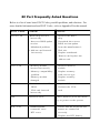
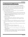
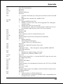
80 Port Frequently Asked Questions
Below is a list of some basic POST Codes, possible problems, and solutions. For
more detailed information about POST Codes, refer to Appendix D in this manual.
P O ST C O D E
P r o bl e m
So l uti o n
FFh o r CFh
1 .B IO S c hip inse rte d
1 . Re inse rt the B IO S
inc o rre c tly
2 . Inc o rre c t BIO S update
ve rsio n
3 . M ainbo ard pro ble m
4 . Add-o n c ard inse rte d
inc o rre c tly.
c hip
2 . D o wnlo ad the c o rre c t
BIO S ve rsio n update
fro m the m anufac ture r's
We b site .
3 . Re plac e m ainbo ard
4 . Re m o ve and re plac e the
add-o n c ard
C1 h - C5 h
1 . M e m o ry m o dule
1 . Re inse rt m e m o ry
inse rte d inc o rre c tly
2 . M e m o ry c o m patibility
m o dule
2 . Re plac e m e m o ry
pro ble m
2Dh
with c o rre c t type
3 . M e m o ry m o dule
dam age d
3 . Re plac e m e m o ry
m o dule
1 . Erro r o c c ure d in VG A
1 . Re plac e VG A c ard
BIO S
2 . VG A c ard inse rte d
2 . Re inse rt the VG A
c ard
inc o rre c tly
26h
O ve rc lo c k e rro r
Cle ar CM O S o r pre ss the inse rt
ke y to po we r o n the syste m
07h - 12h
1 . Initial
Init keKeyboard
ybo ard
c o ntro lle r e rro r
1 . Ensure that the ke ybo ard and
2 . RTC e rro r
c o rre c tly.
2 . Re plac e the RTC batte ry.
m o use are c o nne c te d
Table of Contents
Page
Section 1
Introduction
Package Contents ...................................................... 1-1
Intel Pentium 4 Processors......................................... 1-2
Chipset Components .................................................. 1-2
Accelerated Graphics Port ......................................... 1-3
Ultra ATA66/100 ........................................................ 1-3
Hardware Monitoring ................................................. 1-3
LAN (Optional) .......................................................... 1-3
Serial ATA .................................................................. 1-4
IEEE 1394 (Optional) .................................................. 1-4
Mainboard Form-Factor ............................................. 1-5
I/O Shield Connector .................................................. 1-6
Power-On/Off (Remote) .............................................. 1-6
System Block Diagram ............................................... 1-7
Section 2
Features
Mainboard Features ................................................... 2-1
Section 3
Installation
Mainboard Layout ..................................................... 3-2
Easy Installation Procedure
CPU Installation ......................................................... 3-3
Jumper Settings .......................................................... 3-5
System Memory Configuration .................................. 3-6
Expansion slots .......................................................... 3-9
Device Connectors..................................................... 3-11
External Modem Ring-in Power ON and
Keyboard Power ON Function (KBPO) ..................... 3-18
STR (Suspend To RAM) Function .......................... 3-19
Supports AGP Card 3.3V Protection .......................... 3-20
Section 4
Award BIOS Setup
Main Menu ................................................................ 4-1
Standard CMOS Setup ............................................... 4-2
Advanced BIOS Features .......................................... 4-3
Advanced Chipset Features ...................................... 4-7
Integrated Peripherals ................................................ 4-9
Power Management Setup ......................................... 4-17
PNP/PCI Configuration Setup .................................... 4-22
PC Health Status ........................................................ 4-24
Power BIOS Features ................................................. 4-26
Defaults Menu ........................................................... 4-30
Supervisor/User Password Setting ............................ 4-31
Exit Selecting .............................................................. 4-32
Section 5
Driver Installation
Easy Driver Installation .............................................. 5-1
C-Media Audio Configuration Brief Guide ................ 5-2
Appendix
Appendix A
Update Your System BIOS ......................................... A-1
Appendix B
EEPROM BOIS Remover ............................................ B-1
Appendix C
GHOST 7 Quick Users Guide (Optional) ................... C-1
Appendix D
POST Codes .............................................................. D-1
Page Left Blank
Introduction
Section 1
INTRODUCTION
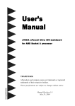
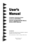
Package Contents
Contents
Deluxe Pack Items
A. Mainboard
I. IEEE 1394 two port cable
B. Users manual
Other Optional Items
C. Floppy drive cable
J. USB2.0 port cable
D. HDD drive cable or round cable
K. S/PDIF Module
E. CD and diskette (drivers and
If you need the other optional item,
please contact dealer for assistance.
utilities)
F. Game port cable
G. I/O Shield
H. S-ATA data and power cable
USERS
MANUAL
B
C
or
E
D
A
F
H
G
I
J
K
Page 1-1
Introduction
Intel® Pentium® 4 processors
The Intel Pentium 4 processor, Intel's most advanced, most powerful processor for
desktop PCs and entry-level workstations, is based on Intel NetBurstTM
microarchitecture. The Pentium 4 processor is designed to deliver performance
across applications and usages where end-users can truly appreciate and experience
the performance. These applications include Internet audio and streaming video,
image processing, video content creation, speech, 3D, CAD, games, multimedia, and
multi-tasking user environments. The Pentium 4 processor delivers this world-class
performance for consumer enthusiasts and business professional desktop PC users
as well as for entry-level workstation users.
Intel adds support for Hyper-Threading Technology to the Pentium 4 processor
family. HT Technology allows a single, physical Pentium 4 processor to function as
two logical processor for next generation multi threaded application.
For more information about all the new features the Pentium 4 delivers check out
the Intel website at http://www.intel.com
Chipset Components
This board is designed with Intel® 865PE (Springdale-PE) chipset. The Intel® 865PE
chipset consists of the Memory Controller Hub (MCH), the I/O Controller Hub
(ICH5/R).
! Memory Controller Hub (MCH)
The MCH provides the interconnect between the AGP, DDR SDRAM and the
system logic. It integrates:
- Supports for single processor with a data transfer rate of 400/533/800MHz.
- Supports dual channel of 266/333/400 DDR SDRAM up to 4GB.
- 8X/4X 1.5V AGP interface (Only support 1.5V on AGP interface).
- Downstream hub link for access to the ICH5/R.
! I/O Controller Hub (ICH5/R)
The I/O controller Hub provides the I/O subsystem with access to the rest of the
system. Additionally, it integrates many I/O functions:
Page 1-2
Introduction
- Upstream hub link for access to the MCH
- 2-Channel Ultra ATA/100 Bus Master IDE controller
- USB controller
- I/O APIC
- SMBus controller
- LPC / Flash BIOS interface
- PCI 2.3 interface
- Integrated System Management Controller
Accelerated Graphics Port (AGP)
The board provides the AGP 3.0 interface. The AGP interface can support external
AGP slot with AGP 8X/4X and Fast Write Transactions. The AGP Interface Specification revision 3.0 enhances the functionality of the original AGP Interface Specification by allowing 8X data transfers (8 data samples per clock) and 1.5 volt (Power
supply) operation. Supports Maximum AGP interface bandwidth 2.1GB/s. (1.5 volt
AGP Card supports only).
Ultra ATA/66/100
The ICH5/R provides an Ultra ATA/66/100 Bus Master IDE controller. This controller
supports Ultra ATA/66/100 protocols which are ideal for supporting demanding
applications such as real-time video, multimedia, and a high performance operating
system. A new IDE cable is required for Ultra ATA/66/100. This cable is an 80-pin
conductor cable, which is backwards compatible with ATA/33 connectors.
Hardware Monitoring
Hardware monitoring enables you to monitor various aspects of the system operation
and status. The features include CPU temperature, voltage and fan speed in RPMs.
LAN (Optional)
The motherboard mounts the LAN chipset. It allows the mainboard to connect to a
local area network by means of a network hub.
Page 1-3
Introduction
Serial ATA
The evolutionary serial ATA interface replaces the standard parallel ATA physical
storage interface. The serial ATA specification provides scalability and allows
future enhancements to the computing platform. Serial technology overcomes
performance limits of parallel interface architecture, meeting the escalating need for
faster data throughput in servers and storage devices.
Serial ATA is backward compatible with current software and runs on existing
architecture without modification. The serial ATA interface cable requires lower
voltages and uses smaller cable connectors, providing ease of installation. You can
easily upgrade storage devices that are compatible with the serial ATA interface
specification.
Serial ATA is completely software compatible with parallel ATA, requiring no
modification to your operating system.
IEEE1394 (Optional)
IEEE 1394 is a high-speed serial bus developed by Apple that allows users to
connect up to 63 devices to the serial bus on a PC. IEEE is sometimes called the
IEEE 1394 standard, the i.Link connector, FireWire, and the High Performance Serial
Bus (HPSB).
IEEE 1394 provides transfer rates up to 400Mbits/sec. IEEE 1394 provides enhanced
PC connectivity for consumer electronics audio/video (A/V) appliances, storage
peripherals, portable devices such as digital cameras, and inter-PC communications.
IEEE 1394 supports hot swapping, multiple speeds on the same bus, and isochronous data transfer providing much needed bandwidth for multimedia operations.
Page 1-4
Introduction
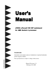
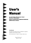
Mainboard Form-Factor
The board is designed with ATX form factor - the latest industry standard of
chassis. The ATX form factor is essentially a Baby-AT baseboard rotated 90
degrees within the chassis enclosure and a new mounting configuration for the
power supply. With these changes the processor is relocated away from the
expansion slots, allowing them all to hold full length add-in cards. ATX defines a
double height aperture to the rear of the chassis which can be used to host a
wide range of onboard I/O. Only the size and position of this aperture is defined,
allowing PC manufacturers to add new I/O features (e.g.; TV input, TV output,
joystick, modem, LAN, audio, etc.) to systems. This will help systems integrators
differentiate their products in the marketplace, and better meet your needs.
By integrating more I/O down onto the board and better positioning the hard
drive and floppy connectors material cost of cables and add-in cards is
reduced.
By reducing the number of cables and components in the system, manufacturing time and inventory holding costs are reduced and reliability will
increase.
By using an optimized power supply, it's possible to reduce cooling costs
and lower acoustical noise. An ATX power supply, which has a sidemounted fan, allows direct cooling of the processor and add-in cards making
a secondary fan or active heatsink unnecessary in most system applications.
Expandable I/O
AT X
Power
Supply
PCI slots
AGP slot
Single chassis
fan for system
ATX 12V power
connector
CPU
ATX power connector
Floppy/IDE
connectors
3 1/2-inch
Bay
5 1/4-inch
Bay
Figure 2: Summary of ATX chassis features
Page 1-5
Introduction
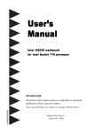
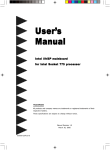
I/O Shield Connector
The board is equipped with an I/O back panel (Figure 3). Ensure that your computer
case has the appropriate I/O cutout.
RJ-45 LAN
(Optional)
Parallel Port
PS/2
Mouse
PS/2
Keyboard
Line-in/Rear out (Blue)
Line-out/Front out (Green)
Mic-in/Center&Subwoofer (Pink)
COM1
USB2.0 USB2.0
ports
ports
Figure 3: I/O ports
Power-On/Off (Remote)
The board has 20-pin ATX and 4-pin ATX12V connectors for power supplies
(Figure 4). For power supplies that support the Remote On/Off feature, this should
be connected to the mainboard front panel PW_ON connector for the computer
power On/Off button.
The board has been designed with Soft Off" function. You can turn off the system
two ways: pressing the front panel power On/Off button, using the "Soft Off"
function (incorporated in the mainboards onboard circuit controller) that can be
controlled by an operating system such as Windows®XP/ME/2000/98/95.
Note: For maintaining the DDR SDRAM power during STR (ACPI S3) function, it is
strongly recommend to use power supplies that have a +5VSB current of (>=)
2A. Please check the 5VSBs specification that has been printed on the power
supplys outer case.
Note: The board requires a minimum of 250 Watt power supply to operate. Your
system configuration (amount of memory, add-in cards, peripherals, etc.) may
exceed the minimum power requirement but to ensure that adequate power is
provided, use a 300 Watt (or greater) power supply.
12V 4-pin
20-pin
PW-ON
Case (chassis) Power ON/OFF button (PW-ON)
Figure 4: Simple ATX power ON/OFF controller
Page 1-6
POWER SUPPLY
Introduction
System Block Diagram
Figure 5: System Block Diagram
Page 1-7
Introduction
Page Left Blank
Page 1-8
.A=JKHAI
Section 2
FEATURES
Mainboard Features
Processor
®
®
! Socket 478 Intel Pentium 4 processor.
Supports Northwood, Prescott or later CPU only, does not support
Willamette CPU.
! Supports System Bus and Memory Configurations:
FSB400 / DDR266 (PC2100)
FSB533 / DDR266/333 (PC2100/PC2700)
FSB800 / DDR333 (PC2700)
FSB800 / DDR400 (PC3200)
* When configured to FSB800/DDR333, adaptive synchronization aligns to the
closest FSB to memory clock ratio, setting memory channel to 320MHz.
! Supports Hyper-Threading Technology
Enabling the functionality of Hyper-Threading Technology for your
computer system requires ALL of the following platform Components:
"CPU:
"Chipset:
"BIOS:
"OS:
®
®
An Intel Pentium 4 Processor with HT Technology.
®
An Intel Chipset that supports HT Technology.
A BIOS that supports HT Technology and has it enabled.
An operating system that supports HT Technology.
Chipset
! Intel 865PE Chipset (865PE + ICH5R or ICH5)
Main Memory
! Four 184-pin DDR DIMM sockets for PC2100/2700/3200 (DDR266/333/400)
DIMMs
! Supports 128-bit dual channel memory architecture
! Supports up to 4GB memory size
Page 2-1
.A=JKHAI
BIOS
! Flash EEPROM with Award BIOS
- ACPI v2.0 compliant
- S3 (Suspend to DRAM) sleep-state support
- SMBIOS (System Management BIOS) v2.2 compliant
- Supports Power failure recovery
- Capable to waked the computer up from specific states by LAN, Power
switch, PME#, RTC alarm, USB, PS2 K/B, PS2 Mouse, Modem Ring-in
COM#1
Onboard PCI Devices
! 1394 -->
Integrate 1394 controller with Agere FW323 for 3 ports solution
(Optional) - IEEE-1394a compliant with up to 400Mbps bandwidth
! S-ATA --> Up to four Serial ATA devices ( 2 for optional by Silicom Image
SIL3112A)
- Suppoers Serial ATA devices with up to 1.5Gbps bandwidth
! LAN -->
Integrate 10/100Mps Fast Ethernet controller with Broadcom
(Optional) BCM4401 LAN Chipset
Integrate 1Gbps Fast Ethernet controller with Broadcom
BCM5705/5788 LAN Chipset (for high-level model only)
! IDE -->
2 IDE Port with PIO/Ultra DMA-33/66/100 up to 4 devices
2 Extra IDE Port by HPT372 with Ultra DMA-133 & IDE RAID
up to 4 devices (Optional)
Legacy IO Controller
! Winbond W83627HF LPC IO controller with floppy, printer, game, serial
and CIR/SIR interface
Audio
! Six channel audio with analog and digital output using CMI9739A AC97
CODEC
- AC97 v2.2 compliant
Page 2-2
.A=JKHAI
- In 2-CH mode, supports Line-In (Blue), Line-Out (Green) and Mic-In
(Pink) at rear panel
- In 6-CH mode, supports Rear speaker out (Blue), Front speaker out
(Green) and Center&Subwoofer speaker out (Pink) at rear panel
- Supports CD-In, Aux-In and S/PDIF-In/out interface
- Supports Line-out and Mic-In for front panel
Peripheral Interfaces
! PS/2 keyboard and mouse ports (at rear panel)
! One Parallel (printer) port (at rear panel)
! Two Serial ports (1 at rear panel)
! Eight USB2.0 ports (4 at rear panel)
! One RJ45 LAN connector (at rear panel)(Optional)
! One game port
! One floppy drive interface
! Two IDE interfaces
! Two IDE&RAID interfaces (Optional)
! Three 1394 interface (Optional)
! Four Serial ATA interface (2 for Optional)
! Three Fan connectors
Front Panel Controller
! Supports Reset & Soft-Off switches
! Supports HDD & Power LEDs
! Supports PC speaker
Expansion Slots
! One AGP slots supporting 1.5v 4X/8X AGP card
- AGP v3.0 compliant
! Five PCI bus sockets with Bus Master support
- PCI v2.3 compliant
Page 2-3
.A=JKHAI
Other Features
! Magic Health a H/W monitoring software utility, for voltages, temperatures and fan-speeds sensing
! EZ Boot An easy way let end-user can choose to boot from hard drive,
CD-ROM, floppy,
! Supports exclusive KBPO (Keyboard Power On) function
! Excellent Over clocking capabilities by
- subtle voltage tuning on CPU, Memory, AGP
- subtle frequency tuning on FSB
- Supports complete FSB/Memory and FSB/AGP, PCI Asynchronous
scheme for over-clocking
! Supports AGP card 3.3V Protection
! P80P for system debugging
Form Factor
! 305 x 245 mm ATX size
Page 2-4
Installation
Section 3
INSTALLATION
Page 3-1
Installation
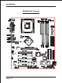
Mainboard Layout
Page 3-2
Installation
Easy Installation Procedure
The following must be completed before powering on your new system:
3-1.
CPU Installation
3-2.
Jumper Settings
3-3.
System Memory Configuration
3-4.
Expansion Slots
3-5.
Device Connectors
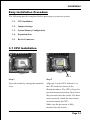
3-1 CPU Installation
Figure 2
Figure 1
Pin 1
Step 1
Step 2
Open the socket by raising the actuation
lever.
Align pin 1 on the CPU with pin 1 on
the CPU socket as shown in the
illustration above. The CPU is keyed to
prevent incorrect insertion. Dont force
the processor into the socket. If it does
not go in easily, check for mis-orientation and reinsert the CPU.
Make sure the processor is fully
inserted into the socket.
Page 3-3
Installation
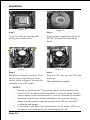
Figure 3
Figure 4
Step 3
Step 4
Close the socket by lowering and
locking the actuation lever.
Apply thermal compound to the top of
the CPU and install the heatsink as
shown.
Figure 5
Figure 6
Step 5
Step 6
Install the cooling fan assembly. Press
the two clips in the direction of the
arrows shown in Figure 5 to secure the
assembly to the CPU socket.
Plug the CPU fan into the CPU fan
connector.
The installation is complete.
NOTES:
Damage to Intel PentiumTM 4 processors might result if installed with
incorrect CPU fan and heatsink assemblies. Use Intels design thermal
solution shown in the illustrations above: an active heatsink; an extruded
aluminum heatsink base; and a fan attached to the top on the fin array.
Apply heatsink thermal compound or paste to the CPU to avoid CPU
overheating and damage.
In accordance with Intel Corp. specifications, do not install a CPU over
50 times to avoid bending the pins and damaging the CPU.
Page 3-4
Installation
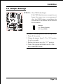
3-2 Jumper Settings
JCMOS: Clear CMOS data Jumper
If the CMOS data becomes corrupted or you
forgot the supervisor or user password,
clear the CMOS data to reconfigure the
system back to the default values stored in
the ROM BIOS.
Settings:
1-2: Normal (Default)
2-3: Clear CMOS
To CMOS Clear data, please follow the steps below.
1. Turn off the system.
2. Change the jumper from 1-2 to 2-3 position
for a few seconds.
3. Replace the jumper on to the 1-2 position.
4. Turn of the system and hold down the <Del>
key to enter BIOS setup.
Page 3-5
Installation
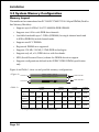
3-3 System Memory Configuration
Memory Layout
The mainboard accommodates four PC2100/PC2700/PC3200 184-pin DIMMs (Dual Inline Memory Modules):
Supports up to 4.0GB of 266/333/400MHz DDR SDRAM.
Supports two 64-bit wide DDR data channels.
Available bandwidth up to 3.2GB/s (DDR400) for single-channel mode and
6.4GB/s (DDR400) in dual-channel mode.
Supports non ECC DIMMs.
Registered DIMMs not supported.
Supports 128-Mb, 256-Mb, 512Mb DDR technologies.
Supports only x8, x16, DDR devices with four banks.
SPD (Serial Presence Detect) scheme for DIMM detection support.
Supports configurations defined in the JEDEC DDR1 DIMM specification
only.
Figure 6 and Table 1 show several possible memory configurations.
<Figure 6>
DDR-A1 DIMM 1 (Black)
Channel A
Dual Channel 2
Channel B
DDR-B2 DIMM 4 (Green)
<Table 1>
1 DIMM
(64- bit)
DIMM#1
(Black)
DIMM#2
(Green)
DIMM#3
(Black)
DMM#4
(Green)
2 DIMM
(128- bit)
SS/DS
SS/DS
SS/DS
SS/DS
SS/DS
SS/DS
SS/DS
* SS: Single-Sided DIMM, DS: Double-Sided DIMM
Page 3-6
Dual Channel 1
DDR-A2 DIMM 2 (Green)
3 DIMM
(64- bit)
SS/DS
SS/DS
SS/DS
SS/DS
SS/DS
SS/DS
SS/DS
SS/DS
4 DIMM
(128- bit)
SS/DS
SS/DS
SS/DS
Installation
NOTES:
When FSB is 400MHz, the mainbaod can support DDR266.
When FSB is 533MHz, the mainbaod can support DDR266/333.
When FSB is 800MHz, the mainbaod can support DDR333/400 (Uses DDR333,
adaptive synchronization aligns to the closest FSB to memory clock ratio, setting
memory channel to 320MHz)
The four DIMM sockets are divided into 2 Channels - Dual Channel 1
(DIMM1 and DIMM3) and Dual Channel 2 (DIMM2 and DIMM4), The same
dual channel has same color as show in Figure 6, Only in keeping those
DIMMs in same type and same size are preferred. We recommend you to use
the same color DIMM sockets to obtain the best memory performance.
- For one DIMM memory configuration, the DIMM can be located on either
of DIMM#1 to DIMM#4 in 64-bit mode.
- For two DIMMs memory configuration, they are prefer to located in same
group so the system can perform 128-bit mode.
- For three DIMMs memory configuration, the DIMMs can be located on all
DIMM sockets in 64-bit mode.
- For four DIMMs memory configuration, the DIMMs can be located on all
DIMM sockets in 128-bit mode.
Using non-compliant memory with higher bus speeds (overclocking) may
severely compromise the integrity of the system.
Page 3-7
Installation
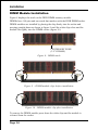
DIMM Module Installation
Figure 8 displays the notch on the DDR DIMM memory module.
DIMMs have 184 pins and one notch that matches with the DDR DIMM socket.
DIMM modules are installed by placing the chip firmly into the socket and
pressing straight down as shown in figure 9 until the white clips close and the
module fits tightly into the DIMM socket (figure 10).
CENTER KEY ZONE
(2.5 V DRAM)
Figure 8 - DIMM notch
Figure 9 - DIMM module clips before installation
Figure 10 - DIMM module clip after installation
To remove the DIMM module press down the white clips and the module is
released from the socket.
Page 3-8
Installation
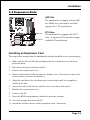
3-4 Expansion Slots
AGP Slot
The mainboard is equipped with an AGP
slot. Make sure you install a card that
supports the 1.5V specification.
AGP Slot
PCI Slots
PCI Slots
The mainboard is equipped with 5 PCI
slots. It supports PCI cards that comply
with the PCI specification.
Installing an Expansion Card
The steps below assume that the mainboard is already installed in the system chassis.
1.
Make sure the PC and all other peripheral devices connected to its has been
powered down.
2.
Disconnect all power cords and cables.
3.
Remove the system unit cover.
4.
Remove the bracket of the slot that you intend to use. (You need to remove the
screw in order to remove the bracket.)
5.
Align the card above the slot then press it down firmly until it is completely
seated in the slot.
6.
Secure the card to the chassis with the screw you removed in step 4.
7.
Replace the system unit cover.
8.
Power on the PC.
9.
Enter the BIOS step program to make the necessary settings.
10. Save the settings and restart the PC.
11. Install the software drivers of the expansion cards, if necessary.
Page 3-9
Installation
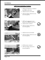
AGP Card Installation Caution
1. AGP card component is blocked
by DIMM socket lock.
2. AGP slot lock is not locked.
3. AGP card edge connector is not
inserted properly.
1. AGP card component is not
blocked by DIMM socket lock.
2. AGP slot lock is locked.
3. AGP card edge connector is
inserted properly.
1. AGP slot lock is not locked.
2. AGP card edge connector is not
inserted properly.
1. AGP slot lock is locked.
2. AGP card edge connector is
inserted properly.
Page 3-10
Installation
3-5 Connectors
Parallel Port
PS/2
Mouse
PS/2
Keyboard
RJ-45 LAN
(Optional)
Line-in/Rear out (Blue)
Line-out/Front out (Green)
Mic-in/Center&Subwoofer (Pink)
COM1
USB2.0 USB2.0
ports
ports
Figure 11 - I/O Ports
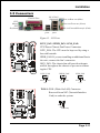
JCPU_FAN JPWR_FAN
JCPU_FAN / JPWR_FAN / JSYS_FAN:
CPU/Power/Chassis Fan Power Connectors
JCPU_FAN: The CPU must be kept cool by using a
fan with heatsink.
JPWR_FAN: If you are installing an additional fan in
the unit, connect the fans connector.
JSYS_FAN: The chassis fan will provide adequate
airflow throughout the chassis to prevent overheating the CPU.
JSYS_FAN
JCPU_FAN
JPWR_FAN
JSYS_FAN
Sence Ground
+12V
NC Ground
+12V
Sence Ground
+12V
WOL1: WOL (Wake On LAN) Connector
Reserved for an NIC (Network Interface
Card) to wake the system.
PME
GND
+5V Standby
Page 3-11
Installation
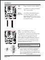
FDD:
Floppy Controller Connector (Black)
IDE1/2:
Ultra DMA-66/100 Primary/Secondary
IDE Connector (Blue)
IDE3/4:
Ultra DMA-66/100 & RAID Primary/
Secondary IDE Connector (Red)
Supported by HPT372 chipset, refer to
HPT372 RAID Controller users manual
for detail information.
IDE2 IDE1
IDE4 IDE3
FDD
34
33
40
(Optional)
39
1
2
FDD
2
1
IDE1/IDE2
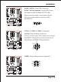
PW1:
PW1
+12V
+5V
5VSB
+12V
Gronud
PW12: 4-pin ATX12V Power Connector
The mainboard is equipped with a standard 20-pin
ATX main power connector and a 4-pin +12V
power connector for connecting an ATX12V
power supply. The plugs of the power cables are
designed to fit in only one orientation. Find the
proper orientation then insert the plugs into the
connectors until they fit in place.
PW12
!
20-pin ATX Power Connector
+5V
+12V
PW-OK
Gronud
+5V
-5V
Gronud
Gronud
Gronud
Gronud
Gronud
+5V
PS-ON
Gronud
3.3V
Gronud
-12V
"
PW12
3.3V
3.3V
PW1
Page 3-12
Caution:
Be sure that the PW1 and PW12 Power Connector must be used
simultaneously or else can not boot-up.
! The board requires a minimum of 250 Watt power
supply to operate. Your system configuration
(amount of memory, add-in cards, peripherals, etc.)
may exceed the minimum power requirement but to
ensure that adequate power is provided, use a 300
Watt (or greater) power supply.
Installation
CFPA: Front Panel Audio Connector
When the jumpers are removed and this
connector is used for front panel audio. The
type of front panel line-out phone jack is
normal close. Without phone plug inserted,
the rear panel audio is enabled. With phone
plug inserted, the rear panel audio is
disabled.
MIC_In
GND
+5V
NC
Front Line-out-R
Rear Line-out-FR
Key
Rear Line-out-FL
Front Line-out-L
'
Settings
Pins (5-6) & (9-10) Short (default): Only the Onboard Rear
Audio Speaker can be used.
Pins (5-6) & (9-10) Open: Only Front Panel Audio Speaker
can be used.
! In 2-Channel audio mode, Mic-In is shared for both front panel and rear panel.
In 6-Channel audio mode, the Mic-In is dedicated for front panel used, and rear
panel Mic-In function will switch to Center and subwoofer support.
CD-IN/AUX-IN: CD Audio_IN Connector
The CD-IN and AUX-IN connectors are used to
receive audio form a CD-ROM drive, TV tuner or
MPEG card.
CD-IN
AUX-IN
CD-IN
AUX-IN
CD_IN_Right
AUX_IN_Right
CD_Reference
1
CD_IN_Left
GND
1
AUX_IN_Left
Page 3-13
Installation
GAME1: Game/MIDI connector
This port works well with any application that is
compatible with the standard PC joystick.
COM2: Serial Port Connector
The serial port can be used with modems, serial
printers, remote display terminals, and other serial
device.
RTS RI
DSR CTS NC
2
10
9
1
DCD TXD Ground
RXD DTR
SPDIF: Sony/Philips Digital InterFace connector
This connector is the digital link between the
mainboard and your audio devices, such as CD
player, sampler or DAT recorder. It allows the
digital transmission of audio data in SPDIF format.
SPDIF_IN VCC
5
1
6
2
NC
GND SPDIF_OUT
Page 3-14
Installation
SATA1 / SATA2: Serial ATA Connectors
SATA3 / SATA4 (Optional): Sserial ATA Connectors support by Silicom Image Sil3112A chip.
SATA2
These connectors enable you to connect Serial
ATA devices that conform to the Serial ATA
specification.
SATA1
SATA4 SATA3
1
GND B+ BA- A+ GND
GND
C1394-1 / C1394-2 / C1394-3: (Optional )
400Mbps 1394a (FireWire) Connectors
C1394-1, C1394-2 and C1394-3 enable you to connect
three IEEE 1394 ports for use with external devices
that conform to the IEEE 1394 specification.
TPB+
+12V (Fused) GND
TPA+
Key
9
1
2
10
C1394-3 C1394-1
C1394-2
GND
TPA+12V (Fused) GND
TPB-
CP80P: 80 port debug connector (Optional )
LED G
Key
LED A
LED F
DGL
1
2
9
10
DGH
LED B
LED C
LED E
LED D
Page 3-15
Installation
LED1: 80 Port Debug LED
Provides two digits LED light to show why system
boots failed for quick and easy optimization.
80 Port Debug 7-segment LED display
(Refer to Appendix E for POST codes)
USB1/USB2/CUSB3/CUSB4: USB 2.0 ports
The mainboard is equipped with eight onboard
USB2.0/1.1 ports (4 at rear panel).
USB1
It is equipped with a 10-pin connector for connecting 4 additional external USB 2.0/1.1 ports. If you
wish to use the additional USB ports, install the
card-edge bracket to the system chassis then insert
the connector that is attached to the USB port
cables to the 10-pin connector.
USB2
USB3
USB4
It will help your device more efficient for the transfer
speed up to 480Mbps.
CAUTION !
Please make sure the USB cable has the
same pin assignment. The different pin
assignment may be caused damage of
system.
If you need the USB cable, please contact
our retailer.
Page 3-16
VCC
VCC
Data0-
Data1-
Data0+
Data1+
GND
GND
Key
NC
'
Installation
CFP: Front Panel Connector
" HD_LED
This will light when the hard drive is being
accessed.
" PWR_LED
This connects to the power button of the
system chassis
CFP / CIR / CSPK
" RST
This switch allows you to reboot without
having to power off the system thus prolonginh
the life of the power supply or system.
" PW_ON
This is connected to the power button on the
case. Using the Soft-Off by Pwr-BTTN feature,
you can choose either Instant Off (turns system
off immediately), or 4 sec delay (push the
button for 4 seconds before the system turns
off). When the system is in 4 sec delay mode,
suspend mode is enabled by pushing the
button momentarily.
CIR: IR connector
Connect your IrDA cable to the IR connector.
1. VCC
4. GND
2. NC
5. IRTX
3. IRRX
CSPK: Speaker
Connect to the systems speaker for beeping
1. VCC
3. GND
2. NC
4. Speaker
Page 3-17
Installation
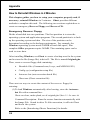
3-6 External Modem Ring-in Power ON and
Keyboard Power ON Functions (KBPO)
Modem-Ring Power ON Function
The I/O chipset provides the two serial ports with the External Modem Ring-in Power
ON function. Once you connect an external modem to COM1 or COM2, the
mainboard enables you to turn on the system through remote and host dial-up
control.
Keyboard Power ON Function
The mainboard features a keyboard power on function that enables you to turn on
the power supply using a keypress. Follow these instructions to enable the Keyboard Power ON function .
Step :
Use the Keyboard Power ON function (KBPO) to turn on the system by using
a key press, password, or hot key combination etc. as set in the BIOS Power
Management Setup menu (refer to the BIOS Power Management Setup for
details). The BIOS default setting is keyboard Hot key (<Ctrl> + <F1>). To power
off the system, use the soft-OFF function under Windows XP/ME/2000/98.
(refer to Windows online help).
NOTES:
Intel ATX version 2.0 specification recommends you use a power supply
that supplies >=2.0 A in 5.0 VSB. However, this mainboard supports a 5.0
VSB standby power supply > = 2A .
We recommend you use the power supply with 2.0 A in 5.0 VSB, which
supports PCI 2.2 specification for remote power-on and wake-up
functions.
Page 3-18
Installation
3-7 STR (Suspend To RAM) Function
This mainboard supports the STR (Suspend To RAM) power management
scheme by maintaining the appropriate power states in the DDR SDRAM
interface signals. The power source to the DDR SDRAM must be kept active
during STR (ACPI S3). Advanced Configuration Power Interface (ACPI)
provides many Energy Saving Features for operating systems that support
Instant ON and QuickStart TM function.
1. Use the STR functionality to save system power, you are recommended to
confirm the following requirements:
a. Install ACPI qualified add-on cards (such as AGP, LAN, and modem cards).
b. In BIOS under Power Management Setup (refer to Section 4), select ACPI
Suspend Type: S3(STR) and USB Port Wake Up Control (if you have a
USB mouse or keyboard device).
c. Install Windows® XP/2000/ME/98SE.
d. Restart the system.
e. Open the Control Panel Power Management application, and click the
Advanced tab. In the Power buttons section, select Stand By from the
drop-down lists.
2. To enable the STR function, click the START button and choose Shut Down. In
the Shut Down Windows dialog box, select the Stand By option to enter STR
mode.
The following lists the differences between STR power saving mode and Green
(or Suspend) mode:
a. STR is the most advanced Power Management mode.
b. STR cuts all the power supplied to peripherals except to memory - max.
power saving.
c. STR saves and keeps all on-screen data including any executed applications
to DDR SDRAM.
d. In STR mode, you must push the power button (connected to the onboard PWOn of CFP pin), click your USB mouse buttons, or press your USB keyboard
keys to wake up your system to the last display.
NOTE: Clicking your PS/2 mouse or pressing a PS/2 keyboard key does not wake the
system from STR mode.
Page 3-19
Installation
3-8 Supports AGP Card 3.3V Protection
The Intel® 865PE chipset supports 1.5 volt AGP graphics cards only. Using a 3.3
volt AGP card in an Intel® 865PE chipset-based board might damage the chipset on
an 865PE-equipped mainboard. However, this mainboard features a protection
function that prevents the system from powering on when a 3.3V AGP card is
inadvertently inserted into the AGP slot.
If this happens, we recommend you to follow these steps:
Step 1:
Remove the 3.3V AGP card from the AGP slot.
Step 2:
Unplug the ATX/ATX12V power cable.
Step 3:
Insert a 1.5V AGP card into the AGP slot.
Step 4:
Wait for 5 ~ 7 seconds and then plug in the ATX/ATX12V power
cord again (or turn on the ATX/ATX12V power switch) to turn on
your system.
Note: There should be an interval of 5 ~ 7 seconds between
unplugging and plugging in the power cord, or turning
the ATX/ATX12V power supply on and off.
Page 3-20
BIOS
Section 4
BIOS SETUP
Main Menu
The ROM BIOS provides a built-in Setup program which allows user to modify the
basic system configuration and hardware parameters. The modified data is stored in
a battery-backed CMOS, so that data will be retained even when the power is turned
off. In general, the information saved in the CMOS RAM will stay unchanged unless
there is a configuration change in the system, such as hard drive replacement or a
device is added.
It is possible for the CMOS battery to fail causing CMOS data loss. If this happens
you will need install a new CMOS battery and reconfigure your BIOS settings.
To enter the Setup Program :
Power on the computer and press the <Del> key during the POST (Power On Self
Test). The BIOS CMOS SETUP UTILITY opens. (Figure 1)
Figure 1: CMOS Setup Utility
Page 4-1
BIOS
The main menu displays all the major selection items. Select the item you need to
reconfigure. The selection is made by moving the cursor (press any direction (arrow
key ) to the item and pressing the Enter key. An on-line help message is displayed
at the bottom of the screen as the cursor is moved to various items which provides a
better understanding of each function. When a selection is made, the menu of the
selected item will appear so that the user can modify associated configuration
parameters.
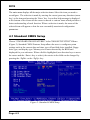
4-1 Standard CMOS Setup
Choose STANDARD CMOS FEATURES in the CMOS SETUP UTILITY Menu
(Figure 2). Standard CMOS Features Setup allows the user to configure system
settings such as the current date and time, type of hard disk drive installed, floppy
drive type, and display type. Memory size is auto-detected by the BIOS and
displayed for your reference. When a field is highlighted (use direction keys to move
the cursor and the <Enter> key to select), the entries in the field can be changed by
pressing the <PgDn> or the <PgUp> key.
Figure 2: Standard CMOS Setup
Page 4-2
BIOS
Notes:
_
If the hard disk Primary Master/Slave and Secondary Master/Slave are
set to Auto, then the hard disk size and model will be auto-detected.
_
The Halt On: field is used to determine when to halt the system by the
BIOS if an error occurs.
_
Floppy 3 Mode support is a mode used to support a special 3.5-inch
drive used in Japan. This is a 3.5-inch disk that stores 1.2 MB. The
default setting for this is disabled.
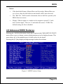
4-2 Advanced BIOS Features
Selecting the ADVANCED BIOS FEATURES option in the CMOS SETUP UTILITY
menu allows users to change system related parameters in the displayed menu. This
menu shows all of the manufacturers default values for the board.
Pressing the [F1] key displays a help message for the selected item.
Figure 3: BIOS Features Setup
Page 4-3
BIOS
Virus Warning
During and after system boot up, any attempt to write to the boot sector or partition
table of the hard disk drive halts the system and an error message appears.
You should then run an anti-virus program to locate the virus. Keep in mind that this
feature protects only the boot sector, not the entire hard drive. The default is
Disabled.
Enabled: Activates automatically when the system boots up causing a warning
message to appear when anything attempts to access the boot sector.
Disabled: No warning message appears when anything attempts to access the boot
sector.
Note: Many disk diagnostic programs that access the boot sector table can
trigger the virus warning message. If you plan to run such a program, we
recommend that you first disable the virus warning.
CPU L1 & L2 Cache
This controls the status of the processors internal Level One and Level Two cache.
The default is Enabled.
Enabled: This activates the processors internal cache thereby increasing
performance.
Disabled: This deactivates the processors internal cache thereby lowering
performance.
Hyper-Threading Technology
Enables the CPU Hyper-Threading Technology.
Options: Enables, Disabled.
Note: Recommends enabling Hyper-Threading Technology on system with
Windows XP and Linux 2.4 and disabling for legacy OS.
Quick Power On Self Test
This category speeds up the Power On Self Test (POST). The default is Enabled.
Enabled: This setting will shorten or skip of the items checked during POST.
Disabled: Normal POST.
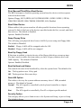
Hard Disk Boot Priority
This item allows you to select the hard disk boot priority.
Page 4-4
BIOS
First /Second/Third/Other Boot Device
The BIOS attempts to load the operating system from the devices in the sequence
selected in these items.
Options: Floppy, LS120, HDD-0, SCSI, CDROM, HDD-1, HDD-2, HDD-3, ZIP100,
USB-FDD, USB-ZIP, USB-CDROM, USB-HDD, LAN, Disabled.
Boot Other Device
When enabled, the system searches all other possible locations for an operating
system if it fails to find one in the devices specified under the first, second, and third
boot devices. The default is Enabled.
Options: Enabled, Disabled.
Swap Floppy Drive
This will swap your physical drive letters A & B if you are using two floppy disks.
The default is Disabled.
Enabled: Floppy A & B will be swapped under the O/S.
Disabled: Floppy A & B will be not swapped.
Boot Up Floppy Seek
If this item is enabled, it checks the size of the floppy disk drives at start-up time.
You dont need to enable this item unless you have a legacy diskette drive with
360K capacity. The default is Disabled.
Options: Enabled, Disabled.
Boot Up NumLock Status
This controls the state of the NumLock key when the system boots. The default is On.
On: The keypad acts as a 10-key pad.
Off: The keypad acts like cursor keys.
Gate A20 Option
This refers to the way the system addresses memory above 1 MB (extended
memory). The default is Normal.
Normal: The A20 signal is controlled by the keyboard controller or chipset
hardware.
Fast:
The A20 signal is controlled by Port 92 or chipset specific method.
Security Option
This category allows you to limit access to the System and Setup, or just to Setup.
The default is Setup.
Page 4-5
BIOS
System:
Setup:
The system will not boot and access to Setup will be denied unless the
correct password is entered at the prompt.
The system will boot, but access to Setup will be denied unless the
correct password is entered at the prompt.
APIC Mode
This item allows you to enable APIC (Advanced Programmable Interrupt Controller)
functionality. APIC is an Intel chip that provides symmetric multiprocessing (SMP)
for its Pentium systems.
Options: Enabled, Disabled.
HDD S.M.A.R.T. Capability
The S.M.A.R.T. (Self-Monitoring, Analysis, and Reporting Technology) system is a
diagnostics technology that monitors and predicts device performance. S.M.A.R.T.
Software resides on both the disk drive and the host computer.
The disk drive software monitors the internal performance of the motors, media, heads,
and electronics of the drive. The host software monitors the overall reliability status of
the drive. If a device failure is predicted, the host software, through the Client WORKS
S.M.A.R.T applet, warns the user of the impending condition and advises appropriate
action to protect the data. The default is Disabled.
Options: Enabled, Disabled.
Full Screen LOGO Show
This item allows you determine Full Screen LOGO display during POST.
Options: Enabled, Disabled.
Page 4-6
BIOS
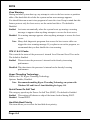
4-3 Advanced Chipset Features
Choose the ADVANCED CHIPSET FEATURES option in the CMOS SETUP
UTILITY menu to display following menu.
Figure 4: Chipset Features Setup
DRAM Timing Selectable
For setting DRAM Timing, By SPD is follow Intel PC DDR SDRAM Serial Presence
Detect Specification.
Options: Manual, By SPD.
CAS Latency Time
Enables you to select the CAS latency time. The value is set at the factory depending
on the DRAM installed. Do not change the values in this field unless you change
specifications of the installed DRAM and DRAM clock from DRAM Timing Selectable.
The default is by DRAM SPD.
Options: 2, 2.5, 3.
Active to Precharge Delay
This item specifies the number of clock cycles needed after a bank active command
before a precharge can occur (sets the minimum RAS pulse width.). The default is by
DRAM SPD.
Options: 5, 6, 7, 8.
Page 4-7
BIOS
DRAM RAS# to CAS# Delay
This item sets the timing parameters for the system memory such as the CAS (Column
Address Strobe) and RAS (Row Address Strobe). The default is by DRAM SPD.
Options: 2, 3, 4.
DRAM RAS# Precharge
This item refers to the number of cycles required to return data to its original
location to close the bank or the number of cycles required to page memory before
the next bank activate command can be issued. The default is by DRAM SPD.
Options: 2, 3, 4.
System BIOS Cacheable
This item allows the system to be cached in memory for faster execution.
Options: Disabled, Enabled.
Video BIOS Cacheable
This item allows the video to be cached in memory for faster execution.
Options: Disabled, Enabled.
Delay Prior to Thermal
Set this item to enable the CPU Thermal function to engage after the specified time.
The default is 16 minutes.
Options: 4, 8, 16, 32 minutes.
AGP Aperture Size (MB)
This item defines the size of the aperture if you use an AGP graphics adapter. It
refers to a section of the PCI memory address range used for graphics memory.
Options: 4, 8, 16, 32, 64, 128, 256 MB.
Init Display First
If two video cards are used (1 AGP and 1 PCI) this specifies which one will be the
primary display adapter.
Options: PCI Slot, Onboard/AGP.
Page 4-8
BIOS
4-4 Integrated Peripherals
Figure 5: Integrated Peripherals
Notes:
If you do not use the Onboard IDE connector, then you will need to set that
Onboard Primary PCI IDE: Disabled and Onboard Secondary PCI IDE: Disabled
The Onboard PCI IDE cable should be equal to or less than 18 inches (45 cm.).
BROADCOM Lan Boot ROM (Optional)
Enables and disables the onboard LAN Boot ROM. The default is Disabled.
Options: Enabled, Disabled.
Page 4-9
BIOS
OnChip IDE Device
Scroll to OnChip IDE Device and press <Enter>. The following screen appears:
[RAID]
IDE HDD Block Mode
IDE Block Mode allows the controller to access blocks of sectors rather than a
single sector at a time. The default is Enabled.
Options: Enabled, Disabled.
On-Chip Primary PCI IDE
The integrated peripheral controller contains an IDE interface with support for two
IDE channels. Select Enabled (default) to activate each channel separately.
Options: Enabled, Disabled.
IDE Primary/Secondary Master/Slave PIO
The four IDE PIO (Programmed Input/Output) fields let you set a PIO mode (0-4)
for each of the four IDE devices that the onboard IDE interface supports. From
Modes 0 to 4 provide successively increased performance. In Auto mode, the
system automatically determines the best mode for each device.
Options: Auto, Mode 0 ~ 4.
IDE Primary/Secondary Master/Slave UDMA
This allows you to select the mode of operation for the IDE drive Ultra DMA-33/
66/100 implementation is possible only if your IDE hard drive supports it and the
operating environment includes a DMA driver. If your hard drive and your system
Page 4-10
BIOS
software both support Ultra DMA-33/66/100, select Auto to enable UDMA mode
by BIOS or you can manually disable it.
Options: Auto, Disabled.
*** On-Chip Serial ATA Setting ***
RAID Function
Enables the RAID function. When RAID is enabled ("Auto" or "Enabled") Serial
ATA ports 0 and 1 will default to "Tertiary" and "Quartenary".
Options: Auto, Enabled, Disabled.
Note: O/S driver for this feature is available only for Windows XP, please check
future updates for other O/S support.
On-Chip Serial ATA
Applicable only when RAID function above is "Disabled". Assigning "Primary"
will make Serial ATA IDE the Primary port and in effect disable the Parallel-ATA
Primary port. Similarly, assigning "Secondary" will disable the Parallel-ATA
Secondary port.
Options: RAID, Disabled, For Primary, For Secondary.
Serial ATA Port 0 /1 Mode
Display Serial ATA Port 0/1 assignment to IDE device.
! The following screen shows RAID function "Auto" or "Enabled".
[RAID]
Display only
<RAID Mode>
Page 4-11
BIOS
! The following screen shows RAID function "Disabled" and on-chip Serial ATA
assigned to "Primary".
Display only
<Compatible Mode>
! The following screen shows RAID function "Disabled" and on-chip Serial ATA
assigned to "Secondary".
Display only
<Compatible Mode>
Page 4-12
BIOS
Onboard PCI Device Setup
Scroll to Onboard PCI Device Setup and press <Enter>. The following screen appears:
USB Controller
Enables the all USB controller.
Options: Disabled, Enabled.
USB 2.0 Controller
Enables the EHCI (USB2.0) controller.
Options: Disabled, Enabled.
USB Keyboard Support
Your system contains a Universal Serial Bus (USB) controller and you have a USB
keyboard. The default is Auto detect.
Options: Auto, Enabled, Disabled.
USB Mouse Support
Your system contains a Universal Serial Bus (USB) controller and you have a USB
Mouse . The default is Disabled.
Options: Enabled, Disabled.
AC97 Audio
This item allows you to decide to auto or disable the chipset family to support
AC97 Audio. The function setting AC97 Audio Codec states. The system default
is Auto.
Options: Auto, Disabled.
Game Port Address
Select an address for the Game port.
Options: 201, 209, Disabled.
Page 4-13
BIOS
Midi Port Address
Select an address for the Midi port.
Options: 290, 300, 330, Disabled.
Midi Port IRQ
Select an interrupt for the Midi port.
Options: 5, 10.
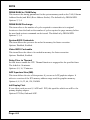
HighPoint Device (Optional)
Enables the onboard HighPoint RAID feature.
Options: Enabled, Disabled, Auto.
Onboard LAN Device (Optional)
Enables the onboard LAN feature.
Options: Enabled, Disabled.
Onboard SIT3112 (Optional)
Enables the onboard Serial ATA feature.
Options: Enabled, Disabled.
Onboard IC-FW323 1394 (Optional)
Enables the onboard IEEE 1394 feature.
Options: Enabled, Disabled.
Page 4-14
BIOS
Onboard I/O Chip Setup
Scroll to Onboard I/O Chip Setup and press <Enter>. The following screen appears:
Onboard FDC Controller
Select Enabled if your system has a floppy disk controller (FDC) installed on the
system board and you wish to use it. If you install add-in FDC or the system has
no floppy drive, select Disabled in this field.
Options: Enabled, Disabled.
Onboard Serial Port 1/2
Select an address and corresponding interrupt for the first and second serial ports.
Options: 3F8/IRQ4, 2E8/IRQ3, 3E8/IRQ4, 2F8/IRQ3, Disabled, Auto.
UART Mode Select
This filed allows the users to configure what IR mode the 2nd serial port should
use. The default is Normal.
Options: Normal, IrDA and ASKIR.
RxD, TxD Active
This field configures the receive and transmit signals generated from the IR port.
The default is Hi Lo (when UART Mode Select is not set to Normal).
Options: Hi Hi, Hi Lo, Lo Hi, and Lo Lo.
IR Transmission delay
This item allows you to enabled/disable IR transmission delay.
Options: Enabled, Disabled.
UR2 Duplex Mode
This item allows you to select IR half/full duplex function.
Options: Half, Full.
Page 4-15
BIOS
Use IR Pins
This item allows you to select IR transmission routes, one is RxD2, TxD2 (COM
Port) and the other is IR-Rx2Tx2.
Options: IR-Rx2Tx2, RxD2, TxD2.
Onboard Parallel Port
This field allows the user to configure the LPT port.
Options: 378/IRQ7, 278/IRQ5, 3BC/IRQ7, Disabled.
Parallel Port Mode
This field allows the user to select the parallel port mode.
Options: SPP, EPP, ECP, ECP+EPP.
EPP Mode Select
This item allows you to determine the IR transfer mode of onboard I/O chip.
Options: EPP1.9, EPP1.7.
ECP Mode USE DMA
This field allows the user to select DMA1 or DMA3 for the ECP mode.
Options: DMA1, DMA3.
Page 4-16
BIOS
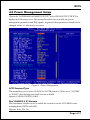
4-5 Power Management Setup
Choose the POWER MANAGEMENT SETUP in the CMOS SETUP UTILITY to
display the following screen. This menu allows the user to modify the power
management parameters and IRQ signals. In general, these parameters should not be
changed unless its absolutely necessary.
Figure 6: Power Management
ACPI Suspend Type
This item allows you to select S1(POS) or S3(STR) function. When set to S3(STR)
or S1&S3 the following two fields become available.
Options: S1(POS), S3(STR), S1&S3.
Run VGABIOS if S3 Resume
This determines whether or not to enable the system to run the VGA BIOS when
resuming from S3(STR) or S1&S3.
Options: Auto, Yes, No.
Page 4-17
BIOS
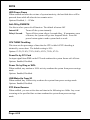
S3 KB Wake-up Function
This determines whether or not to enable keyboard/mouse activity to awaken the
system from S3(STR) or S1&S3.
Options: AnyKey or Mouse, By PowerOn Func., AnyKey, Mouse.
POWER ON Function
Enables computer power on by keyboard, mouse, or hotkey activity. The default is
Hot KEY.
Password:
Requires you to enter a password when using the keyboard
to power on. Set the password in the next field KB Power ON
Password.
HotKEY:
Enables you to use a hot key combination to power on the
computer. Set the hot key combination in the Hot Key Power
ON field.
AnyKEY:
Enables you to set any keyboard activity to power on the
computer.
BUTTON ONLY: Requires you to push the computer power button to power on
the system.
Keyboard 98:
Enables you to set the Windows 98 key to power on the system.
Keyboard Power ON Password
Press Enter to create a password that is required when you use the keyboard to
power on the system. You must set the POWER ON Function to Password to be
prompted for a password at power on.
Hot Key Power ON
Enables you to set a hot key combination to be used for powering on the system.
The default is Ctrl-F1.
Options: Ctrl-F1 ~ Ctrl F12.
PWRON After PWR-Fail
This item enables your computer to automatically restart or return to its last operating status after power returns from a power failure.
Off:
The system stays off after a power failure.
Former-Sts:
The system returns to the state it was in just prior to the power
failure.
Page 4-18
BIOS
Power Management
Use this to select your Power Management selection. The default is User define.
Max. saving: Maximum power savings. Inactivity period is 1 minute in each mode.
Min. saving: Minimum power savings. Inactivity period is 1 hour in each mode.
User define: Allows user to define PM Timers parameters to control power saving
mode.
Video Off Method
This option allows you to select how the video will be disabled by the power
management. The default is V/H Sync + Blank
V/H Sync + Blank: System turns off vertical and horizontal synchronization ports
and writes blanks to the video buffer.
DPMS Support:
Select this option if your monitor supports the Display Power
Management Signaling (DPMS) standard of the Video
Electronics Standards Association (VESA). Use the software
supplied for your video subsystem to select video power
management values.
Blank Screen:
System only writes blanks to the video buffer.
Video Off In Suspend
Lets you enable the video to power off in suspend mode.
No: Video power off not controlled by power management.
Yes: Video powers off after time shown in suspend mode setting.
Suspend Type
Determines CPU status during power saving mode.
Stop Grant:
CPU goes into idle mode during power saving mode.
PwrOn suspend:
CPU and system remain powered on in suspend mode.
MODEM Use IRQ
Name the interrupt request (IRQ) line assigned to the modem (if any) on your
system. Activity of the selected IRQ always awakens the system. Default is IRQ 3.
Options: N/A, 3, 4, 5, 7, 9, 10, 11
Suspend Mode
enabled and after the set time of system inactivity, all devices except the CPU will be
shut off.
Options: Disabled, 1, 2, 4, 8, 12, 20, 30, 40 Min and 1 Hour.
Page 4-19
BIOS
HDD Power Down
When enabled and after the set time of system inactivity, the hard disk drive will be
powered down while all other devices remain active.
Options: Disabled, 1 ~ 15 Min.
Soft-Off by PWRBTN
Use this to select your soft-off function. The default is Instant Off.
Instant Off:
Turns off the system instantly.
Delay 4 Second : Turns off the system after a 4 second delay. If momentary press
of button, the system will go into Suspend Mode. Press the
power button again to make system back to work.
CPU THRM-Throttling
This item sets the percentage of time that the CPU is idled if CPU throttling is
initiated by excess heat. The default setting is 50%.
Options: 12.5%, 25.0%, 37.5%, 50.0%, 62.5%, 75.0%, 87.5%.
PowerOn by PCI Card
An input signal form PME on the PCI card awakens the system from a soft off state.
Options: Enabled, Disabled.
Power On by Ring or WOL
When enabled, any modem or LAN activity awakens the system from power savings
mode.
Options: Enabled, Disabled.
USB Wake-Up From S3
When enabled, any USB activity awakens the system from power savings mode.
Options: Enabled, Disabled.
RTC Alarm Resume
When enabled, you can set the date and time in the following two fields. Any event
occurring at the specified date or time awakens the system from power savings
mode.
Page 4-20
BIOS
** Reload Global Timer Events **
Primary/Secondary IDE 0/1
Any activity occuring on these channels awakens the system from power savings
mode.
FDD, COM, LPT Port
When enabled, any event occurring on these ports awakens the system from power
savings mode.
PCI PIRQ[A-D]#
When enabled, any event occurring on these PCI slots awakens the system from
power savings mode.
Page 4-21
BIOS
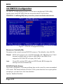
4-6 PNP/PCI Configuration
The PNP/PCI configuration program is for the user to modify the PCI/ISA IRQ
signals when various PCI/ISA cards are inserted in the PCI or ISA slots.
WARNING: Conflicting IRQs may cause the system to not find certain devices.
Figure 7: PNP/PCI Configuration Setup
Resources Controlled By
Determines what controls system PNP/PCI resources. The default is Auto (ESCD).
Manual: PNP Cards resources are controlled manually. The IRQ Resources field
becomes available and you can set which IRQ-X and DMA-X are
assigned to PCI/ISA PNP or Legacy ISA Cards.
Auto:
If your ISA card and PCI cards are all PNP cards, BIOS assigns the
interrupt resource automatically.
PCI/VGA Palette Snoop
This item is designed to overcome problems that can be caused by some nonstandard
VGA cards. This board includes a built-in VGA system that does not require palette
snooping so you must leave this item disabled.
Options: Enabled, Disabled.
Page 4-22
BIOS
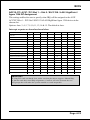
AGP SLOT / AC97 / PCI Slot 1 ~ Slot 5 / SIL3112A / LAN / HighPoint /
Agere 1394 INT Assignment
This setting enables the user to specify what IRQ will be assigned to the AGP/
AC97/PCI Slot 1 ~ PCI Slot 5/SIL3112A/LAN/HighPoint/Agere 1394 devices in the
chosen slot.
Options: Auto, 3, 4, 5, 7,9 ,10, 11, 12, 14 & 15. The default is Auto.
Interrupt requests are shared as shown below:
IN T A
AGP Slot
IN T B
IN T C
IN T D
IN T E
IN T F
IN T G
AC97
V
Slot 1
V
Slot 2
V
Slot 3
V
Slot 4
V
Slot 5
V
O nboard LAN (O ptional)
V
O nboard HighPoint (O ptional)
V
O nboard Serial ATA (O ptional)
V
O nboard IEEE 1394 (O ptional)
O nboard USB1
V
V
O nboard USB2
V
O nboard USB3
O nboard USB4
V
V
USB 2.0
SM BUS
IN T H
V
V
V
IMPORTANT!
If using PCI cards on shared slots, make sure that the drivers support Shared IRQ
or that the cards dont need IRQ assignments. Conflicts will arise between the two
PCI groups that will make the system unstable or cards inoperable.
Page 4-23
BIOS
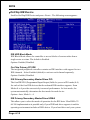
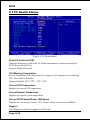
4-7 PC Health Status
33oC/91oF
59oC/138oF
0 RPM
0 RPM
0 RPM
1.50V
1.75V
2.50V
4.97V
12.12V
-12.28V
-5.09V
3.48V
4.89V
Figure 8: PC Health Status
Show PC Health in POST
When this function is enabled the PC Health information is displayed during the
POST (Power On Self Test).
Options: Enabled, Disabled.
CPU Warning Temperature
Sets the temperature at the time which the computer will respond to an overheating
CPU. The default is Disabled.
Options: Disabled, 50OC/122OF ~ 70OC/158OF.
Current CPU Temperature
Displays the current CPU temperature.
Current System Temperature
Displays the current system temperature.
Current CPU/Chassis/Power FAN Speed
Displays the current speed of the CPU, chassis, and power fan speed in RPMs.
Vagp (V)
The voltage level of Power supplied to AGP card.
Page 4-24
BIOS
Vcore (V)
The voltage level of the CPU(Vcore).
Vdimm(V)
The voltage level of the DRAM.
VBAT(V)
The voltage level of the battery.
± 5V, ± 12V, 5VSB(V)
The voltage level of the switching power supply.
ACPI Shutdown Temperature
This is the temperature that the computer will turn off the power to combat the
effects of an overheating system. (requires ACPI to be enabled in Power Management BIOS and ACPI compliant operating system.) The default is Disabled.
Options available are 60oC/140oF to 95oC/203oF in increments of 5oC.
Page 4-25
BIOS
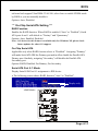
4-8 Power BIOS Features
66
33
1.75V
1.75V
1.50V
1.50V
2.50V
2.50V
Figure 9: Frequency/Voltage Control
Watching-Dog Function
If you select enabled and overclock fail before POST code 26h, the system will reset
automatically by default configuration.
Options: Enabled, Disabled.
CPU FSB/SPEED
Enables you to set the CPU front side bus speed. The default is 100 MHz. Enables
you to adjust CPU clock 1MHz by step. Pressing Enter displays the following
screen:
Key in the DEC (decimalism) number for the CPU FSB/SPEED.
Page 4-26
BIOS
Note: Overclocking failure will cause system No display problem. At this
moment, please press Insert key to back to the initial or default
setting to boot up your system.
Memory Frequency
Enables you to select a ratio of the Double Data Rate Synchronous DRAM to match
the installed DRAM frequency 266/333/400MHz. We recommend that you leave this
item at the default value.
When the FSB is 400MHz the options will display 3:4 =>DDR266.
When the FSB is 533MHz the options will display 1:1 =>DDR266, 4:5 =>DDR333 and
Auto =>DDR333 (by SPD).
When the FSB is 800MHz the options will display 1:1=>DDR400, 5:4=>DDR320 and
Auto=>DDR320 (by SPD).
CPU Clock Ratio
Use this item to select a multiplier for the system front side bus (FSB) frequency.
The value of the multiplier must be set so that:
Multiplier x Front side Bus Frequency = CPU Clock Speed
For example, if you have a processor that is rated to run at 800 MHz and the
system is running a front side bus frequency of 100 MHz, you should select a
multiplier of 8 so that:
8 (Multiplier) x 100 MHz (front side bus) = 800 MHz (CPU clock)
Key in the DEC (decimalism) number for the CPU Clock Ratio.
Page 4-27
BIOS
AGP/PCI Clock
Enables you to set the host clock to work concurrently with the PCI bus or the AGP
bus. The default is AUTO.
AUTO:
The system sets the item automatically.
AGP-FSB*2/3 PCI-FSB/3: The system sets the host clock to work with the PCI
and AGP bus.
By subtle tuning item:
The system sets the host clock according to the
number produced by the subtle tuning item.
AGP/PCI subtle tuning
Enables you to set the AGP/PCI frequency, enables you to subtle tuning AGP clock
1MHz by step. The default is 66 MHz. Pressing Enter displays the following screen:
Key in the DEC (decimalism) number for the AGP/PCI subtle tuning.
In the following items, Default Voltage indicates the original factory value,
and New Voltage indicates the value that you assign.
CPU Vcore Voltage
This item allows you to set the CPU Vcore voltage. The default is -0.075V.
Options: -0.100V to +0.2875V in 0.0125V increments. We recommend that you leave
this at the default value.
AGP Voltage
This item allows you to set the AGP slot voltage. The default is +0.00V.
Options: +0.00V to +0.70V in 0.10V increments. We recommend that you leave this at
the default value.
Page 4-28
BIOS
DIMM Voltage
This item allows you to set the DIMM slot voltage. The default is +0.00V.
Options: +0.00V to +0.70V in 0.10V increments. We recommend that you leave this at
the default value.
Clock Generation for EMI
Scroll to Clock Generation for EMI and press <Enter>. The following screen
appears:
Auto Detect PCI Clk
When enabled the mainboard automatically disables the clock source for a PCI
slot which does not have a module in it, reducing EMI (ElectroMagnetic
Interference). The default is Enabled.
Spread Spectrum Modulated
If you enable spread spectrum, it can significantly reduce the EMI
(ElectroMagnetic Interference) generated by the system.
Page 4-29
BIOS
4-9 Defaults Menu
Selecting Defaults from the main menu shows you two options which are described below
Load Fail-Safe Defaults
When you press <Enter> on this item you get a confirmation dialog box:
Load Fail-Safe Defaults (Y/N) ? N
Pressing Y loads the BIOS default values for the most stable, minimal-performance
system operations.
Load Optimized Defaults
When you press <Enter> on this item you get a confirmation dialog box:
Load Optimized Defaults (Y/N) ? N
Pressing Y loads the default values that are factory settings for optimal performance system operations.
Page 4-30
BIOS
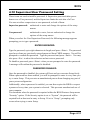
4-10 Supervisor/User Password Setting
These items are used to install a password. A Supervisor password takes precedence over a User password, and the Supervisor limits the activities of a User.
You can set either a supervisor or user password, or both of them:
Supervisor password:
authorized to enter and change the options of the setup
menus.
User password:
authorized to enter, but not authorized to change the
options of the setup menus.
When you select Set User/Supervisor Password, the following message appears
prompting you to type a password:
ENTER PASSWORD:
Type the password, up to eight characters in length, and press <Enter>. The password
typed now clears any previously entered password from CMOS memory. You will be
prompted to confirm the password. Type the password and press <Enter>. You may
also press <Esc> to abort the selection and not enter a password.
To disable a password, press <Enter> when you are prompted to enter the password.
A message will confirm the password is disabled:
PASSWORD DISABLED.
Once the password is disabled, the system will boot and you can enter Setup freely.
When a password has been enabled, you will be prompted to enter it every time you
try to enter Setup. This prevents an unauthorized person from changing any part of
your system configuration.
Additionally, when a password is enabled, you can also require the BIOS to request
a password every time your system is rebooted. This prevents unauthorized use of
your computer.
You determine when the password is required within the BIOS Features Setup menu
Security option. If the Security option is set to System, the password will be
required both at boot and at entry to Setup. If set to Setup, prompting only
occurs when trying to enter Setup.
Page 4-31
BIOS
4-11 Exiting BIOS
Save & Exit Setup
Pressing <Enter> on this item asks for confirmation:
Save to CMOS and EXIT (Y/N)? Y
Pressing Y stores the selections made in the menus in CMOS a special section
of memory that stays on after you turn your system off. The next time you boot
your computer, the BIOS configures your system according to the Setup selections
stored in CMOS. After saving the values the system is restarted again.
Exit Without Saving
Pressing <Enter> on this item asks for confirmation:
Quit without saving (Y/N)? Y
This allows you to exit Setup without storing in CMOS any change. The previous
selections remain in effect. This exits the Setup utility and restarts your computer.
Page 4-32
Drivers Installation
Section 5
Driver Installation
Easy Driver Installation
INTEL SPRINGDALE SERIES (865) CHIPSET DRIVER
INTEL CHIPSET INF FILES
C-MEDIA AUDIO DRIVER
(Optional)
BROADCOM LAN DRIVER (EXPLORER FOLDER)
BROADCOM LAN DRIVER (README.HTM)
USB V2.0 (README.HTM)
HPT370(A)/372/372N DRIVER (Please install the driver from 3.5 floppy)
(Optional)
HPT370(A)/372/372N RAID ADMINISTRATOR
SILICON IMAGE DRIVER
ICH5R RAID DRIVER
DRIVER MANUAL
CD EXPLORER EXIT
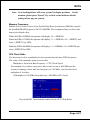
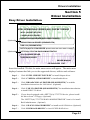
Insert the bundled CD-disk, the main menu screen will appear. The main menu
displays buttons that link you to the supported drivers, utilities and software.
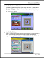
Step 1 :
Click INTEL CHIPSET INF FILES to install chipset driver.
Step 2 :
Click C-MEDIA AUDIO DRIVER to install audio driver.
Step 3 :
Click BROADCOM LAN DRIVER (README.HTM) to read the
installation instructions for LAN driver. (Optional)
Step 4 :
Click USB V2.0 DRIVER (README.HTM) for installation introduction
to install USB V2.0 driver.
Step 5 :
If your board equipped with a HPT370(A)/372/372N device, please install
the driver from 3.5 floppy. (Optional)
The HPT370(A)/372/372N RAID ADMINISTRATOR item is for install
Raid Administrator. (Optional)
Step 6 :
Click SILICON IMAGE DRIVER to install serial ATA driver. (Optional)
Step 7 :
Click ICH5R RAID DRIVER to install ICH5R RAID driver.
Page 5-1
Drivers Installation
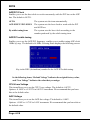
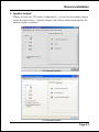
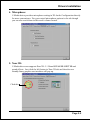
C-Media Audio Configuation Brief Guide
Below is list brief guide of C-Media Audio Configuration. For more detailed
information, please refer to users manual in the attached CD.
You are able to access the control panel from two places:
a) The system tray in the right-bottom of your screen. You can click right button
of the mouse on it to get an audio-related pop-up menu as follows
b) In the Control Panel (Start=>Setting=>Control Panel), double-click CMI
Audio Config to open it.
Page 5-2
Drivers Installation
1. Speaker output:
When you open the 3D Audio Configuration, you will see the default Output
tab as the figure below. Speaker Output tab collects main setting/options for
analog output to speakers.
<2 channel mode>
<6 channel mode>
Page 5-3
Drivers Installation
2. S/PDIF:
C-Media driver supports digital S/PDIF output (Sony/Philips Digital InterFace,
developed by SONY/PHILIPS to provide a low-distortion digital data transfer
between audio devices). There may be an optical or coaxial connector for S/PDIF
on your system. When you select S/PDIF tab, you will see the setting page as the
figure below.
3. Volume Control:
C-Media driver provides the digital volume control for all 6 channels in 3D
Audio Configuration. You can regulate each volume to the speaker for current
playing digital sound sources. Its not effective for analog input sources.
Page 5-4
Drivers Installation
4. Microphone:
C-Media driver provides microphone setting in 3D Audio Configuration directly
for more convenience. You can control microphone options in the tab though
you can also reach them in Microsoft volume control.
5. Xear 3D:
C-Media driver now supports Xear 3D- 5.1 Virtual SPEAKER SHIFTER and
sound effects. Just click the left button in Xear 3D tab and then the new
friendly/fancy graphic user interface will pop up.
Click this
Page 5-5
Drivers Installation
!"Xear 3D - 5.1 Virtual SPEAKER SFIFTER:
The SPEAKER SHIFTER block provides an advanced, amazing and considerate
feature- dynamically adjustable multi-channel sound system no matter what
listening appliance you use and what application you are running. You do NOT
have to endure unbalanced speaker placement due to spatial limitation. You can
enjoy multi-channel surround sound with even an earphone or usual 2 speakers.
!"
!"Xear 3D - Sound Effect:
Xear 3D Advanced Program provides another functional block- Sound Effect.
You can create a different feeling for your music including 27 Environment
Effects, Environment Size & 10-Band Equalizer with 12 pre-set models.
Page 5-6
Drivers Installation
!"
!"Xear 3D - Multi-channel Music Demo:
This demo program provides each speaker testing and three 5.1-channel music.
You can get feeling about 5.1-channel surround music and use it to test
SPEAKER SHIFTER, too. All demo music/sound here will repeat playing if you
dont press Stop button.
!"
!"Xear 3D - Play3D Demo:
Xear 3D Advanced Program also provides interesting Play3D demo programs as
below. After installing the program with setup program, you will find the
program from the path: Start->Programs->C-Media 3D Audio->Play3D Demo.
Page 5-7
Drivers Installation
6. Information :
There is a C-Media audio-related Information tab in 3D Audio Configuration.
You can get a whole picture about the audio chip, driver version, 3D Audio
Engine, Microsoft DirectX Version, and Configuration Version itself.
Page 5-8
Appendix
Appendix A
A-1 Update Your System BIOS
Download the xxxxx.EXE file corresponding to your model form the our website to
an empty directory on your hard disk or floppy. Run the downloaded xxxxx.EXE
file and it will self extract. Copy these extracted files to a bootable DOS floppy
disk.
Note: The DOS floppy disk should contain NO device drivers or other programs.
1. Type A:\AWDFLASH and press <Enter> Key.
2. You will see the following setup on screen.
3. Please key in the xxxxx.bin BIOS file name.
XXXX
4. If you want to save the previous BIOS data to the diskette, please key in [Y],
otherwise please key in [N].
XXXX
XXXXX
xxxxx.bin
A-1
Appendix
5. Key in File Name to save previous BIOS to file.
XXXX
XXXXX
xxxxx.bin
xxxxx.bin
6. Are you sure to program (y/n), please key in [Y] to start the programming.
XXXX
XXXXX
xxxxx.bin
xxxxx.bin
7. The programming is finished.
XXXX
XXXXX
xxxxx.bin
F1 : Reset
A-2
F10 : Exit
Appendix
Appendix B
B-1 EEPROM BIOS Remover
Do not remove the BIOS chip, unless instructed by a technician and only with a
PLCC IC extractor tool.
The BIOS socket may be damaged if using an improper method to
replace the BIOS chip.
B-1
Appendix
Page Left Blank
B-2
Appendix
Appendix C
C-1 GHOST 7 Quick User’s Guide (Optional)
Installation is very easy. You only need to copy the Ghost7 folder or Ghost.exe to
your hard disk.
Main Menu
Description of Menu
Ghost clones and backs up Disk and Partition.
In which Disk indicates hard disk options
Partition indicates partition options
Check indicates check options
Disk
C-1
Appendix
There are 3 hard disk functions:
1. Disk To Disk (disk cloning)
2. Disk To Image (disk backup)
3. Disk From Image (restore backup)
Important!
1. To use this function, the system must have at least 2 disks. Press the Tab key to
move the cursor.
2. When restoring to a destination disk, all data in that disk will be completely
destroyed.
Disk To Disk (Disk Cloning)
1. Select the location of the Source drive.
2. Select the location of the Destination drive.
3. When cloning a disk or restoring the backup, set the required partition size as
shown in the following figure.
4. Click OK to display the following confirmation screen. Select Yes to start.
C-2
Appendix
Disk To Image (Disk Backup)
1. Select the location of the Source drive.
2. Select the location for storing the backup file.
3. Click OK to display the following confirmation screen. Select Yes to start.
Disk From Image(Restore Backup)
1. Select the Restoring file.
C-3
Appendix
2. Select the Destination drive of the disk to be restored.
3. When restoring disk backup, set the required partition size as shown in the
following figure.
4. Click OK to display the following confirmation screen. Select Yes to start.
Partition
C-4
Appendix
There are 3 partition functions:
1. Partition To Partition (partition cloning)
2. Partition To Image (partition backup)
3. Partition From Image (restore partition)
Partition To Partition (Partition Cloning)
The basic unit for partition cloning is a partition. Refer to disk cloning for the
operating method.
Partition To Image (Partition Backup)
1. Select the disk to be backed up.
2. Select the first partition to be backed up. This is usually where the operating
system and programs are stored.
3. Select the path and file name to store the backup file.
C-5
Appendix
4. Is the file compressed? There are 3 options:
(1) No: do not compress data during backup
(2) Fast: Small volume compression
(3) High: high ratio compression. File can be compressed to its minimum, but
requiring longer execution time.
5. Select Yes to start performing backup.
Partition From Image (Restore Partition)
1.
Select the backup file to be restored.
2. Select the source partition.
C-6
Appendix
3. Select the disk to be restored.
4. Select the partition to be restored.
5. Select Yes to start restoring.
Check
This function is to check possible error caused by defective FAT or
track during backup or restoring.
C-7
Appendix
How to Reinstall Windows in 2 Minutes
This chapter guides you how to setup your computer properly and, if
necessary, reinstall Windows in 2 minutes. Ghost provides different
methods to complete this task. The following two sections explain how to
create an emergency Recover Floppy and Recover CD:
Emergency Recover Floppy
Divide a hard disk into two partitions. The first partition is to store the
operating system and application programs. The second partition is to back
up the operating system and data. The size of the partition can be
determined according to the backup requirements. For example, the
Windows operating system needs 200MB of hard disk space, Plus
complete Office programs require 360MB. The remaining space can be
used to store data.
After installing Windows, use Ghost to create a backup area for the system
and to store the file (Image file) in drive D. The file is named Original.gho.
Then, create a recover floppy disk containing:
!" Bootable files (Command.com, Io.sys, and MSDOS.SYS )
!"Config.sys (configuration setup file)
!"Autoexec.bat (auto-execution batch file)
!"Ghost.exe (Ghost execution file)
There are two ways to create the content of the recover floppy for
restoring:
(1) To load Windows automatically after booting, store the Autoexec.
bat file with a command line:
Ghost.exe clone, mode=pload, src=d:\original.gho:2,dst=1:1 -fx -sure -rb
Command Description: Runs the restore function automatically with
the Image File. Stored in drive D. After execution, it will exit Ghost
and boots the system.
Refer to the [Introducing Ghosts Functions] for details.
C-8
Appendix
(2) After booting, the screen displays the Menu. Select Backup or Restore:
Since the user may install other applications in the future, he/she may
alter Autoexec.bat file to back up or restore the user-defined Image
file as follows:
#
Backup
Back up Windows and application programs as a file (Recent.
gho). Command is:
Ghost clone,mode=pdump,src=1:1,dst=d:\Recent.gho -fx sure -rb
#
Restore
Restore types include [General Windows] and [Windows and
Application Programs]. If you select [General Windows],
the system is restored to the general Windows operation
condition. The command is:
Ghost.exe -clone,mode=pload,src=d:\Original.gho,dst=1:1 -fx
-sure -rb
If you select [Windows and Application Programs], the latest
backup file (Recent.gho) is restored, skipping the installation
and setup of application programs.
For description of related parameters, refer to [Introducing Ghosts
Functions].
For more information about menu design, refer to Config.sys and
Autoexec.bat under /Menu in the CD. You can also create a backup CD
containing Ghost.exe and these two files.
C-9
Appendix
Recover CD
The following is a simple guide to create a recover CD:
1. First, create a recover floppy disk contains the following with any
copy program such as Easy CD Create (Note 2) :
Bootable files (Command.com and Io.sys and MSDOS.SYS)
Config.sys (Configuration setup file)
Autoexec.bat (Auto-execution batch file)
Mscdex.exe (CD-Rom execution file)
Ghost.exe (Ghost execution file)
Oakcdrom.sys (ATAPI CD-ROM compatible driver)
The content of Config.sys is:
DEVICE=Oakcdrom.sys /d:idecd001
The content of Autoexec.bat includes:
MSCDEX.EXE /D:IDECD001 /L:Z
Ghost.exe clone,mode=load,src=z:\original.gho,dst=1 -sure -rb
2. Write the backup image file (original.gho) of the entire hard disk or
partition into the recover CD. Use the Recover CD to boot up the
system and restore the backup files automatically.
For description of related parameters, refer to [Introducing Ghosts
Functions].
Note: For more details about copy the creation program and method to create a
recover CD, please refer to the releated software and its associated
operating manual.
Note: Ghost may be executed in interactive or in batch mode. Most of the Ghost
switches are used to assist in batch mode operation. To list switches, type
ghost.exe -h.
C-10
Appendix
Appendix D
D-1 POST CODES
POST (hex)
DESCRIPTION
CFh
C0h
Test CMOS R/W functionality.
Early chipset initialization:
- Disable shadow RAM
- Disable L2 cache (socket 7 or below)
- Program basic chipset registers
Detect memory
- Auto-detection of DRAM size, type and ECC.
- Auto-detection of L2 cache (socket 7 or below)
Expand compressed BIOS code to DRAM
Call chipset hook to copy BIOS back to E000 & F000 shadow RAM.
Expand the Xgroup codes locating in physical address 1000:0
Reserved
Initial Superio_Early_Init switch.
Reserved
1. Blank out screen
2. Clear CMOS error flag
Reserved
1. Clear 8042 interface
2. Initialize 8042 self-test
1. Test special keyboard controller for Winbond 977 series Super I/O
chips.
2. Enable keyboard interface.
Reserved
1. Disable PS/2 mouse interface (optional).
2. Auto detect ports for keyboard & mouse followed by a port &
interface swap (optional).
3. Reset keyboard for Winbond 977 series Super I/O chips.
Reserved
Test F000h segment shadow to see whether it is R/W-able or not. If test
fails, keep beeping the speaker.
Reserved
Auto detect flash type to load appropriate flash R/W codes into the run
time area in F000 for ESCD & DMI support.
Reserved
Use walking 1s algorithm to check out interface in CMOS circuitry.
Also set real-time clock power status, and then check for override.
Reserved
Program chipset default values into chipset. Chipset default values are
MODBINable by OEM customers.
Reserved
Initial Early_Init_Onboard_Generator switch.
Reserved
C1h
C3h
C5h
01h
02h
03h
04h
05h
06h
07h
08h
09h
0Ah
0B-0Dh
0Eh
0Fh
10h
11h
12h
13h
14h
15h
16h
17h
D-1
Appendix
18h
19-1Ah
1Bh
1Ch
1Dh
1Eh
1Fh
20h
21h
22h
23h
24-26h
27h
28h
29h
2A-2Ch
2Dh
2E-32h
33h
34-3Bh
3Ch
3Dh
3Eh
3Fh
40h
41h
42h
D-2
Detect CPU information including brand, SMI type (Cyrix or Intel) and
CPU level (586 or 686).
Reserved
Initial interrupts vector table. If no special specified, all H/W
interrupts are directed to SPURIOUS_INT_HDLR & S/W
interrupts to SPURIOUS_soft_HDLR.
Reserved
Initial EARLY_PM_INIT switch.
Reserved
Load keyboard matrix (notebook platform)
Reserved
HPM initialization (notebook platform)
Reserved
1. Check validity of RTC value:
e.g. a value of 5Ah is an invalid value for RTC minute.
2. Load CMOS settings into BIOS stack. If CMOS checksum fails, use
default value instead.
3. Prepare BIOS resource map for PCI & PnP use. If ESCD is valid,
take into consideration of the ESCDs legacy information.
4. Onboard clock generator initialization. Disable respective clock
resource to empty PCI & DIMM slots.
5. Early PCI initialization:
-Enumerate PCI bus number
-Assign memory & I/O resource
-Search for a valid VGA device & VGA BIOS, and put it into C000:0.
Reserved
Initialize INT 09 buffer
Reserved
1. Program CPU internal MTRR (P6 & PII) for 0-640K memory
address.
2. Initialize the APIC for Pentium class CPU.
3. Program early chipset according to CMOS setup.
Example: onboard IDE controller.
4. Measure CPU speed.
5. Invoke video BIOS.
Reserved
1. Initialize multi-language
2. Put information on screen display, including Award title, CPU type,
CPU speed .
Reserved
Reset keyboard except Winbond 977 series Super I/O chips.
Reserved
Test 8254
Reserved
Test 8259 interrupt mask bits for channel 1.
Reserved
Test 8259 interrupt mask bits for channel 2.
Reserved
Reserved
Appendix
43h
44h
45-46h
47h
48h
49h
4A-4Dh
4Eh
4Fh
50h
51h
52h
53-54h
55h
56h
57h
58h
59h
5Ah
5Bh
5Ch
5Dh
5E-5Fh
60h
61-64h
65h
66h
67h
68h
69h
6Ah
6Bh
6Ch
6Dh
Test 8259 functionality.
Reserved
Reserved
Initialize EISA slot
Reserved
1. Calculate total memory by testing the last double word of each 64K
page.
2. Program writes allocation for AMD K5 CPU.
Reserved
1. Program MTRR of M1 CPU
2. Initialize L2 cache for P6 class CPU & program CPU with proper
cacheable range.
3. Initialize the APIC for P6 class CPU.
4. On MP platform, adjust the cacheable range to smaller one in case
the cacheable ranges between each CPU are not identical.
Reserved
Initialize USB
Reserved
Test all memory (clear all extended memory to 0)
Reserved
Display number of processors (multi-processor platform)
Reserved
1. Display PnP logo
2. Early ISA PnP initialization
-Assign CSN to every ISA PnP device.
Reserved
Initialize the combined Trend Anti-Virus code.
Reserved
(Optional Feature) Show message for entering AWDFLASH.EXE
from FDD (optional)
Reserved
1. Initialize Init_Onboard_Super_IO switch.
2. Initialize Init_Onbaord_AUDIO switch.
Reserved
Okay to enter Setup utility; i.e. not until this POST stage can users enter
the CMOS setup utility.
Reserved
Initialize PS/2 Mouse
Reserved
Prepare memory size information for function call: INT 15h ax=E820h
Reserved
Turn on L2 cache
Reserved
Program chipset registers according to items described in Setup & Autoconfiguration table.
Reserved
1. Assign resources to all ISA PnP devices.
2. Auto assign ports to onboard COM ports if the corresponding item
in Setup is set to AUTO.
D-3
Appendix
6Eh
6Fh
70-72h
73h
74h
75h
76h
77h
78h-79h
7Ah
7B-7Eh
7Fh
80h-81h
82h
83h
84h
85h
86-92h
93h
94h
95h
96h
FFh
D-4
Reserved
1. Initialize floppy controller
2. Set up floppy related fields in 40:hardware.
Reserved
(Optional Feature) Enter AWDFLASH.EXE if :
-AWDFLASH is found in floppy drive.
-ALT+F2 is pressed
Reserved
Detect & install all IDE devices: HDD, LS120, ZIP, CDROM ..
Reserved
Detect serial ports & parallel ports.
Reserved
Detect & install co-processor
Reserved
1. Switch back to text mode if full screen logo is supported.
-If errors occur, report errors & wait for keys
-If no errors occur or F1 key is pressed to continue:
!"Clear EPA or customization logo.
Reserved
1. Call chipset power management hook.
2. Recover the text fond used by EPA logo (not for full screen logo)
3. If password is set, ask for password.
Save all data in stack back to CMOS
Initialize ISA PnP boot devices
1. USB final Initialization
2. NET PC: Build SYSID structure
3. Switch screen back to text mode
4. Set up ACPI table at top of memory.
5. Invoke ISA adapter ROMs
6. Assign IRQs to PCI devices
7. Initialize APM
8. Clear noise of IRQs.
Reserved
Read HDD boot sector information for Trend Anti-Virus code
1. Enable L2 cache
2. Program boot up speed
3. Chipset final initialization.
4. Power management final initialization
5. Clear screen & display summary table
6. Program K6 write allocation
7. Program P6 class write combining
1. Program daylight saving
2. Update keyboard LED & typematic rate
1. Build MP table
2. Build & update ESCD
3. Set CMOS century to 20h or 19h
4. Load CMOS time into DOS timer tick
5. Build MSIRQ routing table.
Boot attempt (INT 19h)