1
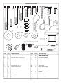
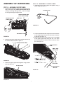
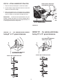
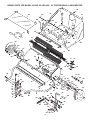
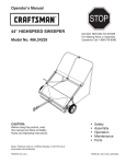
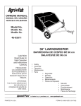
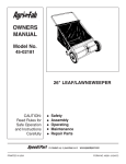
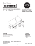
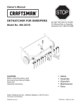
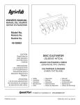
Operators
Manual
2007-08
O0707001
42 Inch
Lawn Sweeper
(45-0352)
Operator's Manual
SAFETY RULES
Any power equipment can cause injury if operated improperly or if the user does not understand how to operate the equipment.
Exercise caution at all times, when using power equipment.
1. Read the vehicle and sweeper owners manuals and
know how to operate your vehicle and sweeper before
using this sweeper attachment. Always instruct other
users before they operate the sweeper.
2. Do not permit children to operate sweeper.
3. Do not permit anyone to ride on sweeper.
4. Never attach the hopper rope to any part of your body
or clothing! Never hold onto the rope while towing the
sweeper! Attach the rope to the towing vehicle to keep
it away from wheels and rotating parts.
5. Operate the sweeper at reduced speed on rough terrain,
near ditches and on hillsides to prevent loss of control.
6. Vehicle braking and stability may be affected with
the attachment of this sweeper. Do not fill sweeper to
maximum capacity without checking the capability of the
towing vehicle to safely pull and stop with the sweeper
attached. Stay off of steep slopes.
7. Stop and inspect vehicle and sweeper for damage after
striking an object. Repair any damage before continuing
operation.
8. Keep sweeper away from fire. Excessive heat can damage
the brushes and hopper bag and could cause the bag
and its contents to burn.
9. Before storing the sweeper, always empty the hopper
bag to avoid spontaneous combustion.
10. Follow maintenance and lubrication instructions as
outlined in the maintenance section of this manual.
Look for this symbol to point out important safety precautions. It means--Attention!!
Become alert!! Your safety is involved.
CARTON CONTENTS
11. Rope
12. Hopper Bag
13. Wind Screen
14. Upper Hopper Tube, L.H.
15. Upper Hopper Tube, R.H.
16. Lower Hopper Tube, L.H.
17. Lower Hopper Tube, R.H.
18. Hopper Bag Pivot Rod
19. Hopper Support Rod (2)
20. Bag Retainer Strap
21. Bag Frame Strap
1. Sweeper Housing Assembly
2. Bag Arm Tube (2)
3. Hitch Tube, R.H. (Right Hand)
4. Hitch Bracket, Bent
5. Hitch Bracket, Straight
6. Hitch Pin Bracket
7. Height Adjustment Strap
8. Lower Height Adjust Handle
9. Upper Height Adjust Handle
10. Hitch Tube, L.H. (Left Hand)
15
17
21
2
14
18
16
20
19
1
13
3
12
7
8
9
2
4
5
11
10
6
2
SHOWN FULL SIZE
A
B
C
E
D
F
G
H
I
J
K
W
V
L
T
O
U
X
M
N
P
Y
Q
S
R
AA
Z
NOT SHOWN FULL SIZE
BB
CC
DD
EE
FF
HH
REF.
QTY.
A
B
C
D
E
F
G
H
I
J
K
L
M
N
O
P
Q
R
2
1
1
4
1
4
6
2
1
6
1
21
2
6
2
1
4
2
DESCRIPTION
REF.
QTY.
Hex Bolt, 5/16-18 x 3" Lg.
Hex Bolt, 5/16-18 x 2-1/2" Lg.
Hex Bolt, 5/16-18 x 2-1/4" Lg.
Hex Bolt, 5/16-18 x 1-3/4" Lg.
Hex Bolt, 5/16" x 1-1/4"
Hex Bolt, 5/16" x 1"
Hex Bolt, 5/16" x 3/4"
Curved Head Bolt, 5/16" x 1-5/8"
Carriage Bolt, 3/8" x 1"
Screw, #10-32 x 5/8"
Nylock Nut, 3/8"
Nylock Nut, 5/16"
Hex Nut, 5/16"
Nylock Nut, #10-32
Palnut
Washer, 7/16"
Washer, 5/16"
Lock Washer, 5/16"
S
T
U
V
W
X
Y
Z
AA
BB
CC
DD
EE
FF
GG
HH
II
2
1
6
1
2
2
2
1
2
4
1
1
2
1
1
2
1
3
DESCRIPTION
Bowed Washer, 5/16"
Hair Cotter Pin, Large
Hair Cotter Pin, Small
Cotter Pin, 1/8" x 3/4"
Clevis Pin, 3/8" x 1/2"
Clevis Pin, 1/4" x 1-1/8"
Clevis Pin, 1/4" x 1-3/4"
Spacer, Small
Spacer, Hitch
Hopper Mount Clamp
Angle Bracket
Grip
Vinyl Cap
Hitch Pin
Spring, Hitch Pin
Plastic Plug
Extension Spring
GG
II
ASSEMBLY OF SWEEPER
STEP 4 - CONNECT HITCH TUBES
6. Fasten the hitch tubes together using two 5/16" x 3" hex
bolts and 5/16" nylock nuts. Do not tighten yet. See
figure 2.
TOOLS REQUIRED FOR ASSEMBLY
(1)
(1)
(1)
(1)
(2)
(1)
Knife or Scissors
Screwdriver
Hammer
3/8" Open End or Box End Wrench
1/2" Open End or Box End Wrench
3/8" Open End or Box End Wrench
5/16" x 3"
HEX BOLT
STEP 1 - REMOVE PARTS FROM CARTON
1. To protect painted parts, lay them on cardboard or a
mat.
2. Remove the sweeper housing, the loose parts and the
hardware package from the carton. Lay out the parts
and hardware as shown on pages 3 and 4.
5/16" NYLOCK NUT
STEP 2 - INSTALL HITCH TUBES
FIGURE 2
3. The hitch tubes are stamped with a "77L" for the left tube
and a "76R" for the right tube. The sweeper housing is
marked with an "L" on the left side and an "R" on the
right side. See figure 1.
4. Hold the left hitch tube against the left side of the sweeper
so that the "77L" on the tube faces away from the sweeper.
Attach the hitch tube using two 5/16" x 1-3/4" hex bolts
and 5/16" nylock nuts. Repeat for the right hitch tube,
but with the "76R" facing in toward the right side of the
sweeper. Do not tighten yet. See figure 1.
STEP 5 - ASSEMBLE HITCH PIN
7. Assemble the hitch pin bracket , the hitch spring and then
the 7/16" flat washer onto the hitch pin. Secure them to
the hitch pin with a 1/8" x 3/4" cotter pin placed into the
middle hole in the hitch pin. Spread ends of cotter pin
around hitch pin. See figure 3.
8. Assemble the hitch pin bracket to the straight hitch
bracket using a 3/8" x 1" carriage bolt and a 3/8" nylock
nut. Align the brackets and tighten. See figure 3.
STEP 3 - REMOVE PLASTIC TIE
5. Remove the plastic tie that fastens the height adjustment
tube to the front of the sweeper housing. See figure 1.
3/8" x 1" CARRIAGE BOLT
5/16" NYLOCK NUT
1/8" x 3/4" COTTER PIN
5/16" x 1-3/4"
HEX BOLT
HOUSING
MARKED "L"
7/16" FLAT WASHER
HITCH SPRING
HITCH BRACKET
(STRAIGHT)
HITCH PIN
BRACKET
3/8" NYLOCK NUT
MIDDLE HOLE
HITCH PIN
PLASTIC TIE
TUBE
MARKED
"77L"
FIGURE 3
HITCH TUBE (L.H.)
FIGURE 1
STEP 6 - MEASURE TRACTOR HITCH
9. If your tractor hitch measures 10" or more above the
ground go to STEP 7a. If your tractor hitch measures
less than 10" above the ground go to STEP 7b.
4
STEP 8 - TIGHTEN BOLTS
STEP 7a - ASSEMBLE HITCH BRACKETS
14. At this time tighten the four bolts in figure 1 that fasten
the hitch tubes to the sweeper housing. Next, tighten
the two bolts in figure 2 that fasten the ends of the hitch
tubes together. Finally, tighten the two bolts in figure 4
or 5 that fasten the hitch brackets to the hitch tubes.
(For tractor hitches 10" or more above the ground.)
10. Place the bent hitch bracket on top of the hitch tubes and
place the straight hitch bracket with hitch pin underneath
the hitch tubes. Fasten together using a 5/16" x 2-1/2"
hex bolt (front), a 5/16" x 2-1/4" hex bolt (rear) and two
5/16" nylock nuts as shown in figure 4. The bolts should
straddle the front hitch tube bolt. Do not tighten yet.
STEP 9 - ASSEMBLE THE ANGLE BRACKET
15. Assemble the angle bracket to the sweeper housing
using two 5/16" x 3/4" hex bolts and 5/16" nylock nuts.
The upright portion of the angle bracket should face
toward the left side of the sweeper. See figure 6.
11. Assemble the two hitch spacers onto the hitch pin and
secure the pin with the large hairpin cotter. See figure 4.
LARGE
HAIRPIN
COTTER
5/16" x 2-1/2"
HEX BOLT
HITCH
BRACKET
(BENT)
HITCH
SPACERS
HITCH PIN
BRACKET
5/16" NYLOCK NUT
5/16" x 2-1/4"
HEX BOLT
ANGLE
BRACKET
5/16" x 3/4"
HEX BOLT
HITCH BRACKET
(STRAIGHT)
5/16" NYLOCK NUTS
FIGURE 4
FIGURE 6
STEP 7b - ASSEMBLE HITCH BRACKETS
(For tractor hitches less than 10" above the ground.)
12. Place the bent hitch bracket underneath the hitch tubes
and place the straight hitch bracket with hitch pin on
top of the hitch tubes. Fasten together using a 5/16" x
2-1/2" hex bolt (front), a 5/16" x 2-1/4" hex bolt (rear)
and two 5/16" hex lock nuts as shown in figure 5. The
bolts should straddle the front hitch tube bolt. Do not
tighten yet.
STEP 10 - ASSEMBLE HEIGHT ADJUST
HANDLE
16. Assemble the plastic grip onto the upper height adjust
handle. See figure 7.
17. Fasten the upper and lower height adjust handles together
as shown in figure 7. Use one 5/16" x 1" hex bolt, one
5/16" x 1-1/4" hex bolt, two 5/16" washers and two 5/16"
nylock nuts. Place the washers against the slots in the
upper handle. Tighten the nuts and then loosen 1/2 turn
so that the handles slide easily. See figure 7.
13. Assemble the two hitch spacers onto the hitch pin and
secure the pin with the large hairpin cotter. See figure 5.
5/16" x 2-1/2"
HEX BOLT
5/16" x 2-1/4"
HEX BOLT
5/16" x 1-1/4" HEX BOLT
PLASTIC GRIP
HITCH PIN
BRACKET
HITCH
BRACKET
(STRAIGHT)
HITCH
SPACERS
HITCH
BRACKET
5/16" WASHER
5/16" x 1" HEX BOLT
5/16" NYLOCK NUTS
5/16" NYLOCK NUT
5/16" WASHER
LARGE HAIRPIN COTTER
FIGURE 7
FIGURE 5
5
STEP 11 - ASSEMBLE EXTENSION SPRING
STEP 13 - ATTACH HEIGHT ADJUST STRAP
TO ANGLE BRACKET
18. Assemble a 5/16" x 1" hex bolt and a 5/16" nylock nut
into the top hole in the height adjustment handles. See
figure 8.
21. Place the height adjust strap between the angle bracket
and the height adjustment handle. Attach the height adjust
strap to the angle bracket using a 5/16" x 1" hex bolt,
the small spacer, a 5/16" washer and a 5/16" nylock nut.
Tighten. See figure 10.
19. Assemble the extension spring onto the end of the upper
bolt and the middle bolt in the height adjust handles.
Assemble a 5/16" nylock nut onto each bolt so that one
thread of the bolt extends through the nut. See figure 8.
5/16" x 1" HEX BOLT
5/16" x 1" HEX BOLT
HEIGHT ADJUST
STRAP
5/16" NYLOCK NUT
SPACER (SMALL)
5/16" WASHER
5/16" NYLOCK NUT
EXTENSION SPRING
5/16" NYLOCK NUT
FIGURE 8
FIGURE 10
STEP 12 - ATTACH HEIGHT ADJUST HANDLE
STEP 14 - ATTACH HEIGHT ADJUST STRAP
TO HEIGHT ADJUST HANDLE
20. Assemble the height adjust handles to the height
adjustment tube on the front of the sweeper housing.
Use two curved head bolts, bowed washers, 5/16" lock
washers and 5/16" hex nuts. Do not tighten yet. See
figure 9.
22. Attach the height adjust strap to the height adjust handle
using a 5/16" x 1" hex bolt, 5/16" washer and 5/16" nylock
nut. Place the washer against the slot in the height adjust
strap. Tighten the nut and then loosen 1/2 turn so that the
strap can slide freely. See figure 11.
23. Slide the height adjust handle so that it aligns with the
height adjust strap and the angle bracket. Tighten the
height adjustment handle in place. See figure 11.
5/16" HEX NUT
5/16" LOCK
WASHER
5/16" WASHER
BOWED
WASHER
5/16" x 1"
HEX BOLT
CURVED
HEAD BOLT
HEIGHT
ADJUSTMENT
TUBE
FIGURE 9
FIGURE 11
6
5/16" NYLOCK NUT
ASSEMBLY OF HOPPER BAG
STEP 16 - ASSEMBLE LOWER TUBES
4. Assemble the two lower hopper tube together using a
plastic plug. See figure 15.
STEP 15 - ASSEMBLE UPPER TUBES
1. Insert the left hand upper hopper tube through the stitched
flaps of the hopper bag, starting at the center cut out
in the top of the bag. See figures 12, 13 and 14. Repeat
for the right hand upper hopper tube.
PLASTIC PLUG
UPPER HOPPER TUBE
(LEFT HAND SHOWN)
CENTER CUT OUT
(START HERE)
LOWER
HOPPER
TUBE
BAG FLAP
FIGURE 15
Right
Left
END HERE
5. Place the assembled lower hopper tubes into the bottom
of the hopper bag and then slide the tubes to the back
of the bag. See figure 16.
6. Attach the ends of the lower hopper tubes to the inside
of the upper hopper tubes using two 3/8" x 1/2" clevis
pins inserted from the inside, and two small hair cotter
pins. See figure 16.
FIGURE 12
2. Slide the two upper hopper tubes together and line up
the center holes as shown in figure 13.
UPPER HOPPER TUBES
UPPER HOPPER
TUBE
SMALL HAIR
COTTER PIN
LOWER HOPPER TUBE
FIGURE 13
3/8" x 1/2"
CLEVIS PIN
3. Fasten the upper hopper tubes together using a plastic
plug. See figure 14.
PLASTIC PLUG
HOPPER BAG
BOTTOM
FIGURE 16
FIGURE 14
7
STEP 18 - ATTACH BAG SIDES
STEP 17 - ATTACH BAG BOTTOM
9. Fold the bag flaps around the lower hopper tubes and
attach to the bag bottom using the snaps. See figure
19.
7. Assemble the bag retainer and the bag frame strap to the
front edge of the bag bottom. Place the bag retainer on
top and the bag frame strap underneath the bag bottom.
Fasten together using six #10 x 5/8" screws and #10-32
nylock nuts. See figure 17.
FRONT EDGE OF BAG BOTTOM
FRAME STRAP
FLAP
SNAP
#10-32 x 5/8" SCREW
BAG RETAINER
#10-32
NYLOCK NUT
FIGURE 17
FIGURE 19
STEP 19 - ASSEMBLE SUPPORT RODS
IMPORTANT: Do not over bend the support rods during
the following step. Over bending will decrease the supporting
tension of the rods.
8. Assemble the bag frame strap to the holes in the lower
hopper tubes using two 1/4" x 1-1/8" clevis pins and
small hair cotter pins. See figure 18.
10. Assemble the two hopper support rods as shown in
figure 20. Place the ends of the rods into the holes in
the upper and lower hopper tubes, flexing the rod just
enough to fit into the holes in the tubes.
BAG FRAME STRAP
SMALL HAIR
COTTER PIN
CLEVIS PIN (N)
SUPPORT
RODS
FIGURE 18
FIGURE 20
8
STEP 20 - ASSEMBLE HOPPER ROD, TUBES
AND CLAMPS
VINYL CAP
5/16" NYLOCK NUT
5/16" x 3/4"
HEX BOLT
11. If the hole in the side of the upper hopper tubes is
covered over by the bag, locate the hole by touch. It is
approximately midway along the side of the bag. Pierce
holes through the stitched bag flaps where the holes in
both hopper tubes are located. See figure 21.
UPPER HOPPER TUBE
PALNUT
MOUNTING CLAMP
FIGURE 23
STEP 21 - ATTACH ROPE
16. Secure the rope to the center of the upper rear hopper
tube as shown in figure 24.
FIGURE 21
12. Slide the hopper bag pivot rod through the hole in an
upper hopper tube. Assemble a mounting clamp, two
bag arm tubes and another mounting clamp onto the
rod as shown in figure 22. Push the rod on through the
upper hopper tube on the opposite side of the bag.
PIVOT ROD
FIGURE 24
STEP 22 - ATTACH HOPPER BAG
17. To attach the hopper bag to the sweeper, slide the ends
of the bag arm tubes into the ends of the hitch tubes
and secure with two 1/4" x 1-3/4" clevis pins and small
hairpin cotters. See figure 25.
MOUNTING CLAMP
FIGURE 22
BAG ARM TUBE
BAG ARM TUBE
13. Assemble the two remaining hopper mount clamps onto
the pivot rod on the outside of the bag. Fasten them to
the inside clamps using four 5/16" x 3/4" hex bolts and
5/16" nylock nuts. Tighten securely. See figure 23.
14. Assemble two palnuts onto the ends of the pivot rod by
lightly tapping them with a hammer. See figure 23.
15. Place a vinyl cap onto each bag arm tube. See figure 23.
1/4" X 1-3/4"
CLEVIS PIN
SMALL
HAIRPIN
COTTER
HINT: To ease assembly of the palnuts, place the bag on
its side on a hard surface. With the bottom end of the
pivot rod against the surface, tap a palnut onto the top
end of the rod. Repeat for other end of rod.
FIGURE 25
9
HITCH
TUBE
HITCH
TUBE
STEP 22 - ATTACH SWEEPER TO TRACTOR
BRUSH HEIGHT ADJUSTED
APPROXIMATELY MID-WAY
1. Place the tractor and sweeper on a flat level surface.
2. Set the sweeper height adjustment handle to about the
middle of its adjustment range.
3. Attach the sweeper hitch to the tractor hitch, arranging
the hitch spacers in one of six possible combinations as
shown in GROUP A and GROUP B diagrams below.
IMPORTANT: To obtain the best performance from your
sweeper, arrange the spacers so that the sweeper bag is
approximately level with the ground and approximately 5" to
7" off the ground as shown in figure 26.
APPROXIMATELY LEVEL
(5" to 7" FROM SURFACE)
FIGURE 26
GROUP "B" - For vehicles with hitches
having 10" to 13" ground clearance.
GROUP "A" - For vehicles with hitches
having 8" to 10" ground clearance.
HITCH BRACKET MOUNTED
ABOVE HITCH TUBES
HITCH BRACKET MOUNTED
BELOW HITCH TUBES
BLACK LINE IS TRACTOR HITCH
BLACK LINE IS TRACTOR HITCH
10
OPERATION
KNOW YOUR SWEEPER
WINDSCREEN
PIVOT ROD
BAG ARM
TUBE
HOPPER
ROPE
HEIGHT
ADJUSTMENT
HANDLE
HEIGHT
ADJUSTMENT
STRAP
HITCH
BRACKETS
HOPPER BAG
Hopper Bag
Collects grass clippings, leaves and debris.
Hopper Rope
Permits dumping of hopper bag from driver's seat.
Windscreen
Helps prevent collected material from being blown out of hopper bag.
Bag Arm Tubes
Connects the hopper bag to the sweeper housing.
Pivot Rod
Allows hopper bag to tilt forward to dump material.
Height Adjustment Handle
Adjusts the operating height of the sweeper.
Height Adjustment Strap
Holds the height adjustment handle in position when locked.
Hitch Bracket
Connects the sweeper to the towing vehicle. Adjusts for various height tractor hitches.
HOW TO USE YOUR SWEEPER
DUMPING OF SWEEPER
3. Your sweeper can be dumped easily without getting off
of the tractor. Pull the rope forward to dump the hopper.
Always empty hopper after each use.
BRUSH HEIGHT ADJUSTMENT
1. To adjust your sweeper brushes to the best operating
height, lift up on the height adjustment handle to
disengage it from the height adjustment strap. Move the
handle forward or backward to raise or lower the brush.
See figure 26. Best adjustment is when the brush setting
is 1/2" down into the grass. Always mow the grass to an
even height before sweeping.
CAUTION: Never attach the hopper rope to any
part of your body or clothing! Never hold onto the
rope while towing the sweeper! Attach the rope
to the towing vehicle to keep it away from wheels
and rotating parts.
SWEEPING SPEED
2. Try a starting speed of approximately 3 m.p.h. (third gear
on most tractors). Depending on the conditions, it may
be necessary to adjust the sweeping speed in order to
achieve best results.
CAUTION: Keep sweeper away from fire.
Excessive heat can damage the brushes and
hopper bag and could cause the bag and its
contents to burn.
11
MAINTENANCE
CLEANING
SCHEDULED MAINTENANCE
6. Clean sweeper housing with a soft brush or cloth.
7. Clean debris from hopper bag with a brush or broom.
8. Remove any material which has wrapped around
brushes or ends of brush shaft.
1. Clean the sweeper after each use.
2. Inspect for worn or damaged parts, such as brushes
and wheels.
3. Lubricate the brush shaft bearing twice a year with a
few drops of light weight oil. See figure 27.
HEIGHT ADJUSTMENT SLOT
OIL BEARINGS HERE
STORAGE
FLAT WASHER
CAUTION: Before storing the sweeper,
always empty the hopper bag to avoid
spontaneous combustion.
HEX BOLT
FIGURE 27
1. Clean the sweeper and hopper bag thoroughly to help
prevent rust and mildew.
2. To collapse the hopper bag for storage, remove the two
hopper support rods from the rear of the hopper.
3. Store in a dry area.
4. Lubricate the wheel bearings each season. Remove the
hub cap and apply a few drops of light weight oil.
5. Every two years, remove the wheels and clean the gears
found inside the wheel housing. After cleaning, lubricate
the gears with an even coat of light grease. To remove
the wheel, pop off the hub cap and remove the lock nut,
flat washer and hub cap washer. See figure 28.
HEX BOLT
FLAT WASHER
FLAT WASHER
HUB CAP
SPACER
HUB CAP
WASHER
NYLOCK NUT
FIGURE 28
12
SERVICE AND ADJUSTMENTS
WHEEL GEAR AND PAWL SERVICE
BRUSH REPLACEMENT
IMPORTANT: Do not remove both wheels at the same
time to avoid mixing of parts. (The R.H. and L.H. ratchet
gears are not interchangeable.) Make notes on the position
of washers and snap rings during disassembly.
NOTE: Brush replacement should be done one brush at
a time.
1. Remove only one wheel from the sweeper.
2. Remove the retaining rings and washers which hold the
ratchet gear onto the brush shaft.
3. Remove the gear by sliding it off the brush shaft. (Look
for the drive pin, which may fall out of the brush shaft
when the ratchet gear is removed.) See figure 30.
4. To reassemble, insert the drive pin through the hole near
the end of the brush shaft. Make sure the pin slides back
and forth easily in the shaft. See figure 30.
5. Lightly grease the shaft and fill the ratchet gear with
grease. Assemble the ratchet gear back onto the shaft.
See figure 30.
6. Lightly grease the axle and the gear teeth on the wheel,
and then reassemble the wheel. The brushes should
rotate only during forward rotation of the wheel. If the
brushes are driven (rotated) by both forward and reverse
rotation of the wheel, the drive pin is jamming in the
ratchet gear. Disassemble to clean and lubricate the
drive pin and the ratchet gear. See figure 30.
7. Remove the second wheel and repeat the procedure.
1. Remove the hopper bag from the sweeper.
2. Loosen only the two hex bolts and lock nuts which clamp
one brush in a brush retainer. Do not loosen or remove
the bolts which fasten the brush retainers to the brush
shaft. See figure 29.
3. Lift the brush out of the retainers, noting on which side
of the brush the bristles overlap. See figure 29.
4. Install new brush, making sure the bristles overlap on
the same side of the brush as before. See figure 29.
5. Tighten the two hex bolts and lock nuts to clamp the
new brush in place before removing the next brush.
BRUSH ROTATION
OVERLAP
BRISTLES
BRUSH
RETAINER
RATCHET
GEAR
OVERLAP
BRISTLES
DO NOT
REMOVE
OVERLAP
BRISTLES
DRIVE
PIN
FIGURE 29
FIGURE 30
TROUBLESHOOTING
Wheels skid when sweeping.
1. Brushes set too low.
2. Brushes are jammed
3. Wheels are jammed.
13
1. Adjust height till brushes are 1/2"
down into grass.
2. Stop sweeper. Remove obstruction.
3. Remove one wheel at a time to check
for obstruction or damage. Refer to
Service and Adjustments section.
REPAIR PARTS FOR MODEL 45-0352, 45-0352-669 - 42" PROFESSIONAL LAWNSWEEPER
83
40
82
43
86
85
41
62
46
54
83
53
62
45
44
47
38
88
19
20
53
81
12
81
89
55
82
86
42
3
56
84
37
17
39
13
20
20
64
67
19
E
1
58
73
74
75
50
76
70
49
71
20
9
10
35
24
5
60
59
6
87
32
21
D
4
61
2
20
20
64
A
64
48
16
22 30
28
23
26
29
55
17
51
64
69
B
66
20
32
63 20
52
80 68 79
B
11
25 37
27 27
26
18
34
86
65
14
36
D
22
31
77
57
8
C
72
15
C
A
19
78
7
14
63
E
REPAIR PARTS FOR MODEL 45-0352, 45-0352-669 - 42" PROFESSIONAL LAWNSWEEPER
REF.
NO.
PART
NO.
QTY.
1
2
3
4
5
6
7
8
9
10
11
12
13
14
15
16
17
18
19
20
21
22
23
24
25
26
27
28
29
30
31
32
33
34
35
36
37
38
39
40
41
42
43
44
45
46776
46777
64753
9M5732
46778
24186
63463
1629-56
44232
64733
49152
25138
48557
43661
47189
25137
1540-31
47046
43182
47810
44911
141
44006
23336
46219
1650-21
44007
1038
43014
25440
44961
23400
48652
48651
43866
43177
64559
46732
46733
46734
46735
46738
46739
25430
24190
1
1
1
6
1
1
1
2
2
2
8
1
6
12
12
12
4
2
10
25
2
4
2
2
2
4
6
2
2
2
2
3
1
1
4
4
2
1
1
1
1
1
1
1
1
DESCRIPTION
REF.
NO.
PART
NO.
QTY.
46
47
48
49
50
51
52
53
54
55
56
57
58
59
60
61
62
63
64
65
66
67
68
69
70
71
72
73
74
75
76
77
78
79
80
81
82
83
84
85
86
87
88
89
43938
43737
24864
23687
24192
24865
24866
46781
46823
49308
49306
23684
46782
43224
44292
43084
44481
43081
43063
43840
43000
25407
43086
43943
23368
43343
46816
44230
43352
142
43350
HA21362
44947
44695
43083
23331
44917
48402
48365
48366
43055
46867
43346
47171
48959
2
1
1
1
1
1
1
2
1
2
2
1
2
1
1
4
2
4
2
1
1
1
2
1
2
1
1
1
1
1
1
1
2
2
2
4
2
2
2
2
6
2
6
6
1
Hitch Tube, R.H.
Hitch Tube, L.H.
Housing Assembly
Rivet
Skirt, 42"
Retainer, Skirt
Height Adjustment Tube Ass'y.
Retainer, Dust Cover
Ball Bearing
Brush Bushing Ass'y.
Rivet
Brush Shaft
Brush, 42"
Bolt, Hex 1/4-20 x 1" Lg.
Nut, Nylock 1/4-20 Thread
Brush Retainer
Washer, Flat .78" x 1.25" x .06"
Dowel Pin (Drive)
Bolt, Hex 5/16-18 x 3/4" Lg.
Nut, Nylock 5/16-18 Thread
Spacer, .41" x 1.125" x .50"
Washer, Flat 1-1/2" x .375" x .062"
Washer, .849" x .598" x .025"
Washer, Special
Spacer, .78" x 1.25" x .50"
Ring, Retaining .594"
Washer, Shim 1-1/8" x .594" x .025"
Nut, Nylock 3/8-24 Thread
Hub Cap
Washer, Hub Cap
Bolt, Hex 3/8-24 x 3-1/4" Lg.
Spacer, Small
Gear, Pinion R.H. (not shown)
Gear, Pinion L.H.
Bolt, Hex 1/4-20 x 5/8"
Lock Washer, 1/4"
Dust Cover Assembly
Lower Hopper Tube, R.H.
Lower Hopper Tube, L.H.
Upper Hopper Tube, R.H.
Upper Hopper Tube, L.H.
Hopper Bag
Wind Screen
Strap, Bag Frame
Retainer, Bag
DESCRIPTION
Rod, Hopper Support 34"
Hopper Rope
Strap, Height Adjustment
Bracket, Hitch
Bracket, Hitch (Straight)
Handle, Upper Height Adjustment
Handle, Lower Height Adjustment
Tube, Bag Arm
Rod, Hopper Bag Pivot
Wheel & Tire Ass'y. (with bearings)
Wheel Bearing
Bracket, Hitch Pin
Bolt, Hex 5/16-18 x 3" Lg.
Bolt, Hex 5/16-18 x 2-1/4" Lg.
Bolt, Hex 5/16-18 x 2-1/2"
Bolt, Hex 5/16-18 x 1-3/4" Lg.
Cap, Vinyl
Washer, Flat 5/16"
Bolt, Hex 5/16-18 x 1"
Bolt, Hex 5/16-18 x 1-1/4"
Spring, Extension
Angle Bracket
Lock Washer, 5/16"
Grip, Height Adjust
Spacer, Hitch
Hairpin Cotter, 1/8"
Pin, Hitch
Spring, Hitch Pin
Washer, 7/16" Flat
Pin, Cotter 1/8" x 3/4" Lg
Bolt, Carriage 3/8-16 x 1"
Nut, Nylock 3/8-16
Bolt, Cvd. Hd. 5/16-18 x 1-5/8" Lg.
Washer, Bowed 1" x .32" x .06"
Nut, Hex 5/16-18 Thread
Hopper Mount Clamp
Palnut, 3/8"
Plug, 1/4"
Pin, Clevis 1/4" x 1-1/8"
Pin, Clevis 3/8" x 1/2"
Hairpin Cotter, 3/32" #3
Pin, Clevis 1/4" x 1-1/2" Lg.
Screw, #10-32 x 5/8" Truss Head
Nut, Nylock #10-32
Owners Manual
the fastest way to purchase parts www.speedepart.com
15
the fastest way to purchase parts www.speedepart.com
© 2005 Agri-Fab, Inc.
REPAIR PARTS
Agri-Fab, Inc.
809 South Hamilton
Sullivan, IL. 61951
217-728-8388
www.agri-fab.com