1
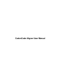
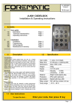
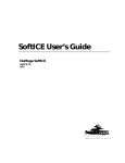
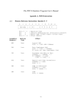
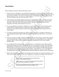
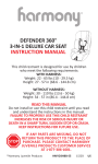
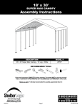
Installation Instructions
For Hunter Ceiling Fan Light Kits
Aurora Style
Preparing for Installation
CAUTIONS
·
·
1. Unassemble the fan switch housing as shown in
Figure 1.
Read entire text carefully before
beginning installation and save these
instructions.
To reduce the risk of electrical shock,
install this light kit only on listed Hunter
ceiling fans type A through Z.
2. Disconnect the upper and lower plug connectors
between the upper switch housing and lower
switch housing.
Note: Do not discard any parts. You will need to
replace it if you remove the light fixture in the
future.
Upper Switch
Housing
WARNINGS
·
·
·
To avoid possible electrical shock, before
installing light fixtures, disconnect power
by turning off the circuit breakers both
to the outlet box and to its associated wall
switch location. If you cannot lock the
circuit breakers in theoff position,
securely fasten a prominent warning
device, such as a tag, to the service panel.
Connect house wiring to the fan before
attaching the light fixture to the fan.
All wiring must be in accordance with
national and local electrical codes. If you
are unfamiliar with wiring, you should use
a qualified electrician. Professional
installation is recommended.
© 2003 Hunter Fan Company
Switch
Housing
Assembly
Screws
Lower
Switch
Housing
Switch
Housing
Cover
Plate
Plug Button
Switch Housing
Assembly Screws
Figure 1 - Unassembling the fan switch housing
1
41558-01 3-6-2003
Installing the Light Fixture
1. Insert the black wire and white wire from the
light kit assembly through the hole in the bottom
of the lower switch housing. Refer to Figures 2
and 3.
2. Securely tighten the light kit assembly into the
bottom of the lower switch housing. Refer to
Figure 3.
3. Install the nut and washer onto the end of the
light kit assembly inside of the lower switch
housing. Securely tighten the nut and washer.
Insert and tighten the two #6-32 sems light
fixture mounting screws. Refer to Figure 3.
4. Using the wire nuts on the two light kit wires in
the lower switch housing, connect the black wire
from the light kit assembly to the black/white
wire from the lower switch housing and connect
the white wire from the light kit assembly to the
white wire from the lower switch housing.
5. Reconnect the upper plug connector from the
upper switch housing to the lower plug connector
in the lower switch housing. Refer to Figure 4.
Note: Both plug connectors are polarized and will
only fit together one way. Make sure that both
connectors are properly aligned before connecting
them together. Incorrect connection could cause
improper operation and damage to the product.
6. Align the holes in the upper switch housing and
the lower switch housing. Securely tighten the
three switch housing screws assembly screws.
Refer to Figure 1 and 4.
Lower
Switch
Housing
Light Kit
Assembly
Figure 2 - Assembling
the Light Kit
Figure 3 - Attached Light
Kit Assembly
Upper
Switch
Housing
Upper Plug
Connector
Lower Plug
Connector
Figure 4 - Connecting the Plug Connectors
41558-01 3-6-2003
2
© 2003 Hunter Fan Company
Installing Globes and Bulbs
Thread the fan switch pull chain through the
grommetted hole in the light fixture bracket. Unfasten
the extra chain looped through the hole in the in the
lower mounting cap and attach it to the fan switch
pull chain. Repeat for light switch pull chain.
Refer to Figures 5, 6 and 7.
1. Install bulbs. Use 60W Max, A-15 bulbs.
2. Thread the fan switch pull chain through the hole in
the metal disk.
Hole in Lower
Mounting Cap
3. Place globe on pipe until flush against metal disk.
4. Thread the light switch pull chain through the large
center opening of the globe.
5. Thread the fan switch pull chain through the small
center opening in the globe.
Figure 6 - Attaching Fan Switch Pull Chain Extension
6. Place the cover plate up against the underside of
the globe. Pass light and fan switch pull chains
through the appropriate holes.
Fan Switch
Pull Chain
7. Thread the light switch pull chain through the
finial and screw the cap onto the pipe end until
tight.
Bulb
Socket
Pipe
Metal Disk
Globe
Light
Switch Pull
Chain
Grommetted
Hole
Lower Mounting Cap
Extra Chains
Figure 5 - Threading Fan Switch Pull Chain through
Grommet
Cover Plate
Finial
Figure 7 - Aurora Fixtures
Hunter Fan Company
2500 Frisco Avenue
Memphis, Tennessee 38125
U nited States of America
© 2003 Hunter Fan Company
3
41558-01 3-6-2003