1
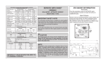
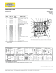
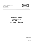
INSTRUCTIONS
2020
Publication No. 132
January 1985
Hubbell Industrial Controls, Inc.
Repl.: January 1984
EUCLID™ PBP PENDANT
PUSHBUTTON STATIONS
ASSEMBLY AND PARTS INFORMATION
Step #1 Position hanger bracket (Item 1) as required and
tighten locking nut 1/3 turn past finger tight.
Step #2 Pilot light assembly (Item 2) if used -- push out plug
(P/N 28338) from rear. Insert light assembly. Insert
pilot light legend plate. Install locking ring.
Step #3 *Install button assembly (not Pictorially shown).
Align keying tabs and holes and press push button
assembly into terminal boards. Tighten hold down
screws. (Not used on MS2 & MS5).
AVOID
OVERTIGTENING
Step #4 *Install terminal board with button assembly working
from top to bottom. Use 8-32 x 1/2" (P/N 47661098) "sems" screws (Item 4) where single thickness
terminal board is fastened. Observe "Top" marking
on each board. AVOID OVERTIGHTENING
Step #5 *Use 8-32 x 5/8" (P/N 47661-100) "sems" screws
(Item 5) where two terminal boards overlap. AVOID
OVERTIGHTENING
Step #6 Use 8-32 x
(Item 6) to
CAUTION:
SCREWS.
12 in. lbs.
allowed.
1/2" (P/N 47243-059) pan head screws
install button guards and back cover.
DO NOT OVERTIGHTEN THESE
Recommended torque is 10 in. lbs. To
Maximum. A slight rubber bulging is
* Where direct wired push buttons are used,
Steps #3, #4, & #5 do not apply.
PILOT LIGHTS
DESCRIPTION
Pilot Light 120v 60 Hz AC
Pilot Light 240v 60 Hz AC
CATALOG
NUMBER
LAMP
PART NO.
PL1
PL2
57465-015
57465-015
DESCRIPTION
Pilot Light 120V DC
Pilot Light 240v DC
CATALOG
NUMBER
LAMP
PART NO.
PL3
PL4
57465-043
57465-007
CONTACT
INTERRUPTING
RATINGS
ENCLOSURE DIMENSIONS
APPROX. WT.
ASSEMBLED
MOTION
A
1*
2 Buttons
7- /8"
7
2- /2 lbs.
2
4 Buttons
13- /16"
11
4- /2 lbs.
3
6 Buttons
18"
4
8 Buttons
22- /16"
5
1
E2
A.C.
35% PF
120v
240v
6A
3A
1
E4
D.C.
IND
125v
250v
.4A
.2A
5- /2 lbs.
1
E6
7 lbs.
E8
* Pilot light is not available on 1 motion enclosure
SYMBOL
PLUG-IN*
MOMENTARY
N.O.
---
DIRECT
WIRED**
CAT.
NO.
--
PG1
MOMENTARY
N.O.
MAINTAINED
TYPICAL
APPLICATIONS
DW1
DWS
Start-Stop
functions
MOMENTARY
N.O. & N.C.
--
PG2
MAINTAINED
N.O. & N.C.
--
PG3
Auxiliary
functions
MAINTAINED
MOMENTARY
LIFT/DROP
--
PG4 †
MOMENTARY
MAINTAINED
--
PG5 †
--
PG6 •
A.C.
35% PF
120v
240v
6A
3A
D.C.
IND.
125v
250v
1.1A
.55A
DESCRIPTION
SYMBOL
PLUG-IN*
CAT.
NO.
TYPICAL
APPLICATION
Crane control:
trolley, bridge
& hoist, etc.
Interlocking,
crane control
MOMEMTARY
START-STOP
RESET-STOP
SINGLE SPEED
DOUBLE BREAK
MULTI-SPEED INSERT
SINGLE SPEED INSERT
DESCRIPTION
MULTI-SPEED
SINGLE BREAK
CATALOG NO.
USED TO A
MAXIMUM
OF THREE
SPEED
POINTS
MS2
For
multispeed
functions
MS5
For
multispeed
functions
Magnet
control
Used as a
toggle switch
and for startstop functions
Start-stop onoff functions
USED TO A
MAXIMUM
OF FIVE
SPEED
POINTS
Stop-start offon functions
MOMENTARY
STOP-START
STOP-RESET
--
PG7 •
† PG4 and PG5 inserts have one button maintained and one button momentary.
* Terminal Base Cat. TB2 required for each plug-in insert PG1, PG2, PG3, PG4, PG5,
PG6, PG7 and MS2. Terminal Base TB5 required for MS5 insert.
**Terminal Base not required with direct wired unit.
• "Power On-Off" buttons recommended to comply with provisions of NEMA ICS 3-442.15
Hubbell Industrial Controls, Inc.
A subsidiary of Hubbell Incorporated
4301 Cheyenne Dr., Archdale, NC. 27262
Telephone (336) 434-2800 • FAX (336) 434-2803
http://www.hubbell-icd.com
[email protected]