1
HP VMA SAN Gateway
Installation and User Guide
Document Number: AM456-9007B Rev 02
May 2012
LEGAL NOTICES
Copyright 2011, 2012 Hewlett-Packard Development Company, L.P.
The information contained herein is subject to change without notice. The only warranties for HP products and
services are set forth in the express warranty statements accompanying such products and services. Nothing
herein should be construed as constituting an additional warranty. HP shall not be liable for technical or editorial
errors or omissions contained herein.
Copyright © 2010-2012 Violin Memory, Inc. All rights reserved.
Violin Memory, Violin Technologies, Violin and Design, Violin, vSHARE, vCACHE, and Flash Forward are
trademarks, registered trademarks or service marks of Violin Memory, Inc. ("Violin") in the United States and
other countries.
All other brands, product names, company names, trademarks, and service marks are the properties of their respective owners.
This document and the associated software product are protected by copyright and international treaties, and are
the confidential and proprietary information and property of Violin, and are distributed only under license from
Violin, including confidentiality restrictions and other restrictions on use, copying, redistribution and reverse
engineering. Unless otherwise agreed by Violin in writing, Violin's standard end user license agreement shall
apply, which may be reviewed at www.violin-memory.com/legal. No part of this document may be reproduced,
distributed, adapted or translated without prior written permission of Violin, except as expressly permitted under
the license from Violin. The associated software product may include, access or otherwise operate, interface or
be delivered with third party software or other applications or copyrighted materials, which are copyrighted and
licensed by Violin suppliers. Such third party materials and licenses are identified in this document and/or at
www.violin-memory.com/legal.
Violin assumes no responsibility for any typographical, technical or other error or omission in this document.
Violin reserves the right to periodically change the information contained in this document, but Violin makes
no commitment to provide any such changes, updates, enhancements or other additions in a timely manner or
at all.
The only warranties for Violin software, hardware and other products and services are set forth in the express
warranty statements accompanying such products and services. Nothing herein should be construed as constituting an additional warranty.
THIS DOCUMENT (INCLUDING ANY EXAMPLES AND OTHER INFORMATION CONTAINED HEREIN) IS MADE AVAILABLE "AS IS" WITHOUT REPRESENTATION OR WARRANTY OF ANY KIND.
VIOLIN MAKES NO REPRESENTATION OR WARRANTY IN THIS DOCUMENT REGARDING ANY
ASSOCIATED SOFTWARE OR ANY OTHER VIOLIN OR THIRD PARTY HARDWARE, SOFTWARE
OR OTHER PRODUCTS OR SERVICES REFERENCED HEREIN. TO THE FULLEST EXTENT PERMITTED BY LAW, VIOLIN (FOR ITSELF AND ITS LICENSORS AND OTHER THIRD PARTIES IDENTIFIED HEREIN) HEREBY DISCLAIMS ALL REPRESENTATIONS AND WARRANTIES, WHETHER
EXPRESS OR IMPLIED, ORAL OR WRITTEN, WITH RESPECT TO THE FOREGOING, INCLUDING
WITHOUT LIMITATION, ALL IMPLIED WARRANTIES OF TITLE, NON-INFRINGEMENT, QUIET
ENJOYMENT, ACCURACY, INTEGRATION, MERCHANTABILITY OR FITNESS FOR ANY PARTICULAR PURPOSE.
2
HP VMA SAN Gateway Installation and User Guide
AM456-9007B Rev 02
IN NO EVENT SHALL VIOLIN (OR ITS LICENSORS OR ANY OTHER THIRD PARTY IDENTIFIED
HEREIN) BE LIABLE CONCERNING ANY USE OF THIS DOCUMENT, REGARDLESS OF THE FORM
OF ANY CLAIM OR ACTION (WHETHER IN CONTRACT, NEGLIGENCE, STRICT LIABILITY OR
OTHERWISE), FOR ANY DIRECT, INDIRECT, PUNITIVE, INCIDENTAL, RELIANCE, SPECIAL, EXEMPLARY OR CONSEQUENTIAL DAMAGES, INCLUDING WITHOUT LIMITATION, ANY LOSS OF
DATA, LOSS OR INTERRUPTION OF USE, COST OF PROCURING SUBSTITUTE TECHNOLOGIES,
GOODS OR SERVICES, OR LOSS OF BUSINESS, REVENUES, PROFITS OR GOODWILL, EVEN IF ADVISED OF THE POSSIBILITY OF SUCH DAMAGES.
Violin Memory, Inc.
685 Clyde Avenue
Mountain View, CA 94043USA
Compliance notices and information can be found in Compliance Information on page 12.
DISCLAIMER
Portions of this document are intended solely as an outline of methodologies to be followed during
the installation, set-up, and maintenance of HP equipment. It is not intended as a step-by-step guide or
a complete set of all necessary and sufficient procedures.
While every effort has been made to ensure that this document is complete and accurate at the time of
publication, the information that it contains is subject to change. HP is not responsible for any
additions to or alterations of the original document. This document is intended as a general guide
only. It has not been tested for all possible applications, and it may not be complete or accurate for
some situations.
Users of this document are urged to heed warnings interspersed throughout the document, such as
service disruption warnings.
TRADEMARKS
•
Violin, Violin memory, and the Violin logo are trademarks of Violin Memory
•
Linux is a registered trademark of Linus Torvalds.
•
Intel is a registered trademark of Intel Corporation in the United States and other countries.
•
Windows is a registered trademark of Microsoft Corporation in the United States and other countries.
4
HP VMA SAN Gateway Installation and User Guide
AM456-9007B Rev 02
Table of Contents
List of Figures . . . . . . . . . . . . . . . . . . . . . . . . . . . . . . . . . . . . . . . . . . . . . . . . . . . . . . . . . . . . . . . . . . . . . . . . . . . . . . . . . . . . . . . . . . . . . . 9
Preface . . . . . . . . . . . . . . . . . . . . . . . . . . . . . . . . . . . . . . . . . . . . . . . . . . . . . . . . . . . . . . . . . . . . . . . . . . . . . . . . . . . . . . . . . . . . . . . . . . . 11
CHAPTER 1. HP VMA SAN Gateway Overview . . . . . . . . . . . . . . . . . . . . . . . . . . . . . . . . . . . . . . . . . . . . . . . . . . . . . . . . . . . . . . . 17
Introduction to the HP VMA SAN Gateway . . . . . . . . . . . . . . . . . . . . . . . . . . . . . . . . . . . . . . . . . . . . . . . . . . . . . . . . . .17
vSHARE Architecture . . . . . . . . . . . . . . . . . . . . . . . . . . . . . . . . . . . . . . . . . . . . . . . . . . . . . . . . . . . . . . . . . . . . . . . . . . . .18
vCLUSTER Architecture . . . . . . . . . . . . . . . . . . . . . . . . . . . . . . . . . . . . . . . . . . . . . . . . . . . . . . . . . . . . . . . . . . . . . . . . .20
CHAPTER 2. Installing and Upgrading the HP VMA SAN Gateway . . . . . . . . . . . . . . . . . . . . . . . . . . . . . . . . . . . . . . . . . . . . . . 23
Deployment Overview . . . . . . . . . . . . . . . . . . . . . . . . . . . . . . . . . . . . . . . . . . . . . . . . . . . . . . . . . . . . . . . . . . . . . . . . . . . .23
HP VMA SAN Gateway Installation . . . . . . . . . . . . . . . . . . . . . . . . . . . . . . . . . . . . . . . . . . . . . . . . . . . . . . . . . . . . . . . .27
CHAPTER 3. Configuring and Managing Clusters . . . . . . . . . . . . . . . . . . . . . . . . . . . . . . . . . . . . . . . . . . . . . . . . . . . . . . . . . . . . . 37
vCLUSTER Overview . . . . . . . . . . . . . . . . . . . . . . . . . . . . . . . . . . . . . . . . . . . . . . . . . . . . . . . . . . . . . . . . . . . . . . . . . . . .37
HP VMA SAN Gateway Cluster Configuration . . . . . . . . . . . . . . . . . . . . . . . . . . . . . . . . . . . . . . . . . . . . . . . . . . . . . . .40
HP VMA SAN Gateway Cluster Management . . . . . . . . . . . . . . . . . . . . . . . . . . . . . . . . . . . . . . . . . . . . . . . . . . . . . . . .53
Configuration File Management. . . . . . . . . . . . . . . . . . . . . . . . . . . . . . . . . . . . . . . . . . . . . . . . . . . . . . . . . . . . . . . . . . . .57
User Management . . . . . . . . . . . . . . . . . . . . . . . . . . . . . . . . . . . . . . . . . . . . . . . . . . . . . . . . . . . . . . . . . . . . . . . . . . . . . . .63
Software Upgrades . . . . . . . . . . . . . . . . . . . . . . . . . . . . . . . . . . . . . . . . . . . . . . . . . . . . . . . . . . . . . . . . . . . . . . . . . . . . . . .64
CHAPTER 4. Configuring vSHARE . . . . . . . . . . . . . . . . . . . . . . . . . . . . . . . . . . . . . . . . . . . . . . . . . . . . . . . . . . . . . . . . . . . . . . . . . 65
Understanding vSHARE . . . . . . . . . . . . . . . . . . . . . . . . . . . . . . . . . . . . . . . . . . . . . . . . . . . . . . . . . . . . . . . . . . . . . . . . . .65
Configuring Storage Containers. . . . . . . . . . . . . . . . . . . . . . . . . . . . . . . . . . . . . . . . . . . . . . . . . . . . . . . . . . . . . . . . . . . .70
Configuring Target Ports . . . . . . . . . . . . . . . . . . . . . . . . . . . . . . . . . . . . . . . . . . . . . . . . . . . . . . . . . . . . . . . . . . . . . . . . .73
Configuring Initiator Groups . . . . . . . . . . . . . . . . . . . . . . . . . . . . . . . . . . . . . . . . . . . . . . . . . . . . . . . . . . . . . . . . . . . . . .74
Creating LUNs . . . . . . . . . . . . . . . . . . . . . . . . . . . . . . . . . . . . . . . . . . . . . . . . . . . . . . . . . . . . . . . . . . . . . . . . . . . . . . . . . .76
Exporting LUNs . . . . . . . . . . . . . . . . . . . . . . . . . . . . . . . . . . . . . . . . . . . . . . . . . . . . . . . . . . . . . . . . . . . . . . . . . . . . . . . . .80
Optimizing Connectivity to Storage Arrays for Windows . . . . . . . . . . . . . . . . . . . . . . . . . . . . . . . . . . . . . . . . . . . . . . .82
AM456-9007B Rev 02
HP VMA SAN Gateway Installation and User Guide
5
Deploying vSHARE in a High Availability Configuration . . . . . . . . . . . . . . . . . . . . . . . . . . . . . . . . . . . . . . . . . . . . . . 82
CHAPTER 5. Operating vSHARE . . . . . . . . . . . . . . . . . . . . . . . . . . . . . . . . . . . . . . . . . . . . . . . . . . . . . . . . . . . . . . . . . . . . . . . . . . . 89
Verifying Connections and Performance . . . . . . . . . . . . . . . . . . . . . . . . . . . . . . . . . . . . . . . . . . . . . . . . . . . . . . . . . . . . 89
Block Storage Media Management . . . . . . . . . . . . . . . . . . . . . . . . . . . . . . . . . . . . . . . . . . . . . . . . . . . . . . . . . . . . . . . . . 92
vSHARE Block Storage Management Commands . . . . . . . . . . . . . . . . . . . . . . . . . . . . . . . . . . . . . . . . . . . . . . . . . . . 102
Managing Block Storage in the VMA Web Interface . . . . . . . . . . . . . . . . . . . . . . . . . . . . . . . . . . . . . . . . . . . . . . . . . 104
APPENDIX A:. Command Line Interface . . . . . . . . . . . . . . . . . . . . . . . . . . . . . . . . . . . . . . . . . . . . . . . . . . . . . . . . . . . . . . . . . . . 113
Using the Command Line Interface . . . . . . . . . . . . . . . . . . . . . . . . . . . . . . . . . . . . . . . . . . . . . . . . . . . . . . . . . . . . . . . 113
CLI Command Descriptions . . . . . . . . . . . . . . . . . . . . . . . . . . . . . . . . . . . . . . . . . . . . . . . . . . . . . . . . . . . . . . . . . . . . . 120
General Configuration Commands . . . . . . . . . . . . . . . . . . . . . . . . . . . . . . . . . . . . . . . . . . . . . . . . . . . . . . . . . . . . . . . . 122
Network Configuration Commands . . . . . . . . . . . . . . . . . . . . . . . . . . . . . . . . . . . . . . . . . . . . . . . . . . . . . . . . . . . . . . . 148
Additional CLI Commands . . . . . . . . . . . . . . . . . . . . . . . . . . . . . . . . . . . . . . . . . . . . . . . . . . . . . . . . . . . . . . . . . . . . . . 152
Media Management Commands . . . . . . . . . . . . . . . . . . . . . . . . . . . . . . . . . . . . . . . . . . . . . . . . . . . . . . . . . . . . . . . . . . 167
vSHARE Commands. . . . . . . . . . . . . . . . . . . . . . . . . . . . . . . . . . . . . . . . . . . . . . . . . . . . . . . . . . . . . . . . . . . . . . . . . . . . 170
Quick Reference to Commands . . . . . . . . . . . . . . . . . . . . . . . . . . . . . . . . . . . . . . . . . . . . . . . . . . . . . . . . . . . . . . . . . . . 173
APPENDIX B:. VMA Web Interface Reference . . . . . . . . . . . . . . . . . . . . . . . . . . . . . . . . . . . . . . . . . . . . . . . . . . . . . . . . . . . . . . . 177
Understanding the VMA Web Interface . . . . . . . . . . . . . . . . . . . . . . . . . . . . . . . . . . . . . . . . . . . . . . . . . . . . . . . . . . . . 177
Login and Logout . . . . . . . . . . . . . . . . . . . . . . . . . . . . . . . . . . . . . . . . . . . . . . . . . . . . . . . . . . . . . . . . . . . . . . . . . . . . . . 183
Cluster Management. . . . . . . . . . . . . . . . . . . . . . . . . . . . . . . . . . . . . . . . . . . . . . . . . . . . . . . . . . . . . . . . . . . . . . . . . . . . 184
Administration Pages . . . . . . . . . . . . . . . . . . . . . . . . . . . . . . . . . . . . . . . . . . . . . . . . . . . . . . . . . . . . . . . . . . . . . . . . . . . 192
Tools Pages. . . . . . . . . . . . . . . . . . . . . . . . . . . . . . . . . . . . . . . . . . . . . . . . . . . . . . . . . . . . . . . . . . . . . . . . . . . . . . . . . . . . 202
Help Pages . . . . . . . . . . . . . . . . . . . . . . . . . . . . . . . . . . . . . . . . . . . . . . . . . . . . . . . . . . . . . . . . . . . . . . . . . . . . . . . . . . . . 204
vSHARE Block Storage Management. . . . . . . . . . . . . . . . . . . . . . . . . . . . . . . . . . . . . . . . . . . . . . . . . . . . . . . . . . . . . . 205
APPENDIX C:. VMA Utilities . . . . . . . . . . . . . . . . . . . . . . . . . . . . . . . . . . . . . . . . . . . . . . . . . . . . . . . . . . . . . . . . . . . . . . . . . . . . . 213
Understanding the VMA Utilities . . . . . . . . . . . . . . . . . . . . . . . . . . . . . . . . . . . . . . . . . . . . . . . . . . . . . . . . . . . . . . . . . 213
6
AM456-9007B Rev 02
HP VMA SAN Gateway Installation and User Guide
VMA Utilities Reference . . . . . . . . . . . . . . . . . . . . . . . . . . . . . . . . . . . . . . . . . . . . . . . . . . . . . . . . . . . . . . . . . . . . . . . . .214
APPENDIX D:. Standard System Configurations . . . . . . . . . . . . . . . . . . . . . . . . . . . . . . . . . . . . . . . . . . . . . . . . . . . . . . . . . . . . . 233
Single Gateway with 1–2 3000-Series Arrays, Non-Redundant . . . . . . . . . . . . . . . . . . . . . . . . . . . . . . . . . . . . . . . . .233
Dual Gateways with 1–2 3000-Series Arrays, Highly Available . . . . . . . . . . . . . . . . . . . . . . . . . . . . . . . . . . . . . . . . .233
Multiple Gateways with 1–2 3000-Series Arrays Each, Highly Available . . . . . . . . . . . . . . . . . . . . . . . . . . . . . . . . .235
. . . . . . . . . . . . . . . . . . . . . . . . . . . . . . . . . . . . . . . . . . . . . . . . . . . . . . . . . . . . . . . . . . . . . . . . . . . . . . . . . . . . . . . . . . . . . .237
APPENDIX E:. SNMP Usage for HP VMA SAN Gateway Version G5.1.x . . . . . . . . . . . . . . . . . . . . . . . . . . . . . . . . . . . . . . . . 239
SNMP Configuration on the HP VMA SAN Gateway . . . . . . . . . . . . . . . . . . . . . . . . . . . . . . . . . . . . . . . . . . . . . . . . .240
Traps . . . . . . . . . . . . . . . . . . . . . . . . . . . . . . . . . . . . . . . . . . . . . . . . . . . . . . . . . . . . . . . . . . . . . . . . . . . . . . . . . . . . . . . . .240
Trap Information Table . . . . . . . . . . . . . . . . . . . . . . . . . . . . . . . . . . . . . . . . . . . . . . . . . . . . . . . . . . . . . . . . . . . . . . . . .243
New Trap MIB Objects . . . . . . . . . . . . . . . . . . . . . . . . . . . . . . . . . . . . . . . . . . . . . . . . . . . . . . . . . . . . . . . . . . . . . . . . . .255
APPENDIX F:. Compliance Information . . . . . . . . . . . . . . . . . . . . . . . . . . . . . . . . . . . . . . . . . . . . . . . . . . . . . . . . . . . . . . . . . . . . 267
Regulatory Model Number . . . . . . . . . . . . . . . . . . . . . . . . . . . . . . . . . . . . . . . . . . . . . . . . . . . . . . . . . . . . . . . . . . . . . . .268
Installation Conditions . . . . . . . . . . . . . . . . . . . . . . . . . . . . . . . . . . . . . . . . . . . . . . . . . . . . . . . . . . . . . . . . . . . . . . . . . .268
Network Connected Equipment . . . . . . . . . . . . . . . . . . . . . . . . . . . . . . . . . . . . . . . . . . . . . . . . . . . . . . . . . . . . . . . . . . .268
Electrostatic Discharge (ESD) Precautions . . . . . . . . . . . . . . . . . . . . . . . . . . . . . . . . . . . . . . . . . . . . . . . . . . . . . . . . . .268
Lithium Battery Caution . . . . . . . . . . . . . . . . . . . . . . . . . . . . . . . . . . . . . . . . . . . . . . . . . . . . . . . . . . . . . . . . . . . . . . . . .269
Cabinet Safety Precautions . . . . . . . . . . . . . . . . . . . . . . . . . . . . . . . . . . . . . . . . . . . . . . . . . . . . . . . . . . . . . . . . . . . . . . .269
Disposal of Waste Equipment by Users in Private Households in the European Union. . . . . . . . . . . . . . . . . . . . . .269
Perchlorate Material - Special Handling May Apply . . . . . . . . . . . . . . . . . . . . . . . . . . . . . . . . . . . . . . . . . . . . . . . . . .270
European Union RFI Statement . . . . . . . . . . . . . . . . . . . . . . . . . . . . . . . . . . . . . . . . . . . . . . . . . . . . . . . . . . . . . . . . . . .270
USA Radio Frequency Interference FCC Notice . . . . . . . . . . . . . . . . . . . . . . . . . . . . . . . . . . . . . . . . . . . . . . . . . . . . .270
Japan Radio Frequency Interference VCCI . . . . . . . . . . . . . . . . . . . . . . . . . . . . . . . . . . . . . . . . . . . . . . . . . . . . . . . . .271
Korea RFI Statement. . . . . . . . . . . . . . . . . . . . . . . . . . . . . . . . . . . . . . . . . . . . . . . . . . . . . . . . . . . . . . . . . . . . . . . . . . . .271
Canada RFI Statement . . . . . . . . . . . . . . . . . . . . . . . . . . . . . . . . . . . . . . . . . . . . . . . . . . . . . . . . . . . . . . . . . . . . . . . . . .271
Australia C-Tick Label . . . . . . . . . . . . . . . . . . . . . . . . . . . . . . . . . . . . . . . . . . . . . . . . . . . . . . . . . . . . . . . . . . . . . . . . . .271
AM456-9007B Rev 02
HP VMA SAN Gateway Installation and User Guide
7
Taiwan BSMI Statement . . . . . . . . . . . . . . . . . . . . . . . . . . . . . . . . . . . . . . . . . . . . . . . . . . . . . . . . . . . . . . . . . . . . . . . . 271
Index. . . . . . . . . . . . . . . . . . . . . . . . . . . . . . . . . . . . . . . . . . . . . . . . . . . . . . . . . . . . . . . . . . . . . . . . . . . . . . . . . . . . . . . . . . . . . . . . . . . . 273
8
AM456-9007B Rev 02
HP VMA SAN Gateway Installation and User Guide
List of Figures
Figure 1.1 HP VMA SAN Gateway System. . . . . . . . . . . . . . . . . . . . . . . . . . . . . . . . . . . . . . . . . . . . . . . . . . . . . . . . . . . 17
Figure 2.1 HP VMA SAN Gateway Deployment Flowchart. . . . . . . . . . . . . . . . . . . . . . . . . . . . . . . . . . . . . . . . . . . . . . . 24
Figure 2.2 HP VMA SAN Gateway Back Pane . . . . . . . . . . . . . . . . . . . . . . . . . . . . . . . . . . . . . . . . . . . . . . . . . . . . . . . . 29
Figure 2.3 HP VMA SAN Gateway and Memory Array Back Panels . . . . . . . . . . . . . . . . . . . . . . . . . . . . . . . . . . . . . . . 31
Figure 2.4 HP VMA SAN Gateway Power Supplies. . . . . . . . . . . . . . . . . . . . . . . . . . . . . . . . . . . . . . . . . . . . . . . . . . . . . 32
Figure 2.5 Network Interfaces . . . . . . . . . . . . . . . . . . . . . . . . . . . . . . . . . . . . . . . . . . . . . . . . . . . . . . . . . . . . . . . . . . . . . . 33
Figure 2.6 HP VMA SAN Gateway Network Connectivity . . . . . . . . . . . . . . . . . . . . . . . . . . . . . . . . . . . . . . . . . . . . . . . 34
Figure 4.1 vSHARE System Architecture . . . . . . . . . . . . . . . . . . . . . . . . . . . . . . . . . . . . . . . . . . . . . . . . . . . . . . . . . . . . . 66
Figure 4.2 HP VMA SAN Gateway Deployment Flowchart. . . . . . . . . . . . . . . . . . . . . . . . . . . . . . . . . . . . . . . . . . . . . . . 68
Figure 4.3 vSHARE Deployment Flowchart . . . . . . . . . . . . . . . . . . . . . . . . . . . . . . . . . . . . . . . . . . . . . . . . . . . . . . . . . . . 69
Figure 4.4 vSHARE High Availability Configuration. . . . . . . . . . . . . . . . . . . . . . . . . . . . . . . . . . . . . . . . . . . . . . . . . . . . 83
Figure 4.5 Mapping Multiple HA Paths to a Single Device Image will need to be redone. . . . . . . . . . . . . . . . . . . . . . . . 86
Figure 5.1 LUN Status Page . . . . . . . . . . . . . . . . . . . . . . . . . . . . . . . . . . . . . . . . . . . . . . . . . . . . . . . . . . . . . . . . . . . . . . 105
Figure 5.2 LUN Management Page . . . . . . . . . . . . . . . . . . . . . . . . . . . . . . . . . . . . . . . . . . . . . . . . . . . . . . . . . . . . . . . . . 106
Figure 5.3 Initiator Management Page. . . . . . . . . . . . . . . . . . . . . . . . . . . . . . . . . . . . . . . . . . . . . . . . . . . . . . . . . . . . . . . 109
Figure 5.4 Target Management Page . . . . . . . . . . . . . . . . . . . . . . . . . . . . . . . . . . . . . . . . . . . . . . . . . . . . . . . . . . . . . . . . 110
Figure B.1 Web Interface Organization . . . . . . . . . . . . . . . . . . . . . . . . . . . . . . . . . . . . . . . . . . . . . . . . . . . . . . . . . . . . . . 178
Figure B.2 Login Page . . . . . . . . . . . . . . . . . . . . . . . . . . . . . . . . . . . . . . . . . . . . . . . . . . . . . . . . . . . . . . . . . . . . . . . . . . . 183
Figure B.3 Logout Page . . . . . . . . . . . . . . . . . . . . . . . . . . . . . . . . . . . . . . . . . . . . . . . . . . . . . . . . . . . . . . . . . . . . . . . . . . 184
Figure B.4 Status Page . . . . . . . . . . . . . . . . . . . . . . . . . . . . . . . . . . . . . . . . . . . . . . . . . . . . . . . . . . . . . . . . . . . . . . . . . . . 185
Figure B.5 Board Status Page . . . . . . . . . . . . . . . . . . . . . . . . . . . . . . . . . . . . . . . . . . . . . . . . . . . . . . . . . . . . . . . . . . . . . 186
Figure B.6 Board Status Page - Raid Group . . . . . . . . . . . . . . . . . . . . . . . . . . . . . . . . . . . . . . . . . . . . . . . . . . . . . . . . . . 187
Figure B.7 Gateways Page . . . . . . . . . . . . . . . . . . . . . . . . . . . . . . . . . . . . . . . . . . . . . . . . . . . . . . . . . . . . . . . . . . . . . . . . 188
Figure B.8 Gateway Details Page . . . . . . . . . . . . . . . . . . . . . . . . . . . . . . . . . . . . . . . . . . . . . . . . . . . . . . . . . . . . . . . . . . 189
Figure B.9 Alerts Page . . . . . . . . . . . . . . . . . . . . . . . . . . . . . . . . . . . . . . . . . . . . . . . . . . . . . . . . . . . . . . . . . . . . . . . . . . . 190
Figure B.10 Logs Page. . . . . . . . . . . . . . . . . . . . . . . . . . . . . . . . . . . . . . . . . . . . . . . . . . . . . . . . . . . . . . . . . . . . . . . . . . . 191
Figure B.11 Versions Page. . . . . . . . . . . . . . . . . . . . . . . . . . . . . . . . . . . . . . . . . . . . . . . . . . . . . . . . . . . . . . . . . . . . . . . . 192
Figure B.12 Cluster Administration Page . . . . . . . . . . . . . . . . . . . . . . . . . . . . . . . . . . . . . . . . . . . . . . . . . . . . . . . . . . . . 193
Figure B.13 Network Settings Page . . . . . . . . . . . . . . . . . . . . . . . . . . . . . . . . . . . . . . . . . . . . . . . . . . . . . . . . . . . . . . . . . 194
Figure B.14 DNS Settings Page. . . . . . . . . . . . . . . . . . . . . . . . . . . . . . . . . . . . . . . . . . . . . . . . . . . . . . . . . . . . . . . . . . . . 195
Figure B.15 NTP Settings Page . . . . . . . . . . . . . . . . . . . . . . . . . . . . . . . . . . . . . . . . . . . . . . . . . . . . . . . . . . . . . . . . . . . . 196
Figure B.16 Web Administration Page . . . . . . . . . . . . . . . . . . . . . . . . . . . . . . . . . . . . . . . . . . . . . . . . . . . . . . . . . . . . . . 197
Figure B.17 Feature Licenses Page . . . . . . . . . . . . . . . . . . . . . . . . . . . . . . . . . . . . . . . . . . . . . . . . . . . . . . . . . . . . . . . . . 198
Figure B.18 Users Page . . . . . . . . . . . . . . . . . . . . . . . . . . . . . . . . . . . . . . . . . . . . . . . . . . . . . . . . . . . . . . . . . . . . . . . . . . 199
Figure B.19 Alert Recipients Page. . . . . . . . . . . . . . . . . . . . . . . . . . . . . . . . . . . . . . . . . . . . . . . . . . . . . . . . . . . . . . . . . . 200
Figure B.20 Call Home Page . . . . . . . . . . . . . . . . . . . . . . . . . . . . . . . . . . . . . . . . . . . . . . . . . . . . . . . . . . . . . . . . . . . . . . 202
Figure B.21 Upgrade Page . . . . . . . . . . . . . . . . . . . . . . . . . . . . . . . . . . . . . . . . . . . . . . . . . . . . . . . . . . . . . . . . . . . . . . . . 203
Figure B.22 Diagnostics Page . . . . . . . . . . . . . . . . . . . . . . . . . . . . . . . . . . . . . . . . . . . . . . . . . . . . . . . . . . . . . . . . . . . . . 204
Figure B.23 LUN Status Page . . . . . . . . . . . . . . . . . . . . . . . . . . . . . . . . . . . . . . . . . . . . . . . . . . . . . . . . . . . . . . . . . . . . . 205
Figure B.24 LUN Management Page. . . . . . . . . . . . . . . . . . . . . . . . . . . . . . . . . . . . . . . . . . . . . . . . . . . . . . . . . . . . . . . . 206
Figure B.25 Initiator Management Page . . . . . . . . . . . . . . . . . . . . . . . . . . . . . . . . . . . . . . . . . . . . . . . . . . . . . . . . . . . . . 209
Figure B.26 Target Management Page . . . . . . . . . . . . . . . . . . . . . . . . . . . . . . . . . . . . . . . . . . . . . . . . . . . . . . . . . . . . . . 211
Figure D.1 Single Gateway with 1–2 3000-Series Arrays, Non-Redundant . . . . . . . . . . . . . . . . . . . . . . . . . . . . . . . . . . 233
Figure D.2 Dual gateway – Redundant gateway pair with 1 to 2 VMA 3200 series arrays, highly available . . . . . . . . 234
AM456-9007B Rev 02
HP VMA SAN Gateway Installation and User Guide
9
Figure D.3 Multiple redundant gateways with 1 to 2 VMA 3200 Series arrays, each highly available. . . . . . . . . . . . . . 237
Figure F.1 Australian C-Tick Label . . . . . . . . . . . . . . . . . . . . . . . . . . . . . . . . . . . . . . . . . . . . . . . . . . . . . . . . . . . . . . . . . 271
10
AM456-9007B Rev 02
HP VMA SAN Gateway Installation and User Guide
Preface
This document describes how to install, configure, and manage the VMA-series
SAN Gateway.
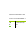
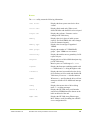
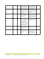
Document Conventions
The table lists the icons that indicate special kinds of information in this guide, with
an example of each icon.
Icon
Usage
Caution:
A Caution icon emphasizes information that helps
you avoid improperly configuring the system.
Note:
A Note icon draws your attention to significant
information.
A Web icon indicates tasks that can be performed
in the VMA Web Interface.
Web:
AM456-9007B Rev 02
HP VMA SAN Gateway Installation and User Guide
11
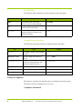
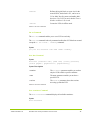
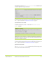
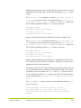
Text Formatting
The following table summarizes the font conventions used in this guide.
Font
Usage
Example
Bold
Object labels in the VMA Web
Interface, such as column headings.
Italic
Provides emphasis and identifies
variables and document titles.
Monospace
Commands, prompts, parameters,
parameter options, file names, and
command examples.
User Name
login:
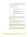
Command Syntax Conventions
The following conventions define the command syntax in this guide.
Font
Usage
Example
Monospace
Commands, prompts, and command
examples.
login:
Monospace bold
Input you must enter exactly as
shown.
login: admin
Monospace italic
Variables for which you must supply <IP address>
a value are printed in italics and
enclosed in angled brackets < >.
...
Repeat the previous element.
[]
Optional parameter.
|
Choose from one of the parameters.
[block | cache]
Security & Compliance
HP cannot be responsible for unauthorized use of equipment and will not make
allowance or credit for unauthorized use or access.
Compliance Information
12
AM456-9007B Rev 02
HP VMA SAN Gateway Installation and User Guide
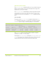
Notice
Description
FCC Class A
Compliance
"This device complies with Part 15 of the FCC Rules. Operation is subject to the
following two conditions: (1) This device may not cause harmful interference, and
(2) this device must accept any interference received, including interference that
may cause undesired operation."
This equipment has been tested and found to comply with the limits for a Class A
digital device, pursuant to Part 15 of the FCC Rules. These limits are designed to
provide reasonable protection against harmful interference when the equipment is
operated in a commercial environment. This equipment generates, uses, and can
radiate radio frequency energy and, if not installed and used in accordance with the
instruction manual, may cause harmful interference to radio communications.
Operation of this equipment in a residential area is likely to cause harmful
interference, in which case, you are required to correct the interference at your own
expense.
Canada
This class A digital apparatus complies with Canadian ICES-003.
Cet appareil numérique de la classe A est conforme à la norme NMB-003 du
Canada.
CISPR22
Warning: This is a class A product. In a domestic environment, this product may
cause radio interference, in which case, the user may be required to take adequate
remedial measures.
Japan
AM456-9007B Rev 02
HP VMA SAN Gateway Installation and User Guide
13
Getting Help
Contacting HP
Before you contact HP
Be sure to have the following information available before you contact HP:
•
Technical support registration number (if applicable).
•
Product serial number
•
Product model name and number
•
Product identification number
•
Applicable error message
•
Add-on boards or hardware
•
Third-party hardware or software
•
Operating system type and revision level.
HP contact information
For the name of the nearest HP authorized reseller:
•
In the United States, see the HP US service locator webpage (http://
welcome.hp.com/country/us/en/wwcontact.html).
•
In other locations, see the Contact HP worldwide (in English) webpage (http:/
/welcome.hp.com/country/us/en/contact_us.html).
For HP technical support:
•
In the United States, for contact options see the Contact HP United States
webpage (http://welcome.hp.com/country/us/en/contact_us.html).
To contact HP by phone, call 1-800-HP-INVENT (1-800-474-6836). This
service is available 24 hours a day, 7 days a week. For continuous quality
improvement, calls may be recorded or monitored.
If you have purchased a Care Pack (service upgrade), call 1-800-633-3600.
•
In other locations, see the Contact HP worldwide (in English) webpage (http:/
/welcome.hp.com/country/us/en/contact_us.html).
Subscription Service
HP recommends that you register your product at the subscriber’s Choice for
Business website (http://www.hp.com/country/us/en/contact_us.html).
14
AM456-9007B Rev 02
HP VMA SAN Gateway Installation and User Guide
After registering, you will receive email notification of product improvements,
new driver versions, firmware updates, and other product resources.
Reference Documents
•
HP VMA-series VMA Array Installation and Service Guide
Documentation feedback
HP welcomes your feedback. To make comments and suggestions about product
documentation, send a message to [email protected].
AM456-9007B Rev 02
HP VMA SAN Gateway Installation and User Guide
15
16
AM456-9007B Rev 02
HP VMA SAN Gateway Installation and User Guide
CHAPTER 1
HP VMA SAN Gateway Overview
Introduction to the HP VMA SAN Gateway
The HP VMA-series storage products are designed for I/O intensive server
applications such as high performance databases. Flash memory offers tremendous
performance advantages over traditional hard disk drive systems enabling data
centers to consolidate hard disk drives/spindles and reduce the number of servers/
CPUs and associated software licenses.
The HP VMA provisions flash memory through systems consisting of VMA
Arrays (HP VMA Arrays) and HP VMA SAN Gateways (HP VMA SAN
Gateway). These units are combined and managed together as nodes within a
cluster by means of the vCLUSTER management software.
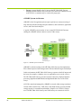
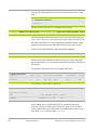
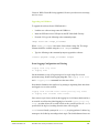
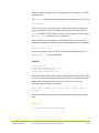
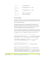
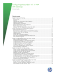
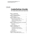
Figure 1.1 HP VMA SAN Gateway System
Within this clustered system, the HP VMA SAN Gateways act as intelligent nodes
providing connectivity to the data center’s network and allowing multiple hosts/
AM456-9007B Rev 02
HP VMA SAN Gateway Installation and User Guide
17
servers to share the high performance flash VMA Arrays. Sharing reduces costs
and allows hosts to cooperate.
The HP VMA Arrays provide high capacity flash storage with RAID protection
using a special flash-optimized algorithm (vRAID). This algorithm minimizes
latency and provides data integrity very efficiently.
HP VMA SAN Gateways support vSHARE, a LUN management solution for SAN
block storage.
•
HP VMA SAN Gateways with vSHARE provide for flexible LUN
provisioning, LUN reservations, and full-speed LUNs. Each LUN can use the
full IOPS/bandwidth of the HP VMA Array platform if the other LUNs are
idle.
vSHARE Architecture
A vSHARE system is built for performance and high Reliability, Availability and
Serviceability (RAS). The system fits with standard 19-inch racks in hot/cold isles
and can coexist with other data infrastructure without special facilities. A system
is built with the following primary components:
•
vSHARE: vSHARE software provides block storage functionality. It is
deployed on the HP VMA SAN Gateways. This software implements Fibre
Channel and manages LUNs and the initiator-target relationships.
Note: HP
18
only supports the Fiber Channel protocol.
•
HP VMA SAN Gateways: Each HP VMA SAN Gateway provides network
connectivity (typically 4 x 8Gb Fibre Channel (FC) or 4 x 10GbE), processing
and DRAM to support the vSHARE function. The typical vSHARE HP VMA
SAN Gateway supports eight processing cores and 12GB of DRAM for
maximum performance of over 400K IOPS at 4kB block size. Up to 32
gateways can be included in a single vSHARE system.
•
VMA Arrays: These VMA Arrays contain up to 40TB of raw flash memory
per array and 30TB of usable space. Unlike many other arrays, the flash
memory is RAID protected and hot-swappable to ensure maximum uptime
and very low data loss probabilities.
•
HP VMA Memory Modules: The memory modules reside within the VMA
Arrays and provide the flash memory and controllers required for high
performance flash storage. These modules are hot-swappable with minimal
impact on cache performance.
•
vCLUSTER Management Software: Clustering with automatic failover of
virtual IP (VIP) addresses, Fibre Channel paths and management software are
AM456-9007B Rev 02
HP VMA SAN Gateway Installation and User Guide
provided on the HP VMA SAN Gateways and VMA Arrays to enable the
systems to be configured and monitored as a single system. SNMP and callhome e-mail alerts are sent in the event of hardware failures or other critical
events.
The internal architecture of the vSHARE system is designed for minimum latency
and multipathing the HP VMA SAN Gateway and the VMA Arrays to improve
availability. This Intelligent Flash Storage architecture eliminates the software
required for cache control, RAID control and flash memory control and replaces
them with flash memory optimized architectures, which provide data protection
and high performance. Latency is reduced by implementing many of the data path
functions in hardware.
A vSHARE system typically consists of one or more HP VMA SAN Gateways
running the vSHARE software and one or more VMA Arrays.
In this environment, the HP VMA SAN Gateways are targets, and the hosts (for
example, a database server or application server) are the initiators. The storage
systems have storage target devices, LUNs, which the hosts access through the HP
VMA SAN Gateways. The LUNs are part of large storage arrays and they can be
allocated and provisioned as they are needed.
vSHARE Feature Summary
vSHARE runs as software on the HP VMA SAN Gateway managing SAN block
storage and providing high performance processing, high bandwidth DRAM, and
high bandwidth access to the VMA Arrays.
Each vSHARE HP VMA SAN Gateway operates as a SAN (Fibre Channel), and
provides access to LUNs that are stored on its attached VMA Arrays.
Note: HP
VMA-series SAN Gateway supports only SAN (Fibre Channel)
connectivity
The LUN management capability of the vSHARE software is very feature rich and
has many patent-pending capabilities. Four of the most important features are
flexible LUN mapping, full-speed LUNs, shared LUNs, and scale-out clustering:
•
AM456-9007B Rev 02
Flexible LUN Mapping: The vSHARE software formats each VMA Array
into a container of usable address space. Each container is then split into 1GB
flashlets. Up to 1024 LUNs can be created on each array with each assigned
HP VMA SAN Gateway Installation and User Guide
19
any number of flashlets. There is no need for flashlets to be contiguous and
hence LUNs can be packed very well with no wasted space.
•
Full-Speed LUNs: Each flashlet and hence each LUN is striped across all of
the VIMMs in a flash VMA Array. By doing this, the performance of the
LUN is only limited by the performance of the whole VMA Array.
•
Shared LUNs: Each LUN can be accessed using Fibre Channel and can be
shared by many servers in a cluster.
•
Scale-out Clustering: vSHARE leverages the rich clustering capabilities of
vCLUSTER to provide a single web, SNMP, e-mail and XML provisioning
and management API on a system that can scale to 2.5PB, 16,000 LUNs and
10M IOPS. Flash VMA Arrays can be added dynamically without
interruption of existing LUNs and users.
•
Active-Active High Availability (HA) configuration: vSHARE provides the
ability to have dual redundant HP VMA SAN Gateways servicing I/O
requests for attached VMA Arrays. For best performance, the configuration
requires that client initiators use multipath I/O (MPIO) software with a roundrobin scheduling algorithm.
LUNs are accessible in an active-active configuration via either HP VMA SAN
Gateway in an HA pair. Clients using MPIO can continue I/O through either
HP VMA SAN Gateway as long as at least one path is still available.
vCLUSTER Architecture
A typical HP VMA SAN Gateway cluster consists of one or more HP VMA SAN
Gateways (nodes), one of which is designated as the master node, another is
designated as the standby node, and additional nodes are designated as “normal”
nodes.
The HP VMA SAN Gateways provide connectivity to the network and allow
multiple servers to share the high performance flash VMA Arrays. Depending on
the configuration, HP VMA SAN Gateways may be used for block or file storage.
The VMA Arrays provide high capacity flash storage with RAID protection.
In an HP VMA SAN Gateway cluster the first HP VMA SAN Gateway added to
the cluster is designated as the Master HP VMA SAN Gateway (master node).
Configurations defined in the master node are inherited by every other node in the
cluster. Should the master node fail, the standby node takes over the master role,
and cluster management traffic is automatically redirected to the new master node.
20
AM456-9007B Rev 02
HP VMA SAN Gateway Installation and User Guide
vCLUSTER management software enables you to manage the HP VMA SAN
Gateways and VMA Arrays in the cluster as a single system using either the CLI
or the VMA Web Interface.
AM456-9007B Rev 02
HP VMA SAN Gateway Installation and User Guide
21
22
AM456-9007B Rev 02
HP VMA SAN Gateway Installation and User Guide
CHAPTER 2
Installing and Upgrading the HP VMA SAN
Gateway
Deployment Overview
VMA-series SAN Gateway deployment occurs in five distinct phases. Each phase
of the deployment process must be completed before you can proceed to the next
phase of the deployment.
•
Phase 1: HP VMA SAN Gateway Installation includes the unpacking,
racking, and cabling of HP VMA SAN Gateway hardware.
•
Phase 2: System Network Configuration includes the configuration of
network settings and HP VMA SAN Gateway system network connections.
•
Phase 3: Memory Array Configuration includes the installation and
configuration of Memory Array to support NFS caching (vCACHE) or block
storage (vSHARE).
•
Phase 4: Cluster Configuration includes the configuration of the HP VMA
SAN Gateway cluster.
•
Phase 5: vSHARE Configuration includes the configuration of the HP VMA
SAN Gateway cluster block storage (vSHARE).
Four of the five phases of an HP VMA SAN Gateway deployment are described in
detail in this manual. Phase 3: Memory Array Configuration is described in the HP
VMA-Series Memory Array Installation and Service Guide.
AM456-9007B Rev 02
HP VMA SAN Gateway Installation and User Guide
23
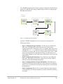
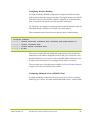
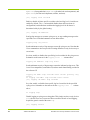
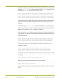
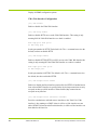
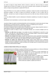
The diagram below shows the five phases of HP VMA SAN Gateway
configuration and the discrete steps required within each phase of an
implementation.
Figure 2.1 HP VMA SAN Gateway Deployment Flowchart
Phase 1: HP VMA SAN Gateway Installation
In this phase, you unpack and install the physical hardware and configure network
components:
Phase 1, HP VMA SAN Gateway Installation, includes the following procedures:
24
AM456-9007B Rev 02
HP VMA SAN Gateway Installation and User Guide
•
Unpacking HP VMA SAN Gateway Hardware Components: The first step
in the hardware installation phase is to unpack the HP VMA SAN Gateway
shipping box and confirm that all components are present.
•
Rack-mounting the HP VMA SAN Gateway Chassis: The second step is to
mount the HP VMA SAN Gateway chassis in the rack.
•
Connecting to Memory Arrays with PCIe Cables: The third step is to
connect each HP VMA SAN Gateway to one or more Memory Arrays using
PCIe cables.
•
Connecting Power: The fourth step is to connect to a power feed.
•
Connecting the Serial Console and Management LAN: The fifth step is to
connect the serial console and management LAN.
•
Cabling and Configuring Network Connections: In this step you connect
the HP VMA SAN Gateway to network switches using 10GbE or 8Gb Fibre
Channel cables and, optionally, to configure support on the cluster and
network switches for bonded interfaces and VLANs.
All Phase 1 configuration procedures are described in HP VMA SAN Gateway
Installation on page 27.
Phase 2: Network Configuration
Phase 2, System Network Configuration, includes the following procedure:
•
Configuring Network Settings: You set up and define the network settings
for the HP VMA SAN Gateway cluster. During this phase you must configure
the following IP addresses, parameters, and names: the public interface IP
address and netmask for each node (HP VMA SAN Gateway in the cluster).
The Phase 2 configuration procedure is described in Cluster VLAN Configuration
on page 39.
Phase 3: Memory Array Configuration
In this phase, you install and configure the Memory Arrays. These procedures are
discussed in detail in the HP VMA-series VMA Array Installation and Service Guide.
Phase 4: Cluster Configuration
In this phase, you connect to the HP VMA SAN Gateway and define the HP VMA
SAN Gateway cluster and global cluster parameters. An HP VMA SAN Gateway
cluster consists of one or more HP VMA SAN Gateway nodes. Using the
configuration wizard greatly simplifies this process.
AM456-9007B Rev 02
HP VMA SAN Gateway Installation and User Guide
25
Phase 4, HP VMA SAN Gateway Configuration, includes the following
procedures:
•
Configuring the Master HP VMA SAN Gateway: The first step is to
configure the master node of the HP VMA SAN Gateway cluster and define
the global cluster parameters, which are inherited by each node subsequently
added to cluster.
•
Configuring additional HP VMA SAN Gateways: Connect to each
remaining HP VMA SAN Gateway node to set its hostname and local system
parameters.
All Phase 4 configuration procedures are described in CHAPTER 3, Configuring
and Managing Clusters on page 37.
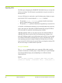
Phase 5: vSHARE Configuration
During this phase you configure the HP VMA SAN Gateway cluster to support
block storage with vSHARE.
vSHARE
vSHARE configuration includes the following steps:
•
Configuring Containers: The first step is to format the VMA Array to
manage block storage and create one or more containers to manage the LUNs.
•
Configuring the Target Ports: The second step is to configure the target
ports. Target ports may be used to control access to LUNs, which is useful for
security and bandwidth management.
If using Fibre Channel, the target ports are automatically configured when you
create the storage container on the Memory Array.
26
•
Configuring Initiator Groups and Initiators: The third step is to configure
the initiator groups and add one or more initiators to each initiator group.
Access to LUNs may be restricted by initiator group or on an initiator-byinitiator basis.
•
Configuring LUNs: LUNs are created within the storage containers on the
Memory Arrays. LUNs inherit attributes from the container in which they are
created.
•
Exporting LUNs: The LUNs must be exported to the initiator groups or
initiators via target ports. Only those initiator groups or initiators to which the
LUN is exported may access the LUN. Access may be further restricted to a
specific target port.
AM456-9007B Rev 02
HP VMA SAN Gateway Installation and User Guide
HP VMA SAN Gateways running vSHARE can be deployed in a High Availability
(HA) configuration, where two HP VMA SAN Gateways provide active-active
access to a Memory Array. Data is accessible via both HP VMA SAN Gateways.
If one of the Gateways fails, or a link along one of the paths to the Array goes down,
data is available seamlessly via the other Gateway.
All vSHARE configuration procedures are described in CHAPTER 4, Configuring
vSHARE on page 65.
HP VMA SAN Gateway Installation
The first phase of an HP VMA SAN Gateway deployment requires that you unpack
and install all hardware, connect power and PCIe cables, and connect and configure
network cabling.
Phase 1, Hardware Installation, includes the following procedures:
•
Unpacking HP VMA SAN Gateway Hardware Components: The first step
in the hardware installation phase is to unpack the HP VMA SAN Gateway
shipping box and confirm that all components are present.
•
Rack-mounting the HP VMA SAN Gateway Chassis: The second step is to
mount the HP VMA SAN Gateway chassis in the rack.
•
Connecting to Memory Arrays with PCIe Cables: The third step is to
connect each HP VMA SAN Gateway to one or more Memory Arrays using
PCIe cables.
•
Connecting Power: The fourth step is to connect to a power feed.
•
Connecting network interfaces: The fifth step is connect all network
interfaces.
Unpacking HP VMA SAN Gateway Hardware
The first step in the hardware installation process is to unpack the shipping box and
carefully inspect all materials. If you have any problems with your order, contact
HP Customer Service for further instructions.
AM456-9007B Rev 02
•
Depending on your installation location, you may find it easier to connect
interface cables to the HP VMA SAN Gateway before installing them into the
equipment rack.
•
Read through this entire chapter and plan your installation according to your
location before installing the equipment. The following procedures and the
order in which they appear are general installation guidelines only.
HP VMA SAN Gateway Installation and User Guide
27
Required Installation Tools
The following tools are required during the installation process:
•
Null Modem Cable or KVM (Keyboard/Video/Mouse) access to console.
•
Network requirements: The HP VMA SAN Gateway uses Gbit Ethernet for
management and cluster network connections.
Front View
The front panel has Power and Reset buttons that allow you to start, stop, or reset
the HP VMA SAN Gateway.
Caution: Using
the Power button to turn off the system power removes the main
power but keeps standby power. Before servicing, you must therefore unplug the
system.
The following LEDs are present on the HP VMA SAN Gateway:
28
•
NIC1-4
•
Power supplies 1 and 2
•
Overtemp
•
DIMM status
•
Processor status
•
Fan status
•
HDD
•
Power
AM456-9007B Rev 02
HP VMA SAN Gateway Installation and User Guide
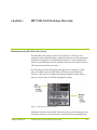
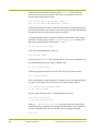
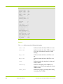
Rear View
The rear panel provides the interfaces for input and output devices, power supplies,
cluster management, network traffic, and one or more Memory Arrays.
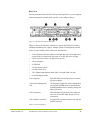
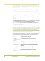
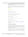
Figure 2.2 HP VMA SAN Gateway Back Pane
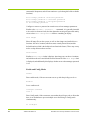
Figure 2.2 shows the interfaces available on a typical HP VMA SAN Gateway
including redundant power supplies, multiple options for management, and the
choice of either 10GbE or Fibre Channel for data transfers:
•
1: Fibre Channel Connectors (hba-a is top right, hba-b is bottom right, hba-c
is top left, hba-d is bottom left. Port ones are on left, Port twos on right)
•
2: PCIe Connectors (Slot 1 on right, Slot 4 on left)
•
3: Power Supplies
•
4: USB Ports
•
5: Video Port (not used)
•
6: Serial Console Port
•
7 & 9: Management Ethernet Ports (Eth1 is on right, Eth4 is on left)
•
8: iLO Management Port
Power Supplies
Each HP VMA SAN Gateway has two sockets
for power supplies.
iLO Remote Management
Port
The Integrated Lights-Out remote management
port supports the IPMI protocol and functions
enabling administrators to remotely manage the
Memory Gateway.
PCIe Connectors
Each HP VMA SAN Gateway may connect to
up to one or more HP VMA Arrays via PCIe
connections.
Fibre Channel Connectors
8-Gigabit Fibre Channel connectors provide the
network interfaces.
Table 2.1 Rear Panel Interfaces
AM456-9007B Rev 02
HP VMA SAN Gateway Installation and User Guide
29
Serial Console Port
The serial port may be used for CLI access.
Gbit Ethernet Ports
Two Gbit Ethernet ports provide management
access to the HP VMA SAN Gateway cluster.
Table 2.1 Rear Panel Interfaces
Rack-Mounting HP VMA SAN Gateways
The next step in the hardware installation of an HP VMA SAN Gateway is to rackmount the HP VMA SAN Gateway chassis.
The HP VMA SAN Gateway may be racked as you would a normal server. The
chassis should be placed within one meter of the attached Memory Arrays so that
PCIe cables can be easily connected.
Connecting to Memory Arrays with PCIe
The next step in the hardware installation of a HP VMA SAN Gateway is to
connect each HP VMA SAN Gateway to one or more Memory Arrays using PCIe
cables.
30
AM456-9007B Rev 02
HP VMA SAN Gateway Installation and User Guide
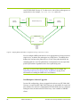
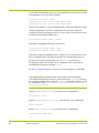
In typical configurations, either a single stand-alone or two redundant paired VMA
SAN gateways are connected to one or two VMA Arrays using PCIe cables.
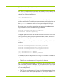
Figure 2.3 HP VMA SAN Gateway and Memory Array Back Panels
If one HP VMA SAN Gateway were to fail, the other HP VMA SAN Gateway
would immediately become the primary owner of that Memory Array.
Connecting Power
The next step in the hardware installation of a HP VMA SAN Gateway is to
connect to a power source.
AM456-9007B Rev 02
HP VMA SAN Gateway Installation and User Guide
31
The HP VMA SAN Gateway chassis has two single-phase power supplies installed
prior to shipping. The IEC-C14 male receptacles accept two IEC-C13 female
connectors.
Figure 2.4 HP VMA SAN Gateway Power Supplies
Each HP VMA SAN Gateway features redundant power supplies. Connect the AC
power cord to either power receptacle on the HP VMA SAN Gateway or both.
For maximum availability, the power supplies for each HP VMA SAN Gateway
and HP VMA Array should be connected to different power feeds to provide
failover in case of a failed power supply or loss of a power feed.
In a typical system containing two HP VMA SAN Gateways and two Memory
Arrays, eight 208V outlets are recommended.
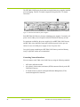
Connecting Network Interfaces
You can connect to the VMA-series SAN Gateway using the following methods:
32
•
APC and a null modem cable.
•
A keyboard, video monitor, and mouse (KVM) connected directly to the HP
VMA SAN Gateway.
•
A Virtual serial text console or Integrated Remote Management (VGA)
console through the iLO interface.
AM456-9007B Rev 02
HP VMA SAN Gateway Installation and User Guide
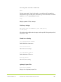
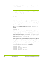
A typical HP VMA SAN Gateway system will have three management interfaces.
Figure 2.5 Network Interfaces
•
1-2 & 4-5: Management Ethernet Ports (Eth1 is on right, Eth4 is on left)
•
3: iLO Management Port
In this example, 8GB Fibre SAN ports are the primary ports for failover
management. These interfaces may used as individual ports configured for
different networks or they may be bonded together to run on the same subnet for
increased throughput and reliability.
The default public interface—the Ethernet port used for cluster management—is
eth1. Cluster management and cluster data traffic must share the same physical
cabling. For cable redundancy, the eth1 and eth2 interfaces can be bonded together
as eth0, in which case eth0 is used for the cluster master interface and the cluster
interface. In a single Ethernet cable configuration, the eth1 port is used for both
cluster management and cluster data traffic. To hide cluster data traffic from the
management network, a VLAN can be used for the cluster interface. For more
information, see Network Interface Commands on page 148.
Note: For proper operation in a vSHARE High Availability (HA) configuration, the
management and cluster interfaces should be bonded to a single interface, eth0, and
that interface becomes the management and cluster interface.
Null Modem Cable Connection
Connect to the public interface by connecting a null modem cable to the
communication port of a PC.
AM456-9007B Rev 02
HP VMA SAN Gateway Installation and User Guide
33
The settings for the modem are as follows:
Port Setting Name
Value
Bits per second
9600
Data bits
8
Parity
None
Stopbits
1
Flowcontrol
None
Table 2.2 Modem Settings
KVM Connection
If a null modem cable is not available, a KVM (USB keyboard, VGA video
monitor, and USB mouse) may be used to directly plug into the public interface for
configuration.
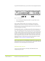
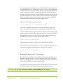
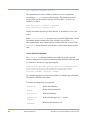
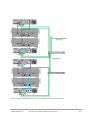
Connecting Data Ports to Network Switches
In a typical configuration, two HP VMA SAN Gateways are connected to two
switches. Each HP VMA SAN Gateway has dual HBAs and connects to two
switches.
Figure 2.6 HP VMA SAN Gateway Network Connectivity
Each HP VMA SAN Gateway connects to the network via four 8Gb Fibre Channel
connectors. Each port is functionally identical and is provided for improved
34
AM456-9007B Rev 02
HP VMA SAN Gateway Installation and User Guide
throughput and availability. All the Ethernet or Fibre Channel ports on the HP
VMA SAN Gateway may be connected to the same switch.
Additional FC ports can be added to an HP VMA SAN Gateway by using HP
supplied HBAs (part number AJ764A), each of which supports two data ports. The
maximum number of HBAs supported is four.
AM456-9007B Rev 02
HP VMA SAN Gateway Installation and User Guide
35
36
AM456-9007B Rev 02
HP VMA SAN Gateway Installation and User Guide
CHAPTER 3
Configuring and Managing Clusters
vCLUSTER Overview
Cluster management software provides for the central management of multiple HP
VMA SAN Gateways and VMA Arrays as nodes within a single system. Using
vCLUSTER, multiple HP VMA SAN Gateways and VMA Arrays may be
managed from the CLI or VMA Web Interface.
An HP VMA SAN Gateway cluster consists of one or more HP VMA SAN
Gateways (nodes), one of which is designated as the master node, and a second (in
a cluster of more than one node) is designated as the standby node. Any other nodes
in the cluster are designated as normal nodes. Should the master node fail, the
standby node replaces it and becomes the master node, and cluster management
traffic is automatically redirected to the new master node.
Cluster management activities include monitoring the HP VMA SAN Gateways
(nodes) in the HP VMA SAN Gateway cluster, stopping or rebooting nodes, and
upgrading the vSHARE running on the cluster. Every node in the cluster may be
managed using controls in the CLI or VMA Web Interface.
Cluster Network Configuration
Phase 2, System Network Configuration, includes the following procedures:
•
AM456-9007B Rev 02
Configuring Network Switches: The first step of Phase 2, System Network
Configuration, is to set up and define the network switches for the HP VMA
SAN Gateway cluster. During this phase you must configure the following IP
addresses, parameters, and names: the public interface IP address and netmask
HP VMA SAN Gateway Installation and User Guide
37
for each node (HP VMA SAN Gateway in the cluster), the cluster
management VIP address, and the VMA Array IP address.
•
Configuring Network Connections: The second step of Phase 2 is to
configure support on the cluster and network switches for bonded interfaces
and VLANs.
Configuring Network Settings
The first step of Phase 2, System Network Configuration, is to set up and define the
network settings for the HP VMA SAN Gateway cluster.
During this phase you must configure the following IP addresses, parameters, and
names: the public interface IP address and netmask for each node (HP VMA SAN
Gateway in the cluster), the cluster management VIP address, and the VMA Array
IP address.
Defining Initial IP Addressing
The following IP address assignments must be performed via console or null
modem cable to the network switches of the HP VMA SAN Gateway cluster:
•
Public Interface Name and IP Address: For each node, define the public
interface name, IP address, and an associated netmask for the system’s private
address requirements. (DHCP can be used for these addresses; however, most
installations use hard-coded IP addresses.)
•
Cluster Management VIP: Define the cluster management virtual IP
address. The cluster management VIP directs all cluster management traffic to
the public interface on the master node.
•
VMA Array IP Address: Define the VMA Array management IP address.
Defining Additional Parameters
The following parameters may be set via the serial console port on the Master
Gateway or via the cluster management VIP address:
38
•
Global network parameters: Default Gateway or DNS Server information.
•
NTP Server IP address for time synchronization.
•
SMTP Server IP address for email configuration.
•
Multiple IP addresses for the accelerated VIPs that enable clients to access the
system.
•
Private VLAN for cluster communication.
AM456-9007B Rev 02
HP VMA SAN Gateway Installation and User Guide
Defining Cluster Name and Host Names
Names for the cluster and each HP VMA SAN Gateway may be set via the serial
console port on the Master Gateway or via the cluster management VIP address:
•
Cluster name to identify the VMA-series SAN Gateway.
•
Host names for each HP VMA SAN Gateway in the cluster. Typically, these
would be given obvious names such as “vmg-n1” and “vmg-n2” or something
similar.
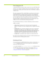
Configuring Network Connections
The second step of Phase 2 is to configure support on the cluster and network
switches for bonded interfaces and VLANs.
Interface Bonding
Interface bonding is the bundling of several physical ports together to form a single
logical channel. One bonding method is the Link Aggregation Control Protocol
(LACP), which can optionally be used to allow, network devices to negotiate the
automatic bundling of links with other devices that implement LACP.
To utilize interface bonding, you must (1) bond together one or more network
interfaces together using the network bond command and (2) if using LACP,
ensure that the network switches are LACP-enabled. For more information, see
Network Bond Commands on page 150.
Depending on the switch’s capabilities and configuration, the port LACP settings
may be either active or passive. Active mode is recommended because no nonaggregated traffic is expected from the HP VMA SAN Gateway.
If interface bonding is used, eth0 is defined as a bonded interface consisting of two
or more network interfaces. All bonded interfaces share the same subnet. The LOM
port cannot be configured using vCLUSTER. For more information on interface
bonding see Network Interface Commands on page 148.
Cluster VLAN Configuration
The VMA-series SAN Gateway uses a separate cluster network for low-latency,
low-bandwidth communication between HP VMA SAN Gateways in a cluster.
AM456-9007B Rev 02
HP VMA SAN Gateway Installation and User Guide
39
To separate cluster network traffic from cluster management traffic, you can
configure virtual LAN (VLAN). Network switches must also be configured to
provide a private VLAN if it will be used for the cluster network traffic.
For best performance and minimal impact on the customer network, HP
recommends configuring a private network for use by the cluster through VLAN
tagging.
Each network switch port connected to a HP VMA SAN Gateway should be
configured to allow VLAN-tagged traffic for the given cluster VLAN ID. By
default, the cluster VLAN is assigned to VLAN ID 10. This is a configurable
option that you can change to suit your network setup. For more information, see
VLAN Commands on page 151.
Some switch vendors, including Cisco, do not allow untagged traffic over an LACP
link. If you are using this type of switch, you must provide the HP VMA SAN
Gateway with the public-facing VLAN (in addition to the cluster VLAN) and tag
the ports appropriately.
Note: The system uses mDNS for cluster communication. This needs to be allowed
on all switches and uses group 224.0.0.251.
HP VMA SAN Gateway Cluster Configuration
After the system hardware is set up and cabled correctly and the VMA Array is
configured, you may configure the HP VMA SAN Gateway cluster.
Phase 4, HP VMA SAN Gateway Cluster Configuration, includes the following
procedures:
•
Configuring the Master HP VMA SAN Gateway: The first step is to
configure the master node of the HP VMA SAN Gateway cluster and define
the global cluster parameters, which are inherited by each node subsequently
added to cluster.
•
Configuring additional HP VMA SAN Gateways: Connect to each
remaining HP VMA SAN Gateway node to set its hostname and local system
parameters.
Once the initial configuration is set up, you can use the VMA Web Interface to
finish configuring the application, as described in VMA Web Interface Reference
on page 177.
40
AM456-9007B Rev 02
HP VMA SAN Gateway Installation and User Guide
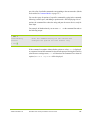
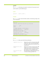
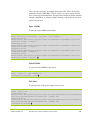
Logging into the HP VMA SAN Gateway
Once you have connected to the KVM console or serial port, you are prompted to
log in. Enter the username admin (bold shows user input):
tc500-1973fa login: admin
The admin user does not have a default password.
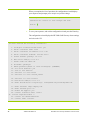
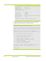
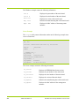
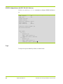
Once logged in, you are prompted whether to use the configuration wizard, as
shown below:
Unauthorized Access Prohibited. Usage of the HP VMA SAN Gateway is subject
to the HP License agreement which is included under this product's
Web Interface Help section.
HP VMA SAN Gateway
HP VMA SAN Gateway configuration wizard
Press '?' for help, Ctrl+B to go back to the previous step.
Default value is in square brackets: press Enter to accept it.
Press Ctrl+R to clear default to enter empty string.
Press Ctrl+C to jump to the end of the wizard at any time.
Do you want to use the wizard for initial configuration?
The configuration wizard will prompt you to enter the configuration information
and parameters discussed in the following subsections.
Configuring the Master HP VMA SAN Gateway
The first step in Phase 2 of an HP VMA SAN Gateway deployment is to configure
the master node of the HP VMA SAN Gateway cluster and define the global cluster
parameters, which are inherited by each node subsequently added to cluster.
A typical HP VMA SAN Gateway vCLUSTER consists of one or more HP VMA
SAN Gateways (nodes), one of which is designated as the master node and another
which is designated as the standby node. Additional nodes beyond the master and
standby in a vCLUSTER are called normal nodes.
AM456-9007B Rev 02
HP VMA SAN Gateway Installation and User Guide
41
The first HP VMA SAN Gateway added to the HP VMA SAN Gateway cluster is
the master node. The master node is the default gateway for all cluster management
tasks. The cluster management VIP directs all cluster management traffic to the
public interface—generally eth1 (or eth0 if a bonded interface is used)—on the
master node. Should the master node fail, the standby node replaces it and becomes
the master node, and cluster management traffic is automatically redirected to the
new master node.
Note: The vCLUSTER roles of master, standby, and normal are with respect to
cluster nodes for configuration management. The pairing of HP VMA SAN
Gateway nodes for VMA Arrays in a High Availability (HA) configuration is not
based on these cluster roles, but by physical cabling.
For example, it is possible in a vCLUSTER to have an HA pair of Gateways for a
set of Arrays where neither node is a vCLUSTER master or standby. vSHARE
LUNs are defined and saved within the Arrays themselves. vSHARE LUN export
records are, however, managed and stored within the vCLUSTER configuration
database owned by the master node.
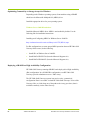
Master Node Parameters
All global cluster parameters are defined on the master node and are automatically
inherited by each additional node added to the cluster.
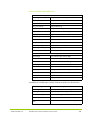
Please have all of the following information available for configuring the first HP
VMA SAN Gateway, the master node, in the cluster:
Public interface name
This specifies the Ethernet port that is used for
cluster management. If only a single Ethernet
cable will be used to connect the Gateway node,
then eth1 should be used. If both eth1 and eth2
will be cabled to the network, then they should be
bonded as eth0, and eth0 should be used as the
public interface.
Public interface IP address
& netmask
The interface IP address and netmask. (Note:
DHCP is not recommended.)
Default gateway
Recommended for access to the cluster from
outside of its local network.
Global default gateway
Enable or disable. HP recommends that you
enable the global default gateway.
Table 3.1 HP VMA SAN Gateway Settings
42
AM456-9007B Rev 02
HP VMA SAN Gateway Installation and User Guide
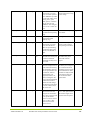
DNS server name(s)
Specify a primary and, optionally, a secondary
DNS server.
Domain name
The name of your local domain.
Hostname
A local hostname for the HP VMA SAN
Gateway.
This should be a unique host name for each
gateway.
Admin password
Setting a password is highly recommended.
Timezone
Set the clock timezone by specifying the zone and
subzones. (Use "?" to display zone names
interactively.)
NTP server
Optional and recommended.
Email notification
recipients, mail hub, & port
Set recipients to [email protected] for
HP Customer Support and at least one email alias
for your company, in a comma-separated list.
Enable HP support
Set autosupport to yes to ensure proper handling
of support issues.
Cluster interface name
The interface for internal vCLUSTER traffic. In a
single Ethernet-cabled Gateway, this is eth1. A
VLAN can be used instead to separate
vCLUSTER multicast traffic from management
traffic. If using a VLAN, the cluster interface
name is based on the VLAN ID. For example, if
you use VLAN #14 then the cluster interface
name is “vlan14”. In a redundant gateway pair
configuration (in which both eth1 and eth2 are
used) without a VLAN being used, then the eth0
bonded interface should be specified for the
cluster interface name.
Cluster expected nodes
Set the number of nodes (HP VMA SAN
Gateways) in the cluster. The minimum is 1 for a
standalone gateway.
Note that this is the expected number of HP VMA
SAN Gateway nodes only. Do not include the
number of VMA Arrays.
Cluster id
The cluster id is preconfigured with the HP VMA
SAN Gateway.
For standby and other members of a vCLUSTER
management group, use the master node cluster
ID
Table 3.1 HP VMA SAN Gateway Settings
AM456-9007B Rev 02
HP VMA SAN Gateway Installation and User Guide
43
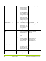
Cluster name
The name of the cluster used by DNS.
Cluster management IP
address & netmask
The virtual IP address (VIP) and netmask for
management of the cluster. The address and
netmask are assigned to the master node of the
cluster, and redirected as needed whenever
another node becomes the master.
Table 3.1 HP VMA SAN Gateway Settings
The fastest and easiest way to configure the master node of a HP VMA SAN
Gateway cluster is to use the configuration wizard.
Note that interface bonding and cluster VLAN configuration are not covered in the
configuration wizard. If you plan to use these features, you must configure them
using the CLI.
To simplify initial setup, or for single-Ethernet cable to Gateway configurations,
you can specify the eth1 interface as the answer for the “Public interface name” and
“Cluster interface name” questions in the wizard, and subsequently do the interface
bonding and VLAN configuration using the CLI.
See Network Bond Commands on page 150 for information on how to set up
bonding. See VLAN Commands on page 151 for information on how to configure
a VLAN.
Using the Configuration Wizard
The configuration wizard may be used locally on each gateway to configure every
HP VMA SAN Gateway in the cluster. Immediately after logging into each HP
VMA SAN Gateway, you will be prompted to choose between proceeding with the
configuration or escaping to the CLI.
•
If you respond “Yes” to the wizard prompt, the Configuration Wizard will
guide you through the steps required to configure the HP VMA SAN
Gateway.
•
If you respond “No” to the wizard prompt, the system enters the command
line interface (CLI) in Standard mode. (See Command Modes on page 117 for
more information about Standard mode.)
Note: HP recommends
that you use the Configuration Wizard.
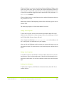
The configuration wizard interactively configures the cluster settings, prompting
you at each step to enter a value or accept the default (or the current setting, if
44
AM456-9007B Rev 02
HP VMA SAN Gateway Installation and User Guide
previously configured). After the last step, the wizard repeats your settings and lets
you return to any step if you want to make more changes.
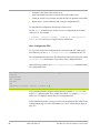
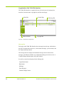
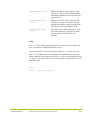
To rerun the Configuration Wizard, use the command configuration jumpstart from the CLI(confg) prompt.
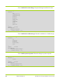
To configure the Master HP VMA SAN Gateway using the configuration
wizard:
1.
Connect and log in as admin.
The configuration wizard prompts you to use it for the initial configuration of
the HP VMA SAN Gateway.
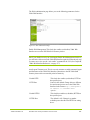
Do you want to use the wizard for initial configuration?
Yes
2.
Respond "Yes" to the wizard prompt.
You are prompted to answer a series of configuration questions. The responses
given for each question will configure the initial HP VMA SAN Gateway,
which becomes the master node.
Step 1: Configure as master/stand-alone? [yes]
3.
Reply “Yes” to Step 1: Configure as master/stand-alone?
By replying Yes, you define the current HP VMA SAN Gateway as the master
node of the cluster. You should answer Yes only for the master node or
standalone gateways. Answer No for all other nodes. There is a shorter list of
questions for the other nodes compared to the master node. A standby node will
be elected from the remaining nodes that form the vCLUSTER.
4.
AM456-9007B Rev 02
In each subsequent step, type a new value or press the Enter key to accept the
default value shown in square brackets (if one is present).
HP VMA SAN Gateway Installation and User Guide
45
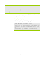
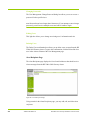
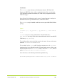
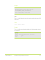
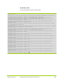
When you complete the list of questions, the configuration wizard displays
your responses and prompts you to accept or reject the settings:
To change an answer, enter the step number to return to.
Otherwise hit <enter> to save changes and exit.
Choice: █
5.
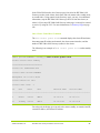
To save your responses, and exit the configuration wizard press the Enter key.
The configuration wizard displays the HP VMA SAN Gateway cluster settings
and exits to the CLI.
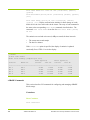
You have entered the following information:
1.
2.
3.
4.
5.
Configure as master/stand-alone: yes
Public interface name: eth0
Public interface IP address: 10.3.7.84
Public interface netmask: 255.255.252.0
Global default gateway: 10.3.4.1
6. DNS server name(s): 10.3.4.2
7. Domain name: mv.vmem.com
8. Hostname: gateway01
9. Admin password (Enter to leave unchanged): (CHANGED)
10. Set clock timezone: yes
11. Zone to use: America
12. Sub-zone 1 to use: North
13. Sub-zone 2 to use: United_States
14. Sub-zone 3 to use: Pacific
15. NTP server name(s): 10.1.1.2
16. Email Notification recipient(s): [email protected],[email protected]
17. Email mailhub: smtp.company.com
18. Email mailhub port: 25
19. Enable HP support: yes
20. Cluster interface name: vlan14
21. Cluster expected nodes: 2
22. Cluster id: 00500-0008-0105
23. Cluster name: cluster1
46
AM456-9007B Rev 02
HP VMA SAN Gateway Installation and User Guide
24. Cluster management IP address: 10.3.19.61
25. Cluster management IP netmask: 255.255.252.0
To change an answer, enter the step number to return to.
Otherwise hit <enter> to save changes and exit.
Choice: █
6.
To return to the configuration wizard after exiting, enter the command
configuration jump-start in the CLI. This command can be used
anytime to change the configuration settings.
Getting Help During Configuration
Additional usage advice is provided at the beginning of the wizard.
HP VMA SAN Gateway configuration wizard
Press '?' for help, Ctrl+B to go back to the previous step.
Default value is in square brackets: press Enter to accept
it.
Press Ctrl+R to clear default to enter empty string.
Press Ctrl+C to jump to the end of the wizard at any time.
AM456-9007B Rev 02
HP VMA SAN Gateway Installation and User Guide
47
Type "?" for help with the current step. For example, when setting the timezone you
can type "?" to display the possible values, along with general help:
...
Step 10: Set clock timezone? [yes]
Step 11: Zone to use? [UTC] America
Step 12: Sub-zone 1 to use? [Caribbean] ?
Caribbean Central North South
Press '?' for help, Ctrl+B to go back to the previous step.
Default value is in square brackets: press Enter to accept it.
Press Ctrl+R to clear default to enter empty string.
Step 12: Sub-zone 1 to use? [Caribbean] North
Step 13: Sub-zone 2 to use? [Canada] United_States
Step 14: Sub-zone 3 to use? [Alaska] ?
Alaska Arizona Central Eastern Hawaii Mountain Other Pacific
Press '?' for help, Ctrl+B to go back to the previous step.
Default value is in square brackets: press Enter to accept it.
Press Ctrl+R to clear default to enter empty string.
Step 14: Sub-zone 3 to use? [Alaska] Pacific
Step 15. NTP server name(s)? [0.0.0.0] 10.1.1.2
...
When the configuration is correct, press <Enter> at the Choice prompt to save the
configuration. The configuration wizard displays the HP VMA SAN Gateway
48
AM456-9007B Rev 02
HP VMA SAN Gateway Installation and User Guide
cluster settings and enters the CLI. If you changed the master node’s hostname or
the cluster’s name, the command prompt will show their new names. For example:
Choice: <Enter>
Configuration changes saved.
Cluster ID:
Cluster name:
Management IP:
Cluster master IF:
Cluster node count:
Local name:
Local role:
00500-0008-0105
cluster1
10.3.19.61/22
eth0
2
gateway01
master
Local state:
Master address:
Master state:
online
10.3.7.84 (ext) 169.254.72.138 (int)
online
*gateway01 [cluster1: master] (config) # █
Note: VLAN and interface bonding configuration are not part of the configuration
wizard and must be configured using the CLI. If you specified either a VLAN ID
or the bonded interface (eth0) for the “Public interface name” or “Cluster interface
name” questions, then additional steps are required. See Network Bond Commands
on page 150 for information on how to set up bonding. See VLAN Commands on
page 151for information on how to configure a VLAN. Need to better explain this.
Configuring Additional Gateways
The second step in Phase 2 of a deployment is to add and configure additional
member HP VMA SAN Gateways to the vCLUSTER.
A typical HP VMA SAN Gateway vCLUSTER consists of one or more HP VMA
SAN Gateways (nodes), one of which is designated as the master node and one
more which is designated as the standby node.
•
AM456-9007B Rev 02
Master node: The first node added to the cluster is the master node.
Configuration of the master node is described in Configuring the Master HP
VMA SAN Gateway on page 41.
HP VMA SAN Gateway Installation and User Guide
49
•
Standby node: The second node added to the cluster is automatically
designated as the standby node. Should the master node fail, the standby node
replaces it and becomes the master node, and cluster management traffic is
automatically redirected to the new master node.
•
Normal nodes: Each additional HP VMA SAN Gateway added to the cluster
is defined as a normal node. During the course of vCLUSTER operation, a
normal node can assume the role of standby or master. There is always only a
single master and at most a single standby node.
All global cluster parameters are defined on the master node and are automatically
inherited by each node added to the cluster. Consequently, the configuration of the
standby node and each subsequent normal node requires only seven steps as
compared to the 25 steps required to configure the master node.
Note that if a global cluster parameter is changed on a node other than the master
node, the changes will only take effect locally until the next time the master node
synchronizes with the rest of the cluster.
To configure a HP VMA SAN Gateway for addition into the vCLUSTER:
1.
Connect and log in as admin.
The admin user has no password initially; when the HP VMA SAN Gateway
joins the cluster, the admin role obtains the password that was set on the Master
HP VMA SAN Gateway.
The configuration wizard prompts you to use it for the initial configuration of
the HP VMA SAN Gateway.
Do you want to use the wizard for initial configuration?
Yes
2.
Reply "No" to Step 1: Configure as master/stand-alone?:
Step 1: Configure as master/stand-alone? [yes] no
3.
50
Provide values or accept defaults for steps 2 through 7.
AM456-9007B Rev 02
HP VMA SAN Gateway Installation and User Guide
A typical configuration of a normal node HP VMA SAN Gateway using the
configuration wizard might look like the following example:
Step
Step
Step
Step
Step
Step
Step
1:
2:
3:
4:
5:
6:
7:
Configure as master/stand-alone? [yes] no
Public interface name? [eth0]
Public interface IP address? [10.1.9.101]
Public interface netmask? [255.255.252.0]
Hostname? [gateway01] gateway02
Cluster interface name? [vlan14]
Cluster id? [00500-0008-0105]
The configuration wizard automatically completes settings that are defined by
the master node. In all but one of these steps, the settings are inherited from the
master node.
Step 2: Public interface name; Use the public interface name defined for the
master node.
Step 3: Public interface IP address for this HP VMA SAN Gateway.
Step 4: Netmask for the public interface IP address.
Step 5: Unique hostname for this specific HP VMA SAN Gateway.
Step 6: Cluster interface name; Use the interface name configured on the
master. Initially each gateway is pre-configured with its own unique cluster id
for standalone gateway operation.
Step 7: Cluster id; Use the same cluster id as configured on the master.
4.
When the configuration is correct, press <Enter> at the prompt to save the
configuration.
The configuration wizard displays the basic cluster settings and exits to the
CLI.
Choice: <Enter>
Configuration changes saved.
*** Warning: This system is a member of a cluster.
Shared configuration
must be changed on the cluster master.
AM456-9007B Rev 02
HP VMA SAN Gateway Installation and User Guide
51
Cluster ID:
Cluster name:
Management IP:
Cluster master IF:
Cluster node count:
Local name:
Local role:
Local state:
Master address:
Master state:
00500-0008-0105
cluster1
10.1.9.100/22
eth0
2
gateway02
standby
online
10.1.9.102 (ext) 169.254.9.21 (int)
online
*gateway02 [cluster1: standby] (config) # █
A typical configuration of a normal node HP VMA SAN Gateway using the
configuration wizard might look like the following example:
HP VMA SAN Gateway configuration wizard
Press '?' for help, Ctrl+B to go back to the previous step.
Default value is in square brackets: press Enter to accept
it.
Press Ctrl+R to clear default to enter empty string.
Press Ctrl+C to jump to the end of the wizard at any time.
You have entered the following information:
1.
2.
3.
4.
5.
6.
7.
Configure as master/stand-alone: no
Public interface name: eth0
Public interface IP address: 10.1.9.101
Public interface netmask: 255.255.252.0
Hostname: gateway02
Cluster interface name: vlan14
Cluster id: 00500-0008-0105
To change an answer, enter the step number to return to.
Otherwise hit <enter> to save changes and exit.
Choice: █
52
AM456-9007B Rev 02
HP VMA SAN Gateway Installation and User Guide
Note: VLAN
and interface bonding configuration are not part of the configuration
wizard and must be configured using the CLI. If you specified either a VLAN ID
or the bonded interface (eth0) for the “Public interface name” or “Cluster interface
name” questions, then additional steps are required. See Network Bond Commands
on page 150 for information on how to set up bonding. See VLAN Commands on
page 151for information on how to configure a VLAN.
Command Line and Web Interfaces
After the initial configuration parameters are set, you can access the VMA-series
SAN Gateway through its Web Interface (the VMA Web Interface) or its command
line interface (CLI) for further configuration and management.
The VMA Web Interface provides a subset of the commands available in the CLI;
HP recommends the VMA Web Interface for ease of use.
To access the VMA Web Interface, use a supported browser (with JavaScript and
cookies enabled) to open the following URL:
http://<IP address or hostname of Master Gateway>
and proceed to log in. Supported browsers include recent versions of Internet
Explorer, Firefox, Safari, and Chrome (see Supported Web Browsers on page 181
for details).
For detailed information about these two interfaces, see:
•
APPENDIX A:Command Line Interface on page 113
•
APPENDIX B:VMA Web Interface Reference on page 177
HP VMA SAN Gateway Cluster Management
Cluster management activities include monitoring the HP VMA SAN Gateways
(nodes) in the HP VMA SAN Gateway cluster, stopping or rebooting nodes, and
upgrading the software running on the cluster.
Management tasks can be performed either in the VMA Web Interface or in the
CLI. This chapter explains the tasks with CLI examples and gives references to
APPENDIX B:VMA Web Interface Reference on page 177, where the same tasks
are described using VMA Web Interface tools.
AM456-9007B Rev 02
HP VMA SAN Gateway Installation and User Guide
53
Cluster Management VIP
A typical HP VMA SAN Gateway cluster consists of one or more HP VMA SAN
Gateways, one of which is designated as the master node and one more which is
designated as the standby node. All other nodes in the vCLUSTER are considered
“normal” nodes.
The cluster management VIP, a virtual IP address, provides access to the cluster,
enabling administrators to manage and monitor all nodes of the management
cluster. This VIP is defined during initial configuration of the HP VMA SAN
Gateway management cluster and is assigned to the master node; if the master node
fails, the standby node replaces it and becomes the master node, and cluster
management traffic is automatically redirected to the new master node. A new
standby node will be elected from the remaining normal nodes.
Every HP VMA SAN Gateway in a cluster is defined by its node role (master,
standby, or normal):
•
Master Node: The master node is the primary node for managing the
Gateway vCLUSTER. The cluster management VIP is assigned to the master
node.
•
Standby Node: The second node configured in the cluster is automatically
designated as the standby node. The standby node is an active node that
performs services like the other nodes in the cluster. If the master node fails,
the standby node replaces it and becomes the master node, and cluster
management traffic is automatically redirected to the new master node.
•
Normal Node: Any additional cluster members are called normal nodes.
By using the cluster management VIP, you can ensure a reliable connection to the
current master node for all management activities.
Monitoring the Cluster
To monitor the nodes in an HP VMA SAN Gateway cluster, you can use the show
cluster commands in the CLI or the Gateways page in the Administration
section of the VMA Web Interface.
A very useful command is show cluster global brief, which may be used
on any HP VMA SAN Gateway in the cluster. For descriptions of the show
cluster commands and other cluster management commands, see Cluster
Configuration and Show Commands on page 146.
54
AM456-9007B Rev 02
HP VMA SAN Gateway Installation and User Guide
In the VMA Web Interface, the Gateways page lists all of the HP VMA SAN
Gateways (nodes) in the cluster, their status, and role (master node, standby node,
or normal node). Using controls in the Gateways page, you may view additional
information, stop the HP VMA SAN Gateway (remove it from the cluster), or
reboot it. If you stop a HP VMA SAN Gateway in this page, it can only be restored
to service by using the CLI. For more information, see Gateways Page on page
188.
Show Cluster Global Brief Command
The show cluster global brief command displays the cluster ID and name,
the management IP address and netmask, the cluster master interface, and the
number of HP VMA SAN Gateways (nodes) in the cluster.
The following is an example of show cluster global brief on the standby
node:
SM076 [NJ-Lab-vSHARE00: standby] # show cluster global brief
Global cluster state summary
==============================
Cluster ID: 99999-9999-1023
Cluster name: NJ-Lab-vSHARE00
Management IP: 10.10.0.38/24
Cluster master IF: eth1
Cluster node count:
ID
Role
2
State
Host
External Addr
Internal Addr
------------------------------------------------------------------------------2
master
online
SM075
10.10.0.37
10.10.0.37
3*
standby
online
SM076
10.10.0.143
10.10.0.143
For each node, the display gives its node role (master, standby, or normal), host ID,
external IP address, and internal IP address.
AM456-9007B Rev 02
HP VMA SAN Gateway Installation and User Guide
55
An asterisk after a node’s ID number designates the local node where you issued
the command.
Show Cluster Global Command
Without the brief option, the show cluster global command displays
additional information about each HP VMA SAN Gateway in the cluster. Instead
of using an asterisk to designate the local node ID, the label <--- (local node)
is used to identify the local node.
gateway02 [cluster1: standby] # show cluster global
Cluster ID:
00500-0008-0175
Cluster name:
cluster1
Management IP:
10.3.19.65/22
Cluster master IF:
eth1
Cluster node count:
2
Node Status:
Node ID: 1
<--- (local node)
Host ID: 75527d83e101
Hostname: vmg-vc1-n2
Node Role: master
Node State: online
Node internal address: 169.254.70.242, port: 60102
Node external address: 10.3.19.102
Recv. Heartbeats from: 2
Send Heartbeats to: 2
Node Status:
Node ID: 2
Host ID: e12080d777e6
56
AM456-9007B Rev 02
HP VMA SAN Gateway Installation and User Guide
Hostname: vmg-vc1-n1
Node Role: standby
Node State: online
Node internal address: 169.254.151.82, port: 56345
Node external address: 10.3.19.101
Recv. Heartbeats from: 1
Send Heartbeats to: 1
gateway02 [cluster1: standby] # █
Configuration File Management
Changes made to the configuration of an HP VMA SAN Gateway cluster take
effect immediately, but those changes can be lost if they are not saved to a
configuration file. The HP VMA SAN Gateway cluster stores one or more
configuration files on persistent storage, one of which is designated as the active
configuration file.
The active configuration file is where changes are stored when you save the
configuration. Whenever the system reboots, it loads the configuration settings
from the file designated as active. The system backs up the active configuration file
automatically.
Saving Configurations
To store current configuration parameters to persistent storage in the active
configuration file, enter either the configuration write or write memory
command in the CLI or click the Commit Changes button in the VMA Web
Interface.
In the following example, the configuration write command is used to save
changes to the cluster configuration:
* gateway02 [cluster1: master] (config) # configuration
write
gateway02 [cluster1: master] (config) # █
AM456-9007B Rev 02
HP VMA SAN Gateway Installation and User Guide
57
Note that an asterisk (*) appears before the command prompt to remind you that
changes have been made to the HP VMA SAN Gateway cluster, which have not
yet been saved.
In this example, the write memory command is used to save changes to the
cluster configuration:
* gateway02 [cluster1: master] (config) # write memory
gateway02 [cluster1: master] (config) # █
In the VMA Web Interface, the Commit Changes button appears in the message bar
only when the current configuration includes changes that have not yet been saved;
otherwise, the message bar displays a No Unsaved Changes message. For more
information, see Understanding the Commit Changes Button on page 180.
Switching Configuration Files
To switch to another configuration file, save the current configuration to a specified
file name using the configuration write to <filename> command.
In the following example, the configuration write to cf1 command i s used
to save the configuration to a file named cf1 and to make that file the active
configuration file:
gateway02 [cluster1: master] (config) # configuration write
to cf1
gateway02 [cluster1: master] (config) # █
In the VMA Web Interface, use the Save Configuration as: <filename>
option in the Cluster Administration page. Enter a filename and click the Save
button. For more information, see Cluster Administration Page on page 193.
Saving Without Switching Configuration Files
To save the current configuration to a different file, without making the new file the
active configuration file, use the no-switch option of the configuration
write to command.
* gateway02 [cluster1: master] (config) # configuration
write to cf2 no-switch
* gateway02 [cluster1: master] (config) # █
58
AM456-9007B Rev 02
HP VMA SAN Gateway Installation and User Guide
The no-switch option can be used to save an interim configuration which you
will finish later. Saving with the no-switch option does not change a
configuration’s unsaved status (indicated by an asterisk in the CLI), because recent
changes are still not stored in the active configuration file.
Saving the Configuration File to a Remote Server
You can create a copy of the active Gateway configuration file and store it on a
remote server for recovery purposes. The system backs up the active configuration
file automatically; however, storing a copy of the file on a remote server ensures
that you can restore the system configuration to its current settings if needed.
The following procedure should be performed on all HP VMA SAN Gateway
nodes in the cluster (Master and Standby).
1.
First, show the configuration files associated with the HP VMA SAN
Gateway using the following command. The configuration file in use is
followed by (active).
* gateway [cluster: master] (config) # show
configuration files
initial (active)
initial.bak
initial.prev
2.
Make a copy of the active configuration file using the configuration
copy command. For example:
* gateway [cluster: master] (config) # configuration
copy initial new
Where new is the new name for the copied configuration file.
3.
Save the copied configuration file to the remote server using the upload
command. For example:
* gateway [cluster: master] (config) # configuration
upload filename scp://username:password@hostname/path/filename
Where:
•
AM456-9007B Rev 02
filename is the name of the copied configuration file
HP VMA SAN Gateway Installation and User Guide
59
•
hostname is the name of the remote server
•
path is the location in which to store the file on the remote server
4.
Check the remote server to make sure that the file was uploaded successfully.
5.
Repeat steps 1-4 for the Standby node, using its configuration file.
To download the configuration file from the remote server:
Use the fetch command if you need to recover a configuration file from the
remote server. For example:
* gateway [cluster: master] (config) # configuration
fetch scp://username:password@hostname/path/filename
Show Configuration Files
To view a list of all of the configuration files associated with this VMA-series
SAN Gateway, use the show configuration files command in the CLI.
The command identifies the active file, the back up of the current active file (called
<filename>.bak), and backups of previously active configuration files.
In the following example, the show configuration files command returns
five configuration files:
gateway02 [cluster1: master] (config) # show configuration files
initial
initial.bak
cf1 (active)
cf1.bak
cf2
gateway02 [cluster1: master] (config) # █
After switching from the original configuration file (named initial) to a file
named cf1, and saving that file to another file named cf2 using the no-switch
option, the CLI displays each of these five configuration files.
In the VMA Web Interface, you may view a list of configuration files in the Cluster
Administration page. For more information, see Cluster Administration Page on
page 193.
60
AM456-9007B Rev 02
HP VMA SAN Gateway Installation and User Guide
Show Configuration
The show configuration commands enable you to view the commands
required to bring a fresh system up to match a given configuration.
•
show configuration
•
show configuration running
•
show configuration files <filename>
•
show configuration full
•
show configuration running full
•
show configuration unsaved
The output of each of these commands begins with a short header that contains the
name and version number of the configuration in a comment.
With the exception of the show configuration full and show
configuration running full commands, output omits commands that are
not required because they set parameters to their default values.
show configuration
The show configuration command displays commands to reproduce the state
saved in the active configuration file.
show configuration running
The show configuration running command displays commands to
reproduce the state of the current running configuration, which could include some
unsaved configuration settings. The show running-config and the write
terminal commands are the same as show configuration running
command.
show configuration files <filename>
The show configuration files <filename> command displays
commands to reproduce the state saved in the specified configuration file.
show configuration full
The show configuration full command displays all commands, including
any default settings, to reproduce the state saved in the active configuration file.
show configuration running full
AM456-9007B Rev 02
HP VMA SAN Gateway Installation and User Guide
61
The show configuration running full command displays all commands,
including any default settings, to reproduce the state of the current running
configuration.
show configuration unsaved
The show configuration unsaved command displays commands that have
been configured, but not yet saved in the configuration file.
User passwords cannot be recovered with a show configuration command (or
similar command) unless the passwords are encrypted. For more information, see
the command username <userid> password in User Accounts and Local
Authentication on page 128.
Reverting to Saved Configuration Files
If you do not want to keep the current changes, you can revert to the last saved
configuration or apply an inactive configuration file to the VMA-series SAN
Gateway using the configuration revert saved command.
In the following example, the command undoes recent changes and returns to the
configuration saved in the active configuration file:
gateway02 [cluster1: master] (config) # configuration revert
saved
gateway02 [cluster1: master] (config) # █
In the VMA Web Interface, you can select any available configuration file in the
Cluster Administration page and click the Apply button to apply its configuration
to the VMA-series SAN Gateway. For more information, see Cluster
Administration Page on page 193.
Delete, Move, or Copy a Configuration File
To delete, move (rename), or copy an inactive configuration file, use the following
commands in the CLI:
62
•
configuration delete <filename>
•
configuration move <source name> <destination name>
•
configuration copy <source name> <destination name>
AM456-9007B Rev 02
HP VMA SAN Gateway Installation and User Guide
An active configuration file may not be deleted or renamed, nor may it be the target
of a move or copy. It may be the source of a copy, in which case the original
remains active.
In the VMA Web Interface, select one or more configuration files in the Current
Configurations section of the Cluster Administration page and click the Delete
button. For more information, see Cluster Administration Page on page 193.
User Management
User management privileges are set by assigning one of the following roles to a
user account:
•
admin: The administrator role has full privileges to view anything, take any
action, or change any configuration. This role can access every page in the
VMA Web Interface.
•
monitor: The monitor role can read all data and perform some actions, such
as rebooting the system and configuring various system parameters, but
cannot change the configuration of the VMA-series SAN Gateway. This role
can view some of the pages in the VMA Web Interface.
•
unpriv: The unprivileged role can query a restricted set of state information,
but cannot take any actions that would directly affect the system or change the
configuration. This role cannot log into the VMA Web Interface.
Caution: Initially
these accounts have no password. Setting a password for the
admin role is highly recommended.
The CLI command modes Config, Enable, and Standard correspond to the admin,
monitor, and unpriv roles.
You can add user accounts and set their privileges and passwords in the
Administration section of the VMA Web Interface or by using the CLI.
AM456-9007B Rev 02
•
For information on managing users in the CLI, see User Accounts and Local
Authentication on page 128.
•
For information on managing users in the VMA Web Interfaces, see Users
Page on page 199.
HP VMA SAN Gateway Installation and User Guide
63
Software Upgrades
Upgrading the HP VMA SAN Gateway software requires that you obtain the latest
software release, run a command to distribute and install the software on each HP
VMA SAN Gateway, and then reboot the HP VMA SAN Gateway cluster.
There are three options for upgrading the HP VMA SAN Gateway cluster:
immediate, rolling, and staged.
For immediate upgrades, the HP VMA SAN Gateways are upgraded
simultaneously and then restarted. During this process clients can no longer
maintain connections to the file servers until the cluster is restarted again. Although
this method of upgrading the cluster is relatively quick, you will experience some
downtime while the nodes reboot.
For rolling upgrades, the upgrade and restart process is done on each HP VMA
SAN Gateway one at a time. Rolling upgrades can only be done when upgrading
between releases that differ by minor version number; for example, upgrading from
version 5.1.0 to version 5.1.x, where x is 1, 2, 3, and so on. Rolling upgrades from
one major release to another (for example, 5.1.0 to 5.2.0) are not supported.
For staged upgrades, the cluster is split into two clusters, A and B, with half the HP
VMA SAN Gateways in cluster A and half in Cluster B. The HP VMA SAN
Gateway(s) in Cluster B are upgraded first, followed by those in Cluster A. While
Cluster B is being upgraded, Cluster A provides access to storage, and vice-versa.
64
•
For details on the specific CLI command for upgrading to a new software
release, see Upgrade the HP VMA SAN Gateway Software on page 122.
•
For information on using the VMA Web Interface to perform software
upgrades, see Tools: Upgrade on page 203.
AM456-9007B Rev 02
HP VMA SAN Gateway Installation and User Guide
CHAPTER 4
Configuring vSHARE
HP VMA SAN Gateways running vSHARE can be deployed in a High Availability
configuration, where a pair of HP VMA SAN Gateways provide redundant access
to a VMA Array. See Deploying vSHARE in a High Availability Configuration on
page 82.
Understanding vSHARE
vSHARE is a solution for block storage management. vSHARE runs as software
on a HP VMA SAN Gateway enabling host systems (for example, database
servers) to use and Fibre Channel (FCP) transport protocols to access logical units
of data (LUNs) stored within VMA Arrays.
On the host system, the LUN appears as a local SCSI disk. The host formats and
partitions the LUN. The storage system sees the contents of a LUN as a set of
blocks of arbitrary data.
Administrators may use vSHARE to define rules for controlling access to LUNs
based on the containers, initiators and initiator groups, and target ports configured
within the system.
AM456-9007B Rev 02
•
Storage Containers: A storage container is an addressable partition within a
VMA Array. Every LUN created and managed by vSHARE is created within
a storage container.
•
Initiators and Initiator groups: An initiator is a host or client I/O port that
requires access to the LUNs stored in the containers. Multiple initiators may
be grouped together in an initiator group (igroup). Access to the LUNs in a
container may be restricted to specific initiators or initiator groups.
HP VMA SAN Gateway Installation and User Guide
65
•
Targets: A target identifies the I/O port on the HP VMA SAN Gateway
through which the initiator may access the LUNs stored in a container. Access
to the LUNs in a container may be restricted by target port.
vSHARE System Architecture
vSHARE is ideal for applications that require rapid access to and processing of
large amounts of data including enterprise databases, data warehouses, application
servers, and Cloud-scale analytics.
A typical vSHARE system consists of one or more HP VMA SAN Gateways
running the vSHARE software and one or more VMA Arrays.
Memory
Array
PCIe
FCP
Memory
Array
Memory
Gateway
Hosts
Memory
Gateway
CLUSTER
Scale-out Clustering
Storage Management
Provisioning API
VIMM
VIMM
VIMM
VIMM
VIMM
VIMM
VIMM
VIMM
VIMM
VIMM
VIMM
VIMM
VIMM
VIMM
VIMM
VIMM
VIMM
VIMM
VIMM
VIMM
VIMM
VIMM
VIMM
VIMM
VIMM
VIMM
VIMM
VIMM
VIMM
VIMM
VIMM
VIMM
VIMM
VIMM
VIMM
VIMM
vSHARE
vRAID
vFLASH
Storage Virtualization
LUN Management
Initiator Target Management
RAID Protection
Flash Memory
VIMM
VIMM
VIMM
VIMM
VIMM
VIMM
VIMM
VIMM
VIMM
VIMM
VIMM
VIMM
VIMM
VIMM
VIMM
VIMM
VIMM
VIMM
Figure 4.1 vSHARE System Architecture
vSHARE is software running on the HP VMA SAN Gateways that implements
Fibre Channel protocol and manages both LUNs and initiator-target relationships.
In this environment, the HP VMA SAN Gateways operate as the SAN targets and
the hosts (for example, a database server or application server) are the initiators.
The HP VMA SAN Gateway provides network connectivity, high performance
processing, high bandwidth DRAM, and high bandwidth access to the VMA
Arrays.
All LUNs created and managed by vSHARE are stored within storage containers
created within a VMA Array. VMA Arrays with flash memory provide the flash
storage capacity. For maximum performance, Single Level Cell (SLC) flash is
used. The HP VMA SAN Gateways and VMA Arrays are connected via PCIe.
66
AM456-9007B Rev 02
HP VMA SAN Gateway Installation and User Guide
vSHARE Configuration Overview
vSHARE configuration must be understood within the context of an HP VMA
SAN Gateway deployment.
vSHARE configuration occurs during the fifth phase of an HP VMA SAN
Gateway deployment. During the first three phases (1) HP VMA SAN Gateway
system hardware is assembled and cabled and the network is defined; (2) one or
more VMA Arrays is configured; and (3) the HP VMA SAN Gateway cluster is
configured.
vSHARE configuration is required for administrators who wish to use their HP
VMA SAN Gateways for block storage. vSHARE configuration enables
AM456-9007B Rev 02
HP VMA SAN Gateway Installation and User Guide
67
administrators to define sophisticated rules for controlling access to the LUNs by
initiator groups, initiators, or target ports.
PHASE 1:
Memory Gateway Installation
1
2
3
4
5
Unpacking
Components
Rack-Mounting
the Chassis
Connecting
PCIe Cables
Connecting
Power
Connecting
Management
Network
PHASE 2:
PHASE 3:
PHASE 4:
System Network
Configuration
Memory Array
Configuration
Cluster
Configuration
1
Configuring
Network Switches
2
1
2
Configuring
Network Connections
Configuring the
Master Node
Configuring Standby
& Normal Nodes
PHASE 5:
vSHARE Configuration
1
2
3
4
5
Configuring
Containers
Configuring
Target Ports
Configuring
Initiator Groups
& Initiators
Creating LUNs
Exporting LUNs
Figure 4.2 HP VMA SAN Gateway Deployment Flowchart
68
AM456-9007B Rev 02
HP VMA SAN Gateway Installation and User Guide
The vSHARE flowchart shows the steps required to configure the HP VMA SAN
Gateway for vSHARE block storage within the larger context of configuring the
HP VMA SAN Gateway.
PHASE 5:
vSHARE
Configuring
Containers
Configuring
Initiator Groups
and Initiators
Configuring
Target Ports
1
2
3
Exporting
LUNs
Creating
LUNs
4
5
Figure 4.3 vSHARE Deployment Flowchart
In general, vSHARE configuration is a five-step process consisting of the
following procedures.
AM456-9007B Rev 02
•
Step 1: Configuring Storage Containers: The first step is to initialize the
VMA Array to manage block storage and create one or more storage
containers (partitions) to manage the LUNs. To format the VMA Array from
vSHARE, the media init command is required. This command enables you
to initialize one or more VMA Arrays to support block storage. Once a VMA
Array has been initialized to support block storage, you may create one or
more storage containers on each VMA Array, which may be used to store and
manage LUNs.
•
Step 2: Configuring the Target Ports: The second step is to configure the
target ports. Target ports may be used to control access to LUNs, which is
useful for security and bandwidth management.
•
Step 3: Configuring Initiator Groups and Initiators: The third step is to
configure the Initiator groups and add one or more initiators to each initiator
group. Access to LUNs may be restricted by initiator group or on an initiatorby-initiator basis.
•
Step 4: Configuring LUNs: LUNs are created within the storage containers
on the VMA Arrays. LUNs inherit attributes from the container in which they
are created.
HP VMA SAN Gateway Installation and User Guide
69
•
Step 5: Exporting LUNs: The LUNs must be exported to the initiator groups
or initiators via target ports. Only those initiator groups or initiators to which
the LUN is exported may access the LUN. Access may be further restricted to
a specific target port.
Step 2, Configuring the Target Ports, and Step 3, Configuring Initiator Groups and
Initiators, are, strictly speaking, optional steps. Organizations that do not wish to
use LUN-masking techniques to control access to LUNs may bypass these
procedures entirely. In this case, access to LUNs may be controlled via ports or
switches.
Configuring Storage Containers
The first step in configuring a vSHARE HP VMA SAN Gateway is to format the
VMA Arrays and create the containers needed to manage LUNs in the target
storage on each VMA Array.
In vSHARE, LUNs are addressable subsets of the flash memory within a VMA
Array, Every LUN created and managed by vSHARE is created within a storage
container, which is an addressable partition within a VMA Array.
Depending on the VMA Array, a container may have different performance and
reliability attributes. When a LUN is created, it is assigned to a specific container
and inherits the attributes of that container and array.
(Initializing VMA Arrays for Block Storage
The first step towards configuring a VMA Array to support block storage is to
format (initialize) the VMA Array using the media init command.
Command Syntax
media init device <VIOLIN_MEMORY_ARRAY_xxxxxxxxxxxxxx> type
[block] [force][name]
70
AM456-9007B Rev 02
HP VMA SAN Gateway Installation and User Guide
Command Parameters
device <device>
The <device> parameter indicates the array to be
initialized and is a string of the form: ataVIOLIN_MEMORY_ARRAY_xxxxxxxxxxxxxx
type
The type parameter defines media as block
(vSHARE).
name
The name parameter is used to name the partition.
The default is to use the last 14 characters of the
VMA Array serial number. To use a different name,
add this parameter followed by a custom name of
choice. The name can be up to 14 alphanumeric
characters in length.
force
The force parameter is used to force initialization
of a VMA Array that has already been initialized
This is a data destructive operation.
To initialize the VMA Array for block storage:
1.
Connect to the HP VMA SAN Gateway.
2.
Enter Config mode.
> Enable
# config t
(config) #
3.
Enter the media init command to initialize the VMA Array.
(config) # media init device ataVIOLIN_MEMORY_ARRAY_23108R00000043 type block
The above command generates the container ID: 23108R00000043. Use the
name parameter to create a custom name for the container ID. For example:
(config) # media init device ataVIOLIN_MEMORY_ARRAY_23108R00000043 type block name
FASTBOX1
4.
Confirm that you want to initialize the VMA Array.
Really initialize ataVIOLIN_MEMORY_ARRAY_23108R00000043 (all data will be
lost)? [no] y
AM456-9007B Rev 02
HP VMA SAN Gateway Installation and User Guide
71
A message confirms that the VMA Array was successfully initialized.
media init completed successfully
SM076 [NJ-Lab-vSHARE00: standby] (config) #
Viewing Containers
Once you have initialized the VMA Array, you can see the container created using
the show containers command.
1.
Log on as an administrator into the HP VMA SAN Gateway attached to Port 1
of the VMA Array.
Before a block media device can be used for block storage, it must be enabled.
Use the media block id <id> enable command to enable the device.
2.
Enter into Config mode using the configure terminal command.
# configure terminal
(config) #
3.
Run the media block id <id> enable command to enable all block
containers.
(config) # media <tab>
(config) # media block id all enable
The block parameter ensures that you enable vSHARE devices and not
vCACHE devices. The all parameter ensures that every block container is
enabled.
4.
To verify the containers were created, run the show containers command
to view information about the containers.
> enable
# show containers
Container
LUNs Total
Free Ports HostnameA
HostnameB
Status
--------------------------------------------------------------------------C-1
0
199G
199G A,B
<hostname> <hostname>
Single
C-2
150
199G 50176M A,B
<hostname> <hostname>
Single
72
AM456-9007B Rev 02
HP VMA SAN Gateway Installation and User Guide
Configuring Target Ports
The second step in configuring a vSHARE HP VMA SAN Gateway is to configure
the target ports. The target ports control access to a particular LUN, which may be
useful for both security and bandwidth management.
In a vSHARE system, the VMA Arrays are the targets and the host system (for
example, one or more database servers or application servers) are the initiators. The
storage systems have storage target devices, LUNs, which the hosts access through
the HP VMA SAN Gateway.
vSHARE supports Fibre Channel target ports. Every target is a specific port on a
hardware Fibre Channel host bus adapter (HBA).
When using Fibre Channel, the target ports are automatically configured when you
create the storage container on the VMA Array.
A LUN may be exported through multiple target ports of different types. Activeactive multipathing is supported.
Configuring Fibre Channel Target Ports
When using Fibre Channel, the target ports are automatically configured when you
create the container on the VMA Array. However, you may wish to confirm that
the vSHARE system can see the target ports prior to creating the initiator groups.
The show targets command enables you to view all Fibre Channel target ports.
show targets Command
The show targets command lists all of the target ports and their addresses (wwn/
iqn), filtered by various options.
Syntax
show targets [node <cluster node id>] [hostname <hostname>]
[protocol fc] [id <target id>] [sessions] [detail]
AM456-9007B Rev 02
HP VMA SAN Gateway Installation and User Guide
73
Syntax Description
[node <cluster node id>]
Displays targets on node ID.
[hostname <hostname>]
Displays targets on hostname.
[protocol fc]
Displays targets using protocols FC.
[id <target id>]
Displays a specific target.
[sessions]
Displays targets including sessions.
[detail]
Displays in detail.
Table 4.1 show targets Command
Configuring Initiator Groups
The third step in configuring the vSHARE system is to configure the initiator
groups (igroups) which identify the initiators (hosts) that are allowed to access a
LUN or set of LUNs.
Every initiator has a protocol-specific identifier used to access storage.
Fibre Channel initiators are identified by World-Wide Names (WWN). Fibre
Channel initiators are fixed by the appropriate HBA port.
Initiator Group Configuration Overview
1.
From the CLI, enter into Enable mode using the enable command and then
Config mode using the configure terminal command.
> enable
# configure terminal
(config) #
Run the igroup name command to create an initiator group and one or more
initiators within that group. The initiator_name must be a valid wwn (Fibre
Channel) name..
(config) # igroup create name <igroup name> initiators
wwn.21:00:00:1b:32:9a:18:65
The command creates the initiator within the initiator group.
74
AM456-9007B Rev 02
HP VMA SAN Gateway Installation and User Guide
2.
To add additional initiators to an initiator group, use the igroup addto
command.
(config) # igroup addto name <igroup name> initiators
wwn.21:01:00:1b:32:ba:18:65
You can also add two Fibre Channel initiators to the same initiator group..
(config) # igroup addto name <igroup name> initiators
wwn.21:00:00:1b:32:9a:18:65 wwn.21:01:00:1b:32:ba:18:65
Fibre Channel initiator identifiers (WWN) are fixed by the HBA port. If you
want to restrict LUN access to a particular Fibre Channel initiator, you must
get the appropriate the WWN from the Fibre Channel HBAs on the client
machine.
3.
To confirm that initiators were added to the initiator group, return to the CLI
and run the show igroups command.
(config) # exit
# show igroups
Initiator group: <igroup name> #Initiators: 4
iqn.2004-02.com.vmem:initiator1
iqn.2004-02.com.vmem:initiator2
wwn.21:00:00:1b:32:9a:18:65
wwn.21:01:00:1b:32:ba:18:65
The show igroups command shows all initiator groups, the number of
initiators within each group, and the WWN of those initiators.
igroup create Command
The igroup create command creates an initiator group and, optionally, one or
more Fibre Channel initiators. Fibre Channel initiator identifiers (WWNs) are
generated automatically by an HBA.
Syntax
[no] igroup create name <name> initiators [initiator_name ..]
AM456-9007B Rev 02
HP VMA SAN Gateway Installation and User Guide
75
Syntax Description
name
The name is alphanumeric only.
initiator_name
The initiator_name must be prefixed with
"wwn." (FC initiators).
Table 4.2 igroup create Command
Examples
The following examples demonstrate how the igroup create and igroup
addto commands may be used to manage initiator groups and initiators.
The command adds the three initiators to an initiator group named FINANCE:
igroup create name FINANCE initiators
wwn.20:20:20:20:20:20:20:20 wwn.20:20:20:20:20:20:20:21
wwn.20:20:20:20:20:20:20:22
The Cisco-style no prefix may be used to delete initiator groups or initiators. In the
following example, the command deletes the igroup FINANCE.
no igroup create name FINANCE
The following command removes the initiator named
wwn.20:20:20:20:20:20:20:20 from igroup FINANCE and preserves the other two
initiators (wwn.20:20:20:20:20:20:20:21 wwn.20:20:20:20:20:20:20:22).
no igroup addto FINANCE initiators
wwn.20:20:20:20:20:20:20:20
igroup addto Command
The igroup addto command adds one or more initiators to a group.
Syntax
[no] igroup addto <igroup name> initiators [initiator_name …]
Creating LUNs
The fourth step in configuring the vSHARE system is to create the LUNs. In
vSHARE, LUNs are addressable subsets of the flash memory within a container
76
AM456-9007B Rev 02
HP VMA SAN Gateway Installation and User Guide
inside a VMA Array. In many systems, a LUN may be referred to as a volume or
logical unit.
On the host system (initiator), the LUN appears as a local SCSI disk. The host may
format and partition the LUN. The target, or storage system, sees the contents of
the LUN as a set of blocks of arbitrary data.
Every LUN is created within a container. A container is an addressable partition of
one or more VMA Arrays. When a LUN is created, it is assigned to a specific
container and inherits the attributes of the container.
vSHARE implements LUNs at a minimum of 1GB increments with the ability to
configure up to 1024 LUNs per HP VMA SAN Gateway.
LUN Creation Overview
1.
From the CLI, enter into Enable mode using the enable command and then
Config mode using the configure terminal command.
> enable
# configure terminal
(config) #
2.
All LUNs are created and managed within a container. To view the available
containers, use the show containers command.
> enable
# configure terminal
(config) # show containers
Check the size of the containers. LUNs are implemented in 1GB increments;
the size of the container may restrict the number of LUNs that may be created.
3.
Enter the lun create command to create LUNs within a container.
(config) # lun create container <container_name> name
<LUN_name> size equal quantity 20 nozero
The command creates 20 LUNs of equal size in the container. Use the nozero
option to ensure that the data is not zeroed-out, which could take considerable time
depending on the size of the container.
AM456-9007B Rev 02
HP VMA SAN Gateway Installation and User Guide
77
Typically, fewer than 100 LUNs would be created within a container; however, the
creation of up to 1024 LUNs is supported per container.
lun create Command
The lun create command enables you to create a LUN within a specified
storage container.
Syntax
[no] lun create container <container_name> name <LUN_name>
size [<size GB> | equal] [quantity <number>] [nozero]
[readonly] [startnum <unsigned integer>] [blksize 512 | 4096]
[offline]
Syntax Description
The table shows syntax for LUN commands.
name
Defines the name of LUN to be created; used as
a prefix if the quantity of LUNs created is
greater than one.
size
Defines the size of each LUN in GB, or "equal"
to divide the free space of the container equally
among the new LUNs. A value of 0 (zero) may
be used in place of "equal."
container
Identifies the name of the container in which the
LUN is created.
quantity
Defines the number of LUNs to be created; the
default is 1. If the number is greater than 1, the
names of the newly created LUNs will be
appended with an index number from
startnum up to the number of LUNs created.
nozero
Specify to avoid zeroing-out the data on the
LUNs, which could take a long time for large
LUNs.
readonly
Creates the LUNs in read-only mode.
startnum
Defines starting index number for newly created
LUNs. The default is 1.
Table 4.3 lun create Command
78
AM456-9007B Rev 02
HP VMA SAN Gateway Installation and User Guide
blksize
Defines the logical block or sector size for the
created LUNs; the default is 512, can be set to
512 or 4096. Not all systems can handle 4096byte sizes. Use 512 if you are in doubt. There is
another word here I can’t read.
offline
Creates the LUNs in offline mode.
Table 4.3 lun create Command
lun set Command
The lun set command enables you to set a LUN as read-only.
The lun set command is the only command usable after a LUN has been created
except the no lun create … readonly command.
Syntax
[no] lun set container <id> name <name> readonly
show luns Command
Syntax
show luns [container <id>[ [name <id>] [count] [sessions]
[serial page80 | page83-ascii | page83-binary]
Syntax Description
container
The container parameter enables you to show
only the LUNs within a specific container.
name
The name parameter enables you to show a
specific LUN.
sessions
The session parameter shows the sessions
accessing a particular LUN.
Table 4.4 show luns Command
show containers Command
The show containers command displays all available containers.
Syntax
show containers
AM456-9007B Rev 02
HP VMA SAN Gateway Installation and User Guide
79
Exporting LUNs
The fifth step in configuring the vSHARE HP VMA SAN Gateway is to export the
LUNs to an initiator. The LUN must be exported before it may be accessed over
block protocols.
Access to LUNs may be restricted to a specific initiator group, initiator, or target
port when the LUN is exported using the lun export command.
•
The optional [igroup | initiator] parameter identifies the initiator
group or initiator that may access the LUN.
•
The optional [port] parameter identifies the target that may access the LUN.
A LUN ID is a SCSI identifier which may be used to differentiate between devices
on the same target port. By default, vSHARE automatically assigns LUN IDs to
LUNs when they are exported to an initiator group or initiator.
vSHARE optionally enables you to assign a special, user-defined LUN ID to a
vSHARE LUN when you export LUNs to an initiator group or initiator. Userdefined LUN IDs may make it easier differentiate between LUNs. If you do assign
user-defined LUN ID, HP recommends that you specify a number below 255 as
some operating systems (for example, Windows) will only discover LUN IDs
between 0 and 254. LUNs cannot be exported if they are assigned an existing LUN
ID; an error message is returned and the export fails.
lun export Command
The lun export command enables you to export the LUNs within a specific
container to an initiator or initiator group. A single LUN may be exported multiple
times through different target ports (multipathing) or to different initiators
(clustered access).
Syntax
[no] lun export container <container_name> name <lun_name>
[lunid] [to <igroup> | <initiator>| all]... [using <port …>]
80
AM456-9007B Rev 02
HP VMA SAN Gateway Installation and User Guide
Syntax Description
lun_name
The lun_name could be wildcard
specified, such as FINANCE*
container <container_name>
name <lun_name>
lunid <lun_id>
Designates the LUN ID assigned to an
exported LUN. By default, LUN IDs
are automatically assigned by
vSHARE. User-defined LUN IDs may
be specified to track specific LUNs.
igroup
The name of the igroup.
If no igroup or initiator is specified, all
initiators will have access to the LUN.
initiator
WWN (Fibre Channel) name of the
initiator.
port
The port is the Fibre Channel wwn ID.
Table 4.5 lun export Command
AM456-9007B Rev 02
HP VMA SAN Gateway Installation and User Guide
81
Optimizing Connectivity to Storage Arrays for Windows
Depending on the Windows operating system, client machines using vSHARE
should use the Microsoft® Multipath I/O (MPIO) driver.
Install the appropriate driver for your operating system:
Windows Server 2008 R2 and above
Install the Microsoft MPIO driver. MPIO is not installed by default. Use the
following link for installation instructions.
Installing and Configuring MPIO for Windows Server 2008 R2:
http://technet.microsoft.com/en-us/library/ee619752(WS.10).aspx
For HA configurations, to ensure proper MPIO operation when an HP VMA SAN
Gateway failure occurs, do the following:
1.
Install SP1 on Windows Server 2008 R2.
2.
Install HotFix KB2522766 (from the Microsoft Support site).
3.
Install HotFix KB2460971 (from the Microsoft Support site).
Deploying vSHARE in a High Availability Configuration
HP VMA SAN Gateways running vSHARE can be deployed in a High Availability
(HA) configuration. In a vSHARE HA configuration, two HP VMA SAN
Gateways provide redundant access to a VMA Array.
The HP VMA SAN Gateways operate in an active-active, symmetrical
configuration. Data is accessible via both HP VMA SAN Gateways. If one of the
Gateways fails, or a link along one of the paths to the Array goes down, data is
available seamlessly via the other Gateway.
82
AM456-9007B Rev 02
HP VMA SAN Gateway Installation and User Guide
Port A
x4 PCIe
HP VMA Memory Array
Shared Partition
vSHARE Metadata
Memory
Gateway 1
vSHARE Metadata
Figure 4.4 shows an illustration of a vSHARE HA configuration.
Port B
Memory
Gateway 2
x4 PCIe
Figure 4.4 vSHARE High Availability Configuration
In this configuration, two HP VMA SAN Gateways are connected to a VMA Array.
The Array contains three partitions: private vSHARE metadata partitions for each
HP VMA SAN Gateway, and a shared partition containing storage that is
exportable by both Gateways. Data on the VMA Array is accessible via both Port
A and Port B.
Also see Standard System Configurations on page 233 for details on an HA
configuration involving more than two HP VMA SAN Gateways.
vSHARE High Availability Configuration Example
The procedure in this section shows an example of how to set up a vSHARE High
Availability configuration. In this sample configuration, two HP VMA SAN
Gateways are attached to a single HP VMA Array. A container, Strad201, is
created on the VMA Array and one LUN, FINANCE, is added to it. The FINANCE
LUN will be accessible via both HP VMA SAN Gateways.
1.
Ensure that the HP VMA SAN Gateways are cabled correctly to the VMA
Array.
Note: For
this example, Gateway MG-1 is connected to Port A on the Array, and
Gateway MG-2 is connected to Port B on the Array. In order for the HA
configuration to work properly, the two Gateways must be cabled to the Array from
identically numbered PCIe slots. That is, if you connect a cable from PCIe Slot 1
on Gateway 1 to Port A on the Array, then you must connect a cable from PCIe Slot
1 on Gateway 2 to Port B on the Array.
2.
AM456-9007B Rev 02
Ensure that the HP VMA Array has dual-port x4 firmware (A5.1 or greater)
loaded. An example filename would be v3000-a5-1-3-x4-slc.upg.
HP VMA SAN Gateway Installation and User Guide
83
3.
From the HP VMA SAN Gateway CLI on the cluster master, enter Config
mode.
> enable
# configure terminal
(config) #
4.
Initialize the HP VMA Array for vSHARE (block) storage.
(config) # media init device ata-<array-name>_<sn> type block name Strad201 force
This command generates the container Strad201 and creates three partitions,
vtmsa1, vtmsa2, and vtmsa3. The vtmsa1 and vtmsa3 partitions are used by the
HP VMA SAN Gateways to store LVM gateway metadata, and the vtmsa2
partition is shared between the HP VMA SAN Gateways in the HA pair.
5.
Create a LUN called FINANCE within the Strad201 container.
(config) # lun create container Strad201 name FINANCE size 10
When you enter this command, the FINANCE LUN is created and placed
online in HA mode, so it is accessible from both HP VMA SAN Gateways in
the HA pair.
6.
Verify that the ports on the array are operating in HA mode.
# show containers
Container
LUNs Total
Free Ports HostnameA
HostnameB
Status
-----------------------------------------------------------------------------Strad201
1
10G
50G A,B
MG-1
MG-2
HA
7.
Verify that the LUN is online in HA mode.
# show luns
Container: Strad201
LUN
Size RW Bksz Status Ports
------------------------------------------------------------------FINANCE
10240M rw 512 HA
A,B
In the example above, the FINANCE LUN is operating in HA mode,
accessible via ports A and B on the VMA Array. In the event of a link or
Gateway failure that reduces the number of available paths to the LUN, the
value in the Status column will be Degraded.
84
AM456-9007B Rev 02
HP VMA SAN Gateway Installation and User Guide
Configuring Interface Bonding
In a High Availability vSHARE configuration, management traffic and cluster
traffic must both share the same physical links. The Gigabit interfaces on each HP
VMA SAN Gateway, eth1 and eth2, should be configured as a bonded interface,
eth0. A bonded network interface provides port/cable redundancy.
The following is an example of configuring simple round-robin balance mode for
the bonded interface, which does not require any switch changes.
These commands must be entered on each gateway node to enable bonding:
> enable
# configure terminal
(config) # network bond eth0 interface eth1 interface eth2 mode balance-rr
(config) # cluster interface eth0
(config) # cluster master interface eth0
(config) # wr mem
This creates a round-robin bond called eth0 using interfaces eth1 and eth2 and
should move the IP address configured for eth1 to eth0. (You will need to verify
that this IP address move occurred.) A reboot of the HP VMA SAN Gateways may
be required after all nodes have been changed for the cluster to reconnect.
There are many types of bonding modes available, see Network Bond Commands
on page 150 for more information on these modes.
Configuring Multipath I/O on vSHARE Clients
In a High Availability configuration, host servers access the LUNs via multiple
paths (in Figure 4.5 below, two paths vian HP VMA SAN Gateway 1 and two paths
AM456-9007B Rev 02
HP VMA SAN Gateway Installation and User Guide
85
vian HP VMA SAN Gateway 2). To a host server, each of these paths appears as a
separate device (for example, /dev/sdb, /dev/sdc, and so on.)
Memory
Gateway 1
HBA-A1
Port A
Port B
HP VMA memory array
Memory
Gateway 2
x4 PCIe
x4 PCIe
HBA-A1
HBA-A2
HBA-A2
vSHARE Client
/dev/sdc
/dev/sdd
/dev/sdb
/dev/sde
/dev/mapper/mpath1:
/dev/sdb
/dev/sdc
/dev/sdd
/dev/sde
Figure 4.5 Mapping Multiple HA Paths to a Single Device Image will need to be redone
You can configure MPIO on the host servers to aggregate these four devices into a
single device, so that the HA paths appear as a single device. The MPIO driver
balances the load across the paths (devices). If any of the paths should fail, the
remaining paths are used. The path failover is transparent to the user, apart from
possible performance degradation due to fewer paths being used.
Note: Figure 4.5 uses a Linux client and Device Mapper as an example. See
Optimizing Connectivity to Storage Arrays for Windows on page 82 for
information on installing the MPIO driver for Windows.
Non-Disruptive Software Upgrades
In a non-HA configuration, when you upgrade the software on a HP VMA SAN
Gateway, it requires the HP VMA SAN Gateway to be unavailable for a period of
time while the new software is loaded and the HP VMA SAN Gateway is rebooted.
During this time, the data on the HP VMA Array is not available to vSHARE
clients.
86
AM456-9007B Rev 02
HP VMA SAN Gateway Installation and User Guide
In an HA configuration, where there are two HP VMA SAN Gateways with access
to the HP VMA Array, you can perform a staged or non-disruptive software upgrade,
which results in no loss in data availability. During a staged software upgrade, the
cluster is split into two clusters, A and B, with half the HP VMA SAN Gateways
in Cluster A and half in Cluster B. The HP VMA SAN Gateway(s) in Cluster B are
upgraded first, followed by those in Cluster A. While Cluster B is being upgraded,
Cluster A provides access to storage, and vice-versa. Consequently, at no point
does the data become unavailable during the upgrade process.
The syntax for the staged upgrade command is:
cluster upgrade <url or image name> staged
The cluster is upgraded to the software specified by the URL or image name
source. See Key to Command Parameters on page 120 for valid URL formats.
In the event that the software upgrade of Cluster B is unsuccessful, or if the upgrade
process results in a split cluster due to unexpected failure, you can cancel the staged
upgrade and go back to the previous software image by entering the following
command on the master node of both Cluster A and Cluster B.
cluster recover staged-upgrade
This command is available only in the CLI, not the VMA Web Interface.
If Cluster B was successfully upgraded, but Cluster A did not get upgraded, you
can enter the following command to initiate the upgrade for Cluster A:
cluster continue staged-upgrade
Disabling HA Mode for a LUN or Container
By default, LUNs are online via all available ports. LUNs are considered to be in
HA mode when they are online via two or more ports in the Array. If necessary,
such as for debugging purposes, you can explicitly take a LUN or a container out
of HA mode, so that it is accessible via only one port.
For example, the following command removes the FINANCE LUN from HA mode
by setting it offline for Port B, and making it accessible only from Port A:
(config) # no lun set container Strad201 name FINANCE port B online
AM456-9007B Rev 02
HP VMA SAN Gateway Installation and User Guide
87
When the LUN has been taken out of HA mode, the show luns command displays
the status of the LUN as Single and indicates the port from which it is online. For
example:
# show luns
Container: Strad201
LUN
Size RW Bksz Status Ports
------------------------------------------------------------------FINANCE
10240M rw 512 Single A
The following command sets a container offline from Port B, making it accessible
only from Port A:
(config) # no container set name Strad201 port B online
The show containers command indicates that the status of the container is
Single and displays the number and hostname of the Gateway for the online port.
For example:
# show containers
Container
LUNs Total
Free Ports HostnameA
HostnameB
Status
-----------------------------------------------------------------------------Strad201
1
10G
50G A
MG-1
--Single
88
AM456-9007B Rev 02
HP VMA SAN Gateway Installation and User Guide
CHAPTER 5
Operating vSHARE
Verifying Connections and Performance
Verifying Target Port Activity and Status
The show targets and show interfaces commands enable you to verify the
activity and status of target ports.
Viewing Port Activity
show targets [node <cluster node id>] [hostname <hostname>]
[protocol fc] [id <target id>] [sessions] [detail]
The show targets command lists all of the target ports and their addresses
(wwn), filtered by various options.
The session and detail options are particularly useful for understanding target
port activity and status.
AM456-9007B Rev 02
HP VMA SAN Gateway Installation and User Guide
89
The sessions option displays the number of SCSI sessions active on a target and
the initiator and the assigned LUN ID for each session.
SM075 [NJ-Lab-vSHARE00: master] (config) # show targets
hostname SM076 sessions
Node Hostname
Protocol Target
Enab Address
protocol fc node 3
---- --------------- -------- ---------- ---- --------------------------------3
SM076
fc
hba-a1
yes
wwn.21:00:00:1b:32:8f:24:5d
Connected Sessions
3
SM076
fc
:
:
:
:
:
:
wwn.21:00:00:1b:32:82:1e:50
wwn.21:00:00:1b:32:94:13:32
wwn.21:01:00:1b:32:a2:1e:50
wwn.21:01:00:1b:32:af:24:5d
wwn.21:01:00:1b:32:b4:13:32
wwn.21:fd:00:05:1e:09:ed:48
yes
wwn.21:01:00:1b:32:af:24:5d
:
:
:
:
:
wwn.21:00:00:1b:32:82:1e:50
wwn.21:00:00:1b:32:94:13:32
wwn.21:01:00:1b:32:a2:1e:50
wwn.21:01:00:1b:32:b4:13:32
wwn.21:fd:00:05:1e:09:ed:48
hba-a2
Connected Sessions
The detail option returns the network bindings for each target.
SM075 [NJ-Lab-vSHARE00: master] (config) # show targets protocol fc node 3
hostname SM076 detail
Target: hba-a1
90
Node
: 3
Hostname
: SM076
Protocol
: fc
Address
: wwn.21:00:00:1b:32:8f:24:5d
Enabled
: yes
Link Up
: Online
Port Type
: NPort (fabric via point-to-point)
Speed
: 4 Gbit
Supported Speeds
: 1 Gbit, 2 Gbit, 4 Gbit, 8 Gbit
AM456-9007B Rev 02
HP VMA SAN Gateway Installation and User Guide
For detailed information about this command, see Show Targets Command on page
104.
Viewing Interface Statuses
show interfaces [<ifname>] [configured | brief]
The show interfaces command may be used to view information about a
specific interface or, if one is not named, all interfaces. By default, detailed
information about the interface and its runtime state is given. The configured
and brief options enable the user to specify which information is displayed in the
CLI:
•
If the configured option is selected, the configuration of the interface is
displayed.
•
If the brief option is selected, an abbreviated runtime state, with the
interface statistics excluded, is displayed.
Verifying Container Activity and Status
Viewing Media Statistics
The show stats media command enables you to view read and write statistics
for storage media. The show stats media command displays read and write
rates (in MBs per second) for the current ten-second sample and averaged over the
last five minutes.
The show stats media command supports a continuous option which enables
you to view a continually updated set of statistics.
AM456-9007B Rev 02
HP VMA SAN Gateway Installation and User Guide
91
Viewing Containers
The show containers command returns information about the storage
containers on an HP VMA SAN Gateway cluster including the node, container
name, the number of LUNs, the space allocated, and the space free.
# show containers
Container
LUNs Total
Free Ports HostnameA
HostnameB
Status
--------------------------------------------------------------------------C-1
0
199G
199G A,B
<hostname> <hostname>
Single
C-2
150
199G 50176M A,B
<hostname> <hostname>
Single
Block Storage Media Management
Show Media Commands
The show media commands enable you to view information about the storage
media installed on an HP VMA SAN Gateway node including the size, location,
and status of all media devices.
If no options are specified, the show media command returns information about
vSHARE block storage media only and excludes all non-block storage media
devices.
The show media command may be defined by the following options, which may
be used in various combinations:
all
Display information for all media.
block
Display information about block storage media devices.
detail
Display detailed information.
freelist
Display media allocation freelist information for all
devices including flash memory devices not allocated or
formatted.
global
Display information about media on all HP VMA SAN
Gateways in the cluster.
Table 5.1 Show Media Options
92
AM456-9007B Rev 02
HP VMA SAN Gateway Installation and User Guide
health
Display status information and lifetime remaining for
media devices. For more information on the health
option, see Show Media Health Commands on page 98.
id
Display information for a specified media device or all
media (id all).
Table 5.1 Show Media Options
The show commands described in this section can be used in Config or Enable
mode. All other media management commands require Config mode. (See
Command Modes on page 117.)
The following six command and option combinations are described below:
•
show media
•
show media all
•
show media global
•
show media block id all
•
show media block id <id>
•
show media block detail
show media
The show media command returns all media devices that can be used as block
storage on the current HP VMA SAN Gateway (node or module). This command
shows a summary line for each device location, giving the size and status of that
device.
Location
Media ID
Model
Size
Status
-----------------------------------------------------------------------unknown-00
Fender1002
VMA Array
6895.75G
online
unknown-01
Strad130
VMA Array
432.00G
online
The show media command is an alias for show media block id all
command. Media used by the system for purposes other than block storage are not
shown.
AM456-9007B Rev 02
HP VMA SAN Gateway Installation and User Guide
93
show media all
The show media all command displays all media devices installed in an HP
VMA SAN Gateway. This command shows a summary line for each device
location, giving the size and status (online/offline) of the installed media device.
Location
Media ID
Model
Size
Status
-----------------------------------------------------------------------unknown-00
Fender1002
VMA Array
6895.75G
online
unknown-01
Strad130
VMA Array
432.00G
online
show media global
To view information about storage media devices on a cluster, connect to the
master node of the cluster and add the global option to the show media
commands.
SM075 [NJ-Lab-vSHARE00: master] # show media global
Module 2: SM075 (10.10.0.37)
Location
Media ID
Model
Size
Status
-----------------------------------------------------------------------unknown-00
Fender1002
VMA Array
6895.75G
online
unknown-01
Strad130
VMA Array
432.00G
online
-----------------------------------------------------------------------------Module 3: SM076 (10.10.0.143)
Location
Media ID
Model
Size
Status
-----------------------------------------------------------------------PCI 2
Strad134
VMA Array
399.75G
online
The show media all global command returns information about all media
devices on the cluster including non-storage devices.
94
AM456-9007B Rev 02
HP VMA SAN Gateway Installation and User Guide
show media block id all
The show media all block id all command displays the location, media
ID, model, size, and status (online/offline) of all block storage media.
SM075 [NJ-Lab-vSHARE00: master] # show media block id all
Location
Media ID
Model
Size
Status
-----------------------------------------------------------------------unknown-00
Fender1002
VMA Array
6895.75G
online
unknown-01
Strad130
VMA Array
432.00G
online
show media block id <id>
Information about a particular block storage media device can be displayed by
identifying the device with the block id <id> option of the show media
command:
SM075 [NJ-Lab-vSHARE00: master] # show media block id Strad130
Location
Media ID
Model
Size
Status
-----------------------------------------------------------------------unknown-01
Strad130
VMA Array
432.00G
online
The <id> of specific media devices can be found in the output of the show media
all or show media block id all commands.
show media block detail
The detail option of the show media command returns detailed information
about storage media. The detail option may be combined with any other show
media command option in any order.
SM076 [NJ-Lab-vSHARE00: standby] (config) # show media block id all detail
Location PCI 2:
Status:
online
Size:
429226196992
Type:
block device
Firmware version:
3.7.2
Manufacturer model:
VIOLIN_MEMORY_ARRAY
AM456-9007B Rev 02
HP VMA SAN Gateway Installation and User Guide
95
Manufacturer serial no:
6C057CWX00134
Device ID:
ata-VIOLIN_MEMORY_ARRAY_6C057CWX00134
Violin model:
VMA Array
Violin serial no:
Strad134
Violin Part number:
V1010
Violin Revision:
Media Block Enable Commands
Before a media device can be used for block storage, it must be enabled. This
section describes commands for enabling and disabling block storage media
devices on a vSHARE HP VMA SAN Gateway.
The enable commands described in this section can be used in Config mode only.
For more information, see Command Modes on page 117.
Commands include:
•
media block id <id> enable
•
no media block id <id> enable
•
media block id all enable
•
no media block id all enable
media block id <id> enable
The media block id <id> enable command enables a specified block storage
media device. The block option specifies a vSHARE block media device.
96
AM456-9007B Rev 02
HP VMA SAN Gateway Installation and User Guide
In the following example, the media block id <id> enable command is used
to enable a single block storage media device:
* gateway02 [cluster1: master] (config) # media block id ?
all
Change block media state for all block
devices
<id>
VTMS0101-2
VTMS0101-4
* gateway02 [cluster1: master] (config) # media block id
VTMS0101-2 enable
* gateway02 [cluster1: master] (config) # █
To enable all block storage media devices on a local HP VMA SAN Gateway, use
the all option as described in media block id all enable on page 97.
no media block id <id> enable
To disable a media device, use the no form of the media block id <id>
enable command.
* gateway02 [cluster1: master] (config) # no media block id
VTMS0101-2 enable
Warning: this command will cause users of this media to
reset and lose all content.
Confirm command? [no] yes
* gateway02 [cluster1: master] (config) # █
Caution: When a block media device is disabled, all applications using that device
immediately stop using it, and will have space from other media allocated for them.
This may be a disruptive operation.
To disable all block storage media devices on a local HP VMA SAN Gateway, use
the all option as described in no media block id all enable on page 98.
media block id all enable
The media block id all enable command enables all block storage media
devices on the local HP VMA SAN Gateway.
AM456-9007B Rev 02
HP VMA SAN Gateway Installation and User Guide
97
In the following example, the media block id all enable command enables
all storage media devices on the local HP VMA SAN Gateway:
SM076 [NJ-Lab-vSHARE00: standby] (config) # media block id
all enable
Enabling 23108R00000043
Enabling Strad134
no media block id all enable
To disable the use of all media devices in the HP VMA SAN Gateway, use the no
form of the above command in Config mode.
Caution: When all media devices on an HP VMA SAN Gateway are disabled,
applications using those devices immediately stop using them and will have space
allocated for them on other HP VMA SAN Gateways. This may be a disruptive
operation.
In the following example, the no media block id all enable command
disables all block storage media devices on the local HP VMA SAN Gateway:
* gateway02 [cluster1: master] (config) # no media block id
all enable
Warning: this command will cause users of this media to
reset and lose all content.
Confirm command? [no] yes
Disabling VTMS0101-2
Disabling VTMS0101-4
* gateway02 [cluster1: master] (config) # █
Show Media Health Commands
The health option of the show media command returns information about the
status and expected lifetime of media devices. The option can be included with
other options in various forms in any order.
98
•
show media health
•
show media health [all] [detail] [global]
AM456-9007B Rev 02
HP VMA SAN Gateway Installation and User Guide
The show media health commands display the location, media ID, model, life
remaining, and status (or health) of media devices on the local HP VMA SAN
Gateway or on all of the HP VMA SAN Gateways in the cluster. The commands
can be used in Enable and Config modes.
Understanding Media Health Statuses
The status of the media device is defined by one of four values:
ok
The device is running correctly and has plenty of expected
life remaining.
unknown
The status cannot be determined.
warning
A S.M.A.R.T attribute of the device is within 5% of the
usage threshold specified by the manufacturer.
critical
A S.M.A.R.T attribute is equal to or below its usage
threshold. (This indicates a high likelihood of impending
failure.)
Table 5.2 Device Health Statuses
Status is determined for each individual S.M.A.R.T attribute by comparing its
current normalized value to a manufacturer-specified usage threshold. The detail
option lists all of the S.M.A.R.T attributes and gives the status of each attribute.
Without the detail option, show media health gives the worst-case status
among all the device’s attributes.
Normalized values begin at their maximum (usually 100 or 254) and decrease with
use of the device, so they approach their specified thresholds from above. A
warning status indicates that the value is close to its threshold, and a critical status
indicates that it has reached or passed the threshold.
Note: Warning
and critical statuses do not necessarily indicate any current
problems; they only show that devices are near the manufacturer’s thresholds for
expected lifetime performance. When a device reaches warning status, its detailed
status should be monitored carefully.
Caution: Critical
status indicates that failures are likely in the near future. It is
recommended that devices that reach critical status be disabled and replaced before
they fail.
AM456-9007B Rev 02
HP VMA SAN Gateway Installation and User Guide
99
show media health
The show media health command returns information about the health of
storage media devices on the local HP VMA SAN Gateway.
SM075 [NJ-Lab-vSHARE00: master] # show media health
Location
Media Id
Model
Life remain
Health
------------------------------------------------------------------------unknown-00
Fender1002
VMA Array
99.0%
ok
unknown-01
Strad130
VMA Array
96.0%
ok
To view information about storage media on other nodes in the cluster, use the
global option.
The show media health command returns information about the block storage
media only. To include non-storage media devices, use the show media all
health command.
show media health detail
The show media health detail command returns detailed information about block
storage devices on the local HP VMA SAN Gateway including all of the
S.M.A.R.T attributes and provides the status of each attribute.
In the following example, the block id <id> option is used to identify a specific
media device.
SM075 [NJ-Lab-vSHARE00: master] # show media health block id Strad130 detail
Location unknown-01:
Model:
VMA Array
Est. life remaining:
96.0%
Serial no: Strad130
Health status:
ok
SMART Attribute
Type
Raw value
Norm Thres
Status
----------------------------------------------------------------------Reallocated Sector Ct
Old age
0
100
0
ok
Power On Hours
Old age
0
100
0
ok
Power Cycle Count
Old age
0
100
0
ok
Unsafe Shutdown Count
Old age
0
100
0
ok
Temperature Celsius
Old age
54
54
0
ok
Host Write Count
Old age
0
200
0
ok
Avail Reserved Space
Old age
100
100
10
ok
100
AM456-9007B Rev 02
HP VMA SAN Gateway Installation and User Guide
Media Read and Write Statistics
The show stats media commands enable you to view read and write rates (in
MB per second) for both the current ten-second sample and an average of the
samples taken over the last five minutes.
The show stats media command displays read and write statistics for block
storage media devices in one or more nodes in the cluster. The scope of each
command is the same as the corresponding show media command, described
above.
show stats media
The structure of the show stats media commands is identical to the show
media commands described above, except that these commands also support a
continuous option to display a continually updating view of the statistics.
SM075 [NJ-Lab-vSHARE00: master] # show stats media
Media Stats Summary (sampled @10 secs)
Read (bytes/s)
Write (bytes/s)
Location
Media ID
Current
Last 5m
Current
Last 5m
-----------------------------------------------------------------------unknown-00
Fender1002
36.81M
34.90M
35.91M
37.21M
unknown-01
Strad130
46.27M
46.00M
32.72M
33.62M
If the continuous option is specified, the display of statistics is updated
continually. Use CTRL+ C to exit the display.
The command show stats media is an alias for show stats media block
id all. The command returns information about storage media devices on the
local HP VMA SAN Gateway and omits all non-block storage media.
AM456-9007B Rev 02
HP VMA SAN Gateway Installation and User Guide
101
vSHARE Block Storage Management Commands
Managing Containers
The show containers command returns information about the storage
containers on an HP VMA SAN Gateway cluster including the node, container
name, the number of LUNs, the space allocated, and the space free.
# show containers
Container
LUNs Total
Free Ports HostnameA
HostnameB
Status
--------------------------------------------------------------------------C-1
0
199G
199G A,B
<hostname> <hostname>
Single
C-2
150
199G 50176M A,B
<hostname> <hostname>
Single
Managing Initiator Groups
igroup Create Command
[no] igroup create name <name> initiators [initiator_name ..]
The igroup create command creates an initiator group and, optionally, one or
more Fibre Channel initiators. Fibre Channel initiator identifiers (WWNs) are
generated automatically by an HBA.
igroup addto Commands
[no] igroup addto <igroup name> initiators [initiator_name …]
The igroup addto command adds one or more initiators to a group.
Managing LUNs
Show LUNs Command
show luns [container] [name <name>] [sessions]
The show luns command enables you to view LUNs. LUNs may be filtered by
container, name, and session option.
102
AM456-9007B Rev 02
HP VMA SAN Gateway Installation and User Guide
The show luns session command returns information about the sessions
connected to LUNs including the target port and the session ID. Use the name
option to identify a specific LUN.
# show luns container <container_name> name <LUN_name> sessions
Container: HA-1
LUN
Size RW Bksz Status
Ports
------------------------------------------------------------------Fender1002
1024M rw 512 Single
A
Connected Sessions :
:
:
:
:
:
:
:
:
:
:
:
:
Port:
Port:
Port:
Port:
Port:
Port:
Port:
Port:
Port:
Port:
Port:
Port:
Port:
hba-a1,
hba-a2,
hba-a2,
hba-a2,
hba-a2,
hba-a2,
hba-a2,
hba-b1,
hba-b2,
hba-b2,
hba-b2,
hba-b2,
hba-b2,
Session:
Session:
Session:
Session:
Session:
Session:
Session:
Session:
Session:
Session:
Session:
Session:
Session:
21:00:00:1b:32:1b:8d:4b,
21:00:00:1b:32:82:1e:50,
21:01:00:1b:32:a2:1e:50,
21:01:00:1b:32:b4:13:32,
21:00:00:1b:32:94:13:32,
21:01:00:1b:32:bd:4d:91,
21:fd:00:05:1e:09:ed:48,
21:01:00:1b:32:3b:8d:4b,
21:00:00:1b:32:82:1e:50,
21:01:00:1b:32:a2:1e:50,
21:01:00:1b:32:b4:13:32,
21:00:00:1b:32:94:13:32,
21:fd:00:05:1e:09:ed:48,
LUN
LUN
LUN
LUN
LUN
LUN
LUN
LUN
LUN
LUN
LUN
LUN
LUN
ID:
ID:
ID:
ID:
ID:
ID:
ID:
ID:
ID:
ID:
ID:
ID:
ID:
1
1
1
1
1
1
1
1
1
1
1
1
1
To view a list of containers, enter show luns container ?.
SM075 [NJ-Lab-vSHARE00: master] (config) # show luns
container ?
Fender1002
Strad130
Strad134
The name option enables you to view only those LUNs which are prefixed by a
particular name.
LUN Create Commands
[no] lun create container <container_name> name <LUN_name>
size [<size GB> | equal] [quantity <number>] [nozero]
[readonly] [startnum <unsigned integer>] [blocksize 512 |
4096] [offline]
The lun create command enables you to create a LUN within a specified
storage container.
AM456-9007B Rev 02
HP VMA SAN Gateway Installation and User Guide
103
LUN Set Commands
[no] lun set container <id> name <name> readonly
The lun set command enables you to set a LUN as read-only. The lun set
command is the only command usable after a LUN has been created except the no
lun create … readonly command.
Managing Targets
Show Targets Command
show targets [node <cluster node id>] [hostname <hostname>]
[protocol fc] [id <target id>] [sessions] [detail]
The show targets command displays all Fibre Channel targets. Use the
hostname, protocol, and id parameters to filter the targets returned.
The command returns the node, hostname, target port, status (enabled or not), and
address (WWN). The detail parameter returns the network bindings for each
target.
Managing Block Storage in the VMA Web Interface
The vSHARE management pages in the VMA Web Interface provide you with
tools for managing LUNs, initiator groups, and targets in four pages: the LUN
Status page, the LUN Management page, the Initiator Management page, and the
Target Management page.
Monitoring LUN Status
A container is an addressable partition within a VMA Array. Every LUN created
and managed by vSHARE is created within a storage container.
104
AM456-9007B Rev 02
HP VMA SAN Gateway Installation and User Guide
The LUN Status page enables you to view information about containers and the
LUNs within those containers.
Figure 5.1 LUN Status Page
Viewing Container Status
The LUN Status page displays high level information about the containers in the
vSHARE system including the container name, its address, and the number of
LUNs in that container.
Viewing LUN Status
To view information about the LUNs within a specific container, select that
container in the LUN Status page. The container expands displaying high level
information about those LUNs including its name, size, and the number of active
sessions.
AM456-9007B Rev 02
HP VMA SAN Gateway Installation and User Guide
105
Managing LUNs
The LUN Management page displays tools which enable you to add or remove
LUNs from containers and to export LUNs to specific targets.
Figure 5.2 LUN Management Page
The LUN Management Page is divided into two basic areas: the Container area and
the LUNs area.
•
The Container area displays information about the containers created on the
attached VMA Arrays including the name, the percentage of space used, and
the number of LUNs. The Containers dropdown list enables you to select a
container.
•
The LUNs area displays high level information about the LUNs in a specific
container including its name and size. The container selected in the Container
ID drop-down list filters the LUNs displayed.
Creating LUNs
To create a LUN:
1.
Select vSHARE > Manage LUNs in the VMA Web Interface.
The LUN Management page appears.
2.
Select a container in the Container ID dropdown list in the Container area.
Every LUN is created within a container. Note the size and percentage used of
the container may restrict the number and size of the LUNs created within the
container.
3.
106
Click the Create LUN button in the LUNs area.
AM456-9007B Rev 02
HP VMA SAN Gateway Installation and User Guide
The Create LUN window appears.
4.
Define the number of LUNs in the # LUNs to Make space.
5.
Define the name of the LUNs in the LUN Name space.
If the number of LUNs to be created is greater than one, the name of each of
the newly created LUNs will be appended with an index number beginning
with 1 up to the number of LUNs created.
6.
Define the size of the LUNs.
•
To define the size of the LUN based on the space available, select the
“Use all available space equally” button.
•
To manually define the size of each LUN, select the “Specific size per
LUN” button and enter the size (in GB) in the space.
The size of the LUNs may be restricted by the space available in the container.
7.
Define the block size of the LUN.
Note: This
is equivalent to specifying the sector size for the LUN.
•
To define the block size at 512 bytes, select the “512 bytes” button.
•
To define the block size at 4096 bytes, select the “4096 bytes” button.
Not all systems can handle 4096-byte blocks. Use 512-byte blocks if you are
in doubt.
8.
To securely erase the drive, select the “Zero-out drive space when creating”
check box.
Zeroing-out data could take a long time for large LUNs.
9.
To set the LUNs online, select the Online check box.
LUNs may be online or offline.
10.
To define the LUNs as read-only, select the Read-only check box.
11.
Click the OK button.
The LUNs are created in the container.
AM456-9007B Rev 02
HP VMA SAN Gateway Installation and User Guide
107
Exporting LUNs
To export LUNs:
1.
Select vSHARE > Manage LUNs in the VMA Web Interface.
The LUN Management page appears.
2.
Select a container in the Container ID drop-down list in the Container area.
3.
Click on a LUN in the LUNS area to highlight it.
4.
Click the Add Export button in the Exports area.
5.
The Add Export dialog box appears.
6.
Select the initiators to which the LUNs are exported.
7.
8.
•
To export to all initiators, select the All Initiators option button.
•
To export to specific initiator groups or initiators, select the Specific
Initiator Groups and/or Initiators option button and select one or more
Initiator Groups in the Initiator Groups list. Individual initiators may be
added by entering the appropriate initiator names in the Initiator list. Each
initiator name must be on a separate line.
Select the target ports through which the LUNs are exported.
•
To export through all target ports, select the All Ports option button.
•
To export through specific target ports, select the Specific Ports option
button and select one or more target ports in the Ports list.
Define the method of assigning IDs to the exported LUNs.
vSHARE optionally enables you to assign a special, user-defined LUN ID to a
vSHARE LUN when you export LUNs to an initiator group or initiator.
9.
108
•
To assign a user-defined LUN ID to exported LUNs, select the Value
option button and enter a value in the space. User-defined LUN IDs may
make it easier differentiate between LUNs. If you do assign user-defined
LUN ID, HP recommends that you specify a number below 255 as some
operating systems (for example, Windows) will only discover LUN IDs
between 0 and 254.
•
To automatically assign an ID to the exported LUNs, select the Auto
option button.
Click the OK button.
AM456-9007B Rev 02
HP VMA SAN Gateway Installation and User Guide
Managing Initiators
In a vSHARE HP VMA SAN Gateway environment, the hosts (for example,
database servers or application servers) that access LUNs are called initiators and
the HP VMA SAN Gateways themselves are called targets.
The Initiator Management page enables you to define initiator groups and add or
remove initiators to those groups.
Figure 5.3 Initiator Management Page
vSHARE enables you to control access to LUNs on an initiator-by-initiator basis
or by defining initiator groups (igroups).
Adding or Deleting Initiator Groups
To add an initiator group:
1.
Select vSHARE > Manage Initiators in the VMA Web Interface.
The Initiator Management page appears.
2.
Click the Add igroup button in the Initiator Groups table.
The Name of the New Group dialog box appears.
3.
Enter a name in the dialog box and click the OK button.
The new initiator group is displayed in the Initiator Group table.
To delete an initiator group:
1.
Select vSHARE > Manage Initiators in the VMA Web Interface.
The Initiator Management page appears.
AM456-9007B Rev 02
HP VMA SAN Gateway Installation and User Guide
109
2.
Select one or more initiator groups in the Initiator Groups table.
3.
Click the Remove Checked iGroup(s) button.
The initiator group is removed from the Initiator Group table.
Adding or Removing Initiators to Initiator Groups
Fibre Channel initiators are identified by World-Wide Names (WWN). Fibre
Channel initiators are fixed by the appropriate HBA port.
To add an initiator to an initiator group:
1.
Select vSHARE > Manage Initiators in the VMA Web Interface.
The Initiator Management page appears.
2.
Select an initiator group in the Initiator Groups table.
3.
Enter one or more initiator identifiers in the Initiators in Initiator Group list.
Multiple initiators must be separated by returns.
4.
Click the Save button.
Managing Targets
In a vSHARE HP VMA SAN Gateway cluster, each HP VMA SAN Gateway
operates as a SAN (Fibre Channel) target which provides access to the LUNs stored
on its attached VMA Arrays.
The Target Management page displays tools which enable you to view information
about Fibre Channel target ports.
Figure 5.4 Target Management Page
110
AM456-9007B Rev 02
HP VMA SAN Gateway Installation and User Guide
Fibre Channel Target Ports
The Fibre Channel table in the Target Management page displays the node, target
name, hostname, speed, and address of each Fibre Channel target port.
If using Fibre Channel, the target ports are automatically configured when you
create the storage containers on the VMA Array.
AM456-9007B Rev 02
HP VMA SAN Gateway Installation and User Guide
111
112
AM456-9007B Rev 02
HP VMA SAN Gateway Installation and User Guide
APPENDIX A:
Command Line Interface
Web: For information about using the VMA Web Interface as an alternative to
the CLI, see APPENDIX B:VMA Web Interface Reference on page 177.
Using the Command Line Interface
The CLI can be used to perform all of the functions provided in the VMA Web
Interface, as well as other functions that are not available in the VMA Web
Interface. Depending on the user’s current access mode (described in Command
Modes on page 117), a subset of commands is available for configuring, managing,
and viewing information about the HP VMA SAN Gateway.
Note: This guide only documents commands that are needed for the HP VMA SAN
Gateway and some other general-purpose commands. See Quick Reference to
Commands on page 173 for a list of the commands that are documented in this
chapter.
CLI Shorthand Method
Commands can be expressed in shorthand form in the CLI. Each keyword can be
abbreviated by omitting its final letters, as long as the remaining letters are unique
AM456-9007B Rev 02
HP VMA SAN Gateway Installation and User Guide
113
within the CLI command set. For example, the commands to display the system
date and time or the hostname can be abbreviated as:
sh clo
show clock
sh h
show hosts
Additional letters can be included but none can be skipped; for example, the show
clock command can be typed as sho clo or sh clock or various other
combinations, but not shw clk.
Other commands that are frequently typed in shorthand include:
en
enable
conf t
configure terminal
ex
exit
If the command is shortened too much, an error message appears and help is
offered. For example, the abbreviation sh cl could mean show clock or show
cluster so it generates this error message:
> sh cl
% Ambiguous command "cl".
Type "sh cl?" for help.
Note: When scripting CLI commands, the shorthand versions should not be used,
since commands that appear in a future release could potentially change the
acceptable shorthand version of a given command.
Getting Help
In any mode of the CLI you can query for help by using the help command or a
question mark.
Enter help at the prompt for a summary of how to use question marks to obtain
context-sensitive help, as described here. Just entering a question mark ? by itself
114
AM456-9007B Rev 02
HP VMA SAN Gateway Installation and User Guide
provides a list of available commands corresponding to the current mode. (Modes
are described in Command Modes on page 117.)
You can also query for options of a specific command by typing in the command,
following it with a space, and adding a question mark. After displaying a list of
options, the command line echoes the string and puts the cursor after it, ready for
more input.
For example, in Standard mode you can enter cli ? at the command line and see
the following output.
> cli ?
clear-history
session
Clear the command history for the current user
Configure CLI options for this session only
> cli █
If the command is complete without further options or values, <cr> is displayed
on a separate line and the command is echoed at the prompt. Pressing the Enter key
(also known as carriage return, <cr> will then issue the command if no values are
required, or <value required> will be displayed.
AM456-9007B Rev 02
HP VMA SAN Gateway Installation and User Guide
115
For example:
> cli session ?
auto-logout
paging
prefix-modes
progress
terminal
x-display
Configure keyboard inactivity timeout for automatic logout
Configure the ability to view text one screen at a time
Configure the CLI's prefix modes feature for this session
Configure progress updates for long operations
Set terminal parameters
Set the display to use for X Windows applications
> cli session paging ?
enable
Enable paging
> cli session paging enable ?
<cr>
> cli session terminal ?
length
Set the number of lines for this terminal
resize
Resize the CLI terminal settings (to match with real terminal)
type
Set the terminal type
width
Set the width of this terminal in characters
> cli session terminal width ?
<number of characters>
> cli session terminal width 60
> █
When <value required> is displayed and only specific values can be used
(such as interface names or a VLAN identifier), those values will be displayed on
new lines after <value required>. Similarly, when the command is complete
but could include additional options, <cr> and the options are displayed, each on
a separate line.
Tab Completion of Commands
Commands can be completed by typing in the first few letters then pressing the Tab
key (<tab>). Pressing Tab once completes the command if there is only one way
to complete it; otherwise it expands the command to the next point of uncertainty.
116
AM456-9007B Rev 02
HP VMA SAN Gateway Installation and User Guide
At that point, pressing Tab again displays a list of possible completions, which
might be keywords or values, or both.
h<tab>
Completes the help keyword.
sh<tab>
Completes the show keyword (but s<tab> does not,
because more than one command starts with the letter
“s”).
show <tab>
Lists options of the show command that can immediately
follow the show keyword.
sh<tab><tab>
Completes the show keyword and lists options of the
show command.
s<tab><tab>
Lists all available commands that begin with the letter
"s".
For a list of all commands currently available, press the Tab key twice at the
prompt.
In Standard mode, for example, press the Tab key twice to list these commands:
> <tab><tab>
cli
help
show
terminal
enable
no
slogin
traceroute
exit
ping
telnet
Command Modes
The CLI can be in one of three modes, which determine the set of commands that
can be executed. Commands that are not currently available do not show in help or
completion, and generally behave as if they do not exist.
Standard Mode
When the CLI is launched, it begins in Standard mode. This is the most restrictive
mode and only has commands to query a restricted set of state information. In this
mode you cannot take any actions that would directly affect the system, nor can you
change any configuration.
User accounts with the unpriv role are restricted to Standard mode.
AM456-9007B Rev 02
HP VMA SAN Gateway Installation and User Guide
117
Enable Mode
The enable command moves the CLI to Enable mode. This mode has commands
to view all state information and take certain kinds of actions, such as rebooting the
system or configuring some system parameters, but it excludes commands that
configure the cluster. Its commands are a superset of those in Standard mode. The
disable command moves the CLI from Enable mode back to Standard mode.
The exit command (in Enable mode) closes the CLI.
User accounts with the monitor role can use all Enable mode commands.
Config Mode
The configure terminal command moves the CLI from Enable mode to
Config mode.
•
On the cluster’s master node, Config mode has a full unrestricted set of
commands to view anything, take any action, or change any configuration. Its
commands are a superset of those in Enable mode.
•
On nodes other than the master, Config mode only includes commands that
operate on the local node. Using a global command on a standby or normal
node either has a temporary local effect (which is overridden as soon as the
node synchronizes with the master node) or produces an error message which
identifies the master node where the command can be used.
The exit command moves the CLI from Config mode to Enable mode. Using the
exit command twice closes the CLI, or you can use the quit command to close
the CLI directly.
To return to Standard mode from Config mode, first exit Config mode and then
disable the Enable mode.
User accounts with the admin role can use all Config mode commands.
Prompt and Response Conventions
The prompt format is:
<hostname> [<cluster name>: <role>] <prompt>
The prompt begins with the hostname of the node and, in brackets, the cluster name
and role of the node in that cluster (master, standby, normal, or unknown). The end
118
AM456-9007B Rev 02
HP VMA SAN Gateway Installation and User Guide
of the prompt string indicates what command mode the CLI is in: > for standard
mode, # for Enable mode, or (config) # for Config mode.
For example, if the hostname of the master node is gate1 and the cluster name is
vmgCluster then the prompts for each of the CLI modes are:
Standard mode:
gate1 [vmgCluster: master] >
Enable mode:
gate1 [vmgCluster: master] #
Config mode:
gate1 [vmgCluster: master] (config) #
The role can be master, standby, normal, or unknown.
An asterisk (*) before the command prompt indicates that some configuration
changes have not yet been saved to the active configuration file.
For example, when changes need to be saved the command prompt for Config
mode changes to this:
Config (unsaved):
* gate1 [vmgCluster: master] (config) #
Most configuration commands that succeed in doing what was asked do not print
any response, so the next thing you see after pressing <Enter> is another
command prompt. You can verify the effect of a configuration command by using
its corresponding show command to display current settings.
If an error occurs in executing a command, the response begins with % followed by
some text describing the error.
Abbreviations for Large Numbers
The following abbreviations are used for large numbers in the output displays of
various show and stats commands:
AM456-9007B Rev 02
B
bytes
kB
kilobytes (10241 = 1,024 bytes)
MB
megabytes (10242 = 1,048,576 bytes)
GB
gigabytes (10243 = 1,073,741,824 bytes)
HP VMA SAN Gateway Installation and User Guide
119
TB
terabytes (10244 = 1,099,511,627,776 bytes)
PB
petabytes (10245 = 1,125,899,906,842,624 bytes)
and so on for E (exabytes), Z (zettabytes), and Y (yottabytes). Single-letter
abbreviations such as k, M, or G are sometimes used to conserve space, or for units
other than bytes.
CLI Command Descriptions
An alphabetical list of commands is provided in Quick Reference to Commands on
page 173.
Key to Command Parameters
This section is a key to the meaning and format of parameter values and other
attributes of the CLI commands. Parameter values are shown in angle brackets, and
listed alphabetically below.
120
<cluster id>
A string specifying the name of a cluster.
<domain>
A domain name, such as vmem.com.
<hostname>
A hostname, such as hexagon.vmem.com.
<ifname>
An interface name, such as "eth0", "eth1", "lo"
(loopback), and so on.
<IP address>
An IPv4 address, such as 192.168.0.1.
<log level>
A syslog logging severity level. Possible values,
from least to most severe, are: “debug”, “info”,
“notice”, “warning”, “error”, “crit”, “alert”,
“emerg”.
<MAC address>
A MAC address. The segments may be 8 bits or 16
bits at a time, and may be delimited by ":" or ".". So
you could say "11:22:33:44:55:66",
"1122:3344:5566", "11.22.33.44.55.66", or
"1122.3344.5566".
<netmask>
A netmask (such as "255.255.255.0") or mask
length prefixed with a slash (such as "/24"). These
two express the same information in different
formats.
AM456-9007B Rev 02
HP VMA SAN Gateway Installation and User Guide
<network prefix>
An IPv4 network prefix specifying a network. This
is used in conjunction with a netmask to determine
which bits are significant. For example,
"192.168.0.0".
<node id>
ID of a node (HP VMA SAN Gateway) belonging
to a cluster. This is a numerical value greater than
zero.
<port>
A TCP or UDP port number.
<regular
expression>
An extended regular expression as defined by the
"grep" man page. (The value you provide here is
passed on to "grep -E".)
<TCP port>
A TCP port number in the full allowable range
[0..65535].
<URL>
Either a normal URL, using any protocol that wget
supports, including http, https, ftp, and tftp; or a
pseudo-URL specifying an scp file transfer.
The scp pseudo-URL format is:
scp://username:password@hostname/path/
filename
The path is an absolute path. Paths relative to the
user’s home directory are not currently supported.
Note: If you are using FTP, you will not see a
password prompt when using the URL ftp://
user@hostname/path as you would using SCP. Use
the URL ftp://user:password@hostname/path/ to
transfer log files when authenticating with FTP.
AM456-9007B Rev 02
HP VMA SAN Gateway Installation and User Guide
121
If you omit the ":password" part, you may be
prompted for the password in a follow up prompt,
where you can type it securely (without the
characters being echoed). This prompt will occur
only if the "cli default prompt empty-password"
setting is true; otherwise, the CLI assumes you do
not want any password.
If you include the ":S" character, this is taken as an
explicit declaration that the password is empty, and
you will not be prompted in any case.
INTERACTIVE
A command that is only available for interactive
usage from the CLI shell. Specifically, this excludes
using the command from jobs, because the
Scheduler runs commands in a batch mode with no
direct user interactivity. In most cases, it is obvious
why each of these commands has the
INTERACTIVE restriction.
General Configuration Commands
Upgrade the HP VMA SAN Gateway Software
The syntax for the upgrade command is:
cluster upgrade <url or image name> immediate | rolling |
staged
This command upgrades the software, taking the image from the URL or image
name source. See Key to Command Parameters on page 120 for valid URL
formats.
The immediate parameter causes all of the Gateways being upgraded to reboot
immediately.
The rolling parameter upgrades and reboots each gateway one at a time. Rolling
upgrades can only be done when upgrading between releases that differ by minor
version number; for example, upgrading from version 5.1.0 to version 5.1.x, where
x is 1, 2, 3, and so on. Rolling upgrades from one major release to another (for
example, 5.1.0 to 5.2.0) are not supported.
The staged parameter causes the cluster to be split into two clusters, A and B,
with half the HP VMA SAN Gateways in cluster A and half in Cluster B. The HP
VMA SAN Gateway(s) in Cluster B are upgraded first, followed by those in
122
AM456-9007B Rev 02
HP VMA SAN Gateway Installation and User Guide
Cluster A. While Cluster B is being upgraded, Cluster A provides access to storage,
and vice-versa.
Upgrading via USB Drive
To upgrade the software from a USB flash drive:
1.
Load the new software image onto the USB drive.
2.
Insert the USB drive into a USB port on the HP VMA SAN Gateway.
3.
From the CLI, type the following at the command prompt:
image fetch usb <image_filename>
Where image_filename is the name of the software image file. The image
filename should be available using the show images command.
4.
Type the following at the command prompt to upgrade the software.
cluster upgrade <image_filename> staged
Event Logging Configuration and Viewing
logging local <log level>
no logging local
Set the minimum severity of log messages to be saved in log files on local
persistent storage, disable local logging altogether. The logging local none
and no logging local commands have the same effect.
Note that this limitation also applies to log messages originating from other hosts
and logged to us over the network.
logging local override class <class> priority <log level>
no logging local override class <class>
Set or remove a per-class override on the logging level. All classes that do not have
an override set will use the global logging level set with logging local <log
level>; any that do have an override will do as the override specifies. If none is
specified for the log level, nothing from this class will be logged.
Class is a user-friendly synonym for facility in syslog parlance. It allows log
messages to be divided up according to their origin. The default Samara classes are
AM456-9007B Rev 02
HP VMA SAN Gateway Installation and User Guide
123
mgmt-core (for mgmtd alone), mgmt-back (for other back end components), and
mgmt-front (for front end components, utilities, and tests).
[no] logging local override
Enable or disable all class-specific overrides to the local log level. Overrides are
enabled by default. The no variant which disables them will leave them in
configuration, but disable them such that the logging level for all classes is
determined solely by the global setting.
[no] logging <IP address>
Send syslog messages to a remote syslog server, or stop sending messages to the
specified server. Note that hostnames are not allowed here.
logging trap <log level>
Set the minimum severity of log messages sent to all syslog servers. Note that the
Cisco command set does not provide for setting different severity levels on a perserver basis.
Set, clear, enable, or disable class-specific log level overrides for all syslog servers.
Semantics are the same as for the logging local ... variants above.
logging <IP address> trap <log level>
Set the minimum severity of log messages sent to the indicated syslog server. This
is not Cisco compatible (as noted above) but does match functionality provided in
the reference UI.
logging <IP addr> trap override class <class> priority <log
level>
no logging <IP addr> trap override class <class>
[no] logging <IP addr> trap override
Set, clear, enable, or disable class-specific log level overrides for the specified
syslog server. Semantics are the same as for the logging local ... variants
above.
no logging trap
Disable logging to syslog servers altogether. This simply sets the severity level to
none; the list of servers is not erased. Does not affect console or local logging,
despite the generic sound of the term trap.
[no] logging receive
124
AM456-9007B Rev 02
HP VMA SAN Gateway Installation and User Guide
Allow this system to receive log messages from another host. This is disabled by
default. If enabled, only log messages matching or exceeding the minimum
severity specified with the logging local <log level> command are logged,
regardless of what is sent from the remote host.
logging format standard logging format welf
no logging format welf
Sets the format in which log messages should be set. The choices are standard
and welf. The default is standard, and the no variant resets the format to this.
logging format welf fw-name <firewall name>
no logging format welf fw-name
Specifies the firewall name that should be associated with each message logged in
WELF format. If no firewall name is set, the hostname is used by default. Note that
neither of these commands enables WELF logging if it is not already enabled.
logging level cli commands <log level>
Set the severity level at which CLI commands that the user executes are logged.
The default is info.
logging files rotation criteria frequency {daily, weekly,
monthly}
logging files rotation criteria size <log file size threshold>
logging files rotation criteria size-pct <log file size
percent threshold>
Configure what criteria will be used to decide when log files on local persistent
storage should be automatically rotated. There are two mutually exclusive options:
rotate based on time, or based on when the active log file reaches a certain size
threshold. If the latter is chosen, the size of the file is checked hourly, so if it passes
the threshold in the middle of the hour it will not be rotated until the end of the hour.
logging files rotation max-num <max number of files to keep>
Configure how many old log files will be kept. If the number of log files ever
exceeds this number (either at rotation time, or when this setting is lowered), the
system will delete as many as necessary to bring it down to this number, starting
with the oldest.
logging files rotation force
Force an immediate rotation of the log files. This does not affect the schedule of
auto-rotation if it was done based on time: the next automatic rotation will still
AM456-9007B Rev 02
HP VMA SAN Gateway Installation and User Guide
125
occur at the same time it was previously scheduled for. Naturally, if the autorotation was based on size, this will delay it somewhat as it reduces the size of the
active log file to zero.
logging files delete oldest [<number of files to delete>]
Force the immediate deletion of the specified number of the oldest log files.
logging files upload {current, <file number>} <URL>
Upload a log file to a remote host. The word current specifies the current log file.
To specify an archived log file, give its number instead, as displayed by show log
files.
The current log file will have the name messages if you don’t specify a new name
for it in the upload URL. The archived log files will have the name
messages.<n>.gz if you don’t specify a new name in the URL, and will be
compressed with gzip regardless.
Note: Files are uploaded from all gateways simultaneously. Therefore, care should
be taken to allow that many simultaneous connections on the server accepting the
files (for example, increase the maximum open ftp connections parameter).
logging files upload-auto <control parameter>
Enable automatic upload of log files to a remote host. The control parameters are
used to control interval and information gathered. Control parameters are:
126
Enable
Enable automatic log gathering.
Immediate
{current, <file
number>}
One-shot upload of logs to the configured site.
include-cinfo
Enable inclusion of cache information during log
gathering.
include-dump
Enable inclusion of sysdump information during log
gathering.
interval
<interval>
Set how often to gather logs, in hours.
max-size <file
size>
Set the maximum uploadable file size, in MB.
AM456-9007B Rev 02
HP VMA SAN Gateway Installation and User Guide
remote-dir <dir
name>
Set the remote directory for uploading logs.
remote-site
<site name>
Set the remote site for uploading logs, in URL format.
user <user
name>
<password>
Change the user/password used with the remote server.
protocol
<protocol>
Options are email, FTP, HTTP, and SCP.
Note: Files are uploaded from all gateways simultaneously. Therefore, care should
be taken to allow that many simultaneous connections on the server accepting the
files (for example, increase the maximum open ftp connections parameter).
show logging
Display all event logging configuration settings.
show log [files <file number> ] [matching <regular
expression>]
View a local log file using the "less" pager.
•
If files <file number> is specified, view an archived log file, where the
number is from 1 up to the number of archived log files.
•
If matching <regular expression> is specified, the file is piped
through the grep utility to only include lines matching the provided regular
expression.
show log continuous [matching <regular expression>]
Display the last few lines of the current log file, and then continue to display new
lines as they come in, until the user presses CTRL+C. This is done using the tail
utility.
If matching <regular expression> is specified, only log lines matching the
provided regular expression are printed.
show log files
View a list of local log files.
AM456-9007B Rev 02
HP VMA SAN Gateway Installation and User Guide
127
User Accounts and Local Authentication
Note: There are two defined system accounts: one with full privileges (admin), and
one with privileges for reading all data and performing all actions, but not for
changing any configuration (monitor).
[no] username <userid>
Create or remove a user account. New users are created initially with admin
privileges and disabled. To enable a user account, just set a password on it (or use
the nopassword command to enable it with no password required for login).
Removing a user account does not terminate any current sessions that user has
open; it just prevents new sessions from being established.
username <userid> capability <capability>
no username <userid> capability
Change the capabilities for this user account. Creates the account if it doesn’t exist.
The system provides three predefined capabilities: admin, monitor, and unpriv. It
is possible to statically expand this set.
The no modifier reverts the specified user to the default capability, which is admin
privileges.
username <userid> password <cleartext password>
username <userid> password 0 <cleartext password>
username <userid> password 7 <encrypted password>
username <userid> nopassword
[no] username <userid> disable
[no] username <userid> disable password
Control what it takes for the specified user to log in. The first three commands set
a password on the account.
•
The 0 flavor allows the password to be specified in cleartext.
The maximum password length is 8 characters. The CLI will allow you to
enter a password greater than 8 characters, but you will not be able to successfully
login. Attempting to set a password of greater than 8 characters in the web interface
will cause multiple errors.
Note:
•
128
The 7 flavor allows the password to be provided in the same encrypted form
in which it would be stored in the password file. This is useful for the show
configuration command, since the cleartext password cannot be
AM456-9007B Rev 02
HP VMA SAN Gateway Installation and User Guide
recovered after it is set. These two commands are thus named for Cisco
compatibility.
The nopassword command means that no password is required to log in. The
disable command configures the account so that no one can log into that account.
The disable password command leaves the account as a whole the same, but
forbids login with a password. It is assumed that ssh key access will be used
instead. To re-enable the account, the user must un-disable it, and put a password
on it.
The no username <userid> disable command prints a message to this
effect; it only exists to avoid stumping users with an apparently irreversible
command.
Disabling a user account does not terminate any current sessions that user has open;
it just prevents new sessions from being established.
show users
Display the username of the currently logged-in user, and the capabilities that user
has.
show usernames
Display a list of all user accounts and the capabilities of each.
NTP, Clock, and Time Zones
clock set <hh:mm:ss> [<yyyy/mm/dd>]
Set the system clock. The time must be specified. The date is optional; if not
specified, the date will be left the same.
clock timezone <zone>
no clock timezone
Set the system time zone. The time zone may be specified in one of three ways:
•
A nearby city whose time zone rules to follow.
The system has a large list of cities that can be displayed by the help and
completion system. The city names are organized hierarchically. A given city
AM456-9007B Rev 02
HP VMA SAN Gateway Installation and User Guide
129
may be required to be specified in two, three, or four words, depending on the
city. The possible forms this could take include:
<continent> <city>
<continent> <country> <city>
<continent> <region> <country> <city>
<ocean> <island>
•
An offset from GMT.
This will be in the form GMT-offset GMT, GMT-offset GMT+<1-12>, or
GMT-offset GMT-<1-14>.
•
UTC. This is almost identical to GMT.
The default is GMT-offset GMT.
show clock
Display the current system time, date, and timezone.
ntpdate <IP address>
Set the system clock using the specified NTP server. This is a one-time operation
and does not cause the clock to be kept in sync on an ongoing basis. It will generate
an error if NTP is enabled, as the socket it requires will already be in use.
ntp peer <IP address> [version <number>]
no ntp peer <IP address>
Add or remove an NTP peer. Allowable version numbers are 3 and 4. If no version
number is specified when adding a peer, the default is 4.
ntp server <IP address> [version <number>]
no ntp server <IP address>
Add or remove an NTP server. Allowable version numbers are 3 and 4. If no
version number is specified when adding a server, the default is 4.
[no] ntp peer <IP address> disable
[no] ntp server <IP address> disable
130
AM456-9007B Rev 02
HP VMA SAN Gateway Installation and User Guide
Disable or re-enable an NTP server or peer. Servers and peers start enabled;
disabling is just a way of making them temporarily inactive without losing their
configuration.
[no] ntp enable
[no] ntp disable
Enable or disable NTP overall. Note that the latter is the Cisco command; the
former is just a pair of aliases added to increase usability, as otherwise it may be
hard for a user to figure out how to enable NTP if they are not aware of no
commands and only see a way to disable it.
show ntp
Display current NTP settings.
Event Notification
[no] email enable
Enable or disable the sending of e-mail when certain events occur. These events are
the same as those for which SNMP traps can be sent (see SNMP Configuration on
page 162).
email mailhub <hostname>
no email mailhub
Set or clear the mail relay to use to send notification emails.
email mailhub-port <TCP port>
no email mailhub-port
Set the mail relay port to use to send notification emails. The no variant resets the
port to its default, which is 25.
email domain <domain name>
no email domain
Set the domain name to be used as the source for e-mail notifications. The specified
domain name is used in conjunction with the system hostname to form the source
e-mail address.
The rules are as follows:
AM456-9007B Rev 02
HP VMA SAN Gateway Installation and User Guide
131
•
If an email domain is specified using this command, it is always used. If the
hostname has any dots in it, everything to the right of the first dot is stripped
and the email domain is appended.
•
Otherwise, if the hostname has dots in it, it is used as is.
•
Otherwise, the currently-active system domain name is used. This can come
either from the resolver configuration, or from state dynamically instantiated
by DHCP.
[no] email notify event <event name>
Enable or disable sending email notifications for the specified event type.
Use the email notify event name ? command to display the available event
types.
132
AM456-9007B Rev 02
HP VMA SAN Gateway Installation and User Guide
For example:
(config) # email notify event ?
process-crash
A process in the system has crashed
process-exit
A process in the system unexpectedly exited
liveness-failure
A process in the system was detected as hung
cpu-util-high
CPU utilization has risen too high
cpu-util-ok
CPU utilization has fallen back to normal levels
paging-high
Paging activity has risen too high
paging-ok
Paging activity has fallen back to normal levels
disk-space-low
Filesystem free space has fallen too low
disk-space-ok
Filesystem free space is back in the normal range
memusage-high
Memory usage has risen too high
memusage-ok
Memory usage has fallen back to acceptable levels
netusage-high
Network utilization has risen too high
process-crash
process-exit
liveness-failure
cpu-util-high
cpu-util-ok
paging-high
paging-ok
disk-space-low
disk-space-ok
memusage-high
memusage-ok
netusage-high
netusage-ok
disk-io-high
disk-io-ok
AM456-9007B Rev 02
A process in the system has crashed
A process in the system unexpectedly exited
A process in the system was detected as hung
CPU utilization has risen too high
CPU utilization has fallen back to normal levels
Paging activity has risen too high
Paging activity has fallen back to normal levels
Filesystem free space has fallen too low
Filesystem free space is back in the normal range
Memory usage has risen too high
Memory usage has fallen back to acceptable levels
Network utilization has risen too high
Network utilization has fallen back to acceptable
Disk I/O per second has risen too high
Disk I/O per second has fallen back to acceptable
HP VMA SAN Gateway Installation and User Guide
133
unexpected-cluster-join
unexpected-cluster-leave
unexpected-cluster-size
unexpected-shutdown
interface-up
interface-down
user-login
user-logout
cache-faults
hwmon-file-sys-error
hwmon-mce-error
media-device-health-warn
media-device-state-change
media-device-lifetime-warn
media-device-unknown-type
media-system-swap-state
A node has unexpectedly joined the cluster
A node has unexpectedly left the cluster
The number of nodes in the cluster is unexpected
Unexpected system shutdown
An interface's link state has changed to up
An interface's link state has changed to down
A user has logged into the system
A user has logged out of the system
A cache fault has occurred
A file system error has occurred
Machine check exception events
A media device has a health status warning
Unexpected change in media device state
A media device has a low est. life remaining
Detected a media device of unknown type
Detected a change in system swap state
excessive-shutdowns
license-state-change
conntrack-entries-high
conntrack-entries-ok
vimm-temperature-high
vimm-temperature-ok
chassis-temperature-high
chassis-temperature-ok
lid-ajar-time-high
lid-ajar-time-ok
array-pcie-link-up
array-pcie-link-down
array-data-plane-ready
array-raid-rebuild
vimm-state-change
array-psu-state
array-led-change
fc-port-state-change
array-fan-change
Detected too many unexpected shutdowns.
A license has changed state
Connection tracking entry count high
Connection tracking entry count returned to normal
High VIMM temperature detected
VIMM temperature returned to normal levels
High chassis temperature detected
Chassis temperature returned to normal levels
Excessive lid ajar time detected
Lid ajar alarm cleared
Array PCIE link up
Array PCIE link down
Array data plane state changed
Array RAID rebuild state changed
Array VIMM state changed
Array PSU state changed
Array LED state changed
vSHARE FC port state changed
Array FAN state changed
Note that this does not affect autosupport emails. Autosupport can be disabled
overall, but if it is enabled, all autosupport events (currently only PM process
failures) are sent as emails.
[no] email notify recipient <email addr>
134
AM456-9007B Rev 02
HP VMA SAN Gateway Installation and User Guide
Add or remove an email address from the list of addresses to send email
notifications of events.
[no] email notify recipient <email addr> class info
[no] email notify recipient <email addr> class failure
Enable or disable the sending of informational or failure events to the specified
recipient. Each event type is classified as either informational or failure.
The specified recipient will receive the intersection of the set of events specified
by this command, and the set of events specified overall with the [no] email
notify event <event name> command.
[no] email notify recipient <email addr> detail
Specify whether the emails this recipient is sent should be detailed or summarized.
Each email potentially has both a detailed and summarized form, where the
detailed form has a superset of the information. (In practice, only PM process
failure emails currently have a detailed form; for everything else, the two are the
same.)
[no] email autosupport enable
Enable or disable the sending of email to vendor autosupport when certain failures
occur.
email autosupport mailhub <hostname>
no email autosupport mailhub
Set the mail relay to use to send autosupport emails.
email send-test
Send a test email to all of the configured notification email recipients. This is useful
to make sure the configuration works without having to wait for an event to occur.
show email
Display notification settings. This does not include SNMP traps, which are under
the snmp-server command tree.
Diagnostic Tools
ping [<options>] <hostname>
traceroute [<options>] <hostname>
AM456-9007B Rev 02
HP VMA SAN Gateway Installation and User Guide
135
Network diagnostic tools ping and traceroute. Invokes standard binary, passing
command line parameters straight through.
tcpdump [<options>]
Network diagnostic tool tcpdump. Invokes standard binary, passing command line
parameters straight through. Runs in foreground, printing packets as they arrive,
until user presses CTRL+C.
slogin [<options>] <hostname>
Invokes the SSH client. The user is returned to the CLI when SSH finishes.
telnet [<options>]
Invokes the telnet client. The user is returned to the CLI when telnet finishes.
show version [concise]
Display version information for the currently running system image. The basic
command shows each field with a description, one per line; the concise variant fits
it all onto one line, without labels, in a form suitable for pasting in a bug report
show files system
Display information regarding bytes and inodes usage of the file systems on the
system.
show memory
Display information about system memory utilization.
reload [halt] [noconfirm]
Reboot the system if reload, shut down the system if reload halt.
If there are unsaved changes to the configuration, the user may be prompted as to
whether they want to save these changes (that is, do a write memory) first before
rebooting. The prompt will be suppressed if confirmation of losing unsaved
changes is disabled (with the no cli default confirm lose-unsaved
command).
The user may also be prompted to confirm the reload regardless of whether there
are unsaved changes or not. This prompt is contingent on a separate configuration
setting, controlled with the [no] cli default confirm reload command.
136
AM456-9007B Rev 02
HP VMA SAN Gateway Installation and User Guide
If both prompts are enabled, and the configuration was unsaved, the user will be
prompted twice.
The noconfirm parameter suppresses both of these confirmations if it is specified.
reload force
If the system is busy performing another operation requiring the management
subsystem (which is almost any management operation), the regular reload
[halt]command will block until it is finished. If rebooting the system is urgent,
the reload force command will do it immediately.
This reboots the system, and there is no halt variant. There is also never any
confirmation, whether or not there are any unsaved changes to the configuration.
debug generate dump
Generate a debugging dump. The dump can then be manipulated using the file
debug-dump ... family of commands.
Statistics
stats
stats
stats
stats
clear-all
sample <sample ID> clear
chd <CHD ID> clear
alarm <alarm ID> clear
Clear all memory of the specified sample, computed historical data-point (CHD),
or alarm, or of all of those together. Clearing a sample or CHD deletes all of the
gathered data. Clearing an alarm resets it to a non-error state, clears the
watermarks, and forgets the event history.
stats sample <sample ID> interval <poll interval time in
seconds>
Change the amount of time between samples for the specified group of sample
data.
Stats Alarm
[no] stats alarm <alarm ID> enable
AM456-9007B Rev 02
HP VMA SAN Gateway Installation and User Guide
137
Enable or disable the specified alarm. There are three alarms that can be enabled or
disabled: cpu_util_indiv (CPU utilization too high), paging (paging activity
too high), and fs_mnt (filesystem low on free space).
stats
stats
stats
stats
alarm
alarm
alarm
alarm
<alarm
<alarm
<alarm
<alarm
ID>
ID>
ID>
ID>
rising error-threshold <threshold>
rising clear-threshold <threshold>
falling error-threshold <threshold>
falling clear-threshold <threshold>
Change the thresholds which will initiate or terminate (clear) the specified alarm.
New alarms cannot be added through this interface, only existing ones can be
changed.
The units for the cpu_util_indiv alarm are hundredths of a point of the oneminute load average. For example, setting it to 100 will cause an alarm if the oneminute load average is ever over 1.0 when it is sampled.
The units for the paging alarm are number of pages read from or written to the
swap partition. The alarm is on the amount of paging activity that has occurred over
the past 20 seconds.
stats alarm <alarm ID> rate-limit window short <duration>
stats alarm <alarm ID> rate-limit window medium <duration>
stats alarm <alarm ID> rate-limit window long <duration>
Configure the alarm event rate-limit duration windows for the three types of
durations for alarms.
stats alarm <alarm ID> rate-limit count short <count>
stats alarm <alarm ID> rate-limit count medium <count>
stats alarm <alarm ID> rate-limit count long <count>
Configure the alarm event rate-limit maximum counts for the three types of counts
for alarms.
stats alarm <alarm ID> rate-limit reset
Reset the rate-limit counters and time for the specified alarm.
show stats alarm [<alarm ID>]
Display status of all alarms or the specified alarm: whether or not it is in an error
state.
138
AM456-9007B Rev 02
HP VMA SAN Gateway Installation and User Guide
Show Stats CPU
show stats cpu
Display some basic stats about CPU utilization: the current level, the peak over the
past hour, and the average over the last hour.
Show Stats FC
show stats fc [on (hostname <host-id>|global)] [continuous]
[detail] [port <port-id>]*
Shows fibre channel statistics values. Zero, one, or more than one port can be
specified. If no host is specified, FC ports at the local host are shown. Use the
global parameter to show all the fc port statistics values at the cluster. Both hostid and port-id can be combined to select specific ports at a specific host to display.
Stats Export
stats export <format> <report name> [filename <filename>]
[after <date> <time>]
[before <date> <time>]
Export statistics to file. Currently the only supported value for <format> is csv
(comma-separated value). The dataset to be exported is determined by the
<report name>.
If a filename is specified, the stats will be exported to a file of that name; otherwise
a name will be chosen automatically and will contain the name of the report and the
time and date of the export. Any automatically-chosen name will be given a CSV
extension. If the user specifies a name, .csv will be added if it is not already part
of the name.
Either one, both, or neither of the after and before parameters may be
specified. These place boundaries on the timestamps of the instances to be
exported. When one of these parameters is specified, two words must follow, one
for the date and one for the time. A hyphen (-) may be used in the <time> field
as an abbreviation for midnight. The date and time specified are interpreted as local
time according to the currently configured timezone. As elsewhere in the system,
the date format must be yyyy/mm/dd, the time format must be hh:mm in 24-hour
time.
AM456-9007B Rev 02
HP VMA SAN Gateway Installation and User Guide
139
The custom option should be a reserved report name (that is, no reports should be
named that) to leave room in the command set for later allowing the user to specify
manually which series to export.
If the filename is specified, it must come just after the report name. If the after
and/or before parameters are specified, they may come in either order relative to
each other.
Stats Reports
show files stats
Display a list of statistics report files.
show files stats <filename>
Display the contents of a particular statistics report file.
file stats delete <filename>
Delete a stats report file.
file stats move <source filename> <dest filename>
Rename a stats report file.
file stats upload <filename> <URL>
Upload a stats report file. For <URL> formats, see Key to Command Parameters
on page 120.
Configuration File Management
The system can store one or more configuration files on persistent storage. At any
given time, one of the configuration files is designated as active. That is the file
that configuration will be loaded from on boot, and which configuration will be
saved to when a save is requested.
Configuration changes are immediately applied to the running configuration (with
the exception of configuration batch commands), but are not made persistent
until they are explicitly saved using the configuration write command.
140
AM456-9007B Rev 02
HP VMA SAN Gateway Installation and User Guide
Note: These configuration commands only work when you are in Config mode
(which you enter by using the conf t command—see Enable and Config Modes
on page 144).
configuration new <name> [factory [keep-basic]]
Create a new configuration file under the specified name. If no additional
parameters are specified, active licenses from the current running configuration are
copied over into it. If the factory parameter is specified, nothing is copied over;
it has the factory defaults. If the keep-basic parameter is specified, local
network configuration is copied over so you won't lose network connectivity when
you switch to it.
configuration revert saved
Revert the running configuration to the latest saved version of the active
configuration file.
configuration revert factory [keep-basic | keep-connect]
Revert both running and saved configurations to factory defaults. If keep-basic
is specified, preserve local network configuration. If keep-connect is specified,
preserve active licenses. These two options are mutually exclusive.
configuration merge <name>
Merges the shared configuration from one configuration file into the running
configuration. No configuration files are modified during this process. The
<name> must be a non-active configuration file.
configuration switch-to <name>
Load configuration from the specified file and change that to be the active
configuration file. The current running configuration is lost, and not automatically
saved to the previous active configuration file.
configuration write
configuration write to <name>
Write the running configuration to persistent storage. The former command writes
it to the currently active file. The latter command writes it to the specified file, and
changes the active file to that one.
configuration write local
AM456-9007B Rev 02
HP VMA SAN Gateway Installation and User Guide
141
On a system with clustering, only save the configuration on the local box instead
of attempting to save on all cluster members.
configuration delete <name>
configuration move <source name> <dest name>
configuration copy <source name> <dest name>
Delete, move (rename), or copy a configuration file. These do not affect the current
running configuration. The active configuration file may not be deleted or
renamed, nor may it be the target of a move or copy. It may be the source of a copy,
in which case the original remains active.
configuration fetch <URL> [<name>]
Download a configuration file from a remote host.
configuration upload <name> <URL>
configuration upload active <URL>
Download or upload a configuration file. A file may not be downloaded over the
active configuration file. If no name is specified for a configuration fetch, it is
given the same name as it had on the server. If active is specified for a
configuration upload, the currently-active configuration file is uploaded. No
configuration file may have the name active.
See Key to Command Parameters on page 120 for a description of valid URLs.
Note: If downloading configuration files from another system running the
vCLUSTER management system, they can be found in the /config/db directory.
So an example command line to fetch the initial configuration database would
be: configuration fetch scp://admin:password@hostname/config/db/
initial write memory
Same as configuration write, provided for Cisco compatibility.
write memory local
Same as configuration write local, provided for Cisco compatibility.
write terminal
Same as show running-config, provided for Cisco compatibility.
configuration jump-start
142
AM456-9007B Rev 02
HP VMA SAN Gateway Installation and User Guide
Run the initial-configuration wizard. The wizard is automatically invoked
whenever the CLI is launched when the active configuration file is fresh (that is,
not modified from its initial contents). This command invokes the wizard on
demand.
show configuration [full]
Display a list of CLI commands that will bring the state of the a fresh system up to
match the current persistent state of this system. A short header is included,
containing the name and version number of the configuration, in a comment.
Commands which are not required because they would set something to its default
are not included—thus running this command on a fresh configuration will
produce no output, aside from the header.
Note that this does not include changes that have been made but not yet written to
persistent storage.
The full option will also include commands that set things to their defaults, but
excludes those of them that are instances of hidden commands.
show configuration running
Same as show configuration except that it applies to the currently running
configuration, rather than the current persisted configuration. The command show
running-config is for Cisco compatibility.
show configuration files [filename]
If no filename is specified, display a list of configuration files in persistent storage.
If a filename is specified, display the commands to recreate the configuration in
that file. In the latter case, only non-default commands are shown, as for the normal
show configuration command; the full, all, and subtree options are not
available.
Image Management
boot system location <location ID>
boot system next
Specify which location the system should boot from by default. If next is used,
set the boot location to be the next one after the one currently booted from. (This
does not mean the next one after the one we are currently set to boot from; thus the
AM456-9007B Rev 02
HP VMA SAN Gateway Installation and User Guide
143
command is idempotent, and will not continue to cycle through all of the available
locations.)
boot bootmgr password <cleartext password>
boot bootmgr password 0 <cleartext password>
boot bootmgr password 7 <encrypted password>
no boot bootmgr password
Configure or remove a password to control access to boot manager parameters.
Similar to the username * password ... commands, it is generally intended
to be used in its cleartext forms; the form that takes an encrypted password mainly
exists so that show configuration will have something to display.
show images
Show all image files on the system, as well as what images are installed in two
locations: the active location (which was most recently booted from) and the
default location (which is the default to boot from in the future). There may or may
not be overlap between these two lists.
show bootvar
Similar to show images in that it displays what images are on the two locations,
and which are the active and default location. But not all of the show images data
is displayed, and additionally this displays whether or not a boot manager password
is set.
Enable and Config Modes
enable
Enter enable mode, if the user account was set up with the privileges to do so.
disable
Leave enable mode.
configure terminal
conf t
Enter Config mode, if the current user account has the privileges to do so. Note that
there is no mechanism to prevent multiple users from being in Config mode
simultaneously.
no configure
144
AM456-9007B Rev 02
HP VMA SAN Gateway Installation and User Guide
Exit Config mode and return to enable mode.
exit
Exit the current mode. From Config mode, go to enable mode. From enable or
standard mode, log out of the system. Note that to go from enable mode to standard
mode, the disable command must be used.
help
Display a general CLI help message.
Web Proxy Settings
web proxy host <IP address> [port <TCP port>]
no web proxy
If desired on a http or ftp download, a proxy can be specified. If no port is specified,
the default is 1080.
Xinetd Server Settings
[no] telnet-server enable
Enable/disable the telnet server.
show telnet-server
Show telnet server settings.
[no] ftp-server enable
Enable/disable the FTP server.
show ftp-server
Show FTP server settings.
tcpdump Capture Files
show files tcpdump
Display a list of tcpdump capture files.
AM456-9007B Rev 02
HP VMA SAN Gateway Installation and User Guide
145
file tcpdump delete <filename>
Delete the specified tcpdump output file.
file tcpdump upload <filename> <URL>
Upload the specified tcpdump output file to the specified URL. Only scp pseudoURLs are supported for the destination. See Key to Command Parameters on page
120 for the scp:// URL format.
Debug Dumps
show files debug-dump
Display a list of debug dump files.
show files debug-dump <filename>
Display a summary of the contents of a particular debug dump file.
file debug-dump delete <filename>
Delete the specified debug dump file.
file debug-dump upload <filename> <URL>
Upload the specified debug dump file to the specified URL. Only scp pseudoURLs are supported for the destination. See Key to Command Parameters on page
120 for the scp:// URL format.
file debug-dump email <filename>
Send the specified debug dump in email to the list of configured recipients for
informational events regardless of whether they have requested to receive detailed
notifications.
Cluster Configuration and Show Commands
Show Cluster Commands
show cluster configured
Display global cluster configuration state.
146
AM456-9007B Rev 02
HP VMA SAN Gateway Installation and User Guide
show cluster global
Display global cluster run state.
show cluster global brief
Display global cluster run state in brief.
show cluster local
Display local cluster run state.
show cluster local error-status
Display error status of local node.
show cluster master
Display run state information about master node.
show cluster node <node id>
Display information about node with specified node id.
show cluster standby
Display run state information about standby node.
Cluster Action Commands
[no] cluster heartbeat enable
Enable/disable heartbeat checking between nodes of cluster. This is used to detect
communication failures between cluster nodes.
cluster shutdown
Shutdown cluster (master only).
Cluster Configuration Commands
cluster master address vip <IP address> <netmask>
Set the cluster master virtual ip address and netmask.
AM456-9007B Rev 02
HP VMA SAN Gateway Installation and User Guide
147
no cluster master address vip
Reset cluster master virtual address to default.
cluster name <cluster name>
Set the name describing the cluster. This is the cluster equivalent of the hostname.
no cluster name
Reset the cluster name to default.
Network Configuration Commands
This section describes the CLI commands for network configuration.
In general, the commands described in this section (interface commands,
network bond commands, vlan commands, and all ip commands) only work
when you are in Config mode.
Network Interface Commands
Network interface commands enable you to configure network interfaces for the
HP VMA SAN Gateway cluster.
The default public interface—the Ethernet port used for cluster management—is
eth1, which may be configured manually (recommended) or automatically using
DHCP or zeroconf. If cluster management and data can share the same port, eth0
(bonded interfaces) or eth2 (unbonded interfaces), should be used as the public
interface.
A typically configured HP VMA SAN Gateway has two management interfaces
(eth1 and eth2).
•
Interface eth1 is the dedicated public interface for cluster management.
•
Interface eth2 is a physical Gbit Ethernet port which may be used for
management.
•
Interface eth0 is the bonded port consisting of two or more data ports. Bonded
ports share the same subnet. If network bonding is used, eth0 should be
specified as the public interface.
In a vSHARE High Availability (HA) configuration, the Gigabit interfaces on each
Gateway, eth1 and eth2, should be bonded as interface eth0. HA configurations
require that the management traffic and cluster traffic both share the same physical
148
AM456-9007B Rev 02
HP VMA SAN Gateway Installation and User Guide
links. See Dual Gateways with 1–2 3000-Series Arrays, Highly Available on page
233 for more information.
interface <ifname> ip address <IP address> <netmask>
no interface <ifname> ip address
Set or clear the IP address and netmask of this interface.
interface <ifname> mtu <mtu size in bytes>
no interface <ifname> mtu
Set the maximum transition unit (MTU) of this interface. The no variant resets the
MTU to its default.
interface <ifname> duplex [auto|full|auto]
no interface <ifname> duplex
Set the interface duplex. Note that setting it to auto also sets speed to auto.
Setting it to one of the manual settings half or full also sets the speed to a
manual setting which is determined by querying the interface to find out its current
auto-detected state.
interface <ifname> speed [10|100|1000|10000|auto]
no interface <ifname> speed
Set the interface speed. Note that setting it to auto also sets duplex to auto.
Setting it to one of the manual settings (generally 10, 100, or 1000) also sets the
duplex to a manual setting which is determined by querying the interface to find
out its current auto-detected state.
[no] interface <ifname> dhcp
Enable or disable use of DHCP on the specified interface. The command gets the
IP address and netmask via DHCP so those settings are ignored. Setting the IP
address and netmask disables DHCP implicitly, though it can also be disabled
explicitly using the no form of this command. It is TBD which of the other
configuration items (DNS servers, default gateway) are overridden by DHCP.
interface <ifname> dhcp renew
Force a restart on the DHCP client for the specified interface.
[no] interface <ifname> shutdown
Enable or disable the specified interface.
AM456-9007B Rev 02
HP VMA SAN Gateway Installation and User Guide
149
[no] interface <ifname> zeroconf
The command may be used to enable or disable use of zero configuration
networking (zeroconf) on the specified interface. This randomly chooses a
unique Link Local IPv4 address from the 169.254/16 block. zeroconf is an
alternative to DHCP.
show interfaces [<ifname>] configured
show interfaces [<ifname>] brief
Display information about the specified interface, or all interfaces if one is not
named.
Either configured or brief or neither may be specified. With neither, detailed
information about the runtime state of the interface is given. With brief,
abbreviated runtime state, with the interface statistics excluded, is shown. With
configured, the configuration of the interface is shown rather than its runtime
state.
Network Bond Commands
The network bond command enables you to define two or more network
interfaces (data ports) as a single logical address called eth0 and to define the mode
by which these interfaces are aggregated together.
network bond eth0 mode [balance-abalance-rr|backup|balancexor|balance-xor-layer3+4|broadcast|link-agg|link-agglayer2+3|link-agg-layer3+4|balance-tib|balance-alb]
interface <ifname> interface <ifname>
The command aggregates two interfaces together as a bonded group called eth0.
The interfaces share the same subnet.
Ten network bonding modes are supported:
150
balance-rr
Round robin balancing
backup
Backup fault-tolerant mode
balance-xor
XOR load balancing
balance-xorlayer3+4
XOR load balancing Layer 3 + 4 mode
broadcast
Broadcast fault-tolerant mode
AM456-9007B Rev 02
HP VMA SAN Gateway Installation and User Guide
link-agg
Link Aggregation mode
link-agglayer2+3
Link Aggregation Layer 2 + 3 mode
link-agglayer3+4
Link Aggregation Layer 3 + 4 mode
balance-tlb
Adaptive transmit balancing
balance-alb
Adaptive load balancing
VLAN Commands
A VLAN, or virtual LAN, is a set of nodes that are grouped together into a single
logical network, regardless of their physical location. Multiple VLANs may share
the same physical Ethernet links.
The VMA-series SAN Gateway uses a separate VLAN for low-latency, lowbandwidth communication between the HP VMA SAN Gateways in a cluster.
Using VLAN commands, interfaces may be configured on a separate VLAN to
allow for the segregation of network and internal cluster traffic.
Network switches must be configured to provide a VLAN for cluster traffic in the
system. Each network switch port connected to a HP VMA SAN Gateway should
be configured to allow VLAN-tagged traffic for the given cluster VLAN ID.
network vlan vlan-id <vlan-id> interface <ifname>
Creates a tagged VLAN interface with <vlan-id> as the specified VLAN ID atop
the base interface <ifname>. Valid VLAN ID values are between 1 and 4094.
A new interface is created, named vlan# where # is <vlan-id>. The new
interface can then be configured using the interface commands.
no network vlan vlan-id <vlan-id>
Removes the tagged VLAN interface <vlan-id> from its base interface.
show vlans [<vlan-id>] [configured]
Displays a list of the configured VLANs in the system, or information about a
particular VLAN interface if one is specified by <vlan-id>. If configured is
specified, the configured base interface and <vlan-id> for the VLAN interface
are shown. Otherwise the current runtime state of the VLAN interface is shown.
AM456-9007B Rev 02
HP VMA SAN Gateway Installation and User Guide
151
Name Resolution Commands
hostname <hostname>
no hostname
Set or clear the system hostname.
[no] ip name-server <IP address>
[no] ip domain-list <domain>
[no] ip host <hostname> <IP address>
The commands configure DNS servers, specifies which domain(s) to try
unqualified hostnames in, and defines hostname/IP mappings for /ETC/HOSTS.
show hosts
Show all values configured by the group of commands above: hostname, name
servers, domain name list, and static host mappings.
Routing Commands
ip route <network prefix> <network mask> <next hop IP address>
no ip route <network prefix> <network mask> [<next hop IP
address>]
Set or remove a static route. If it is called with only a network prefix and mask, it
deletes all routes for that prefix.
show ip route
Display the routing table in the system, which includes dynamic routes as well as
any active static routes.
show ip route static
Display the list of configured static routes
Additional CLI Commands
ARP Configuration
arp <IP address> <MAC address>
Add a static entry to the ARP cache.
152
AM456-9007B Rev 02
HP VMA SAN Gateway Installation and User Guide
no arp <IP address>
Remove a static entry from the ARP cache. Note that this cannot be used to remove
dynamic entries; use clear arp-cache for that.
clear arp-cache
Clear dynamic entries in the ARP cache. Note that this does not delete static ARP
entries configured with the arp ... command.
show arp
Display the contents of the ARP cache. This should contain all of the staticallyconfigured ARP entries, as well as any that the system has picked up at
dynamically.
show arp static
Display a list of all statically-configured ARP entries.
Authentication Method and Order
aaa authentication login default <list of authentication
methods> ...
no aaa authentication login
Sets the list of acceptable authentication methods for system logins. local,
radius, and tacacs+ are acceptable methods. The order in which the methods
are specified is the order in which the authentication is attempted.
aaa authorization map default-user <user name>
no aaa authorization map default-user
When a user is authenticated (via RADIUS or TACACS+) and does not have a
local account, this command specifies what local account the authenticated user
will be logged on as. If the user name is local, this mapping is ignored. This
mapping is used depending on the setting of the authorization map order.
aaa authorization map order {remote-only, remote-first,
local-only}
no aaa authorization map order
Can be set to one of three choices: remote-first, remote-only, or localonly. Used when authenticating users via RADIUS or TACACS+. The order
AM456-9007B Rev 02
HP VMA SAN Gateway Installation and User Guide
153
determines how the remote user mapping behaves. If the authenticated user name
is valid locally, no mapping is performed.
The setting has the following three possible behaviors:
•
remote-first: If a local-user mapping attribute is returned and is a valid local
user name, map the authenticated user to the local user specified in the
attribute. Otherwise, if the attribute is not present or not valid locally, use the
user specified by the default-user command. (This is the default behavior.)
•
remote-only: Only try to map a remote authenticated user if the authentication
server sends a local-user mapping attribute. If the attribute does not specify a
valid local user, no further mapping is tried.
•
local-only: All remote users will be mapped to the user specified by the aaa
authorization map default-user <user name> command. Any vendor
attributes received by an authentication server are ignored.
show aaa
Shows the current authentication and authorization settings.
RADIUS Configuration
radius-server timeout <seconds>
no radius-server timeout
Sets (or resets to the default) a global communication value for all RADIUS
servers. Can be overridden in a radius-server host command. The default is
3. Sets the timeout for retransmitting a request to any RADIUS server. Range is 160.
radius-server retransmit <retries>
no radius-server retransmit
Sets (or resets to 0) a global communication value for all RADIUS servers. Can be
overridden in a radius-server host command. Defaults to 1. Sets the number
of times the client will attempt to authenticate with any RADIUS server. To disable
retransmissions set it to zero. Range is 0-5.
radius-server key <string>
no radius-server key
Sets (or clears) a global communication value for all RADIUS servers. Can be
overridden in a radius-server host command. Sets the shared secret text
string used to communicate with any RADIUS server.
154
AM456-9007B Rev 02
HP VMA SAN Gateway Installation and User Guide
radius-server host {hostname , ip-address} [auth-port <portnumber>] [timeout <seconds>] [retransmit <retries>] [key
<string>]
no radius-server host {hostname , ip-address} [auth-port
<port-number>]
Add a RADIUS server to the set of servers used for authentication. Some of the
parameters given may override the configured global defaults for all RADIUS
servers. The auth-port defaults to 1812 and is used for authentication requests.
The same IP address can be used in more than one radius-server host
command as long as the auth-port is different for each. auth-port is a UDP
port number. auth-port must be specified immediately after the host option (if
present).
If no radius-server host {hostname , ip-address} is specified, all
radius specific configuration for this host is deleted. no radius-server host
{hostname , ip-address} auth-port <port> may be specified to refine
which host is deleted, as the previous command will delete all RADIUS servers
with the specified ip-address.
RADIUS servers are tried in the order they are configured.
show radius
Show the RADIUS configuration.
Note: We do not have CLI commands to specify the acct-port (accounting port)
or retransmit on a per server basis. Also, there is no radius-server deadtime
command as there is in the Cisco command set.
TACACS+ Configuration
tacacs-server timeout <seconds>
no tacacs-server timeout
Sets (or resets to the default) a global communication value for all TACACS+
servers. Can be overridden in a tacacs-server host command. Defaults to 5.
Sets the wait time for retransmitting a request to any TACACS+ server. Range is
1-60.
tacacs-server retransmit <retries>
no tacacs-server retransmit
AM456-9007B Rev 02
HP VMA SAN Gateway Installation and User Guide
155
Sets (or resets to 0) a global communication value for all TACACS+ servers. Can
be overridden in a tacacs-server host command. Defaults to 2. Sets the
number of times the client will attempt to authenticate with any TACACS+ server.
To disable retransmissions set it to zero. (Number of times to search the TACACS
list). Range is 0-5.
tacacs-server key <string>
no tacacs-server key
Sets (or clears) a global communication value for all TACACS+ servers. Can be
overridden in a tacacs-server host command. Sets the shared secret text
string used to communicate with any TACACS+ server.
[no] tacacs-server host {hostname , ip-address} [auth-port
<port-number>][auth-type {ascii, pap}] [timeout <seconds>]
[retransmit <retries>][key <string>]
Add a TACACS+ server to the set of servers used for authentication. Some of the
parameters given may override the configured global defaults for all TACACS+
servers. The auth-port is used for authentication requests. The auth-type
specifies which of the two currently supported authentication methods will be used.
The same IP address can be used in more than one tacacs-server host
command as long as the auth-port is different for each. auth-port is a UDP
port number. auth-port must be specified immediately after the host option (if
present).
If no tacacs-server host {hostname , ip-address} is specified, all
tacacs-specific configuration for this host is deleted. no tacacs-server host
{hostname , ip-address} auth-port <port> may be specified to refine
which host is deleted, as the previous command will delete all TACACS+ servers
with the specified ip-address.
TACACS+ servers are tried in the order they are configured.
show tacacs
Show the TACACS+ configuration.
Note: Currently
there is no “single-connection” option on a per TACACS+ server
basis.
156
AM456-9007B Rev 02
HP VMA SAN Gateway Installation and User Guide
SSH Configuration
SSH Server
[no] ssh server enable
Enable or disable the ssh server.
If the ssh server is disabled, the CLI is only accessible over the serial console. Note
that this does not terminate existing ssh sessions; it will only prevent new ones
from being established.
ssh server host-key generate
Regenerate new host keys for the ssh server. This generates three keys: RSA for
sshv1, RSA for sshv2, and DSA for sshv2. Note that the system automatically
generates the host keys on its first boot, so this only needs to be done if a security
breach is suspected and the keys need to be changed.
ssh server host-key <type> private-key <key>
ssh server host-key <type> public-key <key>
Manually set the host-key (either private or public, but should be both if changing)
of the specified key type.
[no] ssh server listen enable
Enable (or disable) the listen interface restricted list for sshd. If enabled and at least
one non-DHCP interface is specified in the list, the ssh connections are only
accepted on those specified interfaces. When disabled, ssh connections are
accepted on any interface.
[no] ssh server listen interface <ifname>
Provides a mechanism to add and remove interfaces to the 'listen' list. If the
interface is also running as a DHCP client, it will be as if the interface was not
added. If DHCP is later turned off on this interface, it will be as if the interface was
then added to the listen list.
show ssh server
Display information about the ssh server, including whether or not it is enabled,
and the host keys.
AM456-9007B Rev 02
HP VMA SAN Gateway Installation and User Guide
157
SSH Client
ssh client user <username> identity <key-type> generate
[passphrase <phrase>]
Generate a new identity (private and public keys) for the specified user name. The
given user name must correspond to a valid local user account. When the keys are
generated, the private key is written to the user’s ssh directory in an appropriately
named file (id_dsa).
This identity can be used when the user uses the slogin command to connect from
the system to another host.
DSA and RSA v2 keys for SSHv2 can be generated. This is specified with dsa2
or rsa2 as the key-type parameter.
ssh client user <username> identity <key-type> public-key
<key>
ssh client user <username> identity <key-type> private-key
<key>
Set the public or private key (of specified type) for the specified user name. This is
an alternative to generating the key in the above command and is also used for
reverse mapping generated keys.
no ssh client user <username> identity [<key-type>]
Removes the public/private keys for the specified user. Any private key file in a
valid user SSH directory is deleted.
ssh client user <username> authorized-key sshv2 <key>
The specified key is added to the list of authorized sshv2 RSA or DSA public keys
for this user account. These keys can be used to log into the user’s account. The
specified user must be a valid account on the system. As keys are added, an implicit
id is associated with the key. This is to make key deletion easier.
Be aware that if a key is being pasted from a cut buffer and was displayed with a
paging program, it is likely that newline characters have been inserted, even if the
output was not long enough to require paging. Most likely show command output
will be displayed this way, as paging is enabled by default in the CLI. One can
specify no cli session paging enable before doing the show command to
prevent the newlines from being inserted.
no ssh client user <username> authorized-key sshv2 <key id>
158
AM456-9007B Rev 02
HP VMA SAN Gateway Installation and User Guide
Remove a public key from the specified user’s authorized key list. The key
identifier can be found by using 'show ssh client'.
show ssh client
Display information about SSH client identities (public/private keys) and the per
user list of authorized keys for the users.
Banner
At various login points, some legal and welcome text can be displayed. This text is
controlled by bindings and can be set by the user from the CLI as follows:
banner login <string>
no banner login
Set the contents of the /etc/issue and /etc/issue.net files.
banner motd <string>
no banner motd
Set the contents of the /etc/motd file.
show banner
Display the contents of the currently configured banners.
CLI Options
There are four groups of commands relating to the CLI itself:
•
cli session ... commands change a setting only for the current CLI
session. They do not affect any other sessions, and can be performed by any
user at any time. All of these commands are INTERACTIVE (not available
from the Scheduler).
•
cli default ... commands change the defaults for the specified setting
for all future CLI sessions of all users. They also change the setting for the
current session from which they were executed, but not for any other currently
active sessions. Since they change configuration, the user must be in Config
mode to run them, and hence they can only be run by admin.
•
AM456-9007B Rev 02
Other cli ... commands which take one-time actions, rather than change a
setting, and thus do not fall under the session or default umbrellas. For
example, cli clear-history.
HP VMA SAN Gateway Installation and User Guide
159
•
terminal ... commands are clones of a subset of the cli session ...
commands, and are only present for Cisco compatibility. All of these
commands are INTERACTIVE (not available from the Scheduler).
Note that some settings, such as the terminal length and width, are inherently
session-specific, and there are no corresponding commands to set the defaults in
configuration.
cli default auto-logout <length in minutes>
cli session auto-logout <length in minutes>
no cli default auto-logout
no cli session auto-logout
Control the length of user inactivity required before the CLI will automatically log
a user out. The no ... variants of this command disable the automatic logout
feature.
[no] cli default paging enable
[no] cli session paging enable
Enable or disable paging of CLI output. If paging is enabled, all command output,
as well as all help text printed when the ? key is pressed, will be displayed one
screen at a time, using the same pager as the 'show log' command uses. If the text
to be displayed fits on a single screen, it will be printed normally and the pager will
not be used.
Note that the abbreviated list of commands printed when <tab> is hit twice is not
paged, even in the unlikely event that it does not fit on the screen.
Note that if the CLI does not have a terminal (for example, it is being driven by a
script), paging is disabled automatically regardless of the default setting, and
cannot be re-enabled for this session. However, even in this case, the default setting
can still be changed.
[no] cli default show config-hidden enable
Enable or disable showing hidden commands in the output of the various forms of
show config .... By default, hidden commands are displayed to better ensure
the output of show config ... represents the running state of a system.
[no] cli default confirm lose-unsaved
Enable or disable confirmations of cases where you might accidentally lose
unsaved changes. Currently, this is just for the reload [halt] command; other
cases where you might lose configuration are just some of the configuration
160
AM456-9007B Rev 02
HP VMA SAN Gateway Installation and User Guide
... commands, which have no confirmations in any case, since they are explicitly
dealing with configuration.
[no] cli default confirm reload
Enable or disable confirmations of rebooting or halting the system using the
'reload' command. This confirmation is in addition to any separate confirmations
that may be displayed for unsaved changes.
cli session terminal width <number of characters>
cli session terminal length <number of lines>
terminal width <number of characters>
terminal length <number of lines>
Override the auto-detected size of the terminal. This is useful mostly when the size
could not be auto-detected and the CLI is using the default 80x24.
These settings are persistent only for the current CLI session. They are also lost if
the terminal is resized and the CLI is able to auto-detect its new size.
Note that the commands without the cli session prefix are identical to those
with the prefix, and are present only for Cisco compatibility.
cli session terminal type <type>
no cli session terminal type
terminal type <type>
no terminal type
Set the type of the terminal. The 'no' variants clear the terminal setting, which will
cause the session to be treated as a “dumb” terminal.
Note that the commands without the cli session prefix are identical to those
with the prefix, and are present only for Cisco compatibility.
cli clear-history
Clears the command history of the current user.
show cli
AM456-9007B Rev 02
HP VMA SAN Gateway Installation and User Guide
161
Display CLI settings: the inactivity timeout, whether or not paging is enabled, the
terminal size and type. For settings which have configured defaults, both those and
the current session settings are displayed.
show terminal
Display current terminal width and length, whether auto-detected or overridden, as
well as the current terminal type. This is a subset of the information displayed by
show cli, and is only present for Cisco compatibility.
SNMP Configuration
SNMP MIBs for the current software release are available from the VMA Web
Interface; click the Help link to get them. You also can download them from the
VMA SAN Gateway HP support page:
http://h20565.www2.hp.com/portal/site/hpsc/public/psi/swdHome/
?sp4ts.oid=5263731
[no] snmp-server enable
Enable or disable the SNMP server. Note that this not only stops serving of SNMP
variables, but also the sending of SNMP traps.
[no] snmp-server enable traps
Enable or disable sending of SNMP traps from this system. Traps may only be
enabled if the SNMP server overall is enabled. The traps sent by the SNMP agent
are:
•
Cold boot (may include SNMP configuration having been changed)
•
Link up/down
•
CPU load too high
•
CPU load no longer too high
•
Paging activity too high
•
A process has failed
•
A process has exited unexpectedly
Note that traps are only sent if there are trap sinks configured with the snmpserver host ... command, and if these trap sinks are themselves enabled.
[no] snmp-server listen enable
162
AM456-9007B Rev 02
HP VMA SAN Gateway Installation and User Guide
Enable (or disable) the listen interface restricted list for snmpd. If enabled and at
least one non-DHCP interface is specified in the list, the snmp connections are only
accepted on those specified interfaces. When disabled, snmp connections are
accepted on any interface.
[no] snmp-server listen interface <ifname>
Provides a mechanism to add and remove interfaces to the "listen" list. If the
interface is also running as a DHCP client, it will be as if the interface was not
added. If DHCP is later turned off on this interface, it will be as if the interface was
then added to the listen list.
snmp-server community <community name>
no snmp-server community
Set the community name required to be supplied with SNMP requests to the
system.
snmp-server contact <contact name>
no snmp-server contact
snmp-server location <system location>
no snmp-server location
Set the syscontact and syslocation variable served from the System MIB in MIB-II.
snmp-server host <hostname> traps [version <1,2c>] <community
string>
no snmp-server host <hostname>
Add or remove a host to which SNMP traps should be sent. Note that this setting
is only meaningful if traps are enabled, though the list of hosts may still be edited
if traps are disabled.
[no] snmp-server host <hostname> disable
Disable a trap sink without actually removing it altogether from the configuration.
All trap sinks are created enabled.
[no] snmp-server traps event <event name>
Specify which types of events should be sent as SNMP traps. By default the entire
list of notifiable events are sent as SNMP traps to any declared trap sinks. This
command enables or disables a single event for conversion to an SNMP trap.
show snmp
AM456-9007B Rev 02
HP VMA SAN Gateway Installation and User Guide
163
Display all SNMP configuration options.
VMA Web Interface Configuration
[no] web enable
Enable or disable the VMA Web Interface.
[no] web http enable
Enable or disable HTTP access to the VMA Web Interface. This setting is only
meaningful if the VMA Web Interface as a whole is enabled.
web http port <TCP port>
no web http port
Set the port number for HTTP. The default is 80. The no command resets it to the
default, but does not disable HTTP.
[no] web https enable
Enable or disable HTTPS (HTTP over SSL) access to the VMA Web Interface his
setting is only meaningful if the VMA Web Interface as a whole is enabled.
web https port <TCP port>
no web https port
Set the port number for HTTPS. The default is 443. The no command resets it to
the default, but does not disable HTTPS.
[no] web httpd listen enable
Enable (or disable) the listen interface restricted list for HTTPD. If enabled and at
least one non-DHCP interface is specified in the list, the http connections are only
accepted on those specified interfaces. When disabled, http connections are
accepted on any interface.
[no] web httpd listen interface <ifname>
Provides a mechanism to add and remove interfaces to the "listen" list. If the
interface is also running as a DHCP client, it will be as if the interface was not
added. If DHCP is later turned off on this interface, it will be as if the interface was
then added to the listen list.
164
AM456-9007B Rev 02
HP VMA SAN Gateway Installation and User Guide
web auto-logout <length in minutes>
no web auto-logout
Control the length of user inactivity required before the VMA Web Interface will
automatically log out a user. The command no web auto-logout disables the
automatic logout feature.
web session renewal <length in minutes>
no web session renewal
Control the length of time before web session cookies are automatically
regenerated.
web session timeout <length in minutes>
no web session timeout
Control the maximum lifetime of a web session cookie.
show web
Display VMA Web Interface configuration settings.
Scheduled Jobs (Sequences of Commands)
job <job_id> command <sequence #> <CLI command>
no job <job_id> command <sequence #>
Add a CLI command to the job (create the job if it doesn't already exist). The job
will be placed in the "pending" state if a scheduled time has already been specified,
otherwise it will be "inactive". The <sequence #> is an integer and controls the
order within the job as to when the particular CLI command will be executed.
Commands are executed from smallest to largest <sequence #>.
The no command deletes the command from the job.
job <job_id> comment <comment>
no job <job_id> comment
Add a comment to the job for display in show job <job_id>. No other use. The
no modifier deletes the comment.
no job <job_id>
AM456-9007B Rev 02
HP VMA SAN Gateway Installation and User Guide
165
Remove all state associated with the specified <job_id>. If the job has not
executed, the timer event is canceled. If the job was executed, the results are
deleted along with all other job state.
job <job_id> date-time <hh:mm> [<date>]
job <job_id> date-time <hh:mm:ss> [<date>]
Set the time for the job to execute. If the time specified is in the past, the job will
not execute and will be in the "inactive" state. If the job is currently scheduled and
the indicated time is in the past, the job will be canceled.
An hour and minute must be specified; optionally, seconds and/or a date may be
specified. The date must be in either yyyy/mm/dd or yyyy-mm-dd format. The
date if not specified defaults to the epoch (1/1/70).
no job <job_id> date-time
Clears the scheduled date-time for the job.
job <job_id> enable
Set the job state to enable. If the specified time is in the future, schedule the job
for execution and place the job in the "pending" state.
no job <job_id> enable
Cancel any potential execution of the job. Place the job in an inactive state.
job <job_id> execute
Force an immediate execution of the job. The timer (if set) is not canceled and the
job state is not changed. The job will not be run if not currently enabled.
job <job_id> name <friendly_name>
no job <job_id> name
Specify a name for the job. The no command deletes the name.
job <id> fail-continue
no job <id> fail-continue
When job <id> failure-continue is specified, a job will execute all the
commands in the job regardless of any single command failure or error. Otherwise,
the first command to fail will cause the job to cease executing commands.
show jobs
166
AM456-9007B Rev 02
HP VMA SAN Gateway Installation and User Guide
List all jobs that currently exist in the system.
show jobs <job_id>
Lists the following information about the specified job:
Job
<job_id>
Status
<pending|inactive|completed>
Name
<friendly_name>
Comment
<comment>
Absolute range
Commands
<seq. #1>.<seq. #2>.
...
Any command results are also displayed. If an error string exists for the job, it is
displayed.
Media Management Commands
This section describes commands for managing and monitoring block storage
(vSHARE) media devices.
Media Initialization
media init device <device> type [block] [name <name>] [force]
Command Syntax
device <device>
The <device> parameter indicates the array to be
initialized, and is a string of the form: ataVIOLIN_MEMORY_ARRAY_xxxxxxxxxxxxxx
type
The type indicates block (vSHARE).
name
The name parameter is used to name the container.
The default is to reuse the existing name/serial
number.
force
The force parameter is used to force initialization
of an array that has already been initialized.
Media Enable
[no] media [block] id <id> enable
AM456-9007B Rev 02
HP VMA SAN Gateway Installation and User Guide
167
Enable or disable a specified block storage media device. Use the block option to
enable for vSHARE./ The <id> can be found in the output of the show media
all or show media block id all command.
Caution: When a media device is disabled, all applications using that device
immediately stop using it, and space from other media devices is allocated for
them. This may be a disruptive operation.
Show Media
show media
Display all media devices that can be used by the current HP VMA SAN Gateway
(node or module) as block storage media. This command shows a summary line for
each device location, giving the size and status of that device. Media used by the
system for other purposes are not shown.
The show media command is an alias for show media [block] id all
command.
show media all
Display all media devices installed in an HP VMA SAN Gateway. This command
shows a summary line for each device location, giving the size and status of the
installed media device. Those media which are usable as block storage media will
have values displayed for Media ID and Model; otherwise those parameters will
display a string of three hyphens (---). show media all [block] id all
Display the location, media ID, model, size, and status (online/offline) of all block
storage media. show media [block] id <id>
Display information about a specified media device installed in an HP VMA SAN
Gateway. This command displays a summary line for each storage media location,
giving the size and status of the device. If it is usable as block storage media, values
are displayed for Media ID and Model; otherwise those parameters will be a string
of three hyphens (---). The <id> can be found in the output of the show media
all or show media [block|cache] id all command.
show
show
show
show
168
media
media
media
media
AM456-9007B Rev 02
global
[block] id all global
all global
[block] id <id> global
HP VMA SAN Gateway Installation and User Guide
Display the same information as for a single HP VMA SAN Gateway, for every HP
VMA SAN Gateway in the cluster. Gateway IDs are labeled Module <#> in the
display.
The show media global command is an alias for show media [block] id
all global. To include non-cache or non-storage media, use show media all
global (or show media global all). The health and detail options can
also be used in combination with the global option, in any order.
show
show
show
show
media
media
media
media
health
[block] id all health
all health
[block] id <id> health
Display information about the status and expected lifetime of media devices.
The show media health command is an alias for show media health id
all. To include non-block storage and non-cache media, use show media all
health (or show media health all). The global and detail options can
also be used in combination with the health option, in any order.
show
show
show
show
media
media
media
media
detail
[block] id all detail
all detail
[block] id <id> detail
Display detailed information about media devices, including the location, status,
size, type of drive (such as boot drive, clock device, block device, or cache device),
manufacturer model, and serial number.
For a block storage device, the output includes the status (online/offline), firmware
version, manufacturer model, manufacturer serial number, model, serial number,
part number, and revision number. The global and health options can also be
used in combination with the detail option, in any order. To include non-cache
or non-storage media, use show media all detail (or show media detail
all).
The global and health options can also be used in combination with the detail
option, in any order.
show stats media [continuous] [detail] [global]
show stats media all [continuous] [detail] [global]
show stats media all cache id all [continuous] [detail]
[global]
AM456-9007B Rev 02
HP VMA SAN Gateway Installation and User Guide
169
show stats media all cache id <id> [continuous] [detail]
[global]
show stats media [block] id all [continuous] [detail] [global]
[all]
show stats media [block] id <id> [continuous] [detail]
[global] [all] Display read and write statistics for block storage or cache
media devices in one or more nodes in the cluster. The scope of each command is
the same as the corresponding show media command, described above. The
command show stats media is an alias for show stats media [block]
id all.
The statistics are read and write rates (in MB per second) for these intervals:
•
The current ten-second sample.
•
The last five minutes.
If the continuous option is specified, the display of statistics is updated
continually. Press CTRL+C to exit the display.
> enable
# show stats media
Media Stats Summary (sampled @10 secs)
Read (bytes/s)
Write (bytes/s)
Location
Media ID
Current
Last 5m
Current
Last 5m
-----------------------------------------------------------------------PCI 1
HA-3
8.00k
8.00k
4.00k
3.00k
PCI 2
HA-2
8.00k
10.00k
4.00k
3.00k
PCI 3
HA-1
8.00k
18.00k
4.00k
4.00k
PCI 4
HA-4
8.00k
18.00k
4.00k
3.00k
vSHARE Commands
This section describes CLI commands for configuring and managing vSHARE
block storage.
Containers
Show Containers
show containers
170
AM456-9007B Rev 02
HP VMA SAN Gateway Installation and User Guide
The show containers command displays all containers created within a VMA
Array enabled for block storage.
Targets
Show Targets Command
show targets [node <cluster node id>] [hostname <hostname>]
[protocol fc] [id <target id>] [sessions] [detail]
The show targets command displays all Fibre Channel. Use the hostname,
protocol, and id parameters to filter the targets returned.
The command returns the node, hostname, target port, status (enabled or not), and
address (WWN). The detail parameter returns the network bindings for each
target.
> enable
# show targets
Node Hostname
Proto Target
Enab Address
-----------------------------------------------------------------------------1
lab-n1
fc
hba-a1
yes
wwn.21:00:00:1b:32:9b:83:3b
1
lab-n1
fc
hba-a2
yes
wwn.21:01:00:1b:32:bb:83:3b
1
lab-n1
iscsi iscsi
yes
iqn.2004-02.com.vmem:lab-n1
1
lab-n1
iscsi targ2
yes
iqn.2004-02.com.vmem:lab-n1:targ2
2
lab-n2
fc
hba-a1
yes
wwn.21:00:00:1b:32:9f:f3:ce
2
lab-n2
fc
hba-a2
yes
wwn.21:01:00:1b:32:bf:f3:ce
2
lab-n2
iscsi iscsi
yes
iqn.2004-02.com.vmem:lab-n2
2
lab-n2
iscsi targ2
yes
iqn.2004-02.com.vmem:lab-n2:targ2
Initiator Groups
igroup Create Command
[no] igroup create name <name> initiators [initiator_name ..]
The igroup create command creates an initiator group and, optionally, one or
more or Fibre Channel initiators. Fibre Channel initiator identifiers (WWNs) are
generated automatically by an HBA.
AM456-9007B Rev 02
HP VMA SAN Gateway Installation and User Guide
171
igroup addto Commands
[no] igroup addto <igroup name> initiators [initiator_name …]
The igroup addto command adds one or more initiators to a group.
LUNs
Show LUNs Command
show luns container name sessions
The show luns command enables you to view LUNs. LUNs may be filtered by
container, name, and session parameters. To view a list of containers, enter
show luns container ?. The name parameter enables you to view only those
LUNs which are prefixed by a particular name.
LUN Create Commands
[no] lun create container <container_name> name <LUN_name>
size [<size GB> | equal] [quantity <number>] [nozero]
[readonly] [startnum <unsigned integer>] [blocksize 512 |
4096] [offline]
The lun create command enables you to create a LUN within a specified
storage container.
LUN Set Commands
[no] lun set container <id> name <name> readonly
The lun set command enables you to set a LUN as read-only. The lun set
command is the only command usable after a LUN has been created except the no
lun create … readonly command.
Targets
Show Targets Command
show targets [node <cluster node id>] [hostname <hostname>]
[protocol fc] [id <target id>] [sessions] [detail]
172
AM456-9007B Rev 02
HP VMA SAN Gateway Installation and User Guide
The show targets command displays all Fibre Channel. Use the hostname,
protocol, and id parameters to filter the targets returned.
The command returns the node, hostname, target port, status (enabled or not), and
address (WWN). The detail parameter returns the network bindings for each
target.
Quick Reference to Commands
This section lists the commands that are documented in this guide; it does not
include every command that is available in the CLI.
S: Standard Mode
E: Enable Mode
C: Config Mode
no Variant
Command
See section starting on page #
C
[no]
aaa
page 153
C
[no]
arp
page 152
C
[no]
banner
page 159
E, C
[no]
boot
page 143
S, E, C
[no]
cli
page 159
C
[no]
clock
page 129
C
[no]
cluster heartbeat enable
page 147
C
[no]
cluster master address vip
page 147
C
[no]
cluster name
page 147
E, C
cluster shutdown
page 147
C
cluster upgrade
page 122
C
configuration
page 140
configure
page 144
E, C
debug
page 135
E
disable
page 144
email
page 131
S
enable
page 144
S, E, C
exit
page 144
E, C
file debug-dump
page 146
E, C
file stats
page 140
E
E, C
[no]
[no]
Table A.1 CLI Commands Documented in This Guide
AM456-9007B Rev 02
HP VMA SAN Gateway Installation and User Guide
173
S: Standard Mode
E: Enable Mode
C: Config Mode
no Variant
E, C
C
[no]
S, E, C
Command
See section starting on page #
file tcpdump
page 145
ftp-server
page 145
help
page 144
C
[no]
hostname
page 152
C
[no]
igroup
page 171
C
[no]
interface
page 148
C
[no]
ip host
page 152
C
[no]
ip domain-list
page 152
C
[no]
ip name-server
page 152
C
[no]
ip route
page 152
E, C
[no]
job
page 165
E, C
[no]
logging
page 123
C
[no]
luns
page 172
C
[no]
media
page 167
network bond
page 150
C
C
[no]
network vlan
page 151
C
[no]
ntp
page 129
E, C
ntpdate
page 129
S, E, C
ping
page 135
radius-server
page 154
E, C
reload
page 135
E, C
show aaa
page 153
E, C
show arp
page 152
S, E, C
show banner
page 159
S, E, C
show bootvar
page 143
S, E, C
show clock
page 129
E, C
show cluster
page 146
E, C
show configuration
page 140
E, C
show containers
page 170
E, C
show email
page 131
C
[no]
Table A.1 CLI Commands Documented in This Guide (continued)
174
AM456-9007B Rev 02
HP VMA SAN Gateway Installation and User Guide
S: Standard Mode
E: Enable Mode
C: Config Mode
no Variant
Command
See section starting on page #
E, C
show files debug-dump
page 146
E, C
show files stats
page 140
S, E, C
show files system
page 135
E, C
show files tcpdump
page 145
E, C
show ftp-server
page 145
S, E, C
show hosts
page 152
E, C
show igroups
page 171
S, E, C
show images
page 143
E, C
show interfaces
page 148
S, E, C
show ip
page 152
S, E, C
show jobs
page 165
E, C
show log
page 123
S, E, C
show logging
page 123
E, C
show luns
page 172
E, C
show media
page 167
S, E, C
show memory
page 135
E, C
show ntp
page 129
E, C
show radius
page 154
S, E, C
show snmp
page 162
E, C
show ssh client
page 158
S, E, C
show ssh server
page 157
S, E, C
E, C
show stats
show stats media
page 137,
page 167
E, C
show tacacs
page 155
E, C
show telnet-server
page 145
S, E, C
show terminal
page 159
E, C
show usernames
page 128
S, E, C
show users
page 128
S, E, C
show version
page 135
E, C
show vlans
page 151
Table A.1 CLI Commands Documented in This Guide (continued)
AM456-9007B Rev 02
HP VMA SAN Gateway Installation and User Guide
175
S: Standard Mode
E: Enable Mode
C: Config Mode
no Variant
Command
See section starting on page #
E, C
show web
page 164
E, C
slogin
page 135
E, C
[no]
snmp-server
page 162
E, C
[no]
ssh client
page 158
C
[no]
ssh server
page 157
E, C
[no]
stats
page 137
C
[no]
tacacs-server
page 155
E, C
tcpdump
page 135
S, E, C
telnet
page 135
C
[no]
telnet-server
page 145
S, E, C
[no]
terminal
page 159
traceroute
page 135
S, E, C
C
[no]
username
page 128
E, C
[no]
web
page 164
C
[no]
web proxy
page 145
E, C
write memory
page 140
E, C
write terminal
page 140
Table A.1 CLI Commands Documented in This Guide (continued)
176
AM456-9007B Rev 02
HP VMA SAN Gateway Installation and User Guide
APPENDIX B:
VMA Web Interface Reference
Understanding the VMA Web Interface
The VMA Web Interface is a web-based graphical user interface (GUI) that may be
accessed by connecting to the Master HP VMA SAN Gateway (master node) of the
HP VMA SAN Gateway cluster.
AM456-9007B Rev 02
HP VMA SAN Gateway Installation and User Guide
177
Organization of the VMA Web Interface
The VMA Web Interface is organized in into five basic areas: the message bar,
menu bar, shortcuts menu, copyright bar, and the control page.
Menu Bar
Shortcuts Menu
Control Page
Message Bar
Copyright Bar
Figure B.1 Web Interface Organization
Message Bar
Each page in the VMA Web Interface has a message bar at the top, which shows
the page’s location in the menu tree, various status messages, your user name, and
the Logout and Help buttons.
The message bar also displays informational messages and occasional error
messages, and indicates whether any configuration changes need to be saved. A
Commit Changes button appears only when needed.
Several key controls are displayed in the Message bar:
Login Status button
Help button
Messages
Error Messages
Commit Changes button
178
AM456-9007B Rev 02
HP VMA SAN Gateway Installation and User Guide
Page help
Below the Help button on the right side of the
message bar, the Page Help button in the main
(unshaded) part of the page provides information
about the current page.
Breadcrumbs
The breadcrumbs enable you to navigate
between the control pages.
Menu Bar
The Menu Bar organizes VMA Web Interface control pages into a hierarchical tree
structure and provides navigation for the tool.
The Menu bar organizes control pages into six categories:
Category
Cluster
vSHARE
Administration
Pages
•
Status
•
Gateways
•
Alerts
•
Logs
•
Versions
•
LUN Status
•
Manage LUNs
•
Manage Initiators
•
Manage Targets
•
Cluster Admin
•
Network
•
DNS Settings
•
NTP Settings
•
Web Admin
•
Feature Licenses
•
Users
•
Alert Recipients
•
Call Home
Table B.1 Web Menu Categories and Pages
AM456-9007B Rev 02
HP VMA SAN Gateway Installation and User Guide
179
Category
Tools
Help
Pages
•
Upgrade
•
Diagnostics
•
Documentation
•
About
•
License
•
Acknowledgements
Table B.1 Web Menu Categories and Pages
A light gray area just above the menu shows the cluster’s name, status, and memory
allocation.
Shortcut Menu
A shortcut provides a link to a frequently-used control page. The Shortcuts menu
is located on the left side of the page, below the menu.
For users with monitor privileges, the shortcuts in the Shortcuts menu are the only
pages available.
Copyright Bar
A copyright bar at the bottom of each page shows the software version and has
links to information about trademarks, patents, licensing, and acknowledgements.
The licensing and acknowledgements can also be found in the Help section of the
menu.
Understanding the Commit Changes Button
When needed, the message bar also displays the Commit Changes button for
saving the current configuration to the active configuration file. When no changes
need to be saved, the message bar displays the "No Unsaved Changes" message
Help Using the VMA Web Interface
Help is available in two forms in the message bar and central page:
•
180
A Help button beside the Logout button goes to the Documentation page in
the Help section of the menu, where you can find a copy of this guide.
AM456-9007B Rev 02
HP VMA SAN Gateway Installation and User Guide
•
A PAGE HELP button in the upper right corner of the central page, just below
the Help button in the message bar, displays a brief explanation of the current
page (or hides the explanation if it is already displayed).
VMA Web Interface Requirements
The VMA Web Interface has requirements for browsers, display resolution, Adobe
Flash Player, JavaScript, and cookies.
Supported Web Browsers
The software is tested with current versions of Firefox, Internet Explorer, Safari,
and Chrome. The following browsers are supported:
Linux
Firefox 3 or above
Chrome 10 or above
Mac
Firefox 3 or above
Safari 3 or above
Chrome 10 or above
Windows
Internet Explorer 8 or above
Firefox 3 or above
Safari 3 or above
Chrome 10 or above
Table B.2 Supported Browsers
Note: For
Windows Internet Explorer 8 or above, Compatibility Mode should be
turned OFF.
The screenshots in this appendix were taken using both Firefox and Internet
Explorer browsers.
Display Resolution
The minimum recommended display resolution for the VMA Web Interface is
1024 by 768 pixels.
AM456-9007B Rev 02
HP VMA SAN Gateway Installation and User Guide
181
JavaScript
JavaScript must be enabled for the VMA Web Interface.
Adobe Flash Player
Adobe Flash Player version 8 (or above) is required for viewing charts in the VMA
Web Interface.
Cookies
Enable cookies for login and session management.
Abbreviations for Large Numbers
The following abbreviations are used for large numbers throughout the VMA Web
Interface:
B
bytes
KB
kilobytes
MB
megabytes
GB
gigabytes
TB
terabytes
PB
petabytes
and so on for E (exabytes), Z (zettabytes), and Y (yottabytes). A single letter
omitting the "B" is used for units other than bytes, or to save space in a display.
Printing Pages
You can print any page in the VMA Web Interface by right-clicking and selecting
Print from the menu.
182
AM456-9007B Rev 02
HP VMA SAN Gateway Installation and User Guide
Login and Logout
To log in and view, you must enter a valid username and password in the Login
page.
Figure B.2 Login Page
By default, the Status page is displayed upon login. For more information, see
Cluster Status Page on page 184.
Accessing the VMA Web Interface
To access VMA Web Interface, open the VMA Web Interface URL (http://<IP
address or hostname of Master Gateway> ) using one of the supported
web browsers and log into the VMA Web Interface. For more information, see
Supported Web Browsers on page 181.
Alternately, you can specify the IP address or hostname of any other HP VMA
SAN Gateway node in the cluster. In that case, the connection is automatically
redirected to the Master Gateway.
The pages available to you depend on your user privileges.
AM456-9007B Rev 02
admin privileges
The admin user and other users with administrative
privileges can access all pages.
monitor privileges
Users with monitor privileges can only access pages that
show overall status or media status.
unprivileged
Unprivileged users cannot log in to the VMA Web
Interface.
HP VMA SAN Gateway Installation and User Guide
183
Logout Page
When you click the Logout button in any page of the VMA Web Interface, a Logout
page appears.
Figure B.3 Logout Page
On the Logout page the shortcuts, Help button, and hyperlinks initially take you to
the Login page, where you must log in again before going to the requested location
in the VMA Web Interface.
Cluster Management
The Cluster section of the menu bar displays five pages: Cluster Status Page,
Gateways Page, Alerts Page, Logs Page, Versions Page.
Cluster Status Page
The Cluster Status page appears when you log in and when you select the Status
menu item or shortcut in any page of the VMA Web Interface.
184
AM456-9007B Rev 02
HP VMA SAN Gateway Installation and User Guide
The Cluster Status page displays two or more HP VMA SAN Gateway panels,
which may be expanded or collapsed in order to view or hide information about the
VMA Arrays in the cluster.
Figure B.4 Status Page
Cluster Statistics
The Status page provides information about the cluster including the cluster name
and ID, with the total number of VIMMs in the cluster:
Master HP VMA SAN Gateway (master node) statistics:
• DRAM and flash allocation
•
Port ID
•
Total flash memory
•
Performance data: read and write rates, DMA active, and pending
•
Cache activity graph (reads and writes) for this HP VMA SAN Gateway
•
Network data: rates of client and server activity
•
Cache statistics: hit rate (percentage), hits, misses, and writes
•
System drive read and write rates
•
Additional HP VMA SAN Gateway statistics: same data as for master
VMA Array Statistics
For each VMA Array in the cluster, the Cluster Status page displays detailed
information.
AM456-9007B Rev 02
HP VMA SAN Gateway Installation and User Guide
185
•
Number of VIMMs in each state (active, spare, booting, etc.)
•
Cache activity graph (reads and writes) color-coded for each HP VMA SAN
Gateway
•
Temperatures of ambient air, controller, and VIMMs (for each HP VMA SAN
Gateway)
•
Fan status indicators
•
Estimated lifetime of flash drives
•
Status lights: Alarm, Status, and Ready
Viewing VMA Array Statuses
The Cluster Status page displays two or more VMA Array panels, which may be
expanded or collapsed in order to view or hide information about each of the VMA
Arrays in the cluster.
•
To expand a VMA Array panel and view detailed information about a specific
VMA Array, click the expand button (+) in the upper left-hand corner of the
panel.
•
To close a VMA Array panel and hide VMA Array details, click the close
button (-) in the upper left-hand corner of the panel.
Viewing VIMM Status
The Board Status panel shows a color-coded array of VIMMs with indicator boxes
for alarm status, temperature, and remaining lifetime.
Figure B.5 Board Status Page
To view the Board Status panel, click the Show Board Status tab below the HP
VMA SAN Gateway panel.
186
AM456-9007B Rev 02
HP VMA SAN Gateway Installation and User Guide
Using controls in the Board Status panel, you may view information about
individual VIMMs or view VIMMs by their properties.
To view information about specific VIMMs, move the cursor over its number (for
general status) or over the appropriate Alarm, Temp, or Lifetime indicator box.
Viewing VIMMs by RAID Group
To view VIMMs by RAID group, select a RAID Group number at the top of the
Board Status panel.
Selecting a RAID Group highlights all of the VIMMs belonging to that RAID
Group in the Board Status panel.
Figure B.6 Board Status Page - Raid Group
Viewing VIMMs by Category
To view VIMMs by status, use the show category to highlight these types of
VIMM: failed, booting, admin down, and spares
AM456-9007B Rev 02
•
To view failed VIMMs, select the Failed link in the Show area of the Board
Status panel.
•
To view booting VIMMs, select the Booting link in the Show area of the
Board Status panel.
•
To view admin down VIMMs, select the Admin Down link in the Show area
of the Board Status panel.
•
To view spare VIMMs, select the Spares link in the Show area of the Board
Status panel.
HP VMA SAN Gateway Installation and User Guide
187
Gateways Page
The Gateways page lists all the HP VMA SAN Gateways (nodes) in the cluster,
their status (online/offline), and their role (master node, standby node, normal
node).
Figure B.7 Gateways Page
The Master Gateway is the current master node in the cluster. The master node
works together with a standby node to manage the availability of the cluster. When
there are more than two nodes in the cluster, all other nodes are designated as
normal nodes. In the case of failure of both the master node and the standby node,
the cluster continues to operate by electing a new master from the list of available
nodes.
If the cluster has too many nodes to display on one page, you can use the Next and
Prev (previous) hyperlinks to display more of them; or you can change the number
of nodes displayed per page. The range of HP VMA SAN Gateway numbers
currently displayed appears between the Prev and Next hyperlinks.
Using controls in the Gateways page, you may view, shutdown, or reboot HP VMA
SAN Gateway nodes.
188
AM456-9007B Rev 02
HP VMA SAN Gateway Installation and User Guide
Viewing Gateway Details
The View Gateway page shows the selected HP VMA SAN Gateway’s internal and
external IP addresses, its role and status, uptime, software version, and the name of
its installed image. The page also shows how much DRAM the HP VMA SAN
Gateway contains.
Figure B.8 Gateway Details Page
View shows more details about an individual HP VMA SAN Gateway.
Alternatively, you can show the details by clicking on the Gateway ID in the
Gateways column.
Shutting Down HP VMA SAN Gateways
Shutdown stops an HP VMA SAN Gateway or removes it from the HP VMA SAN
Gateway cluster for planned maintenance or upgrade.
Rebooting HP VMA SAN Gateways
Reboot restarts the HP VMA SAN Gateway, clearing its data but retaining the
configuration settings.
Caution: Rebooting
an HP VMA SAN Gateway may cause a temporary decline in
overall performance and data availability.
AM456-9007B Rev 02
HP VMA SAN Gateway Installation and User Guide
189
Alerts Page
The Alerts page shows a listing of current and past system events that triggered an
alert. Select the types of alerts to display (informational, warning, or error) and
click the APPLY button. Alerts are emailed selectively to recipients, based on the
type of alert (see Alert Recipients Page on page 200).
Figure B.9 Alerts Page
You can use the hyperlinks Next and Prev (previous) to display more alerts; or you
can change the number of alerts displayed per page by selecting a number from the
Display dropdown list and then clicking the Apply button. The range of alerts
currently displayed appears between the Prev and Next hyperlinks.
To sort the list based on the values in a column, click the column heading; for
example, click the Date/Time heading to sort by date and time. Clicking a second
time on the same heading reverses the sorting order.
190
AM456-9007B Rev 02
HP VMA SAN Gateway Installation and User Guide
Logs Page
The Logs page shows a listing of logged events. It allows you to view current and
historical logs in paginated format. Log files are rotated once a day.
Figure B.10 Logs Page
You can use the Prev and Next hyperlinks, or the numbered navigation pages, to
navigate to a desired log page within the file. To see the most recent log entries,
click the last available page in the log and scroll to the bottom.
To view a historical log, or to return to the current log after viewing another one,
click the Log File field and select an archived log file from the dropdown list, then
click the Apply button.
Note that the Log File field displays the top file in the dropdown list ("Current
log"); it does not display the name of the log file that you are viewing, which
appears directly below the Log File field (such as "Current log, page 1 of 783" or
"Archived log 7, page 17 of 505").
Versions Page
The Versions page shows the software version running on each HP VMA SAN
Gateway and identifies the current boot image. It also shows how long each HP
AM456-9007B Rev 02
HP VMA SAN Gateway Installation and User Guide
191
VMA SAN Gateway has been running (Uptime) and identifies the boot HP VMA
SAN Gateway and next HP VMA SAN Gateway to be booted (Boot/Next).
Figure B.11 Versions Page
To view details about an HP VMA SAN Gateway, click the Gateway ID button. For
more information see Viewing Gateway Details on page 189.
Administration Pages
The Administration section of the menu tree is divided into the following sections:
Cluster Administration Page, Network Page, DNS Settings Page, NTP Settings
Page, Web Admin Page, Feature Licenses Page, Users Page, Alert Recipients, and
Call Home.
192
AM456-9007B Rev 02
HP VMA SAN Gateway Installation and User Guide
Cluster Administration Page
The Cluster Administration page allows an administrator to manage the HP VMA
SAN Gateway cluster.
Figure B.12 Cluster Administration Page
The Cluster Administration page is organized into three sections: System,
Software, and Configuration,
System
AM456-9007B Rev 02
The System section displays the Reboot and
Shutdown buttons.
HP VMA SAN Gateway Installation and User Guide
193
Software
The Software section displays the software
version number and allows you to choose which
boot image the HP VMA SAN Gateway should
use (the Switch Boot Partition button). Two
boot images are installed for each HP VMA
SAN Gateway in separate partitions.
Configuration
The Configuration section allows you to save
your current configuration setting to a specified
file (the Save button). You can also apply a
previously saved configuration file to the HP
VMA SAN Gateway cluster (the Apply button)
if it is available locally on the HP VMA SAN
Gateway or remotely on another server.
The Status column indicates which
configuration file is active. The active file is
backed up as <filename>.bak.
The DELETE button removes any selected
(checked) configuration files from the system.
Network Page
The Network page shows the basic network configuration information for the HP
VMA SAN Gateway cluster.
Figure B.13 Network Settings Page
The IP address for cluster management is set as part of the initial out-of-the box
configuration using a serial cable connected in console mode.
194
AM456-9007B Rev 02
HP VMA SAN Gateway Installation and User Guide
Caution: Changing
the cluster management address is not recommended.
You can use controls in the Network page to enable routing by global default
gateways and to set a global default gateway, or you can disable the use of global
default gateways.
DNS Settings Page
The DNS Settings page shows the list of DNS servers available to the HP VMA
SAN Gateway cluster. If one or more IP addresses for DNS servers were set up as
part of the initial out-of-the-box setup, they are listed here.
Figure B.14 DNS Settings Page
The rest of the fields on the page allow you to configure additional DNS servers
that the HP VMA SAN Gateway cluster can use, or to add or remove domain
names.
AM456-9007B Rev 02
HP VMA SAN Gateway Installation and User Guide
195
NTP Settings Page
The NTP Settings page shows the NTP settings for time synchronization. You can
enable or disable NTP synchronization and add or remove an NTP server.
Figure B.15 NTP Settings Page
Web Administration Page
VMA Web Interface configurations can be changed using the Web Admin page or
the web commands in the CLI. Using the controls you may enable or disable the
VMA Web Interface, configure HTTP and HTTPS, set the inactivity time for
automatic logouts, configure cookies, and show the VMA Web Interface
configuration settings.
For descriptions of the CLI commands, see VMA Web Interface Configuration on
page 164.
196
AM456-9007B Rev 02
HP VMA SAN Gateway Installation and User Guide
The Web Administration page allows you set the following parameters for the
VMA Web Interface:
Figure B.16 Web Administration Page
Enable Web Management: This check box enables (or disables) VMA Web
Interface access to the HP VMA SAN Gateway cluster.
Note: If you disable access by un-checking the Enable Web Management check box,
you will not be able to access the VMA Web Interface again; therefore the only way
to restore access is to use the “web enable” command in the CLI. (See Chapter B,
"VMA Web Interface Reference", on page 177.)
Auto Logout Timeout (secs): This is a security measure to enable automatic logout
and disconnect of the VMA Web Interface connection to the HP VMA SAN
Gateway cluster after an extended period of inactivity.
Enable HTTP
This check box enables (or disables) HTTP on
the specified port.
HTTP Port
Port 80 is the default. Change this to a different
free and unused port to access the VMA Web
Interface in the format http://<Management
IP address or vCLUSTER name>
<port#>/
AM456-9007B Rev 02
Enable HTTPS
This check box enables (or disables) HTTPS on
the specified port.
HTTPS Port
The default is 443. Change it to another
available port as described in HTTP Port setting
above.
HP VMA SAN Gateway Installation and User Guide
197
Web Session Renewal (secs)
Time in seconds before the VMA Web
Interface session cookie expires.
Web Session Timeout (secs)
Time in seconds before the VMA Web
Interface session cookie times out.
Feature Licenses Page
The Feature Licenses page shows which features are installed on the HP VMA
SAN Gateway cluster and allows you to add or remove features.
Figure B.17 Feature Licenses Page
Adding a new feature requires a license key, which you must obtain from an HP
Customer representative.
To remove a license, select the feature by clicking the check box then use the
Remove Selected Licenses button.
Note: Ensure
198
that you have a backup or hard copy of your license before removal.
AM456-9007B Rev 02
HP VMA SAN Gateway Installation and User Guide
Users Page
The Users page displays the name, role, e-mail address, and password status of user
accounts and contains controls for adding or removing users to the HP VMA SAN
Gateway cluster.
Figure B.18 Users Page
Using controls in the Users page, you may add, edit, and delete users and manage
user passwords.
•
Adding Users
•
Changing Passwords
•
Editing Users
•
Deleting Users
Adding Users
The Add User light box allows you to add a user account and set a role for the user.
The role determines the level of privileges that the user will have in accessing and
administering the HP VMA SAN Gateway cluster. Some of the configuration
parameters are only visible or configurable by users with certain roles (privileges).
The possible roles are "admin", "monitor", and "unpriv".
AM456-9007B Rev 02
HP VMA SAN Gateway Installation and User Guide
199
Changing Passwords
The User Management: Change Password dialog box allows you to set or reset a
password for the specified user.
Note: Passwords can be no longer than 8 characters. If you attempt to enter a longer
password, you will receive multiple errors and will be unable to login.
Editing Users
This light box allows you to change an existing user’s information and role.
Deleting Users
The Delete User confirmation box allows you to delete a user account from the HP
VMA SAN Gateway cluster. To get to this confirmation, click the Delete link for a
user in the Actions column of the User Management page.
Alert Recipients Page
The Alert Recipients page displays the list of email addresses that should receive
Alerts messages from the HP VMA SAN Gateway cluster.
Figure B.19 Alert Recipients Page
Using controls in the Alerts Recipients page, you may add, edit, and delete alert
recipients.
200
AM456-9007B Rev 02
HP VMA SAN Gateway Installation and User Guide
If Receive Failures is set to true, the recipient will get notification of failure events
such as file system errors, process crashes, and unexpected shutdowns. If Receive
Infos is true, the recipient will get notification of less urgent informational events.
A list of all events that can trigger alerts can be found on the CLI by using the show
email events command.
If Receive Details is true, the notifications include detailed information; otherwise
only summaries are sent.
Mail settings from the Fault Reporting section of the Call Home page are used to
send the alerts.
The Alerts page displays all of the alerts that have been sent.
Adding Alert Recipients
To add a alert recipient, click the Add Alert Recipient button and define email
addresses that should receive Alerts messages, and to select which types of alerts
the HP VMA SAN Gateway cluster will send.
Alert recipients should include [email protected] as well as addresses for
one or more people (or email aliases) in your company.
After you click the OK button to add a recipient, you return to this page so you can
add another recipient. To return to the list of all Alert Recipients, click the Cancel
button.
Editing Alert Recipients
To edit alert recipients, click Edit in the Actions column, then select one or more
check boxes to select or deselect the types of alerts this recipient should receive,
then click the OK button. Use the Cancel button to return to the Alert Recipients
page.
Deleting Alert Recipients
To delete alert recipients, click Delete in the Actions column, then click Yes to
confirm deletion.
AM456-9007B Rev 02
HP VMA SAN Gateway Installation and User Guide
201
Call Home
The Call Home page allows you to enable the Auto Support feature and set
parameters for fault reporting.
Figure B.20 Call Home Page
Auto Support enables the HP VMA SAN Gateway cluster to report alerts and
critical events to a specified email address.
If Auto Support is enabled, you will need to specify the SMTP server and the email
domain name.
In the Fault Reporting section of the Call Home page, you can specify the SMTP
server and mail domain name to use for sending call-home messages. These
settings are also used for sending alerts to the addresses configured in the Alert
Recipients page.
Tools Pages
The following pages are available in the Tools section of the menu bar: the Tools:
Upgrade and Tools: Diagnostics pages.
202
AM456-9007B Rev 02
HP VMA SAN Gateway Installation and User Guide
Tools: Upgrade
The Tools: Upgrade page allows you to upgrade the HP VMA SAN Gateway
software running on all nodes in the HP VMA SAN Gateway cluster.
Figure B.21 Upgrade Page
For more information, see Configuration File Management on page 57.
Note: If the node count does not match the expected number during an upgrade, you
will be prompted with an option to force the upgrade. Warnings of an unexpected
node count will also appear on the header status, cluster summary page, index page,
versions page, and upgrade page.
AM456-9007B Rev 02
HP VMA SAN Gateway Installation and User Guide
203
Tools: Diagnostics
The Tools: Diagnostics page provides information about diagnostics used while
testing the system.
Figure B.22 Diagnostics Page
Help Pages
The following pages are available in the Help section of the menu tree: Help:
Documentation, Help: About, Help: License, and Help: Acknowledgements.
Help: Documentation
The Help: Documentation page provides a hyperlink to this guide as a PDF file.
Another link lets you download the Adobe Acrobat Reader for viewing and
printing the PDF file. You can also find this guide (or a more recent version of it)
on the HP Support Web site.
This page also provides a link to the SNMP MIB files for the current software
release.
Help: About
The About page shows which version of the HP VMA SAN Gateway is running
and provides basic information about trademarks and patents.
204
AM456-9007B Rev 02
HP VMA SAN Gateway Installation and User Guide
Help: License
The Help: Licenses page provides a complete copy of the HP license.
Help: Acknowledgements
The Help: Acknowledgements page lists copyright and licensing information for
the open source components of the product. Portions of this software product
utilize open source copyrighted material; attribution to copyright holders of such
materials along with applicable licensing terms are included here and also available
on the HP Web site.
vSHARE Block Storage Management
The vSHARE management pages in the VMA Web Interface provide you with
tools for managing LUNs, initiator groups, and targets in four pages: the LUN
Status page, the LUN Management page, the Initiator Management page, and the
Target Management page.
LUN Status
A container is an addressable partition within a VMA Array. Every LUN created
and managed by vSHARE is created within a storage container.
The LUN Status page enables you to view information about containers and the
LUNs within those containers.
Figure B.23 LUN Status Page
AM456-9007B Rev 02
HP VMA SAN Gateway Installation and User Guide
205
Viewing Container Status
The LUN Status page displays high level information about the containers in the
vSHARE system including the container name, its address, and the number of
LUNs in that container.
Viewing LUN Status
To view information about the LUNs within a specific container, select that
container in the LUN Status page. The container expands displaying high level
information about those LUNs including its name, size, and the number of active
sessions.
LUN Management
The LUN Management page displays tools which enable you to add or remove
LUNs from containers and to export LUNs to specific targets.
Figure B.24 LUN Management Page
The LUN Management Page is divided into two basic areas: the Container area and
the LUNs area.
206
•
The Container area displays information about the containers created on the
attached VMA Arrays including the name, the percentage of space used, and
the number of LUNs. The Containers drop-down list enables you to select a
container.
•
The LUNs area displays high level information about the LUNs in a specific
container including its name and size. The container selected in the Container
ID drop-down list filters the LUNs displayed.
AM456-9007B Rev 02
HP VMA SAN Gateway Installation and User Guide
Creating LUNs
To create a LUN:
1.
Select vSHARE > Manage LUNs in the VMA Web Interface.
The LUN Management page appears.
2.
Select a container in the Container ID drop-down list in the Container area.
Every LUN is created within a container. Note the size and percentage used of
the container may restrict the number and size of the LUNs created within the
container.
3.
Click the Create LUN button in the LUNs area.
The Create LUN window appears.
4.
Define the number of LUNs in the # LUNs to Make space.
5.
Define the name of the LUNs in the LUN Name space.
If the number of LUNs to be created is greater than one, the name of each of
the newly created LUNs will be appended with an index number beginning
with 1 up to the number of LUNs created.
6.
Define the block size of the LUNs.
•
To define the size of the LUN based on the space available, select the
“Use all available space equally” button.
•
To manually define the size of each LUN, select the “Specific size per
LUN” button and enter the size (in GB) in the space.
The size of the LUNs may be restricted by the space available in the container.
7.
Define the block size of the LUN.
•
To define the block size at 512 bytes, select the “512 bytes” button.
•
To define the block size at 4096 bytes, select the “4096 bytes” button.
Not all systems can handle 4096-byte blocks. Use 512-byte blocks if you are
in doubt.
8.
AM456-9007B Rev 02
To securely erase the drive, select the “Zero-out drive space when creating”
check box.
HP VMA SAN Gateway Installation and User Guide
207
Zeroing-out data could take a long time for large LUNs.
9.
To set the LUNs online, select the Online check box.
LUNs may be online or offline.
10.
To define the LUNs as read-only, select the Read-only check box.
11.
Click the OK button.
The LUNs are created in the container.
Exporting LUNs
To export LUNs:
1.
Select vSHARE > Manage LUNs in the VMA Web Interface.
The LUN Management page appears.
2.
Select a container in the Container ID drop-down list in the Container area.
3.
Click on a LUN in the LUNS area to highlight it.
4.
Click the Add Export button in the Exports area.
5.
The Add Export dialog box appears.
6.
Select the initiators to which the LUNs are exported.
7.
8.
•
To export to all initiators, select the All Initiators option button.
•
To export to specific initiator groups or initiators, select the Specific
Initiator Groups and/or Initiators option button and select one or more
Initiator Groups in the Initiator Groups list. Individual initiators may be
added by entering the appropriate initiator names in the Initiator list. Each
initiator name must be on a separate line.
Select the target ports through which the LUNs are exported.
•
To export through all target ports, select the All Ports option button.
•
To export through specific target ports, select the Specific Ports option
button and select one or more target ports in the Ports list.
Define the method of assigning IDs to the exported LUNs.
vSHARE optionally enables you to assign a special, user-defined LUN ID to a
vSHARE LUN when you export LUNs to an initiator group or initiator.
208
AM456-9007B Rev 02
HP VMA SAN Gateway Installation and User Guide
9.
•
To assign a user-defined LUN ID to exported LUNs, select the Value
option button and enter a value in the space. User-defined LUN IDs may
make it easier differentiate between LUNs. If you do assign user-defined
LUN ID, HP recommends that you specify a number below 255 as some
operating systems (for example, Windows) will only discover LUN IDs
between 0 and 254.
•
To automatically assign an ID to the exported LUNs, select the Auto
option button.
Click the OK button.
Initiator Management
In a vSHARE HP VMA SAN Gateway environment, the I/O ports on the hosts (for
example, database servers or application servers) that access LUNs called initiators
and the FC ports on HP VMA SAN Gateways themselves are called as targets.
The Initiator Management page enables you to define initiator groups and add or
remove initiators to those groups.
Figure B.25 Initiator Management Page
vSHARE enables you to control access to LUNs on an initiator-by-initiator basis
or by defining initiator groups (igroups).
Adding or Deleting Initiator Groups
To add an initiator group:
1.
Select vSHARE > Manage Initiators in the VMA Web Interface.
The Initiator Management page appears.
2.
AM456-9007B Rev 02
Click the Add igroup button in the Initiator Groups table.
HP VMA SAN Gateway Installation and User Guide
209
The Name of the New Group dialog box appears.
3.
Enter a name in the dialog box and click the OK button.
The new initiator group is displayed in the Initiator Group table.
To delete an initiator group:
1.
Select vSHARE > Manage Initiators in the VMA Web Interface.
The Initiator Management page appears.
2.
Select one or more initiator groups in the Initiator Groups table.
3.
Click the Remove Checked iGroup(s) button.
The initiator group is removed from the Initiator Group table.
Adding or Removing Initiators to Initiator Groups
Every FC initiator has a protocol-specific identifier.
•
Fibre Channel initiators are identified by World-Wide Names (WWN). Fibre
Channel initiators are fixed by the appropriate HBA port.
To add an initiator to an initiator group:
1.
Select vSHARE > Manage Initiators in the VMA Web Interface.
The Initiator Management page appears.
2.
Select an initiator group in the Initiator Groups table.
3.
Enter one or more initiator identifiers in the Initiators in Initiator Group list.
Multiple initiators must be separated by returns.
4.
Click the Save button.
Target Management
In a vSHARE HP VMA SAN Gateway cluster, each HP VMA SAN Gateway
operates as a SAN (Fibre Channel) target which provides access to the LUNs stored
on its attached VMA Arrays.
210
AM456-9007B Rev 02
HP VMA SAN Gateway Installation and User Guide
The Target Management page displays tools which enable you to view information
about Fibre Channel target ports.
Figure B.26 Target Management Page
vSHARE supports both Fibre Channel ports. Every target is either a specific port
on a hardware Fibre Channel host bus adapter (HBA).
Fibre Channel Target Ports
The Fibre Channel table in the Target Management page displays the node, target
name, hostname, speed, and address of each Fibre Channel target port.
If using Fibre Channel, the target ports are automatically configured when you
create the storage containers on the VMA Array.
AM456-9007B Rev 02
HP VMA SAN Gateway Installation and User Guide
211
212
AM456-9007B Rev 02
HP VMA SAN Gateway Installation and User Guide
VMA Utilities
APPENDIX C:
Understanding the VMA Utilities
The VMA Utilities are tools designed to enable you to monitor the performance of
HP VMA Array systems connected to HP VMA SAN Gateways.
Using the VMA Utilities, you may retrieve detailed information about the HP
VMA Array and data transfer counts that enable you to configure the system for
optimal performance.
Running the VMA Utilities
VMA Utilities commands can be issued in following ways:
•
As The root user on a Linux computer.
•
As an Administrator on a Windows computer.
•
From the VMA Gateway in Configuration Mode.
In each VMA Utilities command, specify the optional device index
([<device_index>]) to list the information for a particular HP VMA Array. If
you do not specify an individual device, the command lists the information for all
HP VMA Arrays found.
AM456-9007B Rev 02
HP VMA SAN Gateway Installation and User Guide
213
VMA Utilities Reference
varray
The varray returns information about an array.
Syntax
varray
Example
The varray utility returns information similar to the following when run on a
Linux host:
# varray
HP, Inc.
Version: G5.0.2, 08/23/2011
Device:
Index:
/dev/vtmsa
0
-- VMA Array -Chassis Type:
Number of VIMMs:
Ambient Temperature:
Controller Temperature:
Power A:
Power B:
Uptime:
Lid Ajar Time:
Fan 0:
Fan 1:
Fan 2:
Fan 3:
Fan 4:
Fan 5:
Alarm
LED:
Status LED:
V1010
41
26C
62C
ON
OFF
4588564 secs
0 secs
Slow
Slow
Slow
OFF
Slow
Slow
ON
ON
vcounts
The vcounts utility displays data transfer counters for the HP VMA Array.
214
AM456-9007B Rev 02
HP VMA SAN Gateway Installation and User Guide
Syntax
vcounts [ <device_index> ]
Example
The vcounts utility returns information similar to the following when run on a
Linux host:
# vcounts
HP, Inc.
Version: vtms-linux-utils-D4.5.4, 05/23/2011
Device:
Index:
vtmsa
0
-- Target Counts -IRQ calls:
IRQ calls for V1010:
IRQ calls for errors:
Completed I/O bytes:
Completed read bytes:
Completed write bytes:
Completed I/O's:
Completed read I/O's:
Completed write I/O's:
Failed read I/O's:
Failed write I/O's:
Average read bytes:
Average write bytes:
2
2
0
0
0
0
0
0
0
0
0
0
0
Unaligned host buf reads:
Unaligned host buf writes:
Requested DMA reads:
Requested DMA writes:
Flash partial page reads:
Flash partial page writes:
0
0
0
0
0
0
Returns
The vcounts utility returns the following counters:
AM456-9007B Rev 02
IRQ calls
The total interrupt request handler calls to the
HP VMA Array device driver.
IRQ calls for V1010
The total calls to the HP VMA Array device
driver where work was done.
HP VMA SAN Gateway Installation and User Guide
215
216
IRQ calls for errors
The total of DMA errors returned as well as
PCIe link loss errors.
Completed I/O bytes
The total bytes read/written from/to a HP
VMA Array.
Completed read bytes
The total bytes read from the HP VMA Array.
Completed write bytes
The total bytes written to a HP VMA Array.
Completed I/O's
The total I/O read / write requests from and to
HP VMA Array. This is not the individual
DMA descriptors completed, but for each of
the user requested I/Os.
Completed read I/O's
The total I/O read requests from a HP VMA
Array. This is not the individual DMA
descriptors completed, but for each of the user
requested I/Os.
Completed write I/O's
The total I/O write requests to a HP VMA
Array. This is not the individual DMA
descriptors completed, but for each of the user
requested I/Os.
Failed read I/O's
The total failed I/O read requests from a HP
VMA Array. This is not the individual DMA
descriptors failed, but for each of the user
requested I/Os.
Failed write I/O's
The total failed I/O write requests to a HP
VMA Array. This is not the individual DMA
descriptors failed, but for each of the user
requested I/Os.
Average read bytes
The rough average of read I/O request sizes.
Average write bytes
The rough average of write I/O request sizes.
Unaligned host buf
reads
The total I/O read requests from a HP VMA
Array, but only incremented when an
unaligned host address required special buffer
byte copying to service the DMA request.
Unaligned host buf
writes
The total I/O write requests to a HP VMA
Array, but only incremented when an
unaligned host address required special buffer
byte copying to service the DMA request.
Requested DMA reads
Incremented for each read DMA descriptor
added to the descriptor ring.
A single I/O may result in multiple DMA
descriptors to complete a single I/O request.
AM456-9007B Rev 02
HP VMA SAN Gateway Installation and User Guide
Requested DMA writes
Incremented for each write DMA descriptor
added to the descriptor ring. Note that a single
I/O may result in multiple DMA descriptors to
complete a single I/O request.
Flash partial page
reads
Incremented when a DMA descriptor for read
is less than a flash page (4kB) in size. On a
DRAM-based system, this will always be 0.
Flash partial page
writes
Incremented when a DMA descriptor for write
is less than a flash page (4kB) in size which
leads to a hardware Read-Modify-Write
operation.
veeprom
The veeprom utility displays the HP VMA Array hardware information such as
the main board serial number, MAC address of the management interface, and so
on.
Syntax
veeprom [ <device_index> ]
Windows Example
The veeprom utility returns information similar to the following example when
run on a Windows host:
C:\violin\utils> veeprom
HP, Inc.
Version: vtms-win-utils, <date>
Device:
Index:
\\.\scsi5:
0
-- EEPROM
Part #
Serial #
Board Ver
Mfg. Date
Mgmt. MAC
AM456-9007B Rev 02
info -: 1000074S-C-08
: 6C057CWX00134
: 0
: 20071226
: 00:1b:97:00:00:86
HP VMA SAN Gateway Installation and User Guide
217
The Windows example returns the following information.
Part #
Displays the part number of the main board.
Serial #
Displays the serial number of the main board.
Board Ver
Displays the version of the main board.
Mfg. Date
Indicates the manufacturing date of the main board.
Mgmt. MAC
Displays the MAC address of the management
interface.
Linux Example
The veeprom utility returns information similar to the following example when
run on a Linux host:
# veeprom
HP, Inc.
Version: vtms-linux-utils-D4.5.4, 05/23/2011
Device:
Index:
/dev/vtmsa
0
-- EEPROM info -ee_version:
1
ee_partnum:
1000074S-C-08
ee_serialnum: 1609CR00000272
ee_boardver: 0
ee_mfgdate:
20100216
ee_mgmtmac:
00:1b:97:00:01:10
The Linux example returns the following information.
218
ee_version
Displays the EEPROM data format version.
ee_partnum
Displays the part number of the main board.
ee_serialnum
Displays the serial number of the main board.
ee_boardver
Displays the version of the main board.
ee_mfgdate
Indicates the manufacturing date of the main board.
ee_mgmtmac
Displays the MAC address of the management
interface.
AM456-9007B Rev 02
HP VMA SAN Gateway Installation and User Guide
vincident -a
The vincident script collects useful information from the HP VMA SAN
Gateway and HP VMA Array, such as version/timestamp of the current kernel,
CPU information, partition information, HP VMA Array configuration, and HP
VMA Array logs.
Once collected, this information can be sent to Customer Support for analysis to
determine the source of performance issues, such as ECC errors.
The vincident script is installed on the host server as part of the VMA Utilities
package.
Syntax
vincident {-a | <tty_device> | <ip_address> } [--max-timeout
secs]
vincident may be run using the IP address of the HP VMA Array
(<ip_address>) or using a serial cable connected from the host server to the HP
VMA Array (<tty_device>).
The vincident utility creates an incident report in the current directory with a name
similar to vincident.20110624T110149.
You can either log in as root on the Linux host computer to run the vincident
reporting script, or run it directly from the CLI prompt on the gateway. In the event
that the full path name of the vincident utility is not in the root PATH, the full
path of vincident is /opt/violin/bin/vincident.
Once collected, use the following command to upload the log:
#file debug-dump upload vincident.xxxxx scp://<host location>
AM456-9007B Rev 02
HP VMA SAN Gateway Installation and User Guide
219
Example
# vincident -a
Gathering information from host...
Gathering information from target...
Target IP = 10.1.10.212
This could take a couple of minutes, please be patient...
Once collected, use the following command to upload the log:
#file debug-dump upload vincident.xxxxx scp://<host location>
vinfo
The vinfo utility displays the HP VMA Array type and version.
Syntax
vinfo [ <device_index> ]
Example
The vinfo utility returns information similar to the following example when run
on a Windows host:
C:\violin\utils> vinfo
HP, Inc.
Version: vtms-win-utils, <date>
Device:
Index:
Disk:
\\.\scsi5:
0
\\.\physicaldrive1
-- Target Info -Host Driver: vtms-win-storport-f-path-14643-dirty
Driver Date: <date> 16:05:24
Target S/W:
<release>
Memory:
206158430208 bytes
Memory Type: 6GB DRAM VIMMs
RAID groups: 8 (40-VIMM)
Granularity: 512 bytes
RingSize:
4096
IrqTune:
0x80
IoTimeout:
30
NoMSI:
0
Debug:
0x0
Serial #:
6B0977WX00108
Mgmt. MAC:
00:1b:97:00:00:6c
220
AM456-9007B Rev 02
HP VMA SAN Gateway Installation and User Guide
Returns
The vinfo utility returns the following information.
AM456-9007B Rev 02
Host Driver
Displays the host system vtms device driver
version.
Driver Date
Displays block mode only. When set to 1,
allows READA read-ahead I/Os to be accepted.
Target S/W
Displays the software / firmware version
running on HP VMA Array.
Memory
Displays the size in bytes of usable system
capacity. For flash VIMMs, this value changes
based on formatted capacity.
Memory Type
Displays the size and type of populated
VIMMs.
RAID groups
Displays the number of 5-VIMM RAID
groups. Spare VIMMs are not counted.
Granularity
Displays the smallest access granularity for I/O
request in bytes.
RingSize
Displays the size of driver DMA descriptor ring
per HP VMA Array.
Must be power of 2 with range of 2 - 4096.
IrqTune
Displays the Interrupt combining tunable with
0 = disabled and 4095 being the highest value.
IoTimeout
Displays the time in seconds before the device
driver declares an I/O as stuck and disables HP
VMA Array I/O access. 0 = disables timeout.
NoMSI
When set to 1, specifies that the driver will not
attempt to allocate a PCIe MSI-based interrupt
vector.
Debug
Displays the current value of driver debug
mask. 0 = no debug messages.
Serial #
Displays the HP VMA Array serial number
stored on its EEPROM and also shown on the
label on the back of the unit.
Mgmt. MAC
Displays the HP VMA Array Ethernet port
MAC address, useful for adding into a DHCP
server configuration file.
HP VMA SAN Gateway Installation and User Guide
221
vmesg
The vmesg utility displays kernel log messages.
Syntax
vmesg
222
AM456-9007B Rev 02
HP VMA SAN Gateway Installation and User Guide
Example
# vmesg
Linux version 2.6.35-7EIsmp ([email protected])
(gcc version 4.1.2 20080704 (Red Hat 4.1.2-46)) g6os G5.0.2 #1
2011-1011 16:28:14 SMP
Command line: ro root=/dev/sda6
img_id=2 quiet loglevel=4
panic=10 console=tty0 console=ttyS0,9600n8
BIOS-provided physical RAM map:
BIOS-e820: 0000000000000000 - 000000000009f400 (usable)
BIOS-e820: 000000000009f400 - 00000000000a0000 (reserved)
BIOS-e820: 00000000000f0000 - 0000000000100000 (reserved)
BIOS-e820: 0000000000100000 - 00000000d762f000 (usable)
BIOS-e820: 00000000d762f000 - 00000000d763c000 (ACPI data)
BIOS-e820: 00000000d763c000 - 00000000d763d000 (usable)
BIOS-e820: 00000000d763d000 - 00000000dc000000 (reserved)
BIOS-e820: 00000000fec00000 - 00000000fee10000 (reserved)
BIOS-e820: 00000000ff800000 - 0000000100000000 (reserved)
BIOS-e820: 0000000100000000 - 0000000327fff000 (usable)
Notice: NX (Execute Disable) protection missing in CPU or
disabled in BIOS!
DMI 2.7 present.
e820 update range: 0000000000000000 - 0000000000001000 (usable)
==> (reserved)
e820 remove range: 00000000000a0000 - 0000000000100000 (usable)
No AGP bridge found
last_pfn = 0x327fff max_arch_pfn = 0x400000000
MTRR default type: write-back
MTRR fixed ranges enabled:
00000-9FFFF write-back
A0000-BFFFF uncachable
C0000-FFFFF write-protect
MTRR variable ranges enabled:
0 base 00D8000000 mask FFF8000000 uncachable
1 base 00E0000000 mask FFE0000000 uncachable
2 disabled
3 disabled
4 disabled
5 disabled
6 disabled
7 disabled
8 disabled
9 disabled
x86 PAT enabled: cpu 0, old 0x7040600070406, new 0x7010600070106
last_pfn = 0xd763d max_arch_pfn = 0x400000000
initial memory mapped : 0 - 20000000
found SMP MP-table at [ffff8800000f4f80] f4f80
Using GB pages for direct mapping
AM456-9007B Rev 02
HP VMA SAN Gateway Installation and User Guide
223
vpartial
The vpartial utility displays the number of read/write I/O requests processed
and the number of partial 4kB flash pages.
Syntax
vpartial
[ <device_index> ]
Example
The vpartial utility returns information similar to the following example when
run on a Linux host:
# vpartial
HP, Inc.
Version: vtms-linux-utils-D4.5.4, 05/23/2011
Device:
Index:
vtmsa
0
-- Target Unaligned / Partial Counts -Completed read I/O's:
1995280246
Unaligned host buf reads: 0
Flash partial page reads: 10326
Completed write I/O's:
1903433508
Unaligned host buf writes: 0
Flash partial page writes: 4535553
Returns
The vpartial utility returns the following information.
224
Completed read I/O's
Displays the total I/O read requests from a HP
VMA Array. This is not the individual DMA
descriptors completed, but for each of the user
requested I/Os.
Unaligned host buf
reads
Displays the total I/O read requests from a HP
VMA Array, but only incremented when an
unaligned host address required special buffer
byte copying to service the DMA request.
Flash partial page
reads
Incremented when a DMA descriptor for read
is less than a flash page (4kB) in size.
AM456-9007B Rev 02
HP VMA SAN Gateway Installation and User Guide
Completed write I/O's
Displays the total I/O write requests to a HP
VMA Array. This is not the individual DMA
descriptors completed, but for each of the user
requested I/Os.
Unaligned host buf
writes
Displays the total I/O write requests to a HP
VMA Array, but only incremented when an
unaligned host address required special buffer
byte copying to service the DMA request.
Flash partial page
writes
Increments when a DMA descriptor for write
is less than a flash page (4kB) in size, which
leads to a hardware read-modify-write
operation.
vring
The vring utility debugs the internal HP VMA Array I/O request ring at a low
level, and checks for unaligned flash device access.
Look for the transfer sizes under the column labeled SIZE. If most of the lines
show 4096, full 4kB accesses are being done to the HP VMA Array hardware,
which is optimal. In an unaligned access case, you will see lines alternate between
512 and 3584 for transfer size, since two read-modify-write operations occur for
each 4kB of data.
Syntax
vring [ -p <partition_name> ]
AM456-9007B Rev 02
HP VMA SAN Gateway Installation and User Guide
225
Parameters
Table C.1 vring Utility Parameters
Parameter
Description
-p
Specifies that a partition is to be selected.
<partition_name>
Specifies the name of the partition.
Example
The vring utility returns information similar to the following example when run
on a Linux host:
# vring
HP, Inc.
Version: vtms-linux-utils-D4.5.4, 05/23/2011
INDX
0
1
2
3
4
...
CMD/FLAGS
0x00000000
0x00000000
0x00000000
0x00020000
0x01020000
TRGT_ADDR
0x0000001b32acc000
0x0000001b32acd000
0x0000001b32ace000
0x0000001b32acf000
0x00000033eb48c000
HOST_ADDR
0x0000000044736000
0x0000000063e77000
0x0000000022bb8000
0x0000000079639000
0x00000000865bb000
SIZE
4096
4096
4096
4096
4096
vspeedtest
The vspeedtest utility displays a quick speed test of the attached arrays.
Syntax
vspeedtest
226
AM456-9007B Rev 02
HP VMA SAN Gateway Installation and User Guide
Example
# vspeedtest
Checking speed on array device id ataVIOLIN_MEMORY_ARRAY_6C067CWX00132
1555.131 Read MB/s, 379670 IOPS
vstat
The vstat utility displays the status of the connection and the ready status of a HP
VMA Array.
Syntax
vstat [ <device_index> ]
Example
The vstat utility returns information similar to the following example when run
on a Linux host:
# vstat
HP, Inc.
Version: vtms-linux-utils-D4.5.4, 05/23/2011
Device:
vtmsa
Index:
0
AM456-9007B Rev 02
HP VMA SAN Gateway Installation and User Guide
227
-- Target Status -Status LED:
ON
Alarm LED:
OFF
PWR_A LED:
ON
PWR_B LED:
OFF
ready:
1
formatting:
0
format_done: 0
paused:
link:
lid_ajar:
raid_rebuild:
write_buffer:
linkwidth:
maxlinkwidth:
cur_payload:
max_payload:
cur_read_req:
dma_active:
io_pend:
0
1
0
0
1
8
8
128
1024
512
569
525
Returns
The vstat utility returns the following information.
228
Status LED
Indicates whether the Status LED is on or not.
Alarm LED
Indicates whether the Alarm LED is on or not.
If it is on, it indicates the status of the LED
flashing.
PWR_A LED
Indicates whether the Power A LED is on or
not.
PWR_B LED
Indicates whether the Power B LED is on or
not.
ready
Indicates whether the data plane is online and
ready or offline.
formatting
Indicates if formatting of the VIMMs is in
progress or not. This is only applicable to flash
VIMM systems.
format_done
Indicates the progress percentage done during
formatting of the VIMMs.
AM456-9007B Rev 02
HP VMA SAN Gateway Installation and User Guide
paused
Indicates the pause interval for I/Os.
link
Indicates whether the PCIe connection is online
or offline.
lid_ajar
Indicates whether the lid is closed or not.
raid_rebuild
Indicates the status of a RAID group rebuild.
write_buffer
Indicates whether flash write buffering is
enabled or disabled.
linkwidth
Indicates how many active PCIe lanes are
available.
maxlinkwidth
Indicates the maximum number of active PCIe
lanes.
cur_payload
Indicates the size of the PCIe payload.
max_payload
Indicates the maximum size of the PCIe
payload.
cur_read_req
Indicates the size of the PCIe read requests.
dma_active
Indicates the number of 4kB DMA descriptors
actively being processed by HP VMA Array
hardware.
io_pend
Indicates the number of I/O requests in the
queue for a HP VMA Array.
A single I/O request may involve more than
one 4kB DMA descriptor.
vupdate_tz
The vupdate_tz utility updates the time zone in which the HP VMA Array is
located, and displays the time zone offset in seconds.
This utility is set to run as a cron job once a day and on boot up of the HP VMA
Array.
Syntax
vupdate_tz
AM456-9007B Rev 02
HP VMA SAN Gateway Installation and User Guide
229
Example
The vupdate_tz utility returns information similar to the following example
when run on a Linux host:
# vupdate_tz
HP, Inc.
Version: vtms-linux-utils-D4.5.4, 05/23/2011
tz_secs=28800 tz_altsecs=25200 tz_minwest=420 tm_isdst=1
The output shows that this HP VMA Array is 300 minutes (5 hours) from GMT.
vvimms
Use this command to display the VMA Array VIMMs.
Syntax
# vvimms
230
AM456-9007B Rev 02
HP VMA SAN Gateway Installation and User Guide
Example
# # vvimms
HP, Inc.
Version: G5.0.2, 08/23/2011
Device:
Index:
VIMM
7
8
9
10
11
12
13
14
15
16
17
18
19
20
21
22
23
...
RG
1
7
6
7
5
5
1
0
0
0
1
6
4
-1
7
7
2
/dev/vtmsa
0
Type
6G-DRAM
6G-DRAM
6G-DRAM
6G-DRAM
6G-DRAM
6G-DRAM
6G-DRAM
6G-DRAM
6G-DRAM
6G-DRAM
6G-DRAM
6G-DRAM
6G-DRAM
6G-DRAM
6G-DRAM
6G-DRAM
6G-DRAM
Status
Active
Active
Active
Active
Active
Active
Active
Active
Active
Active
Active
Active
Active
Spare
Active
Active
Active
Temp(C) %-FmtCap
26
100
28
100
31
100
34
100
30
100
25
100
24
100
25
100
25
100
27
100
27
100
27
100
28
100
27
100
25
100
25
100
25
100
%-DieFail
0
0
0
0
0
0
0
0
0
0
0
0
0
0
0
0
0
%-BlkFail
0
0
0
0
0
0
0
0
0
0
0
0
0
0
0
0
0
%-BlkEraseAvg
0
0
0
0
0
0
0
0
0
0
0
0
0
0
0
0
0
vzero
The vzero utility resets the I/O counters to zero.
Syntax
vzero [ <device_index> ]
Example
The vzero utility returns information similar to the following example when run
on a Linux host:
# vzero
HP, Inc.
Version: vtms-linux-utils-D4.5.4, 05/23/2011
Zeroed counters for V1010 index 0
Zeroed counters for V1010 index 1
AM456-9007B Rev 02
HP VMA SAN Gateway Installation and User Guide
231
232
AM456-9007B Rev 02
HP VMA SAN Gateway Installation and User Guide
APPENDIX D:
Standard System Configurations
Single Gateway with 1–2 3000-Series Arrays, Non-Redundant
Figure D.1 shows a configuration where a single HP VMA SAN Gateway is
connected to a group of up to two VMA Arrays using PCIe cables. In the example,
the HP VMA SAN Gateway is connected to Port 1 on each VMA Array in x8 mode.
Figure D.1 Single Gateway with 1–2 3000-Series Arrays, Non-Redundant
Note: In
the vSHARE software, Port A refers to the port that is labeled Port 1 on
some VMA Arrays and Port A on others; Port B refers to the port that is labeled Port
2 or Port B.
Dual Gateways with 1–2 3000-Series Arrays, Highly Available
Figure D.2 shows a High Availability (HA) configuration, where two HP VMA
SAN Gateways provide redundant access to a group of up to two VMA Arrays.
AM456-9007B Rev 02
HP VMA SAN Gateway Installation and User Guide
233
In the example, Gateway 1 is connected to Port A on each Array, and Gateway 2 is
connected to Port B on each Array.
Note: It is important that the Gateways be cabled to the Arrays using identical slots
for HA pairs. That is, if PCIe Slot 1 on Gateway 1 is connected to Port A on Array
1, then PCIe Slot 1 on Gateway 2 must be connected to Port B on Array 1.
Figure D.2 Dual gateway – Redundant gateway pair with 1 to 2 VMA 3200 series arrays, highly available
The Gigabit interfaces on each Gateway, eth1 and eth2, are configured as a bonded
interface, eth0. HA configurations require that the management traffic and cluster
traffic both share the same physical links. A bonded network interface provides
port/cable redundancy. There are many types of bonding modes available, some of
which require changing network switch settings. See Network Bond Commands on
page 150 for more information on these modes.
234
AM456-9007B Rev 02
HP VMA SAN Gateway Installation and User Guide
The following is an example of configuring simple round-robin balance mode for
the bonded interface, which does not require any switch changes.
These commands must be entered on each node to enable bonding:
> enable
# configure terminal
(config) # network bond eth0 interface eth1 interface eth2 mode balance-rr
(config) # cluster interface eth0
(config) # cluster master interface eth0
(config) # wr mem
This will create a round-robin bond called eth0 using interfaces eth1 and eth2 and
should move the IP address configured for eth1 to eth0. You will need to verify that
this IP address move occurred. A reboot of the HP VMA SAN Gateways may be
required after all nodes have been changed for the cluster to reconnect.
If bonding cannot be used, then set the cluster interface to the same port as the
management (cluster master) interface, which must be done from the CLI on each
node:
> enable
# configure terminal
(config) # cluster interface eth1
(config) # cluster master interface eth1
(config) # wr mem
Note: Many
of the G5.0.x configurations were installed using eth2 as the cluster
interface. These configurations will need to change to either use bonding on eth0
or switch to using eth1.
To hide the cluster multicast traffic, a VLAN can be used for the cluster interface.
This requires changing network settings on your network switch. Refer to the
administration guide for your network switch.
Multiple Gateways with 1–2 3000-Series Arrays Each, Highly Available
Figure D.3 on page 237 shows an example configuration of five HP VMA SAN
Gateway nodes and twelve VMA Arrays. There are two HA pairs and one Single
HP VMA SAN Gateway configuration. Up to 16 HP VMA SAN Gateway nodes
can be configured in a vCLUSTER configuration.
AM456-9007B Rev 02
HP VMA SAN Gateway Installation and User Guide
235
For each HA pair, each HP VMA SAN Gateway is connected to the same port on
each VMA Array (that is, one HP VMA SAN Gateway in the pair is connected to
Port 1 on each of the VMA Arrays, and the other HP VMA SAN Gateway is
connected to Port 2).
For the Single HP VMA SAN Gateway configuration, the HP VMA SAN Gateway
is connected to Port 1 on each VMA Array.
For each HA pair, Gigabit interfaces on each HP VMA SAN Gateway, eth1 and
eth2, are configured as a bonded interface, eth0, as described in the previous
section.
236
AM456-9007B Rev 02
HP VMA SAN Gateway Installation and User Guide
Figure D.3 Multiple redundant gateways with 1 to 2 VMA 3200 Series arrays, each highly available
AM456-9007B Rev 02
HP VMA SAN Gateway Installation and User Guide
237
238
AM456-9007B Rev 02
HP VMA SAN Gateway Installation and User Guide
APPENDIX E:
SNMP Usage for HP VMA SAN Gateway
Version G5.1.x
The examples in this appendix show Release G5.1.0 SNMP MIB items accessed
from a standard SNMP client. This assumes a standard HP VMA SAN Gateway
with SNMP enabled using a default community string of “public” and the SNMP
v2c protocol. An enterprise manager should be configurable to track these items
and report changes in the enterprise.
Note: You must use the MIB associated with the product version. MIBs are not
guaranteed to be backwards/forwards compatible from version to version at this
time.
MIBs are available for direct download from the HP VMA SAN Gateway Web UI
Help screen. Below are example URLs for MIBs on an HP VMA SAN Gateway
named HOSTNAME:
http://HOSTNAME/doc/VIOLIN-MEMORY-MIB.txt
http://HOSTNAME/doc/TallMaple-MIB.txt
Traps:
http://HOSTNAME/doc/VIOLIN-MEMORY-TRAP-MIB.txt
Note: Release
G5.1.0-rc3 onwards adds additional traps and reorganizes certain
MIB items for consistency.
AM456-9007B Rev 02
HP VMA SAN Gateway Installation and User Guide
239
SNMP Configuration on the HP VMA SAN Gateway
Use the snmp and snmp-server commands to configure SNMP. It defaults to
on.
*lab-ib-srv1 [lab-ib-srv1: master] (config) # show snmp
SNMP enabled:
yes
SNMP port:
161
System location:
System contact:
Read-only community: public
Traps enabled:
yes
Trap community:
public
Interface listen enabled: yes
No Listen Interfaces.
Trap sinks:
10.1.1.1
Enabled: yes
Type: traps version 2c
Community: public (default)
10.1.1.2
Enabled: yes
Type: traps version 2c
Community: public (default)█
Traps
Twenty two traps are enabled by default, as shown below.
240
AM456-9007B Rev 02
HP VMA SAN Gateway Installation and User Guide
Events for Which Traps Will be Sent
New Traps in Release G5.1.x Versions of the Gateway
array-data-plane-ready:
Array data plane state changed.
array-led-change:
Array LED state changed.
array-pcie-link-down:
Array PCIE link down.
array-pcie-link-up:
Array PCIE link up.
array-psu-state:
Array PSU state changed.
array-raid-rebuild:
Array RAID rebuild state changed.
chassis-temperature-high:
High chassis temperature detected.
chassis-temperature-ok:
Chassis temperature returned to normal levels.
lid-ajar-time-high:
Excessive lid ajar time detected.
lid-ajar-time-ok:
Lid ajar alarm cleared.
vimm-state-change:
Array VIMM state changed.
vimm-temperature-high:
High VIMM temperature detected.
vimm-temperature-ok:
VIMM temperature returned to normal levels.
Existing Traps
cpu-util-high:
CPU utilization has risen too high.
disk-space-low:
Filesystem free space has fallen too low.
interface-down:
An interface's link state has changed to down.
interface-up:
An interface's link state has changed to up.
liveness-failure:
A process in the system was detected as hung.
paging-high:
Paging activity has risen too high.
process-crash:
A process in the system has crashed.
process-exit:
A process in the system unexpectedly exited.
unexpected-shutdown:
Unexpected system shutdown.
An additional 16 SNMP traps available, disabled by default, are shown below:
AM456-9007B Rev 02
array-fan-change:
Array FAN state changed.
disk-io-high:
Disk I/O per second has risen too high.
fc-port-state-change:
vSHARE FC port state changed.
license-state-change:
A license has changed state.
media-device-health-warn:
A media device has a health status warning.
media-device-lifetimewarn:
A media device has a low est. life remaining.
HP VMA SAN Gateway Installation and User Guide
241
242
media-device-state-change:
Unexpected change in media device state.
media-device-unknowntype:
Detected a media device of unknown type.
media-system-swap-state:
Detected a change in system swap state.
memusage-high:
Memory usage has risen too high.
netusage-high:
Network utilization has risen too high.
unexpected-cluster-join:
A node has unexpectedly joined the cluster.
unexpected-cluster-leave:
A node has unexpectedly left the cluster.
unexpected-cluster-size:
The number of nodes in the cluster is unexpected.
user-login:
A user has logged into the system.
user-logout:
A user has logged out of the system.
AM456-9007B Rev 02
HP VMA SAN Gateway Installation and User Guide
Trap Information Table
Trap Name
Threshold
Value Unit
Description
Recommendation
Severity
array-data-plane-ready
State Change
0 or 1
A VMA Array data plane
available state change has
occurred. The old value and
new values are supplied. A
value of 0 = not ready, 1 =
ready.
If the new value is 0, then
check the VMA Array
alarms for more
information.
High / Low
array-led-change
State Change
State
One or more of the LEDs on
a VMA Array has changed
state. The following LEDs
are tracked for state change:
Alarm, PowerA, PowerB,
and Status. The LED values
are: OFF, SLOW_BLINK,
FAST_BLINK, or ON.
If the new value is OFF for
either Power LED, then
check power cables. If
Status LED is anything but
ON, or Alarm LED is
anything but OFF, then
check the VMA Array for
alarms.
High / Low
array-pcie-link-down
Event
Triggered
The VMA Array specified
in the trap has detected a
PCIe link loss.
Check the PCIe cable
between the VMA Array
and the HP VMA SAN
Gateway.
High
array-pcie-link-up
Event
Triggered
The VMA Array specified
in the trap has detected that
the PCie link has gone
active.
Nothing.
Low
array-psu-state
State Change
State
A VMA Array has changed Check the power source to
state regarding one or both
the VMA Array power
of the Power Supply Units. supplies.
A true or false value for
psuA and psuB specifies
whether the old / new values
are different. The PSU state
can be: Absent, ON, or OFF.
High / Low
array-raid-rebuild
State Change
0 or 1
A VMA Array has changed
state regarding VIMM
RAID group rebuild. A new
value of 1 specifies that a
RAID rebuild is in progress
and that performance will be
affected. A new value of 0
specifies that the RAID
rebuild has completed.
If the new value is 1, check
the VMA Array alarms for a
failed VIMM and contact
HP support for a possible
replacement.
Medium
chassis-temperature-high
75
Celsius
Temperature inside a VMA
Array chassis has exceeded
normal operating range
Check airflow and operating
environment.
High
chassis-temperature-ok
70
Celsius
Temperature inside a VMA
Array chassis has dropped
into normal operating range
Nothing.
Low
AM456-9007B Rev 02
HP VMA SAN Gateway Installation and User Guide
243
cpu-util-high
98
Percent
an HP VMA SAN Gateway
has detected that a CPU has
exceeded utilization above
the threshold level
Please contact HP customer
support if the system is not
under full data traffic load.
Low
disk-space-low
0
Percent
Free
an HP VMA SAN Gateway
disk space has crossed the
threshold of percent of bytes
free.
Please contact HP customer
support.
Medium
interface-down
Event
Triggered
A network interface on an
HP VMA SAN Gateway has
lost link.
Check the network cables to
the HP VMA SAN
Gateway.
High
interface-up
Event
Triggered
A network interface on an
HP VMA SAN Gateway has
detected link up.
Nothing.
Low
lid-ajar-time-high
60
Seconds
A VMA Array chassis lid is
open
Verify VMA Array chassis
lid is closed
High
lid-ajar-time-ok
1
Seconds
A VMA Array chassis lid
has been closed for at least
this period
Nothing.
Low
liveness-failure
Event
Triggered
An internal process on an
HP VMA SAN Gateway has
been detected as hung.
Please contact HP customer
support
High
paging-high
2000
Duration /
sec
Memory paging on an HP
VMA SAN Gateway has
exceeded a threshold.
Please contact HP customer
support if the system is not
under full data traffic load.
Medium
process-crash
Event
Triggered
An internal process on an
HP VMA SAN Gateway has
crashed. A callhome event
is generated with the details
of the event.
Please contact HP customer
support.
High
process-exit
Event
Triggered
An internal process on an
Please contact HP customer
HP VMA SAN Gateway has support.
unexpectedly exited. A
callhome event is generated
with the details of the event.
High
unexpected-shutdown
Event
Triggered
an HP VMA SAN Gateway
has unexpectedly shutdown.
This may happen during a
software upgrade when the
upgrade did not cleanly
apply and the system
reverted back to the
previous version prior to
upgrade. A callhome event
is generated.
High
244
AM456-9007B Rev 02
Please contact HP customer
support.
HP VMA SAN Gateway Installation and User Guide
vimm-state-change
State Change
State
One or more VIMMs have
changed state on a VMA
Array. A comma separated
list of VIMMs are provided
for each state: admin_down,
booting, active, spare,
failed, present, or alarmed.
The set value for each
VIMM list / state change is
“true” for set or “false” for
clear.
Check the VMA Array for
alarms to determine severity
of state change.
High / Low
vimm-temperature-high
80
Celsius
VIMM temperature has
exceeded normal operating
range
Check airflow and operating
environment.
High
vimm-temperature-ok
75
Celsius
VIMM temperature has
dropped into normal
operating range
Nothing.
Low
array-fan-change
State Change
State
One or more fans have
changed state on a VMA
Array. The old and new
values are provided using
the following states: OFF,
Absent, Low, Medium, or
High.
Check VMA Array for
alarms as well as airflow
and operating environment.
Medium
disk-io-high
5120
KBytes /
sec
The internal disk on a HP
HP VMA SAN Gateway has
crossed a threshold for
performing too many I/O’s
per second.
If the system is not under
data traffic load, please
contact HP customer
support.
Low
fc-port-state-change
State Change
State
One or more Fibre Channel
ports have changed state on
an HP VMA SAN Gateway.
The old and new values for
state are provided from one
of: Unknown, Failover
Failed, Failover, Not
Supported, Online, Lost,
Dead, Unconfigured. The
FC port speed is included in
the data but not used to
generate the state change.
The following speed values
are used: 1 Gbit, 2 Gbit, 4
Gbit, and 8 Gbit.
Verify that OM-3 rate Fibres
are used in your config for 8
Gb. Check that the Fibres
and SFP ports were properly
cleaned and that the cables
and SFP’s are fully inserted.
Verify that the Fibre does
not exceed bend radius
specifications.
Medium
license-state-change
State Change
State
an HP VMA SAN Gateway
feature license state has
changed. The old and new
active state is passed as well
as the specific feature
license. The active state is a
“true” or “false” value.
When true, the feature
license is active.
If a license has changed to
active = false, please contact
HP customer support to see
if your license has expired.
Medium
AM456-9007B Rev 02
HP VMA SAN Gateway Installation and User Guide
245
media-device-health-warn
10
Percent
an HP VMA SAN Gateway
media device (VMA Array)
has one or more health
attributes in a warning or
critical state. Normalized
SMART attributes are used.
The key attributes for HP
Arrays are Avail Reserved
Space and Media Wearout
Indicator. SMART attr 232:
Avail Reserved Space is the
percentage of reserved
blocks available (unused).
This threshold is 10%.
SMART attr 233: Media
Wearout Indicator tracks the
number of erase cycles for
flash as a percentage of life
remaining.
Check the VMA Array for
any alarms.
High
media-device-lifetimewarn
5
Percent
an HP VMA SAN Gateway
media device (VMA Array)
has crossed the threshold for
SMART attr 233: Media
Wearout Indicator. This
tracks the number of erase
cycles for flash as a
percentage of life
remaining.
Contact HP customer
support to determine if any
VIMMs should be replaced.
High
media-device-statechange
State Change
State
an HP VMA SAN Gateway
media device (VMA Array)
has changed state. The
possible states are:
unknown, online, offline,
error, removed, disabled, or
onlining.
Verify that the connected
VMA Array is in the proper
online state.
High / Low
media-device-unknowntype
Event
Triggered
an HP VMA SAN Gateway
has detected a media device
connected of an unknown
type. The Model, Serial #,
and size are provided.
The most common
occurrence is a freshly
formatted VMA Array has
been connected to an HP
VMA SAN Gateway. The
CLI “media init ...”
command is used to
initialize the device.
Low
media-system-swap-state
State Change
State
An internal HP VMA SAN
Gateway disk has changed
state for having an active
swap partition. The active
state is true when a swap
partition has been activated
or false for deactivation.
Please contact HP customer
support.
Low
memusage-high
90
Percent
an HP VMA SAN Gateway
has detected that system
RAM has exceeded a
percentage in use threshold.
Please contact HP customer
support.
Medium
246
AM456-9007B Rev 02
HP VMA SAN Gateway Installation and User Guide
netusage-high
10485760
Bytes /
sec
an HP VMA SAN Gateway
has detected that a network
interface has exceeded a
bytes per second threshold.
Please verify your network
configuration. For 10 GbE
iSCSI, the threshold should
be adjusted much higher.
Low
unexpected-cluster-join
Event
Triggered
an HP VMA SAN Gateway
has unexpectedly joined a
vCLUSTER after the 180
seconds cluster startup time
has elapsed.
Check the HP VMA SAN
Gateway log for any errors.
Please contact HP customer
support if the join event is
unexplained.
Low
unexpected-cluster-leave
Event
Triggered
an HP VMA SAN Gateway
has unexpectedly left a
vCLUSTER after already
being a member.
Check power and network
connectivity to the missing
VMG. Please contact HP
customer support if the
leave event is unexplained.
High
unexpected-cluster-size
Expected
Nodes
Node
count
After a vCLUSTER startup
time of 180 seconds has
elapsed, the number of
detected nodes should
match cluster expectednodes configured. This trap
is sent when the number of
nodes has changed and is
not the expected value.
Use the CLI to configure
“cluster expected-nodes” to
set the appropriate value.
Low
user-login
Event
Triggered
A login to an HP VMA
SAN Gateway via either the
CLI or Web UI has
occurred.
Verify the user id has not
been compromised.
Low
user-logout
Event
Triggered
A logout from an HP VMA
SAN Gateway via either the
CLI or Web UI has
occurred.
Check that the appropriate
settings for auto-logout are
configured for the user.
There are separate settings
for the CLI vs. Web UI.
Low
AM456-9007B Rev 02
HP VMA SAN Gateway Installation and User Guide
247
Configuring and Testing Traps
Use the snmp command to configure traps, which can be sent to multiple hosts:
lab-stein6-acma [hw-stein6: master] > enable
lab-stein6-acma [hw-stein6: master] # conf terminal
lab-stein6-acma [hw-stein6: master] (config) # snmp ?
community
contact
Set the read-only community string
Set a value for the syscontact variable in MIB-II
enable
Enable SNMP-related functionality
host
Configure hosts to which to send SNMP traps
listen
location
Configure SNMP server interface access restrictions
Set a value for the syslocation variable in MIB-II
traps
Configure trap-related settings
user
Configure SNMP access on a per-user basis█
Enabling Traps
Use the snmp-server traps event command to enable traps:
lab-vs3-n2 [lab-vs3: master] (config) # snmp-server traps event fc-port-state-change
*lab-vs3-n2 [lab-vs3: master] (config) # wr mem█
Testing Traps
Use the snmp-server traps send-test command to test traps:
lab-stein6-acma [hw-stein6: master] (config) # snmp-server traps ?
community
Set the default community for traps sent to hosts which do not have
a custom community string set
event
send-test
Specify which events will be sent as traps
Send a test trap
lab-stein6-acma [hw-stein6: master] (config) # snmp-server traps send-test█
248
AM456-9007B Rev 02
HP VMA SAN Gateway Installation and User Guide
This will send a test trap to all configured trap sinks. This will be the 'testTrap'
notification from the TMS-MIB. This trap is only ever sent on request from the
user; it is not triggered automatically. This trap is not available for enable or disable
through configuration; it is always enabled, meaning it will always be sent when
requested by the user.
Spare VIMMs
To query the spare VIMMs in the system:
[martin@lab-ib-cn2 mibs]$ snmpwalk -Ou -M +. -m +./G5.0.1_VIOLIN-MEMORY-MIB.txt -v 2c -c
public lab-ib-srv1 violin-memory | grep spare | grep "Gauge32: 1"
enterprises.violinmemory.products.memoryGateway.appliance.media.arrayVimmTable.arrayVimmEntry.spare."labfender-098"."vimm30" = Gauge32: 1
enterprises.violinmemory.products.memoryGateway.appliance.media.arrayVimmTable.arrayVimmEntry.spare."labfender-098"."vimm31" = Gauge32: 1
enterprises.violinmemory.products.memoryGateway.appliance.media.arrayVimmTable.arrayVimmEntry.spare."labfender-098"."vimm32" = Gauge32: 1
enterprises.violinmemory.products.memoryGateway.appliance.media.arrayVimmTable.arrayVimmEntry.spare."labfender-098"."vimm52" = Gauge32: 1█
Failed VIMMs
To query the failed VIMMs in the system:
snmpwalk -Ou -M +. -m +./G5.0.1_VIOLIN-MEMORY-MIB.txt -v 2c -c public lab-ib-srv1 violinmemory | grep fail | grep "Gauge32: 1"
[martin@lab-ib-cn2 mibs]$
(none)█
PSU States
To query the state of the power supplies in the system:
snmpwalk -Ou -M +. -m +./G5.0.1_VIOLIN-MEMORY-MIB.txt -v 2c -c public lab-ib-srv1 violinmemory | grep -i psu
enterprises.violinmemory.products.memoryGateway.appliance.media.chassisSystemArrayTable.chassisSystemArray
Entry.chassisSystemPowerPSUA."lab-fender-098" = STRING: "ON"
enterprises.violinmemory.products.memoryGateway.appliance.media.chassisSystemArrayTable.chassisSystemArray
Entry.chassisSystemPowerPSUB."lab-fender-098" = STRING: "ON"
[martin@lab-ib-cn2 mibs]$█
AM456-9007B Rev 02
HP VMA SAN Gateway Installation and User Guide
249
Temperatures: per VIMM and Chassis
To query the temperatures (reported in degrees celsius) of the chassis and the
VIMMs:
[martin@lab-ib-cn2 mibs]$ snmpwalk -Ou -M +. -m +./G5.0.1_VIOLIN-MEMORY-MIB.txt -v 2c -c public lab-ib-srv1 violinmemory | grep -i temp
enterprises.violin-memory.products.memoryGateway.appliance.media.arrayVimmTable.arrayVimmEntry.temp."lab-fender098"."vimm00" = INTEGER: 39
enterprises.violin-memory.products.memoryGateway.appliance.media.arrayVimmTable.arrayVimmEntry.temp."lab-fender098"."vimm01" = INTEGER: 43
enterprises.violin-memory.products.memoryGateway.appliance.media.arrayVimmTable.arrayVimmEntry.temp."lab-fender098"."vimm02" = INTEGER: 43
enterprises.violin-memory.products.memoryGateway.appliance.media.arrayVimmTable.arrayVimmEntry.temp."lab-fender098"."vimm03" = INTEGER: 45
enterprises.violin-memory.products.memoryGateway.appliance.media.arrayVimmTable.arrayVimmEntry.temp."lab-fender098"."vimm04" = INTEGER: 42
enterprises.violin-memory.products.memoryGateway.appliance.media.arrayVimmTable.arrayVimmEntry.temp."lab-fender098"."vimm05" = INTEGER: 41
enterprises.violin-memory.products.memoryGateway.appliance.media.arrayVimmTable.arrayVimmEntry.temp."lab-fender098"."vimm06" = INTEGER: 39
enterprises.violin-memory.products.memoryGateway.appliance.media.arrayVimmTable.arrayVimmEntry.temp."lab-fender098"."vimm07" = INTEGER: 38
enterprises.violin-memory.products.memoryGateway.appliance.media.arrayVimmTable.arrayVimmEntry.temp."lab-fender098"."vimm08" = INTEGER: 37
enterprises.violin-memory.products.memoryGateway.appliance.media.arrayVimmTable.arrayVimmEntry.temp."lab-fender098"."vimm09" = INTEGER: 38
enterprises.violin-memory.products.memoryGateway.appliance.media.arrayVimmTable.arrayVimmEntry.temp."lab-fender098"."vimm10" = INTEGER: 40
enterprises.violin-memory.products.memoryGateway.appliance.media.arrayVimmTable.arrayVimmEntry.temp."lab-fender098"."vimm11" = INTEGER: 39
enterprises.violin-memory.products.memoryGateway.appliance.media.arrayVimmTable.arrayVimmEntry.temp."lab-fender098"."vimm12" = INTEGER: 40
enterprises.violin-memory.products.memoryGateway.appliance.media.arrayVimmTable.arrayVimmEntry.temp."lab-fender098"."vimm13" = INTEGER: 39
enterprises.violin-memory.products.memoryGateway.appliance.media.arrayVimmTable.arrayVimmEntry.temp."lab-fender098"."vimm14" = INTEGER: 39
enterprises.violin-memory.products.memoryGateway.appliance.media.arrayVimmTable.arrayVimmEntry.temp."lab-fender098"."vimm15" = INTEGER: 40
enterprises.violin-memory.products.memoryGateway.appliance.media.arrayVimmTable.arrayVimmEntry.temp."lab-fender098"."vimm16" = INTEGER: 40
enterprises.violin-memory.products.memoryGateway.appliance.media.arrayVimmTable.arrayVimmEntry.temp."lab-fender098"."vimm17" = INTEGER: 39
enterprises.violin-memory.products.memoryGateway.appliance.media.arrayVimmTable.arrayVimmEntry.temp."lab-fender098"."vimm18" = INTEGER: 38
enterprises.violin-memory.products.memoryGateway.appliance.media.arrayVimmTable.arrayVimmEntry.temp."lab-fender098"."vimm19" = INTEGER: 37
enterprises.violin-memory.products.memoryGateway.appliance.media.arrayVimmTable.arrayVimmEntry.temp."lab-fender098"."vimm20" = INTEGER: 37
enterprises.violin-memory.products.memoryGateway.appliance.media.arrayVimmTable.arrayVimmEntry.temp."lab-fender098"."vimm21" = INTEGER: 37
enterprises.violin-memory.products.memoryGateway.appliance.media.arrayVimmTable.arrayVimmEntry.temp."lab-fender098"."vimm22" = INTEGER: 39
enterprises.violin-memory.products.memoryGateway.appliance.media.arrayVimmTable.arrayVimmEntry.temp."lab-fender098"."vimm23" = INTEGER: 40
enterprises.violin-memory.products.memoryGateway.appliance.media.arrayVimmTable.arrayVimmEntry.temp."lab-fender098"."vimm24" = INTEGER: 40
enterprises.violin-memory.products.memoryGateway.appliance.media.arrayVimmTable.arrayVimmEntry.temp."lab-fender098"."vimm25" = INTEGER: 40
enterprises.violin-memory.products.memoryGateway.appliance.media.arrayVimmTable.arrayVimmEntry.temp."lab-fender098"."vimm26" = INTEGER: 40
enterprises.violin-memory.products.memoryGateway.appliance.media.arrayVimmTable.arrayVimmEntry.temp."lab-fender098"."vimm27" = INTEGER: 39
enterprises.violin-memory.products.memoryGateway.appliance.media.arrayVimmTable.arrayVimmEntry.temp."lab-fender098"."vimm28" = INTEGER: 39█
250
AM456-9007B Rev 02
HP VMA SAN Gateway Installation and User Guide
enterprises.violin-memory.products.memoryGateway.appliance.media.arrayVimmTable.arrayVimmEntry.temp."lab-fender098"."vimm29" = INTEGER: 37
enterprises.violin-memory.products.memoryGateway.appliance.media.arrayVimmTable.arrayVimmEntry.temp."lab-fender098"."vimm30" = INTEGER: 46
enterprises.violin-memory.products.memoryGateway.appliance.media.arrayVimmTable.arrayVimmEntry.temp."lab-fender098"."vimm31" = INTEGER: 50
enterprises.violin-memory.products.memoryGateway.appliance.media.arrayVimmTable.arrayVimmEntry.temp."lab-fender098"."vimm32" = INTEGER: 59
enterprises.violin-memory.products.memoryGateway.appliance.media.arrayVimmTable.arrayVimmEntry.temp."lab-fender098"."vimm33" = INTEGER: 59
enterprises.violin-memory.products.memoryGateway.appliance.media.arrayVimmTable.arrayVimmEntry.temp."lab-fender098"."vimm34" = INTEGER: 54
enterprises.violin-memory.products.memoryGateway.appliance.media.arrayVimmTable.arrayVimmEntry.temp."lab-fender098"."vimm35" = INTEGER: 53
enterprises.violin-memory.products.memoryGateway.appliance.media.arrayVimmTable.arrayVimmEntry.temp."lab-fender098"."vimm36" = INTEGER: 50
enterprises.violin-memory.products.memoryGateway.appliance.media.arrayVimmTable.arrayVimmEntry.temp."lab-fender098"."vimm37" = INTEGER: 49
enterprises.violin-memory.products.memoryGateway.appliance.media.arrayVimmTable.arrayVimmEntry.temp."lab-fender098"."vimm38" = INTEGER: 46
enterprises.violin-memory.products.memoryGateway.appliance.media.arrayVimmTable.arrayVimmEntry.temp."lab-fender098"."vimm39" = INTEGER: 49
enterprises.violin-memory.products.memoryGateway.appliance.media.arrayVimmTable.arrayVimmEntry.temp."lab-fender098"."vimm40" = INTEGER: 48
enterprises.violin-memory.products.memoryGateway.appliance.media.arrayVimmTable.arrayVimmEntry.temp."lab-fender098"."vimm41" = INTEGER: 50
enterprises.violin-memory.products.memoryGateway.appliance.media.arrayVimmTable.arrayVimmEntry.temp."lab-fender098"."vimm42" = INTEGER: 45
enterprises.violin-memory.products.memoryGateway.appliance.media.arrayVimmTable.arrayVimmEntry.temp."lab-fender098"."vimm43" = INTEGER: 46
enterprises.violin-memory.products.memoryGateway.appliance.media.arrayVimmTable.arrayVimmEntry.temp."lab-fender098"."vimm44" = INTEGER: 44
enterprises.violin-memory.products.memoryGateway.appliance.media.arrayVimmTable.arrayVimmEntry.temp."lab-fender098"."vimm45" = INTEGER: 46
enterprises.violin-memory.products.memoryGateway.appliance.media.arrayVimmTable.arrayVimmEntry.temp."lab-fender098"."vimm46" = INTEGER: 47
enterprises.violin-memory.products.memoryGateway.appliance.media.arrayVimmTable.arrayVimmEntry.temp."lab-fender098"."vimm47" = INTEGER: 52
enterprises.violin-memory.products.memoryGateway.appliance.media.arrayVimmTable.arrayVimmEntry.temp."lab-fender098"."vimm48" = INTEGER: 52
enterprises.violin-memory.products.memoryGateway.appliance.media.arrayVimmTable.arrayVimmEntry.temp."lab-fender098"."vimm49" = INTEGER: 54
enterprises.violin-memory.products.memoryGateway.appliance.media.arrayVimmTable.arrayVimmEntry.temp."lab-fender098"."vimm50" = INTEGER: 53
enterprises.violin-memory.products.memoryGateway.appliance.media.arrayVimmTable.arrayVimmEntry.temp."lab-fender098"."vimm51" = INTEGER: 50
enterprises.violin-memory.products.memoryGateway.appliance.media.arrayVimmTable.arrayVimmEntry.temp."lab-fender098"."vimm52" = INTEGER: 46
enterprises.violin-memory.products.memoryGateway.appliance.media.arrayVimmTable.arrayVimmEntry.temp."lab-fender098"."vimm53" = INTEGER: 42
enterprises.violin-memory.products.memoryGateway.appliance.media.arrayVimmTable.arrayVimmEntry.temp."lab-fender098"."vimm54" = INTEGER: 50
enterprises.violin-memory.products.memoryGateway.appliance.media.arrayVimmTable.arrayVimmEntry.temp."lab-fender098"."vimm55" = INTEGER: 59
enterprises.violin-memory.products.memoryGateway.appliance.media.arrayVimmTable.arrayVimmEntry.temp."lab-fender098"."vimm56" = INTEGER: 61
enterprises.violin-memory.products.memoryGateway.appliance.media.arrayVimmTable.arrayVimmEntry.temp."lab-fender098"."vimm57" = INTEGER: 62
enterprises.violin-memory.products.memoryGateway.appliance.media.arrayVimmTable.arrayVimmEntry.temp."lab-fender098"."vimm58" = INTEGER: 59
enterprises.violin-memory.products.memoryGateway.appliance.media.arrayVimmTable.arrayVimmEntry.temp."lab-fender098"."vimm59" = INTEGER: 58
enterprises.violin-memory.products.memoryGateway.appliance.media.arrayVimmTable.arrayVimmEntry.temp."lab-fender098"."vimm60" = INTEGER: 55
enterprises.violin-memory.products.memoryGateway.appliance.media.arrayVimmTable.arrayVimmEntry.temp."lab-fender098"."vimm61" = INTEGER: 55
enterprises.violin-memory.products.memoryGateway.appliance.media.arrayVimmTable.arrayVimmEntry.temp."lab-fender098"."vimm62" = INTEGER: 52
enterprises.violin-memory.products.memoryGateway.appliance.media.arrayVimmTable.arrayVimmEntry.temp."lab-fender098"."vimm63" = INTEGER: 53
enterprises.violin-memory.products.memoryGateway.appliance.media.arrayVimmTable.arrayVimmEntry.temp."lab-fender098"."vimm64" = INTEGER: 50█
AM456-9007B Rev 02
HP VMA SAN Gateway Installation and User Guide
251
enterprises.violin-memory.products.memoryGateway.appliance.media.arrayVimmTable.arrayVimmEntry.temp."lab-fender098"."vimm65" = INTEGER: 44
enterprises.violin-memory.products.memoryGateway.appliance.media.arrayVimmTable.arrayVimmEntry.temp."lab-fender098"."vimm66" = INTEGER: 46
enterprises.violin-memory.products.memoryGateway.appliance.media.arrayVimmTable.arrayVimmEntry.temp."lab-fender098"."vimm67" = INTEGER: 46
enterprises.violin-memory.products.memoryGateway.appliance.media.arrayVimmTable.arrayVimmEntry.temp."lab-fender098"."vimm68" = INTEGER: 47
enterprises.violin-memory.products.memoryGateway.appliance.media.arrayVimmTable.arrayVimmEntry.temp."lab-fender098"."vimm69" = INTEGER: 46
enterprises.violin-memory.products.memoryGateway.appliance.media.arrayVimmTable.arrayVimmEntry.temp."lab-fender098"."vimm70" = INTEGER: 46
enterprises.violin-memory.products.memoryGateway.appliance.media.arrayVimmTable.arrayVimmEntry.temp."lab-fender098"."vimm71" = INTEGER: 45
enterprises.violin-memory.products.memoryGateway.appliance.media.arrayVimmTable.arrayVimmEntry.temp."lab-fender098"."vimm72" = INTEGER: 46
enterprises.violin-memory.products.memoryGateway.appliance.media.arrayVimmTable.arrayVimmEntry.temp."lab-fender098"."vimm73" = INTEGER: 49
enterprises.violin-memory.products.memoryGateway.appliance.media.arrayVimmTable.arrayVimmEntry.temp."lab-fender098"."vimm74" = INTEGER: 50
enterprises.violin-memory.products.memoryGateway.appliance.media.arrayVimmTable.arrayVimmEntry.temp."lab-fender098"."vimm75" = INTEGER: 48
enterprises.violin-memory.products.memoryGateway.appliance.media.arrayVimmTable.arrayVimmEntry.temp."lab-fender098"."vimm76" = INTEGER: 52
enterprises.violin-memory.products.memoryGateway.appliance.media.arrayVimmTable.arrayVimmEntry.temp."lab-fender098"."vimm77" = INTEGER: 54
enterprises.violin-memory.products.memoryGateway.appliance.media.arrayVimmTable.arrayVimmEntry.temp."lab-fender098"."vimm78" = INTEGER: 57
enterprises.violin-memory.products.memoryGateway.appliance.media.arrayVimmTable.arrayVimmEntry.temp."lab-fender098"."vimm79" = INTEGER: 58
enterprises.violin-memory.products.memoryGateway.appliance.media.arrayVimmTable.arrayVimmEntry.temp."lab-fender098"."vimm80" = INTEGER: 58
enterprises.violin-memory.products.memoryGateway.appliance.media.arrayVimmTable.arrayVimmEntry.temp."lab-fender098"."vimm81" = INTEGER: 57
enterprises.violin-memory.products.memoryGateway.appliance.media.arrayVimmTable.arrayVimmEntry.temp."lab-fender098"."vimm82" = INTEGER: 52
enterprises.violin-memory.products.memoryGateway.appliance.media.arrayVimmTable.arrayVimmEntry.temp."lab-fender098"."vimm83" = INTEGER: 43
enterprises.violinmemory.products.memoryGateway.appliance.media.chassisSystemArrayTable.chassisSystemArrayEntry.chassisSystemPort."
lab-fender-098" = Gauge32: 1
enterprises.violinmemory.products.memoryGateway.appliance.media.chassisSystemArrayTable.chassisSystemArrayEntry.chassisSystemTempAm
bient."lab-fender-098" = INTEGER: 35
enterprises.violinmemory.products.memoryGateway.appliance.media.chassisSystemArrayTable.chassisSystemArrayEntry.chassisSystemTempCo
ntroller."lab-fender-098" = INTEGER: 45█
252
AM456-9007B Rev 02
HP VMA SAN Gateway Installation and User Guide
Performance Stats
To query performance statistics for the system:
[test@host1 mibs]$ snmpwalk -Ou -M +. -m +./G5.1.0_VIOLIN-MEMORY-MIB.txt -v 2c -c public lab-vs3-n2 violin-memory
| grep ata-VIOLIN
enterprises.violin-memory.products.memoryGateway.appliance.media.mediaDevTable.mediaDevEntry.mediaDevIdx."ataVIOLIN_MEMORY_ARRAY_2110CR00000304" = STRING: ata-VIOLIN_MEMORY_ARRAY_2110CR00000304
enterprises.violin-memory.products.memoryGateway.appliance.media.mediaDevTable.mediaDevEntry.devId."ataVIOLIN_MEMORY_ARRAY_2110CR00000304" = STRING: ata-VIOLIN_MEMORY_ARRAY_2110CR00000304
enterprises.violin-memory.products.memoryGateway.appliance.media.mediaDevTable.mediaDevEntry.fwVersion."ataVIOLIN_MEMORY_ARRAY_2110CR00000304" = STRING: 3.7.2
enterprises.violin-memory.products.memoryGateway.appliance.media.mediaDevTable.mediaDevEntry.g6Model."ataVIOLIN_MEMORY_ARRAY_2110CR00000304" = STRING: VMA Array
enterprises.violinmemory.products.memoryGateway.appliance.media.mediaBlockTable.mediaBlockEntry.devId."2110CR00000304" = STRING:
ata-VIOLIN_MEMORY_ARRAY_2110CR00000304
enterprises.violinmemory.products.memoryGateway.appliance.media.mediaBlockTable.mediaBlockEntry.devPath."2110CR00000304" = STRING: /
dev/disk/by-id/ata-VIOLIN_MEMORY_ARRAY_2110CR00000304-part4
enterprises.violinmemory.products.memoryGateway.appliance.media.mediaStatsDevTable.mediaStatsDevEntry.mediaStatsDevIdx."ataVIOLIN_MEMORY_ARRAY_2110CR00000304" = STRING: ata-VIOLIN_MEMORY_ARRAY_2110CR00000304
enterprises.violinmemory.products.memoryGateway.appliance.media.mediaStatsDevTable.mediaStatsDevEntry.kernelOpsInProgress."ataVIOLIN_MEMORY_ARRAY_2110CR00000304" = STRING: 0
enterprises.violinmemory.products.memoryGateway.appliance.media.mediaStatsDevTable.mediaStatsDevEntry.kernelOpsTime."ataVIOLIN_MEMORY_ARRAY_2110CR00000304" = STRING: 47374
enterprises.violinmemory.products.memoryGateway.appliance.media.mediaStatsDevTable.mediaStatsDevEntry.kernelOpsTimeWeighted."ataVIOLIN_MEMORY_ARRAY_2110CR00000304" = STRING: 79475
enterprises.violinmemory.products.memoryGateway.appliance.media.mediaStatsDevTable.mediaStatsDevEntry.kernelReadCompleted."ataVIOLIN_MEMORY_ARRAY_2110CR00000304" = STRING: 1157474
enterprises.violinmemory.products.memoryGateway.appliance.media.mediaStatsDevTable.mediaStatsDevEntry.kernelReadKbytes."ataVIOLIN_MEMORY_ARRAY_2110CR00000304" = STRING: 11750483
enterprises.violinmemory.products.memoryGateway.appliance.media.mediaStatsDevTable.mediaStatsDevEntry.kernelReadTime."ataVIOLIN_MEMORY_ARRAY_2110CR00000304" = STRING: 166627
enterprises.violinmemory.products.memoryGateway.appliance.media.mediaStatsDevTable.mediaStatsDevEntry.kernelWriteCompleted."ataVIOLIN_MEMORY_ARRAY_2110CR00000304" = STRING: 77138
enterprises.violinmemory.products.memoryGateway.appliance.media.mediaStatsDevTable.mediaStatsDevEntry.kernelWriteKbytes."ataVIOLIN_MEMORY_ARRAY_2110CR00000304" = STRING: 307391
enterprises.violinmemory.products.memoryGateway.appliance.media.mediaStatsDevTable.mediaStatsDevEntry.kernelWriteTime."ataVIOLIN_MEMORY_ARRAY_2110CR00000304" = STRING: 1940█
AM456-9007B Rev 02
HP VMA SAN Gateway Installation and User Guide
253
Fibre Channel (vSHARE) Information
To query Fibre Channel information for a vSHARE configuration:
enterprises.violin-memory.products.memoryGateway.vShare.globalTargetFcTable.globalTargetFcEntry.wwn.1."hba-a1" =
STRING: wwn.21:00:00:24:ff:26:6a:8c
enterprises.violin-memory.products.memoryGateway.vShare.globalTargetFcTable.globalTargetFcEntry.wwn.1."hba-a2" =
STRING: wwn.21:00:00:24:ff:26:6a:8d
enterprises.violin-memory.products.memoryGateway.vShare.globalTargetFcTable.globalTargetFcEntry.wwn.5."hba-a1" =
STRING: wwn.21:00:00:1b:32:9f:d3:d1
enterprises.violin-memory.products.memoryGateway.vShare.globalTargetFcTable.globalTargetFcEntry.wwn.5."hba-a2" =
STRING: wwn.21:01:00:1b:32:bf:d3:d1
enterprises.violin-memory.products.memoryGateway.vShare.globalTargetFcTable.globalTargetFcEntry.enable.1."hba-a1"
= INTEGER: true(1)
enterprises.violin-memory.products.memoryGateway.vShare.globalTargetFcTable.globalTargetFcEntry.enable.1."hba-a2"
= INTEGER: true(1)
enterprises.violin-memory.products.memoryGateway.vShare.globalTargetFcTable.globalTargetFcEntry.enable.5."hba-a1"
= INTEGER: true(1)
enterprises.violin-memory.products.memoryGateway.vShare.globalTargetFcTable.globalTargetFcEntry.enable.5."hba-a2"
= INTEGER: true(1)
enterprises.violin-memory.products.memoryGateway.vShare.globalTargetFcTable.globalTargetFcEntry.speed.1."hba-a1"
= STRING: 8 Gbit
enterprises.violin-memory.products.memoryGateway.vShare.globalTargetFcTable.globalTargetFcEntry.speed.1."hba-a2"
= STRING: Unknown
enterprises.violin-memory.products.memoryGateway.vShare.globalTargetFcTable.globalTargetFcEntry.speed.5."hba-a1"
= STRING: 8 Gbit
enterprises.violin-memory.products.memoryGateway.vShare.globalTargetFcTable.globalTargetFcEntry.speed.5."hba-a2"
= STRING: Unknown
enterprises.violinmemory.products.memoryGateway.vShare.globalTargetFcTable.globalTargetFcEntry.supportedSpeeds.1."hba-a1" = STRING:
1 Gbit, 2 Gbit, 4 Gbit, 8 Gbit
enterprises.violinmemory.products.memoryGateway.vShare.globalTargetFcTable.globalTargetFcEntry.supportedSpeeds.1."hba-a2" = STRING:
1 Gbit, 2 Gbit, 4 Gbit, 8 Gbit
enterprises.violinmemory.products.memoryGateway.vShare.globalTargetFcTable.globalTargetFcEntry.supportedSpeeds.5."hba-a1" = STRING:
1 Gbit, 2 Gbit, 4 Gbit, 8 Gbit
enterprises.violinmemory.products.memoryGateway.vShare.globalTargetFcTable.globalTargetFcEntry.supportedSpeeds.5."hba-a2" = STRING:
1 Gbit, 2 Gbit, 4 Gbit, 8 Gbit
enterprises.violin-memory.products.memoryGateway.vShare.globalTargetFcTable.globalTargetFcEntry.portType.1."hbaa1" = STRING: LPort
(private loop)
enterprises.violin-memory.products.memoryGateway.vShare.globalTargetFcTable.globalTargetFcEntry.portType.1."hbaa2" = STRING: Unknown
enterprises.violin-memory.products.memoryGateway.vShare.globalTargetFcTable.globalTargetFcEntry.portType.5."hbaa1" = STRING: LPort (private loop)
enterprises.violin-memory.products.memoryGateway.vShare.globalTargetFcTable.globalTargetFcEntry.portType.5."hbaa2" = STRING: Unknown
enterprises.violin-memory.products.memoryGateway.vShare.globalTargetFcTable.globalTargetFcEntry.portState.1."hbaa1" = STRING: Online
enterprises.violin-memory.products.memoryGateway.vShare.globalTargetFcTable.globalTargetFcEntry.portState.1."hbaa2" = STRING: Unknown
enterprises.violin-memory.products.memoryGateway.vShare.globalTargetFcTable.globalTargetFcEntry.portState.5."hbaa1" = STRING: Online
enterprises.violin-memory.products.memoryGateway.vShare.globalTargetFcTable.globalTargetFcEntry.portState.5."hbaa2" = STRING: Unknown█
254
AM456-9007B Rev 02
HP VMA SAN Gateway Installation and User Guide
Fibre Channel Performance Statistics (vSHARE) Example
The following is an example of querying Fibre Channel performance statistics for
a vSHARE configuration.
$ snmpwalk -c public -v 2c 10.1.10.137 VIOLIN-MEMORYMIB::statsTargetFcTable.statsTargetFcEntry -m VIOLIN-MEMORY-MIB.txt
VIOLIN-MEMORY-MIB::statsTargetFcIdx."hba-a1" = STRING: hba-a1
VIOLIN-MEMORY-MIB::statsTargetFcIdx."hba-a2" = STRING: hba-a2
VIOLIN-MEMORY-MIB::txFrames."hba-a1" = STRING: 1222433
VIOLIN-MEMORY-MIB::txFrames."hba-a2" = STRING: 1222436
VIOLIN-MEMORY-MIB::rxFrames."hba-a1" = STRING: 611257
VIOLIN-MEMORY-MIB::rxFrames."hba-a2" = STRING: 611260
VIOLIN-MEMORY-MIB::dumpedFrames."hba-a1" = STRING: 0
VIOLIN-MEMORY-MIB::dumpedFrames."hba-a2" = STRING: 0
VIOLIN-MEMORY-MIB::nosCount."hba-a1" = STRING: 0
VIOLIN-MEMORY-MIB::nosCount."hba-a2" = STRING: 0
VIOLIN-MEMORY-MIB::linkFailureCount."hba-a1" = STRING: 116
VIOLIN-MEMORY-MIB::linkFailureCount."hba-a2" = STRING: 61
VIOLIN-MEMORY-MIB::lossOfSyncCount."hba-a1" = STRING: 0
VIOLIN-MEMORY-MIB::lossOfSyncCount."hba-a2" = STRING: 0
VIOLIN-MEMORY-MIB::lossOfSignalCount."hba-a1" = STRING: 0
VIOLIN-MEMORY-MIB::lossOfSignalCount."hba-a2" = STRING: 0
VIOLIN-MEMORY-MIB::invalidTxWordCount."hba-a1" = STRING: 0
VIOLIN-MEMORY-MIB::invalidTxWordCount."hba-a2" = STRING: 0
VIOLIN-MEMORY-MIB::invalidCrcCount."hba-a1" = STRING: 0
VIOLIN-MEMORY-MIB::invalidCrcCount."hba-a2" = STRING: 0
VIOLIN-MEMORY-MIB::primSeqProtocolErrCount."hba-a1" = STRING: 0
VIOLIN-MEMORY-MIB::primSeqProtocolErrCount."hba-a2" = STRING: 0█
New Trap MIB Objects
Event: unexpected-cluster-size: The number of nodes in the cluster is unexpected.
vmemClusterUnexpectedSize NOTIFICATION-TYPE
OBJECTS {
clusterConfigId,
clusterConfigServiceDescr,
clusterConfigExpectedNodes,
clusterStateNumNodes,
expectedNodesTypeUint16,
currentNodesTypeUint16
}
STATUS
current
DESCRIPTION
"vmemClusterUnexpectedSize"
::= { vmemNotifTraps 0 1 }
AM456-9007B Rev 02
HP VMA SAN Gateway Installation and User Guide
255
Event: unexpected-cluster-join: A node has unexpectedly joined the cluster.
vmemClusterUnexpectedJoin NOTIFICATION-TYPE
OBJECTS {
clusterGlobalIdx,
hostid,
hostname,
primaryAddr,
clusterAddr,
clusterStateNumNodes,
clusterConfigId,
clusterConfigServiceDescr,
clusterConfigExpectedNodes,
hostnameTypeString,
expectedNodesTypeUint16,
currentNodesTypeUint16
}
STATUS
current
DESCRIPTION
"vmemClusterUnexpectedJoin"
::= { vmemNotifTraps 0 2 }
Event: unexpected-cluster-leave: A node has unexpectedly left the cluster.
vmemClusterUnexpectedLeave NOTIFICATION-TYPE
OBJECTS {
clusterGlobalIdx,
hostid,
hostname,
primaryAddr,
clusterAddr,
clusterStateNumNodes,
clusterConfigId,
clusterConfigServiceDescr,
clusterConfigExpectedNodes,
hostnameTypeString,
expectedNodesTypeUint16,
currentNodesTypeUint16
}
STATUS
current
DESCRIPTION
"vmemClusterUnexpectedLeave"
::= { vmemNotifTraps 0 3 }
256
AM456-9007B Rev 02
HP VMA SAN Gateway Installation and User Guide
Event: media-device-health-warn: A media device has a health status warning.
vmemHealthWarning NOTIFICATION-TYPE
OBJECTS {
id,
location,
type,
vmemModel,
vmemSerialNo,
output
}
STATUS
current
DESCRIPTION
"vmemHealthWarning"
::= { vmemNotifTraps 0 11 }
Event: media-device-lifetime-warn: A media device has a low estimated life
remaining.
vmemLifeRemain NOTIFICATION-TYPE
OBJECTS {
id,
location,
vmemModel,
vmemSerialNo,
vmemRevision,
lifeRemain
}
STATUS
current
DESCRIPTION
"vmemLifeRemain"
::= { vmemNotifTraps 0 12 }
AM456-9007B Rev 02
HP VMA SAN Gateway Installation and User Guide
257
Event: media-device-state-change: Unexpected change in media device state.
vmemStateChange NOTIFICATION-TYPE
OBJECTS {
id,
oldTypeString,
newTypeString,
devPath,
blockSz,
numBlocks,
offset,
vmemModel,
devId,
expected
}
STATUS
current
DESCRIPTION
"vmemStateChange"
::= { vmemNotifTraps 0 13 }
Event: media-device-unknown-type: Detected a media device of unknown type.
vmemUnknownDeviceType NOTIFICATION-TYPE
OBJECTS {
id,
location,
mfrModel,
mfrSerialNo,
size
}
STATUS
current
DESCRIPTION
"vmemUnknownDeviceType"
::= { vmemNotifTraps 0 14 }
Event: media-system-swap-state: Detected a change in system swap state.
vmemSystemSwapState NOTIFICATION-TYPE
OBJECTS {
active
}
STATUS
current
DESCRIPTION
"vmemSystemSwapState"
::= { vmemNotifTraps 0 15 }
258
AM456-9007B Rev 02
HP VMA SAN Gateway Installation and User Guide
Event: vimm-temperature-high: High VIMM temperature detected.
vmemVimmTempRisingError NOTIFICATION-TYPE
OBJECTS {
id,
value,
node
}
STATUS
current
DESCRIPTION
"vmemVimmTempRisingError"
::= { vmemNotifTraps 0 16 }
Event: vimm-temperature-ok: VIMM temperature returned to normal levels.
vmemVimmTempRisingClear NOTIFICATION-TYPE
OBJECTS {
id,
value,
node
}
STATUS
current
DESCRIPTION
"vmemVimmTempRisingClear"
::= { vmemNotifTraps 0 17 }
Event: chassis-temperature-high: High chassis temperature detected.
vmemChassisTempRisingError NOTIFICATION-TYPE
OBJECTS {
id,
value,
node
}
STATUS
current
DESCRIPTION
"vmemChassisTempRisingError"
::= { vmemNotifTraps 0 20 }
AM456-9007B Rev 02
HP VMA SAN Gateway Installation and User Guide
259
Event: chassis-temperature-ok: Chassis temperature returned to normal levels.
vmemChassisTempRisingClear NOTIFICATION-TYPE
OBJECTS {
id,
value,
node
}
STATUS
current
DESCRIPTION
"vmemChassisTempRisingClear"
::= { vmemNotifTraps 0 21 }
Event: lid-ajar-time-rising-error: Chassis lid ajar time has exceeded a configured
threshold.
vmemLidAjarTimeRisingError NOTIFICATION-TYPE
OBJECTS {
id,
value,
node
}
STATUS
current
DESCRIPTION
"vmemLidAjarTimeRisingError"
::= { vmemNotifTraps 0 24 }
Event: lid-ajar-time-rising-clear: Chassis lid ajar time condition is clear.
vmemLidAjarTimeRisingClear NOTIFICATION-TYPE
OBJECTS {
id,
value,
node
}
STATUS
current
DESCRIPTION
"vmemLidAjarTimeRisingClear"
::= { vmemNotifTraps 0 25 }
260
AM456-9007B Rev 02
HP VMA SAN Gateway Installation and User Guide
Event: array-pcie-link-up: Array PCIE link up.
vmemArrayPcieLinkUp NOTIFICATION-TYPE
OBJECTS {
id,
container
}
STATUS
current
DESCRIPTION
"vmemArrayPcieLinkUp"
::= { vmemNotifTraps 0 31 }
Event: array-pcie-link-down: Array PCIE link down.
vmemArrayPcieLinkDown NOTIFICATION-TYPE
OBJECTS {
id,
container
}
STATUS
current
DESCRIPTION
"vmemArrayPcieLinkDown"
::= { vmemNotifTraps 0 32 }
Event: array-data-plane-ready: Array data plane state changed.
vmemArrayDataPlaneReady NOTIFICATION-TYPE
OBJECTS {
id,
container,
oldTypeUint8,
newTypeUint8
}
STATUS
current
DESCRIPTION
"vmemArrayDataPlaneReady"
::= { vmemNotifTraps 0 33 }
AM456-9007B Rev 02
HP VMA SAN Gateway Installation and User Guide
261
Event: array-raid-rebuild: Array RAID rebuild state changed.
vmemArrayRaidRebuild NOTIFICATION-TYPE
OBJECTS {
id,
container,
state
}
STATUS
current
DESCRIPTION
"vmemArrayRaidRebuild"
::= { vmemNotifTraps 0 34 }
Event: vimm-state-change: Array VIMM state changed.
vmemArrayVimmStateChange NOTIFICATION-TYPE
OBJECTS {
id,
container,
vimms,
set,
stateTypeString
}
STATUS
current
DESCRIPTION
"vmemArrayVimmStateChange"
::= { vmemNotifTraps 0 35 }
Event: array-psu-state: Array PSU state changed.
vmemArrayPsuState NOTIFICATION-TYPE
OBJECTS {
id,
container,
psuAChanged,
psuAOld,
psuANew,
psuBChanged,
psuBOld,
psuBNew
}
STATUS
current
DESCRIPTION
"vmemArrayPsuState"
::= { vmemNotifTraps 0 36 }
262
AM456-9007B Rev 02
HP VMA SAN Gateway Installation and User Guide
Event: array-led-change: Array LED state changed.
vmemArrayLedChange NOTIFICATION-TYPE
OBJECTS {
id,
container,
alarmLedChanged,
alarmLedOld,
alarmLedNew,
powerALedChanged,
powerALedOld,
powerALedNew,
powerBLedChanged,
powerBLedOld,
powerBLedNew,
statusLedChanged,
statusLedOld,
statusLedNew
}
STATUS
current
DESCRIPTION
"vmemArrayLedChange"
::= { vmemNotifTraps 0 37 }
Event: fc-port-state-change: Fibre channel port state changed.
vmemFcPortStateChange NOTIFICATION-TYPE
OBJECTS {
hostname,
port,
oldState,
newState,
speed
}
STATUS
current
DESCRIPTION
"vmemFcPortStateChange"
::= { vmemNotifTraps 0 38 }
AM456-9007B Rev 02
HP VMA SAN Gateway Installation and User Guide
263
Event: array-fan-state-change: Array fan state changed.
vmemArrayFanChange NOTIFICATION-TYPE
OBJECTS {
id,
container,
fan1Changed,
fan1Old,
fan1New,
fan2Changed,
fan2Old,
fan2New,
fan3Changed,
fan3Old,
fan3New,
fan4Changed,
fan4Old,
fan4New,
fan5Changed,
fan5Old,
fan5New,
fan6Changed,
fan6Old,
fan6New
}
STATUS
current
DESCRIPTION
"vmemArrayFanChange"
::= { vmemNotifTraps 0 39 }
Event: events-login: A user has logged in event.
vmemEventsLogin NOTIFICATION-TYPE
OBJECTS {
username,
timestamp,
remoteAddr,
peerId,
clientDescr,
sessionid
}
STATUS
current
DESCRIPTION
"vmemEventsLogin"
::= { vmemNotifTraps 0 40 }
264
AM456-9007B Rev 02
HP VMA SAN Gateway Installation and User Guide
Event: events-logout: A user has logged out event.
vmemEventsLogout NOTIFICATION-TYPE
OBJECTS {
username,
timestamp,
remoteAddr,
peerId,
clientDescr,
sessionid
}
STATUS
current
DESCRIPTION
"vmemEventsLogout"
::= { vmemNotifTraps 0 41 }
AM456-9007B Rev 02
HP VMA SAN Gateway Installation and User Guide
265
266
AM456-9007B Rev 02
HP VMA SAN Gateway Installation and User Guide
APPENDIX F:
AM456-9007B Rev 02
Compliance Information
HP VMA SAN Gateway Installation and User Guide
267
Regulatory Information
For your protection, this product has been tested for conformance to various
national and international regulations and standards. The scope of this regulatory
testing includes electrical and mechanical safety, electromagnetic emissions,
immunity, acoustics and hazardous materials.
Regulatory Model Number
For the purpose of regulatory compliance certifications and identification, this
product is assigned a regulatory model number. When requesting certification
information for this product, always refer to this regulatory model number.
Note: Do not confuse the regulatory model number with the marketing or model
number.
Installation Conditions
See installation instructions before connecting this equipment to the input supply.
WARNING! The
equipment must be provided with a proper AC protective earth
(PE) ground connection.
Network Connected Equipment
WARNING! The
installation must provide a ground connection for the network
equipment.
Electrostatic Discharge (ESD) Precautions
When handling any electronic component or assembly, you must observe the
following antistatic precautions to prevent damage. An ESD kit (P/N A302480004) is available (or supplied with memory additions). This kit contains one
wrist strap, one conductive sheet, and one antistatic foam pad.
•
268
Always disconnect power from the server and wear a grounded wrist strap
when working around the server.
AM456-9007B Rev 02
HP VMA SAN Gateway Installation and User Guide
•
Always wear a grounded wrist strap when handling printed circuit boards.
•
Treat all assemblies, components and interface connections as static-sensitive.
•
Avoid working in carpeted areas, and keep body movement to a minimum
while removing or installing boards, to minimize buildup of static charge.
Lithium Battery Caution
WARNING! Observe
the correct polarity when changing the lithium battery. There
is a danger of explosion if battery is installed incorrectly.
Replace only with the same or equivalent type recommended by the manufacturer.
Dispose of used batteries according to the manufacturer’s instructions and local
disposal requirements.
Note: Switzerland:
Annex 4.10 of SR 814.013 applies to batteries.
Cabinet Safety Precautions
WARNING! Cabinets
are heavy even when empty. Exercise caution when moving
cabinets whether equipment is installed in the cabinet or not. Avoid rolling cabinets
on rough or uneven surfaces or inclines greater than 10 degrees. Unloading
cabinets from the pallet and movement of cabinets should be performed by at least
two people.
Slidable products are not to be extended from the cabinet while the equipment is
on the shipping pallet. The cabinet must be unloaded from the pallet and all antitip devices properly installed prior to extending any slidable product.
Once installed, all anti-tip devices must remain in place to maintain stability. Only
one slidable product must be extended at a time.
Failure to follow these precautions can result in damage to equipment or injury to
personnel.
Disposal of Waste Equipment by Users in Private Households in the European Union
This symbol on the product or on its packaging indicates that this
product must not be disposed of with your other household waste.
AM456-9007B Rev 02
HP VMA SAN Gateway Installation and User Guide
269
Instead, it is your responsibility to dispose of your waste equipment by handing it
over to a designated collection point for the recycling of waste electrical and
electronic equipment. The separate collection and recycling of your waste
equipment at the time of disposal will help to conserve natural resources and ensure
that it is recycled in a manner that protects human health and the environment. For
more information about where you can drop off your waste equipment for
recycling, please contact your local city office, your household waste disposal
service or the shop where you purchased the product.
Perchlorate Material - Special Handling May Apply
See http://www.dtsc.ca.gov/hazardouswaste/perchlorate.
This product may include a real-time clock battery or coin cell battery that may
contain perchlorate and may require special handling when recycled or disposed of
in California. Refer to the product user documentation to determine if this product
contains batteries, and if so, the battery type(s) that are used.
European Union RFI Statement
This is a Class A product. In a domestic environment this product may cause radio
interference in which case the user may be required to take adequate measures.
USA Radio Frequency Interference FCC Notice
This equipment has been tested and found to comply with the limits for a Class A
digital device, pursuant to Part 15 of the FCC Rules. These limits are designed to
provide reasonable protection against harmful interference when the equipment is
operated in a commercial environment. This equipment generates, uses, and can
radiate radio frequency energy and, if not installed and used in accordance with the
instruction manual, may cause harmful interference to radio communications.
Operation of this equipment in a residential area is likely to cause harmful
interference in which case the user will be required to correct the interference at his
own expense.
The user is cautioned that changes or modifications not expressly approved by HP
could result in the equipment being noncompliant with FCC Class A requirements
and void the user’s authority to operate the equipment.
270
AM456-9007B Rev 02
HP VMA SAN Gateway Installation and User Guide
Japan Radio Frequency Interference VCCI
Korea RFI Statement
Canada RFI Statement
This Class A digital apparatus complies with Canadian ICES-003.
Cet appareil numérique de la classe A est conforme à la norme NMB-003 du
Canada.
Australia C-Tick Label
Figure F.1 Australian C-Tick Label
Taiwan BSMI Statement
AM456-9007B Rev 02
HP VMA SAN Gateway Installation and User Guide
271
272
AM456-9007B Rev 02
HP VMA SAN Gateway Installation and User Guide
Index
A
show cluster
show cluster global 56
show cluster global brief 55
admin role 63
access privileges 63, 183
cluster management VIP 54
commands in Config mode 118
obtaining password from master node 50
command line interface (CLI)
ambiguous command 114
password, setting 63
asterisk for unsaved changes 58
asterisk
command completion
find options with ? 115
find values with ? 116
tab completion 116
after module ID 56
before CLI prompt 58
command descriptions 120
B
command list
display with tabs 117
block size, of LUNs 79, 107, 207
command modes 117
block storage media devices
command prompts 118
enabling or disabling 96–98
command-line help 114
initializing Memory Arrays 70–72
comparison with Violin Web Interface 53
read and write statistics 101
INTERACTIVE commands 122
key to parameters 120
scope of CLI 113
C
shorthand form 113–114
cache media devices
read and write statistics 101
command modes 117
Config mode 118
caution icons 11
Enable mode 118
chassis
prompt and response conventions 118–119
front view 28
roles, correspondence to 63
rack-mounting 30
Standard mode 117
rear view 29
cluster
cluster name
shown in CLI 55
configuration of 40–53
monitoring 54–57
nodes, adding 49–53
AM456-9007B Rev 02
Commit Changes button 58
Config mode 118
admin role 63
command prompt 119
unsaved changes (asterisk) 119
configuration files
HP VMA SAN Gateway Installation and User Guide
273
active configuration files 57
error messages
changes unsaved to 119
ambiguous commands 114
deletion of 62
begin with % in CLI 119
management of 57
global commands 118
reverting to saved configuration 62
message bar in Web Interface 178
saving 57–59
expected lifetime of media devices 98
show configuration commands 61–62
warning or critical status 99
switching 58
configuration wizard
F
additional Memory Gateways 49–52
Fibre Channel
getting help 47–49
network connectivity 35, 39
Master Gateway, configuration of 40–53
target ports 73
configure terminal
flash-based media
shorthand 114
media health 99
containers
read and write statistics 101
configuring 70
show media 92
verifying activity and status 91, 105, 206
For 62
D
H
DHCP
configuring network interfaces using 148
enabling or disabling 149
hardware installation 27
help
command completion
tab completion 116
DNS servers
configuring 152
command-line help 114
domain name CLI parameter 120
help command in CLI 114
question mark in CLI 114
E
hostname
CLI parameter 120
ECC errors 219
setting or clearing 152
Enable mode 118
command prompt 119
I
disable 118
monitor role 63
274
igroups
AM456-9007B Rev 02
HP VMA SAN Gateway Installation and User Guide
See initiator groups
Master Gateway
See master node
initiator groups
configuration of 74–75
master node 54, 188
INTERACTIVE commands 122
configuring cluster 41–49
connecting to Violin Web Interface through 177
interfaces
statistics, viewing 185
bonding of 39, 148, 150–151
mDNS 40
commands 149–150
ifname CLI parameter 120
public interface 42, 148
verifying activity and status 91
media
enable or disable
all media 97
media health
status 99
IP address
CLI parameter 120
read and write statistics 101
IP address CLI parameter 120
memory
flash
show media 92
L
Memory Arrays
LACP
connecting via PCIe 30–31
interface bonding, and 39
large number abbreviations 119
initializing for block storage 70–72
message bar
Commit Changes button 58
LEDs 28
LUNs
module
creation of 76–79, 106–107, 207–208
exporting of 80–81, 108, 208–209
LUN IDs 80, 81, 90, 108, 209
managing in Web Interface 106, 205–206
verifying activity and status 105, 206
show cluster global brief 55
monitor role 63
access privileges 63, 183
commands in Enable mode 118
Web Interface access 180
monitor username
M
password 63
MAC address CLI parameter 120
mask
netmask format 120
AM456-9007B Rev 02
HP VMA SAN Gateway Installation and User Guide
275
N
routing commands 152
netmask CLI parameter 120
S
network connectivity 39–40
S.M.A.R.T. attributes
network interfaces
block media device statuses, and 99, 100
See interfaces
save configuration 57
network switches
active configuration file 57
configuration of ??–39
configuration file 57, 58
nodes, cluster
configuration write 57
cluster node id CLI parameter 121
write memory 58
local node identified in CLI 56
SCSI sessions 90
monitoring 54–57
node roles 20, 37, 41, 49, 54, 55
show cluster commands
show cluster global 56
normal nodes 54
configuration example 52
show cluster global brief 55
show configuration 61
P
show configuration files
example 60
password
admin 63
show configuration running 61
monitor 63
show media 92
user password
show configuration 62
media health 98
options 92
port
show running-config 61
CLI parameter 121
show stats
power
connecting power supplies 31–32
show stats media 101
software
upgrades 64, 122, 203
R
versions, viewing 191
revert to saved configuration
Standard mode 117
example 62
command prompt 119
roles
commands available 117
correspondence to command modes 63
276
AM456-9007B Rev 02
unpriv role 63
HP VMA SAN Gateway Installation and User Guide
initial value 63
show configuration 62
standby nodes 54
statistics
privileges
admin role 63, 118, 183
monitor role 63, 118, 180, 183
unpriv role 63, 117, 183
media read and write statistics 101
storage media
read and write statistics 101
privileges and roles 63
show media
options 92
user management 63
status of storage media 99
V
vCLUSTER
T
configuration wizard, and 44
target ports
IP addressing 38
configuring 73
vcounts command 214–217
Fibre Channel ports 73
verifying port activity and status 89
veeprom command 217–218
TB (terabyte) 119
vincident command 219
TCP port
vinfo command 220–221
range of values 121
Violin Web Interface
accessing 53, 183
telnet
available in Standard mode 117
Commit Changes button 58
configuration 164–165
menu 179
U
shortcuts 180
unpriv role 63
supported web browsers 181
access privileges 63
cannot use Web Interface 183
commands in Standard mode 117
URL
CLI parameter 121
pseudo-URL
format 121
vSHARE screens
Initiator Management screen 109–110
LUN Management screen 106–108
LUN Status screen 104–105
Target Management screen 110–??
VIPs
cluster management VIP 38, 54
VLAN
user
cluster interface name, and 43
password
AM456-9007B Rev 02
commands 151
HP VMA SAN Gateway Installation and User Guide
277
switches, configuration of 39
VLAN tagging 40
vpartial command 224–225
vring utility
command 225–226
vSHARE
architecture 66
configuration 67–70
vstat command 227–229
vupdate_tz command 229
vzero command 231
W
write memory
example 58
write terminal 61
Z
zeroconf 150
zeroing-out data 77, 78, 107, 208
278
AM456-9007B Rev 02
HP VMA SAN Gateway Installation and User Guide