1
HP VMA-series Memory Array
Installation and Service Guide
Abstract
This document describes the installation and service procedures for the HP VMA-series Memory Array. This document
is intended for experienced service technicians. HP assumes that you are qualified in the servicing of computer
equipment, are trained in recognizing hazards in products with hazardous energy levels, and are familiar with
weight and stability precautions for rack installations.
Part Number: HP-AM456-9002A Rev 01
August 2011
LEGAL NOTICES
© Copyright 2011 Hewlett-Packard Development Company, L.P.
The information contained herein is subject to change without notice. The only warranties for HP products and
services are set forth in the express warranty statements accompanying such products and services. Nothing herein
should be construed as constituting an additional warranty. HP shall not be liable for technical or editorial errors or
omissions contained herein.
Copyright © 2010-2011 Violin Memory, Inc. All rights reserved.
Violin Memory, Violin Technologies, Violin and Design, Violin, vSHARE, vCACHE, and Flash Forward are trademarks,
registered trademarks or service marks of Violin Memory, Inc. ("Violin") in the United States and other countries.
All other brands, product names, company names, trademarks, and service marks are the properties of their
respective owners.
This document and the associated software product are protected by copyright and international treaties, and are the
confidential and proprietary information and property of Violin, and are distributed only under license from Violin,
including confidentiality restrictions and other restrictions on use, copying, redistribution and reverse engineering.
Unless otherwise agreed by Violin in writing, Violin's standard end user license agreement shall apply, which may be
reviewed at www.violin-memory.com/legal. No part of this document may be reproduced, distributed, adapted or
translated without prior written permission of Violin, except as expressly permitted under the license from Violin. The
associated software product may include, access or otherwise operate, interface or be delivered with third party
software or other applications or copyrighted materials, which are copyrighted and licensed by Violin suppliers. Such
third party materials and licenses are identified in this document and/or at www.violin-memory.com/legal.
Violin assumes no responsibility for any typographical, technical or other error or omission in this document. Violin
reserves the right to periodically change the information contained in this document, but Violin makes no commitment
to provide any such changes, updates, enhancements or other additions in a timely manner or at all.
The only warranties for Violin software, hardware and other products and services are set forth in the express
warranty statements accompanying such products and services. Nothing herein should be construed as constituting
an additional warranty. THIS DOCUMENT (INCLUDING ANY EXAMPLES AND OTHER INFORMATION CONTAINED
HEREIN) IS MADE AVAILABLE "AS IS" WITHOUT REPRESENTATION OR WARRANTY OF ANY KIND. VIOLIN MAKES NO
REPRESENTATION OR WARRANTY IN THIS DOCUMENT REGARDING ANY ASSOCIATED SOFTWARE OR ANY OTHER
VIOLIN OR THIRD PARTY HARDWARE, SOFTWARE OR OTHER PRODUCTS OR SERVICES REFERENCED HEREIN. TO
THE FULLEST EXTENT PERMITTED BY LAW, VIOLIN (FOR ITSELF AND ITS LICENSORS AND OTHER THIRD PARTIES
IDENTIFIED HEREIN) HEREBY DISCLAIMS ALL REPRESENTATIONS AND WARRANTIES, WHETHER EXPRESS OR
IMPLIED, ORAL OR WRITTEN, WITH RESPECT TO THE FOREGOING, INCLUDING WITHOUT LIMITATION, ALL IMPLIED
WARRANTIES OF TITLE, NON-INFRINGEMENT, QUIET ENJOYMENT, ACCURACY, INTEGRATION, MERCHANTABILITY
OR FITNESS FOR ANY PARTICULAR PURPOSE.
IN NO EVENT SHALL VIOLIN (OR ITS LICENSORS OR ANY OTHER THIRD PARTY IDENTIFIED HEREIN) BE LIABLE
CONCERNING ANY USE OF THIS DOCUMENT, REGARDLESS OF THE FORM OF ANY CLAIM OR ACTION (WHETHER IN
CONTRACT, NEGLIGENCE, STRICT LIABILITY OR OTHERWISE), FOR ANY DIRECT, INDIRECT, PUNITIVE, INCIDENTAL,
RELIANCE, SPECIAL, EXEMPLARY OR CONSEQUENTIAL DAMAGES, INCLUDING WITHOUT LIMITATION, ANY LOSS OF
DATA, LOSS OR INTERRUPTION OF USE, COST OF PROCURING SUBSTITUTE TECHNOLOGIES, GOODS OR SERVICES,
OR LOSS OF BUSINESS, REVENUES, PROFITS OR GOODWILL, EVEN IF ADVISED OF THE POSSIBILITY OF SUCH
DAMAGES.
Violin Memory, Inc.
685 Clyde Avenue
Mountain View, CA 94043
USA
2
VMA-series Memory Array Installation and Service Guide
HP-AM456-9002A Rev 01
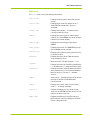
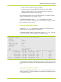
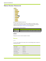
COMPLIANCE INFORMATION
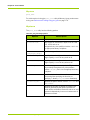
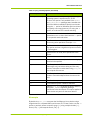
Notice
Description
FCC Class A “This device complies with Part 15 of the FCC Rules. Operation is subject to the following
Compliance two conditions: (1) This device may not cause harmful interference, and (2) this device must
accept any interference received, including interference that may cause undesired
operation.”
This equipment has been tested and found to comply with the limits for a Class A digital
device, pursuant to Part 15 of the FCC Rules. These limits are designed to provide
reasonable protection against harmful interference when the equipment is operated in a
commercial environment. This equipment generates, uses, and can radiate radio frequency
energy and, if not installed and used in accordance with the instruction manual, may cause
harmful interference to radio communications. Operation of this equipment in a residential
area is likely to cause harmful interference, in which case, you are required to correct the
interference at your own expense.
Canada
This class A digital apparatus complies with Canadian ICES-003.
Cet appareil numérique de la classe A est conforme à la norme NMB-003 du Canada.
CISPR22
Warning: This is a class A product. In a domestic environment, this product may cause
radio interference, in which case, the user may be required to take adequate remedial
measures.
Japan
HP-AM456-9002A Rev 01
VMA-series Memory Array Installation and Service Guide
3
4
VMA-series Memory Array Installation and Service Guide
HP-AM456-9002A Rev 01
Table of Contents
List of Figures . . . . . . . . . . . . . . . . . . . . . . . . . . . . . . . . . . . . . . . . . . 13
List of Tables . . . . . . . . . . . . . . . . . . . . . . . . . . . . . . . . . . . . . . . . . . . 15
Preface . . . . . . . . . . . . . . . . . . . . . . . . . . . . . . . . . . . . . . . . . . . . . . . 17
PART I.
Product Overview
CHAPTER 1.
VMA-series Overview . . . . . . . . . . . . . . . . . . . . . . . . . . . . . . . 23
Features . . . . . . . . . . . . . . . . . . . . . . . . . . . . . . . . . . . . . . . . . . . . . . . . . . . . . . . . . . . . . . . . . . . . . . . . . . . . . . . . . . . . . . . . . . 24
Physical Components . . . . . . . . . . . . . . . . . . . . . . . . . . . . . . . . . . . . . . . . . . . . . . . . . . . . . . . . . . . . . . . . . . . . . . . . . . . . . .24
Chassis . . . . . . . . . . . . . . . . . . . . . . . . . . . . . . . . . . . . . . . . . . . . . . . . . . . . . . . . . . . . . . . . . . . . . . . . . . . . . . . . . . . . . . . . . . . . . . . . . . 24
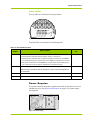
System LEDs . . . . . . . . . . . . . . . . . . . . . . . . . . . . . . . . . . . . . . . . . . . . . . . . . . . . . . . . . . . . . . . . . . . . . . . . . . . . . . . . . . . . . . . . . . . . . 25
Power Supplies. . . . . . . . . . . . . . . . . . . . . . . . . . . . . . . . . . . . . . . . . . . . . . . . . . . . . . . . . . . . . . . . . . . . . . . . . . . . . . . . . . . . . . . . . . . 27
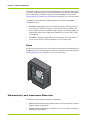
Fans. . . . . . . . . . . . . . . . . . . . . . . . . . . . . . . . . . . . . . . . . . . . . . . . . . . . . . . . . . . . . . . . . . . . . . . . . . . . . . . . . . . . . . . . . . . . . . . . . . . . . 28
Connectivity and Interfaces Overview . . . . . . . . . . . . . . . . . . . . . . . . . . . . . . . . . . . . . . . . . . . . . . . . . . . . . . . . . . . . . . . .28
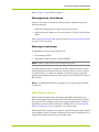
Management Interfaces. . . . . . . . . . . . . . . . . . . . . . . . . . . . . . . . . . . . . . . . . . . . . . . . . . . . . . . . . . . . . . . . . . . . . . . . . . . . . . . . . . . 29
Storage Interfaces. . . . . . . . . . . . . . . . . . . . . . . . . . . . . . . . . . . . . . . . . . . . . . . . . . . . . . . . . . . . . . . . . . . . . . . . . . . . . . . . . . . . . . . . 29
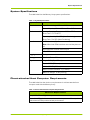
System Specifications . . . . . . . . . . . . . . . . . . . . . . . . . . . . . . . . . . . . . . . . . . . . . . . . . . . . . . . . . . . . . . . . . . . . . . . . . . . . . .31
Direct-attached Host Computer Requirements . . . . . . . . . . . . . . . . . . . . . . . . . . . . . . . . . . . . . . . . . . . . . . . . . . . . . . .31
CHAPTER 2.
Violin Intelligent Memory Modules . . . . . . . . . . . . . . . . . . . . . . 33
Violin Intelligent Memory Modules (VIMMs). . . . . . . . . . . . . . . . . . . . . . . . . . . . . . . . . . . . . . . . . . . . . . . . . . . . . . . . . . . 34
VIMM Types. . . . . . . . . . . . . . . . . . . . . . . . . . . . . . . . . . . . . . . . . . . . . . . . . . . . . . . . . . . . . . . . . . . . . . . . . . . . . . . . . . . . . . .34
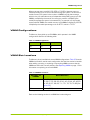
VIMM Configurations. . . . . . . . . . . . . . . . . . . . . . . . . . . . . . . . . . . . . . . . . . . . . . . . . . . . . . . . . . . . . . . . . . . . . . . . . . . . . . .35
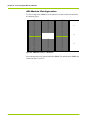
VIMM Slot Locations . . . . . . . . . . . . . . . . . . . . . . . . . . . . . . . . . . . . . . . . . . . . . . . . . . . . . . . . . . . . . . . . . . . . . . . . . . . . . . .35
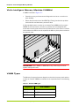
42–Module Configuration . . . . . . . . . . . . . . . . . . . . . . . . . . . . . . . . . . . . . . . . . . . . . . . . . . . . . . . . . . . . . . . . . . . . . . . . . . . . . . . . . 36
PART II.
Operation
CHAPTER 3.
Installing the Array . . . . . . . . . . . . . . . . . . . . . . . . . . . . . . . . 39
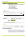
Installation and Configuration Overview . . . . . . . . . . . . . . . . . . . . . . . . . . . . . . . . . . . . . . . . . . . . . . . . . . . . . . . . . . . . . . 40
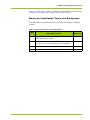
Required Installation Tools and Equipment . . . . . . . . . . . . . . . . . . . . . . . . . . . . . . . . . . . . . . . . . . . . . . . . . . . . . . . . . . . . . . . . . . 41
Rack-Mounting the Chassis . . . . . . . . . . . . . . . . . . . . . . . . . . . . . . . . . . . . . . . . . . . . . . . . . . . . . . . . . . . . . . . . . . . . . . . . . 42
Installing the Memory Array in a 19" Equipment Rack. . . . . . . . . . . . . . . . . . . . . . . . . . . . . . . . . . . . . . . . . . . . . . . . . . . . . . . . 42
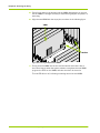
Installing the Cable Management Arm . . . . . . . . . . . . . . . . . . . . . . . . . . . . . . . . . . . . . . . . . . . . . . . . . . . . . . . . . . . . . . . . . . . . . . 43
HP-AM456-9002A Rev 01
VMA-series Memory Array Installation and Service Guide
5
Table of Contents
Connecting the PCIe Cable to the Memory Array. . . . . . . . . . . . . . . . . . . . . . . . . . . . . . . . . . . . . . . . . . . . . . . . . . . . . .46
Connecting Power . . . . . . . . . . . . . . . . . . . . . . . . . . . . . . . . . . . . . . . . . . . . . . . . . . . . . . . . . . . . . . . . . . . . . . . . . . . . . . . . .47
Power Requirements . . . . . . . . . . . . . . . . . . . . . . . . . . . . . . . . . . . . . . . . . . . . . . . . . . . . . . . . . . . . . . . . . . . . . . . . . . . . . . . . . . . . . 47
Connecting the AC Power Cords to the System . . . . . . . . . . . . . . . . . . . . . . . . . . . . . . . . . . . . . . . . . . . . . . . . . . . . . . . . . . . . . 47
Connecting Equipment Ground . . . . . . . . . . . . . . . . . . . . . . . . . . . . . . . . . . . . . . . . . . . . . . . . . . . . . . . . . . . . . . . . . . . . . . . . . . . . 48
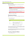
Connecting Management Network . . . . . . . . . . . . . . . . . . . . . . . . . . . . . . . . . . . . . . . . . . . . . . . . . . . . . . . . . . . . . . . . . .50
Connecting the Serial Cable . . . . . . . . . . . . . . . . . . . . . . . . . . . . . . . . . . . . . . . . . . . . . . . . . . . . . . . . . . . . . . . . . . . . . . . . . . . . . . . 50
Connecting the Ethernet Cable . . . . . . . . . . . . . . . . . . . . . . . . . . . . . . . . . . . . . . . . . . . . . . . . . . . . . . . . . . . . . . . . . . . . . . . . . . . . 51
Connecting the PCIe Cable to a Host Computer or Memory Gateway . . . . . . . . . . . . . . . . . . . . . . . . . . . . . . . . . . .53
Host Computer . . . . . . . . . . . . . . . . . . . . . . . . . . . . . . . . . . . . . . . . . . . . . . . . . . . . . . . . . . . . . . . . . . . . . . . . . . . . . . . . . . . . . . . . . . 53
Memory Gateway . . . . . . . . . . . . . . . . . . . . . . . . . . . . . . . . . . . . . . . . . . . . . . . . . . . . . . . . . . . . . . . . . . . . . . . . . . . . . . . . . . . . . . . . 54
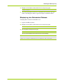
Routing the Cables onto the Cable Management Arm . . . . . . . . . . . . . . . . . . . . . . . . . . . . . . . . . . . . . . . . . . . . . . . . .55
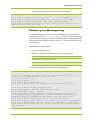
Powering up the Memory Array . . . . . . . . . . . . . . . . . . . . . . . . . . . . . . . . . . . . . . . . . . . . . . . . . . . . . . . . . . . . . . . . . . . . .56
CHAPTER 4.
Configuring the Array . . . . . . . . . . . . . . . . . . . . . . . . . . . . . . 57
Memory Array Default Settings . . . . . . . . . . . . . . . . . . . . . . . . . . . . . . . . . . . . . . . . . . . . . . . . . . . . . . . . . . . . . . . . . . . . .58
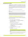
Connecting to the CLI . . . . . . . . . . . . . . . . . . . . . . . . . . . . . . . . . . . . . . . . . . . . . . . . . . . . . . . . . . . . . . . . . . . . . . . . . . . . . .59
Logging into the CLI via the Serial Interface . . . . . . . . . . . . . . . . . . . . . . . . . . . . . . . . . . . . . . . . . . . . . . . . . . . . . . . . . . . . . . . . . 59
Changing the Default System Settings . . . . . . . . . . . . . . . . . . . . . . . . . . . . . . . . . . . . . . . . . . . . . . . . . . . . . . . . . . . . . . .62
Changing the Admin Password . . . . . . . . . . . . . . . . . . . . . . . . . . . . . . . . . . . . . . . . . . . . . . . . . . . . . . . . . . . . . . . . . . . . . . . . . . . . 62
Changing the Default IP Address, Netmask, and Gateway . . . . . . . . . . . . . . . . . . . . . . . . . . . . . . . . . . . . . . . . . . . . . . . . . . . . 63
Changing the Hostname . . . . . . . . . . . . . . . . . . . . . . . . . . . . . . . . . . . . . . . . . . . . . . . . . . . . . . . . . . . . . . . . . . . . . . . . . . . . . . . . . . 64
Configuring DHCP Settings . . . . . . . . . . . . . . . . . . . . . . . . . . . . . . . . . . . . . . . . . . . . . . . . . . . . . . . . . . . . . . . . . . . . . . . . .65
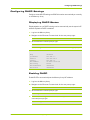
Displaying DHCP Status . . . . . . . . . . . . . . . . . . . . . . . . . . . . . . . . . . . . . . . . . . . . . . . . . . . . . . . . . . . . . . . . . . . . . . . . . . . . . . . . . . 65
Enabling DHCP. . . . . . . . . . . . . . . . . . . . . . . . . . . . . . . . . . . . . . . . . . . . . . . . . . . . . . . . . . . . . . . . . . . . . . . . . . . . . . . . . . . . . . . . . . . 65
Disabling DHCP . . . . . . . . . . . . . . . . . . . . . . . . . . . . . . . . . . . . . . . . . . . . . . . . . . . . . . . . . . . . . . . . . . . . . . . . . . . . . . . . . . . . . . . . . . 66
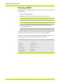
Configuring Domain Name System (DNS) . . . . . . . . . . . . . . . . . . . . . . . . . . . . . . . . . . . . . . . . . . . . . . . . . . . . . . . . . . . .67
Configuring the DNS Name . . . . . . . . . . . . . . . . . . . . . . . . . . . . . . . . . . . . . . . . . . . . . . . . . . . . . . . . . . . . . . . . . . . . . . . . . . . . . . .
Configuring the DNS Search Domain Name . . . . . . . . . . . . . . . . . . . . . . . . . . . . . . . . . . . . . . . . . . . . . . . . . . . . . . . . . . . . . . . .
Displaying the DNS Mode and Pre-provisioned Information. . . . . . . . . . . . . . . . . . . . . . . . . . . . . . . . . . . . . . . . . . . . . . . . . . .
Setting the DNS Mode. . . . . . . . . . . . . . . . . . . . . . . . . . . . . . . . . . . . . . . . . . . . . . . . . . . . . . . . . . . . . . . . . . . . . . . . . . . . . . . . . . . .
67
68
68
69
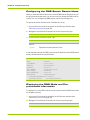
Verifying the Ethernet Connection . . . . . . . . . . . . . . . . . . . . . . . . . . . . . . . . . . . . . . . . . . . . . . . . . . . . . . . . . . . . . . . . . . .70
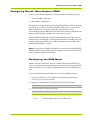
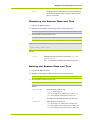
Displaying and Setting System Log (Syslog) Options . . . . . . . . . . . . . . . . . . . . . . . . . . . . . . . . . . . . . . . . . . . . . . . . . . .71
Displaying the Configured IP Address of the Syslog Host . . . . . . . . . . . . . . . . . . . . . . . . . . . . . . . . . . . . . . . . . . . . . . . . . . . . .
Setting the IP Address for the Syslog Host . . . . . . . . . . . . . . . . . . . . . . . . . . . . . . . . . . . . . . . . . . . . . . . . . . . . . . . . . . . . . . . . .
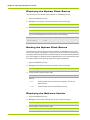
Determining the Status of the System Log Service . . . . . . . . . . . . . . . . . . . . . . . . . . . . . . . . . . . . . . . . . . . . . . . . . . . . . . . . . .
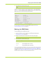
Sending the System Log to a Host . . . . . . . . . . . . . . . . . . . . . . . . . . . . . . . . . . . . . . . . . . . . . . . . . . . . . . . . . . . . . . . . . . . . . . . . .
71
72
72
73
Formatting the Memory Array . . . . . . . . . . . . . . . . . . . . . . . . . . . . . . . . . . . . . . . . . . . . . . . . . . . . . . . . . . . . . . . . . . . . . .74
CHAPTER 5.
Operating the System via the CLI . . . . . . . . . . . . . . . . . . . . . . 75
Connecting to the CLI . . . . . . . . . . . . . . . . . . . . . . . . . . . . . . . . . . . . . . . . . . . . . . . . . . . . . . . . . . . . . . . . . . . . . . . . . . . . . .76
Connecting via SSH . . . . . . . . . . . . . . . . . . . . . . . . . . . . . . . . . . . . . . . . . . . . . . . . . . . . . . . . . . . . . . . . . . . . . . . . . . . . . . . . . . . . . . 76
Connecting via Telnet. . . . . . . . . . . . . . . . . . . . . . . . . . . . . . . . . . . . . . . . . . . . . . . . . . . . . . . . . . . . . . . . . . . . . . . . . . . . . . . . . . . . . 76
Displaying and Setting the CLI Window Options . . . . . . . . . . . . . . . . . . . . . . . . . . . . . . . . . . . . . . . . . . . . . . . . . . . . . . .79
Displaying the Number of Columns . . . . . . . . . . . . . . . . . . . . . . . . . . . . . . . . . . . . . . . . . . . . . . . . . . . . . . . . . . . . . . . . . . . . . . . .
Setting the Number of Columns . . . . . . . . . . . . . . . . . . . . . . . . . . . . . . . . . . . . . . . . . . . . . . . . . . . . . . . . . . . . . . . . . . . . . . . . . . .
Displaying the Command Line Edit Mode . . . . . . . . . . . . . . . . . . . . . . . . . . . . . . . . . . . . . . . . . . . . . . . . . . . . . . . . . . . . . . . . . . .
Setting the Command Line Editor . . . . . . . . . . . . . . . . . . . . . . . . . . . . . . . . . . . . . . . . . . . . . . . . . . . . . . . . . . . . . . . . . . . . . . . . . .
Displaying the History Buffer Size . . . . . . . . . . . . . . . . . . . . . . . . . . . . . . . . . . . . . . . . . . . . . . . . . . . . . . . . . . . . . . . . . . . . . . . . . .
Setting the History Buffer Size. . . . . . . . . . . . . . . . . . . . . . . . . . . . . . . . . . . . . . . . . . . . . . . . . . . . . . . . . . . . . . . . . . . . . . . . . . . . .
Displaying the Number of Window Lines . . . . . . . . . . . . . . . . . . . . . . . . . . . . . . . . . . . . . . . . . . . . . . . . . . . . . . . . . . . . . . . . . . .
Setting the Number of Window Lines . . . . . . . . . . . . . . . . . . . . . . . . . . . . . . . . . . . . . . . . . . . . . . . . . . . . . . . . . . . . . . . . . . . . . .
Displaying the Pagination Mode . . . . . . . . . . . . . . . . . . . . . . . . . . . . . . . . . . . . . . . . . . . . . . . . . . . . . . . . . . . . . . . . . . . . . . . . . . .
Setting the Pagination Mode . . . . . . . . . . . . . . . . . . . . . . . . . . . . . . . . . . . . . . . . . . . . . . . . . . . . . . . . . . . . . . . . . . . . . . . . . . . . . .
79
79
80
80
80
81
81
81
82
82
Displaying and Setting System Information . . . . . . . . . . . . . . . . . . . . . . . . . . . . . . . . . . . . . . . . . . . . . . . . . . . . . . . . . . .83
Displaying System Status Information . . . . . . . . . . . . . . . . . . . . . . . . . . . . . . . . . . . . . . . . . . . . . . . . . . . . . . . . . . . . . . . . . . . . . . 83
Displaying the System Operational Time . . . . . . . . . . . . . . . . . . . . . . . . . . . . . . . . . . . . . . . . . . . . . . . . . . . . . . . . . . . . . . . . . . . . 84
6
VMA-series Memory Array Installation and Service Guide
HP-AM456-9002A Rev 01
Displaying the System Date and Time . . . . . . . . . . . . . . . . . . . . . . . . . . . . . . . . . . . . . . . . . . . . . . . . . . . . . . . . . . . . . . . . . . . . . . 85
Setting the System Date and Time . . . . . . . . . . . . . . . . . . . . . . . . . . . . . . . . . . . . . . . . . . . . . . . . . . . . . . . . . . . . . . . . . . . . . . . . . 85
Displaying the System Clock Source . . . . . . . . . . . . . . . . . . . . . . . . . . . . . . . . . . . . . . . . . . . . . . . . . . . . . . . . . . . . . . . . . . . . . . . . 86
Setting the System Clock Source. . . . . . . . . . . . . . . . . . . . . . . . . . . . . . . . . . . . . . . . . . . . . . . . . . . . . . . . . . . . . . . . . . . . . . . . . . . 86
Displaying the Software Version. . . . . . . . . . . . . . . . . . . . . . . . . . . . . . . . . . . . . . . . . . . . . . . . . . . . . . . . . . . . . . . . . . . . . . . . . . . . 86
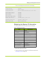
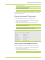
Displaying the System IP Information . . . . . . . . . . . . . . . . . . . . . . . . . . . . . . . . . . . . . . . . . . . . . . . . . . . . . . . . . . . . . . . . . . . . . . . 87
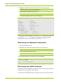
Displaying the System’s Hostname . . . . . . . . . . . . . . . . . . . . . . . . . . . . . . . . . . . . . . . . . . . . . . . . . . . . . . . . . . . . . . . . . . . . . . . . . 88
Retrieving the MAC Address. . . . . . . . . . . . . . . . . . . . . . . . . . . . . . . . . . . . . . . . . . . . . . . . . . . . . . . . . . . . . . . . . . . . . . . . . . . . . . . 88
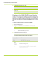
Clearing Provisioned IP Information . . . . . . . . . . . . . . . . . . . . . . . . . . . . . . . . . . . . . . . . . . . . . . . . . . . . . . . . . . . . . . . . . . . . . . . . 89
Clearing Provisioned DNS Information . . . . . . . . . . . . . . . . . . . . . . . . . . . . . . . . . . . . . . . . . . . . . . . . . . . . . . . . . . . . . . . . . . . . . . 89
Displaying the VIMM RAID Group Mapping . . . . . . . . . . . . . . . . . . . . . . . . . . . . . . . . . . . . . . . . . . . . . . . . . . . . . . . . . . . . . . . . . . 90
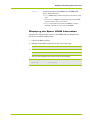
Displaying the Spare VIMM Information. . . . . . . . . . . . . . . . . . . . . . . . . . . . . . . . . . . . . . . . . . . . . . . . . . . . . . . . . . . . . . . . . . . . . 91
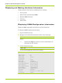
Displaying and Setting Hardware Information. . . . . . . . . . . . . . . . . . . . . . . . . . . . . . . . . . . . . . . . . . . . . . . . . . . . . . . . . 92
Displaying VIMM Configuration Information . . . . . . . . . . . . . . . . . . . . . . . . . . . . . . . . . . . . . . . . . . . . . . . . . . . . . . . . . . . . . . . . . 92
Displaying the Number of VIMMs . . . . . . . . . . . . . . . . . . . . . . . . . . . . . . . . . . . . . . . . . . . . . . . . . . . . . . . . . . . . . . . . . . . . . . . . . . 93
Displaying Fan Status . . . . . . . . . . . . . . . . . . . . . . . . . . . . . . . . . . . . . . . . . . . . . . . . . . . . . . . . . . . . . . . . . . . . . . . . . . . . . . . . . . . . . 94
Displaying Main Board Information . . . . . . . . . . . . . . . . . . . . . . . . . . . . . . . . . . . . . . . . . . . . . . . . . . . . . . . . . . . . . . . . . . . . . . . . . 95
Displaying Alarms and Logs. . . . . . . . . . . . . . . . . . . . . . . . . . . . . . . . . . . . . . . . . . . . . . . . . . . . . . . . . . . . . . . . . . . . . . . . . 96
Displaying the Current Alarms . . . . . . . . . . . . . . . . . . . . . . . . . . . . . . . . . . . . . . . . . . . . . . . . . . . . . . . . . . . . . . . . . . . . . . . . . . . . . 96
Displaying the System Log . . . . . . . . . . . . . . . . . . . . . . . . . . . . . . . . . . . . . . . . . . . . . . . . . . . . . . . . . . . . . . . . . . . . . . . . . . . . . . . . . 96
Displaying the Messages Log . . . . . . . . . . . . . . . . . . . . . . . . . . . . . . . . . . . . . . . . . . . . . . . . . . . . . . . . . . . . . . . . . . . . . . . . . . . . . . 97
Rebooting the Memory Array . . . . . . . . . . . . . . . . . . . . . . . . . . . . . . . . . . . . . . . . . . . . . . . . . . . . . . . . . . . . . . . . . . . . . . . 98
Rebooting the System. . . . . . . . . . . . . . . . . . . . . . . . . . . . . . . . . . . . . . . . . . . . . . . . . . . . . . . . . . . . . . . . . . . . . . . . . . . . . . . . . . . . . 98
Canceling a Scheduled Reboot . . . . . . . . . . . . . . . . . . . . . . . . . . . . . . . . . . . . . . . . . . . . . . . . . . . . . . . . . . . . . . . . . . . . . . . . . . . . . 98
Displaying the Scheduled Reboot . . . . . . . . . . . . . . . . . . . . . . . . . . . . . . . . . . . . . . . . . . . . . . . . . . . . . . . . . . . . . . . . . . . . . . . . . . . 99
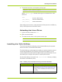
Upgrading the System Software. . . . . . . . . . . . . . . . . . . . . . . . . . . . . . . . . . . . . . . . . . . . . . . . . . . . . . . . . . . . . . . . . . . 100
Using SCP . . . . . . . . . . . . . . . . . . . . . . . . . . . . . . . . . . . . . . . . . . . . . . . . . . . . . . . . . . . . . . . . . . . . . . . . . . . . . . . . . . . . . . . . . . . . .
Restoring the Factory Default Settings . . . . . . . . . . . . . . . . . . . . . . . . . . . . . . . . . . . . . . . . . . . . . . . . . . . . . . . . . . . . . . . . . . .
Displaying the Upgrade Path. . . . . . . . . . . . . . . . . . . . . . . . . . . . . . . . . . . . . . . . . . . . . . . . . . . . . . . . . . . . . . . . . . . . . . . . . . . . .
Updating the System Software Factory Image . . . . . . . . . . . . . . . . . . . . . . . . . . . . . . . . . . . . . . . . . . . . . . . . . . . . . . . . . . . . .
CHAPTER 6.
101
103
105
105
Servicing the Array . . . . . . . . . . . . . . . . . . . . . . . . . . . . . . . 107
Guidelines for Servicing the System. . . . . . . . . . . . . . . . . . . . . . . . . . . . . . . . . . . . . . . . . . . . . . . . . . . . . . . . . . . . . . . . 108
Safety Precautions . . . . . . . . . . . . . . . . . . . . . . . . . . . . . . . . . . . . . . . . . . . . . . . . . . . . . . . . . . . . . . . . . . . . . . . . . . . . . . . . . . . . . 108
ESD Precautions . . . . . . . . . . . . . . . . . . . . . . . . . . . . . . . . . . . . . . . . . . . . . . . . . . . . . . . . . . . . . . . . . . . . . . . . . . . . . . . . . . . . . . . 108
Testing the LEDs. . . . . . . . . . . . . . . . . . . . . . . . . . . . . . . . . . . . . . . . . . . . . . . . . . . . . . . . . . . . . . . . . . . . . . . . . . . . . . . . . 109
Displaying the Status of the System LEDs . . . . . . . . . . . . . . . . . . . . . . . . . . . . . . . . . . . . . . . . . . . . . . . . . . . . . . . . . . . . . . . . .
Testing the System LEDs . . . . . . . . . . . . . . . . . . . . . . . . . . . . . . . . . . . . . . . . . . . . . . . . . . . . . . . . . . . . . . . . . . . . . . . . . . . . . . . .
Displaying the Status of the VIMM LEDs . . . . . . . . . . . . . . . . . . . . . . . . . . . . . . . . . . . . . . . . . . . . . . . . . . . . . . . . . . . . . . . . . .
Testing the VIMM LEDs . . . . . . . . . . . . . . . . . . . . . . . . . . . . . . . . . . . . . . . . . . . . . . . . . . . . . . . . . . . . . . . . . . . . . . . . . . . . . . . . .
109
109
109
110
Replacing the Fans. . . . . . . . . . . . . . . . . . . . . . . . . . . . . . . . . . . . . . . . . . . . . . . . . . . . . . . . . . . . . . . . . . . . . . . . . . . . . . . 111
Replacing the AC Power Supplies . . . . . . . . . . . . . . . . . . . . . . . . . . . . . . . . . . . . . . . . . . . . . . . . . . . . . . . . . . . . . . . . . 112
Replacing VIMMs . . . . . . . . . . . . . . . . . . . . . . . . . . . . . . . . . . . . . . . . . . . . . . . . . . . . . . . . . . . . . . . . . . . . . . . . . . . . . . . . 113
PART III.
Host Utilities
CHAPTER 7.
Linux Drivers. . . . . . . . . . . . . . . . . . . . . . . . . . . . . . . . . . . . 117
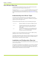
Linux Drivers Overview . . . . . . . . . . . . . . . . . . . . . . . . . . . . . . . . . . . . . . . . . . . . . . . . . . . . . . . . . . . . . . . . . . . . . . . . . . . 118
Understanding Linux Driver Types. . . . . . . . . . . . . . . . . . . . . . . . . . . . . . . . . . . . . . . . . . . . . . . . . . . . . . . . . . . . . . . . . . . . . . . . 118
Installation and Configuration Overview . . . . . . . . . . . . . . . . . . . . . . . . . . . . . . . . . . . . . . . . . . . . . . . . . . . . . . . . . . . . . . . . . . . 118
Installing Linux Driver Prerequisites . . . . . . . . . . . . . . . . . . . . . . . . . . . . . . . . . . . . . . . . . . . . . . . . . . . . . . . . . . . . . . . 119
Kernel Development Package. . . . . . . . . . . . . . . . . . . . . . . . . . . . . . . . . . . . . . . . . . . . . . . . . . . . . . . . . . . . . . . . . . . . . . . . . . . . 119
GCC Compiler . . . . . . . . . . . . . . . . . . . . . . . . . . . . . . . . . . . . . . . . . . . . . . . . . . . . . . . . . . . . . . . . . . . . . . . . . . . . . . . . . . . . . . . . . . 120
Libaio Development Package . . . . . . . . . . . . . . . . . . . . . . . . . . . . . . . . . . . . . . . . . . . . . . . . . . . . . . . . . . . . . . . . . . . . . . . . . . . . 120
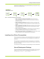
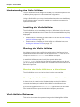
Installing Linux Drivers . . . . . . . . . . . . . . . . . . . . . . . . . . . . . . . . . . . . . . . . . . . . . . . . . . . . . . . . . . . . . . . . . . . . . . . . . . . 120
Installing Linux Drivers . . . . . . . . . . . . . . . . . . . . . . . . . . . . . . . . . . . . . . . . . . . . . . . . . . . . . . . . . . . . . . . . . . . . . . . . . . . . . . . . . . 121
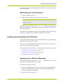
Removing the Linux Drivers. . . . . . . . . . . . . . . . . . . . . . . . . . . . . . . . . . . . . . . . . . . . . . . . . . . . . . . . . . . . . . . . . . . . . . . . . . . . . . 125
Loading and Unloading Linux Drivers. . . . . . . . . . . . . . . . . . . . . . . . . . . . . . . . . . . . . . . . . . . . . . . . . . . . . . . . . . . . . . . 125
HP-AM456-9002A Rev 01
VMA-series Memory Array Installation and Service Guide
7
Table of Contents
Loading Linux Drivers Manually . . . . . . . . . . . . . . . . . . . . . . . . . . . . . . . . . . . . . . . . . . . . . . . . . . . . . . . . . . . . . . . . . . . . . . . . . . . 125
Loading Linux Drivers as Modules . . . . . . . . . . . . . . . . . . . . . . . . . . . . . . . . . . . . . . . . . . . . . . . . . . . . . . . . . . . . . . . . . . . . . . . . 126
Unloading the Linux Driver . . . . . . . . . . . . . . . . . . . . . . . . . . . . . . . . . . . . . . . . . . . . . . . . . . . . . . . . . . . . . . . . . . . . . . . . . . . . . . . 127
Installing the Violin Utilities . . . . . . . . . . . . . . . . . . . . . . . . . . . . . . . . . . . . . . . . . . . . . . . . . . . . . . . . . . . . . . . . . . . . . . . . 127
Installing the Violin Utilities on Linux Hosts . . . . . . . . . . . . . . . . . . . . . . . . . . . . . . . . . . . . . . . . . . . . . . . . . . . . . . . . . . . . . . . . . 128
Configuring Partitions and Storage Devices . . . . . . . . . . . . . . . . . . . . . . . . . . . . . . . . . . . . . . . . . . . . . . . . . . . . . . . . 129
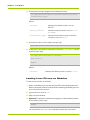
Creating Block Device Partitions. . . . . . . . . . . . . . . . . . . . . . . . . . . . . . . . . . . . . . . . . . . . . . . . . . . . . . . . . . . . . . . . . . . . . . . . . . 129
Enabling Host to Automatically Mount Partitions . . . . . . . . . . . . . . . . . . . . . . . . . . . . . . . . . . . . . . . . . . . . . . . . . . . . . . . . . . . 133
CHAPTER 8.
Windows Drivers . . . . . . . . . . . . . . . . . . . . . . . . . . . . . . . . 135
Windows Driver Overview . . . . . . . . . . . . . . . . . . . . . . . . . . . . . . . . . . . . . . . . . . . . . . . . . . . . . . . . . . . . . . . . . . . . . . . . 136
Installation and Configuration Overview. . . . . . . . . . . . . . . . . . . . . . . . . . . . . . . . . . . . . . . . . . . . . . . . . . . . . . . . . . . . . . . . . . . . 136
Installing Prerequisites . . . . . . . . . . . . . . . . . . . . . . . . . . . . . . . . . . . . . . . . . . . . . . . . . . . . . . . . . . . . . . . . . . . . . . . . . . . 136
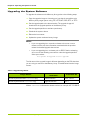
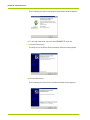
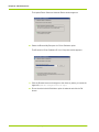
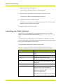
Installing Windows Drivers. . . . . . . . . . . . . . . . . . . . . . . . . . . . . . . . . . . . . . . . . . . . . . . . . . . . . . . . . . . . . . . . . . . . . . . . 137
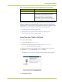
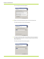
Installing the Windows Drivers . . . . . . . . . . . . . . . . . . . . . . . . . . . . . . . . . . . . . . . . . . . . . . . . . . . . . . . . . . . . . . . . . . . . . . . . . . . 137
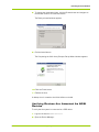
Manually Installing the Windows Drivers . . . . . . . . . . . . . . . . . . . . . . . . . . . . . . . . . . . . . . . . . . . . . . . . . . . . . . . . . . . . . . . . . . 141
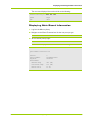
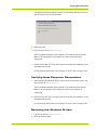
Verifying Host Computer Connections. . . . . . . . . . . . . . . . . . . . . . . . . . . . . . . . . . . . . . . . . . . . . . . . . . . . . . . . . . . . . . . . . . . . . 143
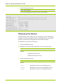
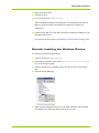
Removing the Windows Drivers . . . . . . . . . . . . . . . . . . . . . . . . . . . . . . . . . . . . . . . . . . . . . . . . . . . . . . . . . . . . . . . . . . . . . . . . . . 143
Installing the Violin Utilities . . . . . . . . . . . . . . . . . . . . . . . . . . . . . . . . . . . . . . . . . . . . . . . . . . . . . . . . . . . . . . . . . . . . . . . . 144
Installing the Violin Utilities . . . . . . . . . . . . . . . . . . . . . . . . . . . . . . . . . . . . . . . . . . . . . . . . . . . . . . . . . . . . . . . . . . . . . . . . . . . . . . . 145
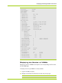
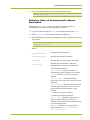
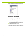
Verifying Devices Are Attached As SCSI Devices . . . . . . . . . . . . . . . . . . . . . . . . . . . . . . . . . . . . . . . . . . . . . . . . . . . . . . . . . . . 147
Expand the Disk Drives node to view the Memory Array SCSI Disk Device. . . . . . . . . . . . . . . . . . . . . . . . . . . . . . . . . . . . . 148
Removing the Violin Utilities . . . . . . . . . . . . . . . . . . . . . . . . . . . . . . . . . . . . . . . . . . . . . . . . . . . . . . . . . . . . . . . . . . . . . . . . . . . . . . 148
A dialog box appears confirming that the Violin Utilities have been deleted. . . . . . . . . . . . . . . . . . . . . . . . . . . . . . . . . . . . 148
CHAPTER 9.
Violin Utilities . . . . . . . . . . . . . . . . . . . . . . . . . . . . . . . . . . 149
Understanding the Violin Utilities . . . . . . . . . . . . . . . . . . . . . . . . . . . . . . . . . . . . . . . . . . . . . . . . . . . . . . . . . . . . . . . . . . 150
Installing the Violin Utilities . . . . . . . . . . . . . . . . . . . . . . . . . . . . . . . . . . . . . . . . . . . . . . . . . . . . . . . . . . . . . . . . . . . . . . . . . . . . . . . 150
Running the Violin Utilities. . . . . . . . . . . . . . . . . . . . . . . . . . . . . . . . . . . . . . . . . . . . . . . . . . . . . . . . . . . . . . . . . . . . . . . . . . . . . . . . 150
Violin Utilities Reference . . . . . . . . . . . . . . . . . . . . . . . . . . . . . . . . . . . . . . . . . . . . . . . . . . . . . . . . . . . . . . . . . . . . . . . . . . 150
vcounts . . . . . . . . . . . . . . . . . . . . . . . . . . . . . . . . . . . . . . . . . . . . . . . . . . . . . . . . . . . . . . . . . . . . . . . . . . . . . . . . . . . . . . . . . . . . . . . . 151
veeprom . . . . . . . . . . . . . . . . . . . . . . . . . . . . . . . . . . . . . . . . . . . . . . . . . . . . . . . . . . . . . . . . . . . . . . . . . . . . . . . . . . . . . . . . . . . . . . . 153
vhelp . . . . . . . . . . . . . . . . . . . . . . . . . . . . . . . . . . . . . . . . . . . . . . . . . . . . . . . . . . . . . . . . . . . . . . . . . . . . . . . . . . . . . . . . . . . . . . . . . . . 155
vincident . . . . . . . . . . . . . . . . . . . . . . . . . . . . . . . . . . . . . . . . . . . . . . . . . . . . . . . . . . . . . . . . . . . . . . . . . . . . . . . . . . . . . . . . . . . . . . . 155
vinfo . . . . . . . . . . . . . . . . . . . . . . . . . . . . . . . . . . . . . . . . . . . . . . . . . . . . . . . . . . . . . . . . . . . . . . . . . . . . . . . . . . . . . . . . . . . . . . . . . . . 156
vpartial. . . . . . . . . . . . . . . . . . . . . . . . . . . . . . . . . . . . . . . . . . . . . . . . . . . . . . . . . . . . . . . . . . . . . . . . . . . . . . . . . . . . . . . . . . . . . . . . . 158
vring . . . . . . . . . . . . . . . . . . . . . . . . . . . . . . . . . . . . . . . . . . . . . . . . . . . . . . . . . . . . . . . . . . . . . . . . . . . . . . . . . . . . . . . . . . . . . . . . . . . 159
vstat . . . . . . . . . . . . . . . . . . . . . . . . . . . . . . . . . . . . . . . . . . . . . . . . . . . . . . . . . . . . . . . . . . . . . . . . . . . . . . . . . . . . . . . . . . . . . . . . . . . 160
vupdate_tz . . . . . . . . . . . . . . . . . . . . . . . . . . . . . . . . . . . . . . . . . . . . . . . . . . . . . . . . . . . . . . . . . . . . . . . . . . . . . . . . . . . . . . . . . . . . . 162
vzero. . . . . . . . . . . . . . . . . . . . . . . . . . . . . . . . . . . . . . . . . . . . . . . . . . . . . . . . . . . . . . . . . . . . . . . . . . . . . . . . . . . . . . . . . . . . . . . . . . . 163
perf_test . . . . . . . . . . . . . . . . . . . . . . . . . . . . . . . . . . . . . . . . . . . . . . . . . . . . . . . . . . . . . . . . . . . . . . . . . . . . . . . . . . . . . . . . . . . . . . . 163
CHAPTER 10. Performance Tuning and Troubleshooting . . . . . . . . . . . . . . . . 167
Performance Tuning and Testing Overview . . . . . . . . . . . . . . . . . . . . . . . . . . . . . . . . . . . . . . . . . . . . . . . . . . . . . . . . . 168
Flash-Layer Performance Tuning . . . . . . . . . . . . . . . . . . . . . . . . . . . . . . . . . . . . . . . . . . . . . . . . . . . . . . . . . . . . . . . . . . 169
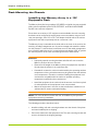
Memory Array Flash 4kB Alignment . . . . . . . . . . . . . . . . . . . . . . . . . . . . . . . . . . . . . . . . . . . . . . . . . . . . . . . . . . . . . . . . . . . . . . 169
Network-Layer Performance Testing . . . . . . . . . . . . . . . . . . . . . . . . . . . . . . . . . . . . . . . . . . . . . . . . . . . . . . . . . . . . . . 172
Preliminary Network-Layer Checks. . . . . . . . . . . . . . . . . . . . . . . . . . . . . . . . . . . . . . . . . . . . . . . . . . . . . . . . . . . . . . . . . . . . . . . . 173
Performance Testing Using perf_test . . . . . . . . . . . . . . . . . . . . . . . . . . . . . . . . . . . . . . . . . . . . . . . . . . . . . . . . . . . . . . . . . . . . . 174
APPENDIX A.
Product Models . . . . . . . . . . . . . . . . . . . . . . . . . . . . . 179
APPENDIX B.
Compliance Information . . . . . . . . . . . . . . . . . . . . . . . . 181
Regulatory Information . . . . . . . . . . . . . . . . . . . . . . . . . . . . . . . . . . . . . . . . . . . . . . . . . . . . . . . . . . . . . . . . . . . . . . . . . . . 182
Regulatory Model Number. . . . . . . . . . . . . . . . . . . . . . . . . . . . . . . . . . . . . . . . . . . . . . . . . . . . . . . . . . . . . . . . . . . . . . . . 182
Electrical Safety. . . . . . . . . . . . . . . . . . . . . . . . . . . . . . . . . . . . . . . . . . . . . . . . . . . . . . . . . . . . . . . . . . . . . . . . . . . . . . . . . . 182
Installation Conditions . . . . . . . . . . . . . . . . . . . . . . . . . . . . . . . . . . . . . . . . . . . . . . . . . . . . . . . . . . . . . . . . . . . . . . . . . . . . . . . . . . . 182
8
VMA-series Memory Array Installation and Service Guide
HP-AM456-9002A Rev 01
Network Connected Equipment . . . . . . . . . . . . . . . . . . . . . . . . . . . . . . . . . . . . . . . . . . . . . . . . . . . . . . . . . . . . . . . . . . . . . . . . . . 182
Electrostatic Discharge (ESD) Precautions . . . . . . . . . . . . . . . . . . . . . . . . . . . . . . . . . . . . . . . . . . . . . . . . . . . . . . . . .
Lithium Battery Caution . . . . . . . . . . . . . . . . . . . . . . . . . . . . . . . . . . . . . . . . . . . . . . . . . . . . . . . . . . . . . . . . . . . . . . . . . .
Cabinet Safety Precautions . . . . . . . . . . . . . . . . . . . . . . . . . . . . . . . . . . . . . . . . . . . . . . . . . . . . . . . . . . . . . . . . . . . . . . .
Disposal of Waste Equipment by Users in Private Households in the European Union . . . . . . . . . . . . . . . . . .
Perchlorate Material - Special Handling May Apply . . . . . . . . . . . . . . . . . . . . . . . . . . . . . . . . . . . . . . . . . . . . . . . . . .
European Union RFI Statement . . . . . . . . . . . . . . . . . . . . . . . . . . . . . . . . . . . . . . . . . . . . . . . . . . . . . . . . . . . . . . . . . . .
USA Radio Frequency Interference FCC Notice . . . . . . . . . . . . . . . . . . . . . . . . . . . . . . . . . . . . . . . . . . . . . . . . . . . . .
Japan Radio Frequency Interference VCCI . . . . . . . . . . . . . . . . . . . . . . . . . . . . . . . . . . . . . . . . . . . . . . . . . . . . . . . . .
Korea RFI Statement. . . . . . . . . . . . . . . . . . . . . . . . . . . . . . . . . . . . . . . . . . . . . . . . . . . . . . . . . . . . . . . . . . . . . . . . . . . . .
Canada RFI Statement . . . . . . . . . . . . . . . . . . . . . . . . . . . . . . . . . . . . . . . . . . . . . . . . . . . . . . . . . . . . . . . . . . . . . . . . . . .
Australia C-Tick Label . . . . . . . . . . . . . . . . . . . . . . . . . . . . . . . . . . . . . . . . . . . . . . . . . . . . . . . . . . . . . . . . . . . . . . . . . . . .
APPENDIX C.
182
183
183
184
184
184
184
185
185
185
185
Alarm Reference. . . . . . . . . . . . . . . . . . . . . . . . . . . . . 187
Understanding Memory Array Alarms . . . . . . . . . . . . . . . . . . . . . . . . . . . . . . . . . . . . . . . . . . . . . . . . . . . . . . . . . . . . . 188
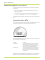
Interpreting Alarm LEDs . . . . . . . . . . . . . . . . . . . . . . . . . . . . . . . . . . . . . . . . . . . . . . . . . . . . . . . . . . . . . . . . . . . . . . . . . . . . . . . . 188
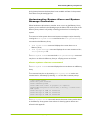
Understanding System Alarm and System Message Commands. . . . . . . . . . . . . . . . . . . . . . . . . . . . . . . . . . . . . . . . . . . . 189
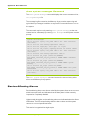
Service-Affecting Alarms . . . . . . . . . . . . . . . . . . . . . . . . . . . . . . . . . . . . . . . . . . . . . . . . . . . . . . . . . . . . . . . . . . . . . . . . . 190
Equipment Service-Affecting Alarms . . . . . . . . . . . . . . . . . . . . . . . . . . . . . . . . . . . . . . . . . . . . . . . . . . . . . . . . . . . . . . . . . . . . . .
Flash Service-Affecting Alarms. . . . . . . . . . . . . . . . . . . . . . . . . . . . . . . . . . . . . . . . . . . . . . . . . . . . . . . . . . . . . . . . . . . . . . . . . . .
Port Service-Affecting Alarms. . . . . . . . . . . . . . . . . . . . . . . . . . . . . . . . . . . . . . . . . . . . . . . . . . . . . . . . . . . . . . . . . . . . . . . . . . . .
Power Service-Affecting Alarms. . . . . . . . . . . . . . . . . . . . . . . . . . . . . . . . . . . . . . . . . . . . . . . . . . . . . . . . . . . . . . . . . . . . . . . . . .
RAID Service-Affecting Alarms . . . . . . . . . . . . . . . . . . . . . . . . . . . . . . . . . . . . . . . . . . . . . . . . . . . . . . . . . . . . . . . . . . . . . . . . . . .
System Service-Affecting Alarms. . . . . . . . . . . . . . . . . . . . . . . . . . . . . . . . . . . . . . . . . . . . . . . . . . . . . . . . . . . . . . . . . . . . . . . . .
Temperature Service-Affecting Alarms . . . . . . . . . . . . . . . . . . . . . . . . . . . . . . . . . . . . . . . . . . . . . . . . . . . . . . . . . . . . . . . . . . .
VIMM Service-Affecting Alarms . . . . . . . . . . . . . . . . . . . . . . . . . . . . . . . . . . . . . . . . . . . . . . . . . . . . . . . . . . . . . . . . . . . . . . . . . .
191
191
192
192
193
194
195
196
Non-Service Affecting Alarms . . . . . . . . . . . . . . . . . . . . . . . . . . . . . . . . . . . . . . . . . . . . . . . . . . . . . . . . . . . . . . . . . . . . . 196
Temperature Non-Service Affecting Alarms . . . . . . . . . . . . . . . . . . . . . . . . . . . . . . . . . . . . . . . . . . . . . . . . . . . . . . . . . . . . . . .
Equipment Non-Service Affecting Alarms . . . . . . . . . . . . . . . . . . . . . . . . . . . . . . . . . . . . . . . . . . . . . . . . . . . . . . . . . . . . . . . . .
Flash Non-Service Affecting Alarms . . . . . . . . . . . . . . . . . . . . . . . . . . . . . . . . . . . . . . . . . . . . . . . . . . . . . . . . . . . . . . . . . . . . . .
Port Non-Service Affecting Alarms . . . . . . . . . . . . . . . . . . . . . . . . . . . . . . . . . . . . . . . . . . . . . . . . . . . . . . . . . . . . . . . . . . . . . . .
Power Non-Service Affecting Alarms . . . . . . . . . . . . . . . . . . . . . . . . . . . . . . . . . . . . . . . . . . . . . . . . . . . . . . . . . . . . . . . . . . . . .
RAID Non-Service Affecting Alarms . . . . . . . . . . . . . . . . . . . . . . . . . . . . . . . . . . . . . . . . . . . . . . . . . . . . . . . . . . . . . . . . . . . . . .
VIMM Non-Service Affecting Alarms. . . . . . . . . . . . . . . . . . . . . . . . . . . . . . . . . . . . . . . . . . . . . . . . . . . . . . . . . . . . . . . . . . . . . .
APPENDIX D.
197
198
199
200
201
202
202
CLI Reference . . . . . . . . . . . . . . . . . . . . . . . . . . . . . . 209
Context Navigation . . . . . . . . . . . . . . . . . . . . . . . . . . . . . . . . . . . . . . . . . . . . . . . . . . . . . . . . . . . . . . . . . . . . . . . . . . . . . . . 211
Typing CLI Commands . . . . . . . . . . . . . . . . . . . . . . . . . . . . . . . . . . . . . . . . . . . . . . . . . . . . . . . . . . . . . . . . . . . . . . . . . . . . . . . . . . 211
General Commands. . . . . . . . . . . . . . . . . . . . . . . . . . . . . . . . . . . . . . . . . . . . . . . . . . . . . . . . . . . . . . . . . . . . . . . . . . . . . . 213
cancel . . . . . . . . . . . . . . . . . . . . . . . . . . . . . . . . . . . . . . . . . . . . . . . . . . . . . . . . . . . . . . . . . . . . . . . . . . . . . . . . . . . . . . . . . . . . . . . . .
clear . . . . . . . . . . . . . . . . . . . . . . . . . . . . . . . . . . . . . . . . . . . . . . . . . . . . . . . . . . . . . . . . . . . . . . . . . . . . . . . . . . . . . . . . . . . . . . . . . .
context . . . . . . . . . . . . . . . . . . . . . . . . . . . . . . . . . . . . . . . . . . . . . . . . . . . . . . . . . . . . . . . . . . . . . . . . . . . . . . . . . . . . . . . . . . . . . . . .
exit . . . . . . . . . . . . . . . . . . . . . . . . . . . . . . . . . . . . . . . . . . . . . . . . . . . . . . . . . . . . . . . . . . . . . . . . . . . . . . . . . . . . . . . . . . . . . . . . . . . .
format. . . . . . . . . . . . . . . . . . . . . . . . . . . . . . . . . . . . . . . . . . . . . . . . . . . . . . . . . . . . . . . . . . . . . . . . . . . . . . . . . . . . . . . . . . . . . . . . .
help . . . . . . . . . . . . . . . . . . . . . . . . . . . . . . . . . . . . . . . . . . . . . . . . . . . . . . . . . . . . . . . . . . . . . . . . . . . . . . . . . . . . . . . . . . . . . . . . . . .
history. . . . . . . . . . . . . . . . . . . . . . . . . . . . . . . . . . . . . . . . . . . . . . . . . . . . . . . . . . . . . . . . . . . . . . . . . . . . . . . . . . . . . . . . . . . . . . . . .
ping . . . . . . . . . . . . . . . . . . . . . . . . . . . . . . . . . . . . . . . . . . . . . . . . . . . . . . . . . . . . . . . . . . . . . . . . . . . . . . . . . . . . . . . . . . . . . . . . . . .
reboot . . . . . . . . . . . . . . . . . . . . . . . . . . . . . . . . . . . . . . . . . . . . . . . . . . . . . . . . . . . . . . . . . . . . . . . . . . . . . . . . . . . . . . . . . . . . . . . . .
reset . . . . . . . . . . . . . . . . . . . . . . . . . . . . . . . . . . . . . . . . . . . . . . . . . . . . . . . . . . . . . . . . . . . . . . . . . . . . . . . . . . . . . . . . . . . . . . . . . .
set . . . . . . . . . . . . . . . . . . . . . . . . . . . . . . . . . . . . . . . . . . . . . . . . . . . . . . . . . . . . . . . . . . . . . . . . . . . . . . . . . . . . . . . . . . . . . . . . . . . .
show . . . . . . . . . . . . . . . . . . . . . . . . . . . . . . . . . . . . . . . . . . . . . . . . . . . . . . . . . . . . . . . . . . . . . . . . . . . . . . . . . . . . . . . . . . . . . . . . . .
shutdown . . . . . . . . . . . . . . . . . . . . . . . . . . . . . . . . . . . . . . . . . . . . . . . . . . . . . . . . . . . . . . . . . . . . . . . . . . . . . . . . . . . . . . . . . . . . . .
top . . . . . . . . . . . . . . . . . . . . . . . . . . . . . . . . . . . . . . . . . . . . . . . . . . . . . . . . . . . . . . . . . . . . . . . . . . . . . . . . . . . . . . . . . . . . . . . . . . . .
up. . . . . . . . . . . . . . . . . . . . . . . . . . . . . . . . . . . . . . . . . . . . . . . . . . . . . . . . . . . . . . . . . . . . . . . . . . . . . . . . . . . . . . . . . . . . . . . . . . . . .
?. . . . . . . . . . . . . . . . . . . . . . . . . . . . . . . . . . . . . . . . . . . . . . . . . . . . . . . . . . . . . . . . . . . . . . . . . . . . . . . . . . . . . . . . . . . . . . . . . . . . . .
213
214
214
215
215
216
216
217
217
218
218
218
219
219
220
220
Chassis Context Commands . . . . . . . . . . . . . . . . . . . . . . . . . . . . . . . . . . . . . . . . . . . . . . . . . . . . . . . . . . . . . . . . . . . . . . 221
context board 0 . . . . . . . . . . . . . . . . . . . . . . . . . . . . . . . . . . . . . . . . . . . . . . . . . . . . . . . . . . . . . . . . . . . . . . . . . . . . . . . . . . . . . . . . 221
HP-AM456-9002A Rev 01
VMA-series Memory Array Installation and Service Guide
9
Table of Contents
context controller . . . . . . . . . . . . . . . . . . . . . . . . . . . . . . . . . . . . . . . . . . . . . . . . . . . . . . . . . . . . . . . . . . . . . . . . . . . . . . . . . . . . . . . 221
context fan-tray . . . . . . . . . . . . . . . . . . . . . . . . . . . . . . . . . . . . . . . . . . . . . . . . . . . . . . . . . . . . . . . . . . . . . . . . . . . . . . . . . . . . . . . . . 222
Board 0 Context Commands. . . . . . . . . . . . . . . . . . . . . . . . . . . . . . . . . . . . . . . . . . . . . . . . . . . . . . . . . . . . . . . . . . . . . . 223
context slot. . . . . . . . . . . . . . . . . . . . . . . . . . . . . . . . . . . . . . . . . . . . . . . . . . . . . . . . . . . . . . . . . . . . . . . . . . . . . . . . . . . . . . . . . . . . . 223
set flash-scrubbing . . . . . . . . . . . . . . . . . . . . . . . . . . . . . . . . . . . . . . . . . . . . . . . . . . . . . . . . . . . . . . . . . . . . . . . . . . . . . . . . . . . . . . 224
show flash-scrubbing . . . . . . . . . . . . . . . . . . . . . . . . . . . . . . . . . . . . . . . . . . . . . . . . . . . . . . . . . . . . . . . . . . . . . . . . . . . . . . . . . . . . 225
show info . . . . . . . . . . . . . . . . . . . . . . . . . . . . . . . . . . . . . . . . . . . . . . . . . . . . . . . . . . . . . . . . . . . . . . . . . . . . . . . . . . . . . . . . . . . . . . . 225
set write-buffer . . . . . . . . . . . . . . . . . . . . . . . . . . . . . . . . . . . . . . . . . . . . . . . . . . . . . . . . . . . . . . . . . . . . . . . . . . . . . . . . . . . . . . . . . 225
Slot Context Commands . . . . . . . . . . . . . . . . . . . . . . . . . . . . . . . . . . . . . . . . . . . . . . . . . . . . . . . . . . . . . . . . . . . . . . . . . . 227
context vimm . . . . . . . . . . . . . . . . . . . . . . . . . . . . . . . . . . . . . . . . . . . . . . . . . . . . . . . . . . . . . . . . . . . . . . . . . . . . . . . . . . . . . . . . . . . 227
set led-test . . . . . . . . . . . . . . . . . . . . . . . . . . . . . . . . . . . . . . . . . . . . . . . . . . . . . . . . . . . . . . . . . . . . . . . . . . . . . . . . . . . . . . . . . . . . . 228
show led-state . . . . . . . . . . . . . . . . . . . . . . . . . . . . . . . . . . . . . . . . . . . . . . . . . . . . . . . . . . . . . . . . . . . . . . . . . . . . . . . . . . . . . . . . . . 228
VIMM Context Commands. . . . . . . . . . . . . . . . . . . . . . . . . . . . . . . . . . . . . . . . . . . . . . . . . . . . . . . . . . . . . . . . . . . . . . . . 230
set admin-state . . . . . . . . . . . . . . . . . . . . . . . . . . . . . . . . . . . . . . . . . . . . . . . . . . . . . . . . . . . . . . . . . . . . . . . . . . . . . . . . . . . . . . . . . 230
show. . . . . . . . . . . . . . . . . . . . . . . . . . . . . . . . . . . . . . . . . . . . . . . . . . . . . . . . . . . . . . . . . . . . . . . . . . . . . . . . . . . . . . . . . . . . . . . . . . . 231
VIMM-summary Context Commands . . . . . . . . . . . . . . . . . . . . . . . . . . . . . . . . . . . . . . . . . . . . . . . . . . . . . . . . . . . . . . 233
show. . . . . . . . . . . . . . . . . . . . . . . . . . . . . . . . . . . . . . . . . . . . . . . . . . . . . . . . . . . . . . . . . . . . . . . . . . . . . . . . . . . . . . . . . . . . . . . . . . . 233
Controller Context Commands . . . . . . . . . . . . . . . . . . . . . . . . . . . . . . . . . . . . . . . . . . . . . . . . . . . . . . . . . . . . . . . . . . . . 236
set serial-speed . . . . . . . . . . . . . . . . . . . . . . . . . . . . . . . . . . . . . . . . . . . . . . . . . . . . . . . . . . . . . . . . . . . . . . . . . . . . . . . . . . . . . . . . . 236
show serial-speed . . . . . . . . . . . . . . . . . . . . . . . . . . . . . . . . . . . . . . . . . . . . . . . . . . . . . . . . . . . . . . . . . . . . . . . . . . . . . . . . . . . . . . . 236
context ethernet 0 . . . . . . . . . . . . . . . . . . . . . . . . . . . . . . . . . . . . . . . . . . . . . . . . . . . . . . . . . . . . . . . . . . . . . . . . . . . . . . . . . . . . . . 237
Ethernet 0 Context Commands . . . . . . . . . . . . . . . . . . . . . . . . . . . . . . . . . . . . . . . . . . . . . . . . . . . . . . . . . . . . . . . . . . . 238
set dhcp . . . . . . . . . . . . . . . . . . . . . . . . . . . . . . . . . . . . . . . . . . . . . . . . . . . . . . . . . . . . . . . . . . . . . . . . . . . . . . . . . . . . . . . . . . . . . . . 238
set ip-address . . . . . . . . . . . . . . . . . . . . . . . . . . . . . . . . . . . . . . . . . . . . . . . . . . . . . . . . . . . . . . . . . . . . . . . . . . . . . . . . . . . . . . . . . . 239
clear ip-address. . . . . . . . . . . . . . . . . . . . . . . . . . . . . . . . . . . . . . . . . . . . . . . . . . . . . . . . . . . . . . . . . . . . . . . . . . . . . . . . . . . . . . . . . 239
set dns-config. . . . . . . . . . . . . . . . . . . . . . . . . . . . . . . . . . . . . . . . . . . . . . . . . . . . . . . . . . . . . . . . . . . . . . . . . . . . . . . . . . . . . . . . . . . 239
set dns-nameserver . . . . . . . . . . . . . . . . . . . . . . . . . . . . . . . . . . . . . . . . . . . . . . . . . . . . . . . . . . . . . . . . . . . . . . . . . . . . . . . . . . . . . 240
clear dns-nameserver . . . . . . . . . . . . . . . . . . . . . . . . . . . . . . . . . . . . . . . . . . . . . . . . . . . . . . . . . . . . . . . . . . . . . . . . . . . . . . . . . . . 240
set dns-search. . . . . . . . . . . . . . . . . . . . . . . . . . . . . . . . . . . . . . . . . . . . . . . . . . . . . . . . . . . . . . . . . . . . . . . . . . . . . . . . . . . . . . . . . . 240
clear dns-search . . . . . . . . . . . . . . . . . . . . . . . . . . . . . . . . . . . . . . . . . . . . . . . . . . . . . . . . . . . . . . . . . . . . . . . . . . . . . . . . . . . . . . . . 241
show. . . . . . . . . . . . . . . . . . . . . . . . . . . . . . . . . . . . . . . . . . . . . . . . . . . . . . . . . . . . . . . . . . . . . . . . . . . . . . . . . . . . . . . . . . . . . . . . . . . 241
reset. . . . . . . . . . . . . . . . . . . . . . . . . . . . . . . . . . . . . . . . . . . . . . . . . . . . . . . . . . . . . . . . . . . . . . . . . . . . . . . . . . . . . . . . . . . . . . . . . . . 242
Fan-tray Context Commands . . . . . . . . . . . . . . . . . . . . . . . . . . . . . . . . . . . . . . . . . . . . . . . . . . . . . . . . . . . . . . . . . . . . . . 243
context fan . . . . . . . . . . . . . . . . . . . . . . . . . . . . . . . . . . . . . . . . . . . . . . . . . . . . . . . . . . . . . . . . . . . . . . . . . . . . . . . . . . . . . . . . . . . . . 243
Fan Context Commands . . . . . . . . . . . . . . . . . . . . . . . . . . . . . . . . . . . . . . . . . . . . . . . . . . . . . . . . . . . . . . . . . . . . . . . . . . 244
show. . . . . . . . . . . . . . . . . . . . . . . . . . . . . . . . . . . . . . . . . . . . . . . . . . . . . . . . . . . . . . . . . . . . . . . . . . . . . . . . . . . . . . . . . . . . . . . . . . . 244
CLI Context Commands . . . . . . . . . . . . . . . . . . . . . . . . . . . . . . . . . . . . . . . . . . . . . . . . . . . . . . . . . . . . . . . . . . . . . . . . . . 245
set columns . . . . . . . . . . . . . . . . . . . . . . . . . . . . . . . . . . . . . . . . . . . . . . . . . . . . . . . . . . . . . . . . . . . . . . . . . . . . . . . . . . . . . . . . . . . . 245
set edit-mode . . . . . . . . . . . . . . . . . . . . . . . . . . . . . . . . . . . . . . . . . . . . . . . . . . . . . . . . . . . . . . . . . . . . . . . . . . . . . . . . . . . . . . . . . . . 246
set history-size . . . . . . . . . . . . . . . . . . . . . . . . . . . . . . . . . . . . . . . . . . . . . . . . . . . . . . . . . . . . . . . . . . . . . . . . . . . . . . . . . . . . . . . . . . 246
set idle-timeout . . . . . . . . . . . . . . . . . . . . . . . . . . . . . . . . . . . . . . . . . . . . . . . . . . . . . . . . . . . . . . . . . . . . . . . . . . . . . . . . . . . . . . . . . 246
set lines . . . . . . . . . . . . . . . . . . . . . . . . . . . . . . . . . . . . . . . . . . . . . . . . . . . . . . . . . . . . . . . . . . . . . . . . . . . . . . . . . . . . . . . . . . . . . . . . 246
set pagination . . . . . . . . . . . . . . . . . . . . . . . . . . . . . . . . . . . . . . . . . . . . . . . . . . . . . . . . . . . . . . . . . . . . . . . . . . . . . . . . . . . . . . . . . . 247
show columns . . . . . . . . . . . . . . . . . . . . . . . . . . . . . . . . . . . . . . . . . . . . . . . . . . . . . . . . . . . . . . . . . . . . . . . . . . . . . . . . . . . . . . . . . . 247
show edit-mode . . . . . . . . . . . . . . . . . . . . . . . . . . . . . . . . . . . . . . . . . . . . . . . . . . . . . . . . . . . . . . . . . . . . . . . . . . . . . . . . . . . . . . . . . 248
show history-size . . . . . . . . . . . . . . . . . . . . . . . . . . . . . . . . . . . . . . . . . . . . . . . . . . . . . . . . . . . . . . . . . . . . . . . . . . . . . . . . . . . . . . . . 248
show idle-timeout . . . . . . . . . . . . . . . . . . . . . . . . . . . . . . . . . . . . . . . . . . . . . . . . . . . . . . . . . . . . . . . . . . . . . . . . . . . . . . . . . . . . . . . 248
show lines . . . . . . . . . . . . . . . . . . . . . . . . . . . . . . . . . . . . . . . . . . . . . . . . . . . . . . . . . . . . . . . . . . . . . . . . . . . . . . . . . . . . . . . . . . . . . . 249
show pagination . . . . . . . . . . . . . . . . . . . . . . . . . . . . . . . . . . . . . . . . . . . . . . . . . . . . . . . . . . . . . . . . . . . . . . . . . . . . . . . . . . . . . . . . 249
show session . . . . . . . . . . . . . . . . . . . . . . . . . . . . . . . . . . . . . . . . . . . . . . . . . . . . . . . . . . . . . . . . . . . . . . . . . . . . . . . . . . . . . . . . . . . 249
cancel session . . . . . . . . . . . . . . . . . . . . . . . . . . . . . . . . . . . . . . . . . . . . . . . . . . . . . . . . . . . . . . . . . . . . . . . . . . . . . . . . . . . . . . . . . . 250
RAID Context Commands. . . . . . . . . . . . . . . . . . . . . . . . . . . . . . . . . . . . . . . . . . . . . . . . . . . . . . . . . . . . . . . . . . . . . . . . . 251
context group. . . . . . . . . . . . . . . . . . . . . . . . . . . . . . . . . . . . . . . . . . . . . . . . . . . . . . . . . . . . . . . . . . . . . . . . . . . . . . . . . . . . . . . . . . . 251
show spare-ids. . . . . . . . . . . . . . . . . . . . . . . . . . . . . . . . . . . . . . . . . . . . . . . . . . . . . . . . . . . . . . . . . . . . . . . . . . . . . . . . . . . . . . . . . . 252
RAID Group Context Commands . . . . . . . . . . . . . . . . . . . . . . . . . . . . . . . . . . . . . . . . . . . . . . . . . . . . . . . . . . . . . . . . . . 253
context maps . . . . . . . . . . . . . . . . . . . . . . . . . . . . . . . . . . . . . . . . . . . . . . . . . . . . . . . . . . . . . . . . . . . . . . . . . . . . . . . . . . . . . . . . . . . 253
Maps Context Commands . . . . . . . . . . . . . . . . . . . . . . . . . . . . . . . . . . . . . . . . . . . . . . . . . . . . . . . . . . . . . . . . . . . . . . . . 255
show. . . . . . . . . . . . . . . . . . . . . . . . . . . . . . . . . . . . . . . . . . . . . . . . . . . . . . . . . . . . . . . . . . . . . . . . . . . . . . . . . . . . . . . . . . . . . . . . . . . 255
10
VMA-series Memory Array Installation and Service Guide
HP-AM456-9002A Rev 01
System Context Commands . . . . . . . . . . . . . . . . . . . . . . . . . . . . . . . . . . . . . . . . . . . . . . . . . . . . . . . . . . . . . . . . . . . . . . 257
cancel reboot . . . . . . . . . . . . . . . . . . . . . . . . . . . . . . . . . . . . . . . . . . . . . . . . . . . . . . . . . . . . . . . . . . . . . . . . . . . . . . . . . . . . . . . . . .
clear log . . . . . . . . . . . . . . . . . . . . . . . . . . . . . . . . . . . . . . . . . . . . . . . . . . . . . . . . . . . . . . . . . . . . . . . . . . . . . . . . . . . . . . . . . . . . . . .
context alarms . . . . . . . . . . . . . . . . . . . . . . . . . . . . . . . . . . . . . . . . . . . . . . . . . . . . . . . . . . . . . . . . . . . . . . . . . . . . . . . . . . . . . . . . .
context all. . . . . . . . . . . . . . . . . . . . . . . . . . . . . . . . . . . . . . . . . . . . . . . . . . . . . . . . . . . . . . . . . . . . . . . . . . . . . . . . . . . . . . . . . . . . . .
context boot-params. . . . . . . . . . . . . . . . . . . . . . . . . . . . . . . . . . . . . . . . . . . . . . . . . . . . . . . . . . . . . . . . . . . . . . . . . . . . . . . . . . . .
context led-state. . . . . . . . . . . . . . . . . . . . . . . . . . . . . . . . . . . . . . . . . . . . . . . . . . . . . . . . . . . . . . . . . . . . . . . . . . . . . . . . . . . . . . . .
context logging . . . . . . . . . . . . . . . . . . . . . . . . . . . . . . . . . . . . . . . . . . . . . . . . . . . . . . . . . . . . . . . . . . . . . . . . . . . . . . . . . . . . . . . . .
context oam . . . . . . . . . . . . . . . . . . . . . . . . . . . . . . . . . . . . . . . . . . . . . . . . . . . . . . . . . . . . . . . . . . . . . . . . . . . . . . . . . . . . . . . . . . .
context status. . . . . . . . . . . . . . . . . . . . . . . . . . . . . . . . . . . . . . . . . . . . . . . . . . . . . . . . . . . . . . . . . . . . . . . . . . . . . . . . . . . . . . . . . .
context sw-upgrade . . . . . . . . . . . . . . . . . . . . . . . . . . . . . . . . . . . . . . . . . . . . . . . . . . . . . . . . . . . . . . . . . . . . . . . . . . . . . . . . . . . . .
context uptime . . . . . . . . . . . . . . . . . . . . . . . . . . . . . . . . . . . . . . . . . . . . . . . . . . . . . . . . . . . . . . . . . . . . . . . . . . . . . . . . . . . . . . . . .
context version . . . . . . . . . . . . . . . . . . . . . . . . . . . . . . . . . . . . . . . . . . . . . . . . . . . . . . . . . . . . . . . . . . . . . . . . . . . . . . . . . . . . . . . . .
save log . . . . . . . . . . . . . . . . . . . . . . . . . . . . . . . . . . . . . . . . . . . . . . . . . . . . . . . . . . . . . . . . . . . . . . . . . . . . . . . . . . . . . . . . . . . . . . .
set admin . . . . . . . . . . . . . . . . . . . . . . . . . . . . . . . . . . . . . . . . . . . . . . . . . . . . . . . . . . . . . . . . . . . . . . . . . . . . . . . . . . . . . . . . . . . . . .
set clock . . . . . . . . . . . . . . . . . . . . . . . . . . . . . . . . . . . . . . . . . . . . . . . . . . . . . . . . . . . . . . . . . . . . . . . . . . . . . . . . . . . . . . . . . . . . . . .
set boot-params. . . . . . . . . . . . . . . . . . . . . . . . . . . . . . . . . . . . . . . . . . . . . . . . . . . . . . . . . . . . . . . . . . . . . . . . . . . . . . . . . . . . . . . .
set clock-source . . . . . . . . . . . . . . . . . . . . . . . . . . . . . . . . . . . . . . . . . . . . . . . . . . . . . . . . . . . . . . . . . . . . . . . . . . . . . . . . . . . . . . . .
save config. . . . . . . . . . . . . . . . . . . . . . . . . . . . . . . . . . . . . . . . . . . . . . . . . . . . . . . . . . . . . . . . . . . . . . . . . . . . . . . . . . . . . . . . . . . . .
restore config . . . . . . . . . . . . . . . . . . . . . . . . . . . . . . . . . . . . . . . . . . . . . . . . . . . . . . . . . . . . . . . . . . . . . . . . . . . . . . . . . . . . . . . . . .
set led-test. . . . . . . . . . . . . . . . . . . . . . . . . . . . . . . . . . . . . . . . . . . . . . . . . . . . . . . . . . . . . . . . . . . . . . . . . . . . . . . . . . . . . . . . . . . . .
set name . . . . . . . . . . . . . . . . . . . . . . . . . . . . . . . . . . . . . . . . . . . . . . . . . . . . . . . . . . . . . . . . . . . . . . . . . . . . . . . . . . . . . . . . . . . . . .
show boot-params. . . . . . . . . . . . . . . . . . . . . . . . . . . . . . . . . . . . . . . . . . . . . . . . . . . . . . . . . . . . . . . . . . . . . . . . . . . . . . . . . . . . . .
show clock . . . . . . . . . . . . . . . . . . . . . . . . . . . . . . . . . . . . . . . . . . . . . . . . . . . . . . . . . . . . . . . . . . . . . . . . . . . . . . . . . . . . . . . . . . . . .
show clock-source . . . . . . . . . . . . . . . . . . . . . . . . . . . . . . . . . . . . . . . . . . . . . . . . . . . . . . . . . . . . . . . . . . . . . . . . . . . . . . . . . . . . . .
show log . . . . . . . . . . . . . . . . . . . . . . . . . . . . . . . . . . . . . . . . . . . . . . . . . . . . . . . . . . . . . . . . . . . . . . . . . . . . . . . . . . . . . . . . . . . . . . .
show messages . . . . . . . . . . . . . . . . . . . . . . . . . . . . . . . . . . . . . . . . . . . . . . . . . . . . . . . . . . . . . . . . . . . . . . . . . . . . . . . . . . . . . . . .
show name . . . . . . . . . . . . . . . . . . . . . . . . . . . . . . . . . . . . . . . . . . . . . . . . . . . . . . . . . . . . . . . . . . . . . . . . . . . . . . . . . . . . . . . . . . . .
show reboot . . . . . . . . . . . . . . . . . . . . . . . . . . . . . . . . . . . . . . . . . . . . . . . . . . . . . . . . . . . . . . . . . . . . . . . . . . . . . . . . . . . . . . . . . . .
show status. . . . . . . . . . . . . . . . . . . . . . . . . . . . . . . . . . . . . . . . . . . . . . . . . . . . . . . . . . . . . . . . . . . . . . . . . . . . . . . . . . . . . . . . . . . .
258
258
259
259
259
260
260
260
261
261
261
261
262
262
263
264
264
264
265
265
266
266
266
267
267
268
269
269
270
Alarms Context Commands . . . . . . . . . . . . . . . . . . . . . . . . . . . . . . . . . . . . . . . . . . . . . . . . . . . . . . . . . . . . . . . . . . . . . . 273
show . . . . . . . . . . . . . . . . . . . . . . . . . . . . . . . . . . . . . . . . . . . . . . . . . . . . . . . . . . . . . . . . . . . . . . . . . . . . . . . . . . . . . . . . . . . . . . . . . . 273
Boot-params Context Level . . . . . . . . . . . . . . . . . . . . . . . . . . . . . . . . . . . . . . . . . . . . . . . . . . . . . . . . . . . . . . . . . . . . . . . 275
set stagger-mem-clear . . . . . . . . . . . . . . . . . . . . . . . . . . . . . . . . . . . . . . . . . . . . . . . . . . . . . . . . . . . . . . . . . . . . . . . . . . . . . . . . . . 275
show stagger-mem-clear . . . . . . . . . . . . . . . . . . . . . . . . . . . . . . . . . . . . . . . . . . . . . . . . . . . . . . . . . . . . . . . . . . . . . . . . . . . . . . . . 276
LED-state Context Commands . . . . . . . . . . . . . . . . . . . . . . . . . . . . . . . . . . . . . . . . . . . . . . . . . . . . . . . . . . . . . . . . . . . . 277
show . . . . . . . . . . . . . . . . . . . . . . . . . . . . . . . . . . . . . . . . . . . . . . . . . . . . . . . . . . . . . . . . . . . . . . . . . . . . . . . . . . . . . . . . . . . . . . . . . . 277
Logging Context Commands . . . . . . . . . . . . . . . . . . . . . . . . . . . . . . . . . . . . . . . . . . . . . . . . . . . . . . . . . . . . . . . . . . . . . . 279
context in-memory . . . . . . . . . . . . . . . . . . . . . . . . . . . . . . . . . . . . . . . . . . . . . . . . . . . . . . . . . . . . . . . . . . . . . . . . . . . . . . . . . . . . . . 279
context syslog . . . . . . . . . . . . . . . . . . . . . . . . . . . . . . . . . . . . . . . . . . . . . . . . . . . . . . . . . . . . . . . . . . . . . . . . . . . . . . . . . . . . . . . . . . 280
In-memory Context Commands . . . . . . . . . . . . . . . . . . . . . . . . . . . . . . . . . . . . . . . . . . . . . . . . . . . . . . . . . . . . . . . . . . . 281
context category . . . . . . . . . . . . . . . . . . . . . . . . . . . . . . . . . . . . . . . . . . . . . . . . . . . . . . . . . . . . . . . . . . . . . . . . . . . . . . . . . . . . . . . 281
set default-level. . . . . . . . . . . . . . . . . . . . . . . . . . . . . . . . . . . . . . . . . . . . . . . . . . . . . . . . . . . . . . . . . . . . . . . . . . . . . . . . . . . . . . . . . 283
show default-level . . . . . . . . . . . . . . . . . . . . . . . . . . . . . . . . . . . . . . . . . . . . . . . . . . . . . . . . . . . . . . . . . . . . . . . . . . . . . . . . . . . . . . . 283
Category Context Commands . . . . . . . . . . . . . . . . . . . . . . . . . . . . . . . . . . . . . . . . . . . . . . . . . . . . . . . . . . . . . . . . . . . . . 285
set level. . . . . . . . . . . . . . . . . . . . . . . . . . . . . . . . . . . . . . . . . . . . . . . . . . . . . . . . . . . . . . . . . . . . . . . . . . . . . . . . . . . . . . . . . . . . . . . . 285
show level. . . . . . . . . . . . . . . . . . . . . . . . . . . . . . . . . . . . . . . . . . . . . . . . . . . . . . . . . . . . . . . . . . . . . . . . . . . . . . . . . . . . . . . . . . . . . . 286
Syslog Context Commands . . . . . . . . . . . . . . . . . . . . . . . . . . . . . . . . . . . . . . . . . . . . . . . . . . . . . . . . . . . . . . . . . . . . . . . 287
set host . . . . . . . . . . . . . . . . . . . . . . . . . . . . . . . . . . . . . . . . . . . . . . . . . . . . . . . . . . . . . . . . . . . . . . . . . . . . . . . . . . . . . . . . . . . . . . .
set service . . . . . . . . . . . . . . . . . . . . . . . . . . . . . . . . . . . . . . . . . . . . . . . . . . . . . . . . . . . . . . . . . . . . . . . . . . . . . . . . . . . . . . . . . . . . .
show host . . . . . . . . . . . . . . . . . . . . . . . . . . . . . . . . . . . . . . . . . . . . . . . . . . . . . . . . . . . . . . . . . . . . . . . . . . . . . . . . . . . . . . . . . . . . .
show service . . . . . . . . . . . . . . . . . . . . . . . . . . . . . . . . . . . . . . . . . . . . . . . . . . . . . . . . . . . . . . . . . . . . . . . . . . . . . . . . . . . . . . . . . . .
287
288
288
289
Status Context Commands . . . . . . . . . . . . . . . . . . . . . . . . . . . . . . . . . . . . . . . . . . . . . . . . . . . . . . . . . . . . . . . . . . . . . . . 290
show . . . . . . . . . . . . . . . . . . . . . . . . . . . . . . . . . . . . . . . . . . . . . . . . . . . . . . . . . . . . . . . . . . . . . . . . . . . . . . . . . . . . . . . . . . . . . . . . . . 290
Sw-upgrade Context Commands . . . . . . . . . . . . . . . . . . . . . . . . . . . . . . . . . . . . . . . . . . . . . . . . . . . . . . . . . . . . . . . . . . 294
copy system sw-upgrade . . . . . . . . . . . . . . . . . . . . . . . . . . . . . . . . . . . . . . . . . . . . . . . . . . . . . . . . . . . . . . . . . . . . . . . . . . . . . . . .
set active . . . . . . . . . . . . . . . . . . . . . . . . . . . . . . . . . . . . . . . . . . . . . . . . . . . . . . . . . . . . . . . . . . . . . . . . . . . . . . . . . . . . . . . . . . . . . .
set path . . . . . . . . . . . . . . . . . . . . . . . . . . . . . . . . . . . . . . . . . . . . . . . . . . . . . . . . . . . . . . . . . . . . . . . . . . . . . . . . . . . . . . . . . . . . . . .
show active . . . . . . . . . . . . . . . . . . . . . . . . . . . . . . . . . . . . . . . . . . . . . . . . . . . . . . . . . . . . . . . . . . . . . . . . . . . . . . . . . . . . . . . . . . . .
HP-AM456-9002A Rev 01
VMA-series Memory Array Installation and Service Guide
294
295
295
295
11
Table of Contents
show path . . . . . . . . . . . . . . . . . . . . . . . . . . . . . . . . . . . . . . . . . . . . . . . . . . . . . . . . . . . . . . . . . . . . . . . . . . . . . . . . . . . . . . . . . . . . . . 296
Uptime Context Commands. . . . . . . . . . . . . . . . . . . . . . . . . . . . . . . . . . . . . . . . . . . . . . . . . . . . . . . . . . . . . . . . . . . . . . . 297
show. . . . . . . . . . . . . . . . . . . . . . . . . . . . . . . . . . . . . . . . . . . . . . . . . . . . . . . . . . . . . . . . . . . . . . . . . . . . . . . . . . . . . . . . . . . . . . . . . . . 297
Version Context Commands . . . . . . . . . . . . . . . . . . . . . . . . . . . . . . . . . . . . . . . . . . . . . . . . . . . . . . . . . . . . . . . . . . . . . . 298
show. . . . . . . . . . . . . . . . . . . . . . . . . . . . . . . . . . . . . . . . . . . . . . . . . . . . . . . . . . . . . . . . . . . . . . . . . . . . . . . . . . . . . . . . . . . . . . . . . . . 298
12
VMA-series Memory Array Installation and Service Guide
HP-AM456-9002A Rev 01
List of Figures
Figure 1.1
Figure 1.2
Figure 1.3
Figure 1.4
Figure 1.5
Figure 1.6
Figure 2.1
Figure 2.2
Figure 3.1
Figure 3.2
Figure 3.3
Figure 3.4
Figure 3.5
Figure 3.6
Figure 3.7
Figure 3.8
Figure 3.9
Figure 3.10
Figure 6.1
Figure 6.2
Figure 6.3
Figure 7.1
Figure B.1
Figure C.1
Figure D.1
Figure D.2
Figure D.3
Figure D.4
Figure D.5
Figure D.6
Figure D.7
Memory Array - Front View . . . . . . . . . . . . . . . . . . . . . . . . . . . . . . . . . . . . . . . . . . . . . . . . . . . . . . . . . . . . . . . . 24
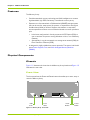
Memory Array - Rear View. . . . . . . . . . . . . . . . . . . . . . . . . . . . . . . . . . . . . . . . . . . . . . . . . . . . . . . . . . . . . . . . . 25
Front System Status LEDs. . . . . . . . . . . . . . . . . . . . . . . . . . . . . . . . . . . . . . . . . . . . . . . . . . . . . . . . . . . . . . . . . 26
Rear System LEDs . . . . . . . . . . . . . . . . . . . . . . . . . . . . . . . . . . . . . . . . . . . . . . . . . . . . . . . . . . . . . . . . . . . . . . . . 27
Power Supply. . . . . . . . . . . . . . . . . . . . . . . . . . . . . . . . . . . . . . . . . . . . . . . . . . . . . . . . . . . . . . . . . . . . . . . . . . . . . 27
Fan Module . . . . . . . . . . . . . . . . . . . . . . . . . . . . . . . . . . . . . . . . . . . . . . . . . . . . . . . . . . . . . . . . . . . . . . . . . . . . . . 28
VIMMs . . . . . . . . . . . . . . . . . . . . . . . . . . . . . . . . . . . . . . . . . . . . . . . . . . . . . . . . . . . . . . . . . . . . . . . . . . . . . . . . . . 34
VIMM Slot Locations — 42 Modules . . . . . . . . . . . . . . . . . . . . . . . . . . . . . . . . . . . . . . . . . . . . . . . . . . . . . . . . 36
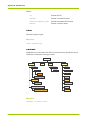
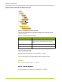
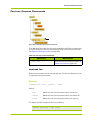
Memory Array Configuration Flowchart . . . . . . . . . . . . . . . . . . . . . . . . . . . . . . . . . . . . . . . . . . . . . . . . . . . . . . 40
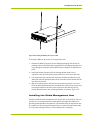
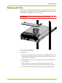
Installing the Memory Array into a Rack . . . . . . . . . . . . . . . . . . . . . . . . . . . . . . . . . . . . . . . . . . . . . . . . . . . . 43
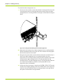
Installing the Cable Management Arm Mounting Bracket. . . . . . . . . . . . . . . . . . . . . . . . . . . . . . . . . . . . . . 44
Installing the Cable Holder . . . . . . . . . . . . . . . . . . . . . . . . . . . . . . . . . . . . . . . . . . . . . . . . . . . . . . . . . . . . . . . . . . 45
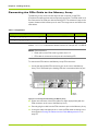
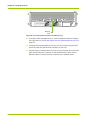
Connecting the PCIe Cable to the Memory Array . . . . . . . . . . . . . . . . . . . . . . . . . . . . . . . . . . . . . . . . . . . . 46
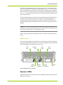
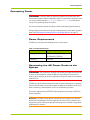
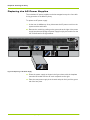
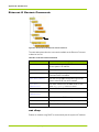
AC Power Receptacle Locations . . . . . . . . . . . . . . . . . . . . . . . . . . . . . . . . . . . . . . . . . . . . . . . . . . . . . . . . . . . 48
Connecting the Serial Cable to the Memory Array . . . . . . . . . . . . . . . . . . . . . . . . . . . . . . . . . . . . . . . . . . . 51
Connecting the Serial Cable to the Host Computer. . . . . . . . . . . . . . . . . . . . . . . . . . . . . . . . . . . . . . . . . . . . 51
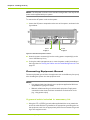
Connecting the Ethernet Cable to the Memory Array. . . . . . . . . . . . . . . . . . . . . . . . . . . . . . . . . . . . . . . . . 52
Connecting the PCIe Cable to the Host Computer. . . . . . . . . . . . . . . . . . . . . . . . . . . . . . . . . . . . . . . . . . . . . 53
Replacing a Fan Module . . . . . . . . . . . . . . . . . . . . . . . . . . . . . . . . . . . . . . . . . . . . . . . . . . . . . . . . . . . . . . . . . . 111
Replacing an AC Power Supply . . . . . . . . . . . . . . . . . . . . . . . . . . . . . . . . . . . . . . . . . . . . . . . . . . . . . . . . . . . . 112
Inserting the Replacement VIMM . . . . . . . . . . . . . . . . . . . . . . . . . . . . . . . . . . . . . . . . . . . . . . . . . . . . . . . . . 114
Direct-Attach Configuration (Linux) Flowchart . . . . . . . . . . . . . . . . . . . . . . . . . . . . . . . . . . . . . . . . . . . . . . 119
Australian C-Tick Label . . . . . . . . . . . . . . . . . . . . . . . . . . . . . . . . . . . . . . . . . . . . . . . . . . . . . . . . . . . . . . . . . . . 185
Front System Status LEDs. . . . . . . . . . . . . . . . . . . . . . . . . . . . . . . . . . . . . . . . . . . . . . . . . . . . . . . . . . . . . . . . 188
Context Levels. . . . . . . . . . . . . . . . . . . . . . . . . . . . . . . . . . . . . . . . . . . . . . . . . . . . . . . . . . . . . . . . . . . . . . . . . . . 214
Chassis Context Commands . . . . . . . . . . . . . . . . . . . . . . . . . . . . . . . . . . . . . . . . . . . . . . . . . . . . . . . . . . . . . . 221
Chassis>Board 0 Context Commands . . . . . . . . . . . . . . . . . . . . . . . . . . . . . . . . . . . . . . . . . . . . . . . . . . . . . 223
Chassis>Board 0>Slot Context Commands . . . . . . . . . . . . . . . . . . . . . . . . . . . . . . . . . . . . . . . . . . . . . . . . . 227
Chassis>Board0>Slot >VIMM Context Commands . . . . . . . . . . . . . . . . . . . . . . . . . . . . . . . . . . . . . . . . . . 230
Chassis>Board 0>VIMM-Summary Context Commands . . . . . . . . . . . . . . . . . . . . . . . . . . . . . . . . . . . . . 233
Chassis>Controller Context Commands. . . . . . . . . . . . . . . . . . . . . . . . . . . . . . . . . . . . . . . . . . . . . . . . . . . . 236
HP-AM456-9002A Rev 01
VMA-series Memory Array Installation and Service Guide
13
List of Figures
Figure D.8
Figure D.9
Figure D.10
Figure D.11
Figure D.12
Figure D.13
Figure D.14
Figure D.15
Figure D.16
Figure D.17
Figure D.18
Figure D.19
Figure D.20
Figure D.21
Figure D.22
Figure D.23
Figure D.24
Figure D.25
Figure D.26
14
Chassis>Controller>Ethernet Context Commands. . . . . . . . . . . . . . . . . . . . . . . . . . . . . . . . . . . . . . . . . . .
Chassis>Fan Tray Context Commands . . . . . . . . . . . . . . . . . . . . . . . . . . . . . . . . . . . . . . . . . . . . . . . . . . . . .
Chassis>Fan-Tray>Fan Context Commands. . . . . . . . . . . . . . . . . . . . . . . . . . . . . . . . . . . . . . . . . . . . . . . . .
CLI Context Level . . . . . . . . . . . . . . . . . . . . . . . . . . . . . . . . . . . . . . . . . . . . . . . . . . . . . . . . . . . . . . . . . . . . . . . .
RAID Context Level. . . . . . . . . . . . . . . . . . . . . . . . . . . . . . . . . . . . . . . . . . . . . . . . . . . . . . . . . . . . . . . . . . . . . . .
RAID>Group Context Level . . . . . . . . . . . . . . . . . . . . . . . . . . . . . . . . . . . . . . . . . . . . . . . . . . . . . . . . . . . . . . . .
RAID>Group>Maps Context Level. . . . . . . . . . . . . . . . . . . . . . . . . . . . . . . . . . . . . . . . . . . . . . . . . . . . . . . . . .
System Context Level . . . . . . . . . . . . . . . . . . . . . . . . . . . . . . . . . . . . . . . . . . . . . . . . . . . . . . . . . . . . . . . . . . . .
System>Alarms Context Level. . . . . . . . . . . . . . . . . . . . . . . . . . . . . . . . . . . . . . . . . . . . . . . . . . . . . . . . . . . . .
System>Boot-params Context Level . . . . . . . . . . . . . . . . . . . . . . . . . . . . . . . . . . . . . . . . . . . . . . . . . . . . . . .
System>LED-State Context Level . . . . . . . . . . . . . . . . . . . . . . . . . . . . . . . . . . . . . . . . . . . . . . . . . . . . . . . . . .
System>Logging Context Level . . . . . . . . . . . . . . . . . . . . . . . . . . . . . . . . . . . . . . . . . . . . . . . . . . . . . . . . . . . .
System>Logging>In-Memory Context Level . . . . . . . . . . . . . . . . . . . . . . . . . . . . . . . . . . . . . . . . . . . . . . . . .
System>Logging>In-Memory>Category Context Level . . . . . . . . . . . . . . . . . . . . . . . . . . . . . . . . . . . . . . . .
System>Logging>Syslog Context Level . . . . . . . . . . . . . . . . . . . . . . . . . . . . . . . . . . . . . . . . . . . . . . . . . . . . .
System>Status Context Level . . . . . . . . . . . . . . . . . . . . . . . . . . . . . . . . . . . . . . . . . . . . . . . . . . . . . . . . . . . . .
System>Sw-upgrade Level . . . . . . . . . . . . . . . . . . . . . . . . . . . . . . . . . . . . . . . . . . . . . . . . . . . . . . . . . . . . . . . .
System>Uptime Level . . . . . . . . . . . . . . . . . . . . . . . . . . . . . . . . . . . . . . . . . . . . . . . . . . . . . . . . . . . . . . . . . . . .
System>Version Level . . . . . . . . . . . . . . . . . . . . . . . . . . . . . . . . . . . . . . . . . . . . . . . . . . . . . . . . . . . . . . . . . . . .
VMA-series Memory Array Installation and Service Guide
238
243
244
245
251
253
255
257
273
275
277
279
281
285
287
290
294
297
298
HP-AM456-9002A Rev 01
List of Tables
Table 1.1
Table 1.2
Table 1.3
Table 1.4
Table 2.1
Table 2.2
Table 2.3
Table 3.1
Table 3.2
Table 3.3
Table 3.4
Table 3.5
Table 4.1
Table 4.2
Table 4.3
Table 5.1
Table 5.2
Table 5.3
Table 7.1
Table 8.1
Table 9.1
Table 9.2
Table A.1
Table D.1
Table D.2
Table D.3
Table D.4
Table D.5
Table D.6
Table D.7
Table D.8
Front LED Descriptions . . . . . . . . . . . . . . . . . . . . . . . . . . . . . . . . . . . . . . . . . . . . . . . . . . . . . . . . . . . . . . . . . . . 26
Rear LED Descriptions . . . . . . . . . . . . . . . . . . . . . . . . . . . . . . . . . . . . . . . . . . . . . . . . . . . . . . . . . . . . . . . . . . . 27
System Specifications . . . . . . . . . . . . . . . . . . . . . . . . . . . . . . . . . . . . . . . . . . . . . . . . . . . . . . . . . . . . . . . . . . . . 31
Direct-attached Host Computer Requirements . . . . . . . . . . . . . . . . . . . . . . . . . . . . . . . . . . . . . . . . . . . . . 31
Available VIMM Types . . . . . . . . . . . . . . . . . . . . . . . . . . . . . . . . . . . . . . . . . . . . . . . . . . . . . . . . . . . . . . . . . . . . 34
VIMM Configurations . . . . . . . . . . . . . . . . . . . . . . . . . . . . . . . . . . . . . . . . . . . . . . . . . . . . . . . . . . . . . . . . . . . . . 35
VIMM Slot Locations . . . . . . . . . . . . . . . . . . . . . . . . . . . . . . . . . . . . . . . . . . . . . . . . . . . . . . . . . . . . . . . . . . . . . 35
Required Installation Tools and Equipment. . . . . . . . . . . . . . . . . . . . . . . . . . . . . . . . . . . . . . . . . . . . . . . . . . 41
Image Names. . . . . . . . . . . . . . . . . . . . . . . . . . . . . . . . . . . . . . . . . . . . . . . . . . . . . . . . . . . . . . . . . . . . . . . . . . . . 46
Power Requirements . . . . . . . . . . . . . . . . . . . . . . . . . . . . . . . . . . . . . . . . . . . . . . . . . . . . . . . . . . . . . . . . . . . . . 47
Default Serial Port Settings . . . . . . . . . . . . . . . . . . . . . . . . . . . . . . . . . . . . . . . . . . . . . . . . . . . . . . . . . . . . . . . 50
DB-9 to DB-9 Serial Null Modem Cable Pinout . . . . . . . . . . . . . . . . . . . . . . . . . . . . . . . . . . . . . . . . . . . . . . 50
Memory Array System Default Settings . . . . . . . . . . . . . . . . . . . . . . . . . . . . . . . . . . . . . . . . . . . . . . . . . . . . 58
Changing the Default System Settings . . . . . . . . . . . . . . . . . . . . . . . . . . . . . . . . . . . . . . . . . . . . . . . . . . . . . 62
Syslog Definition Mappings. . . . . . . . . . . . . . . . . . . . . . . . . . . . . . . . . . . . . . . . . . . . . . . . . . . . . . . . . . . . . . . . 71
Displaying IP Information. . . . . . . . . . . . . . . . . . . . . . . . . . . . . . . . . . . . . . . . . . . . . . . . . . . . . . . . . . . . . . . . . . 87
Upgrade Image Names . . . . . . . . . . . . . . . . . . . . . . . . . . . . . . . . . . . . . . . . . . . . . . . . . . . . . . . . . . . . . . . . . . 100
Downloading Methods and Example Paths. . . . . . . . . . . . . . . . . . . . . . . . . . . . . . . . . . . . . . . . . . . . . . . . . 101
Memory Array Commands for Viewing Linux Driver Information . . . . . . . . . . . . . . . . . . . . . . . . . . . . . 127
Command Line Utilities for Displaying Windows Driver Information . . . . . . . . . . . . . . . . . . . . . . . . . . 144
vring Utility Parameters. . . . . . . . . . . . . . . . . . . . . . . . . . . . . . . . . . . . . . . . . . . . . . . . . . . . . . . . . . . . . . . . . . 160
perf_test Utility Options . . . . . . . . . . . . . . . . . . . . . . . . . . . . . . . . . . . . . . . . . . . . . . . . . . . . . . . . . . . . . . . . . . 164
Memory Array Models. . . . . . . . . . . . . . . . . . . . . . . . . . . . . . . . . . . . . . . . . . . . . . . . . . . . . . . . . . . . . . . . . . . 179
General Commands . . . . . . . . . . . . . . . . . . . . . . . . . . . . . . . . . . . . . . . . . . . . . . . . . . . . . . . . . . . . . . . . . . . . . 213
Chassis Context Commands . . . . . . . . . . . . . . . . . . . . . . . . . . . . . . . . . . . . . . . . . . . . . . . . . . . . . . . . . . . . . 221
Board 0 Context Commands . . . . . . . . . . . . . . . . . . . . . . . . . . . . . . . . . . . . . . . . . . . . . . . . . . . . . . . . . . . . . 223
Slot Context Commands . . . . . . . . . . . . . . . . . . . . . . . . . . . . . . . . . . . . . . . . . . . . . . . . . . . . . . . . . . . . . . . . . 227
VIMM Context Commands . . . . . . . . . . . . . . . . . . . . . . . . . . . . . . . . . . . . . . . . . . . . . . . . . . . . . . . . . . . . . . . 230
VIMM-summary Context Commands. . . . . . . . . . . . . . . . . . . . . . . . . . . . . . . . . . . . . . . . . . . . . . . . . . . . . . 233
show vim-summary Command Output Descriptions . . . . . . . . . . . . . . . . . . . . . . . . . . . . . . . . . . . . . . . . 234
Controller Context Commands . . . . . . . . . . . . . . . . . . . . . . . . . . . . . . . . . . . . . . . . . . . . . . . . . . . . . . . . . . . 236
HP-AM456-9002A Rev 01
VMA-series Memory Array Installation and Service Guide
15
List of Tables
Table D.9
Table D.10
Table D.11
Table D.12
Table D.13
Table D.14
Table D.15
Table D.16
Table D.17
Table D.18
Table D.19
Table D.20
Table D.21
Table D.22
Table D.23
Table D.24
Table D.25
Table D.26
Table D.27
Table D.28
Table D.29
16
Controller Context Commands . . . . . . . . . . . . . . . . . . . . . . . . . . . . . . . . . . . . . . . . . . . . . . . . . . . . . . . . . . .
Fan-tray Context Commands . . . . . . . . . . . . . . . . . . . . . . . . . . . . . . . . . . . . . . . . . . . . . . . . . . . . . . . . . . . . .
Fan Context Commands . . . . . . . . . . . . . . . . . . . . . . . . . . . . . . . . . . . . . . . . . . . . . . . . . . . . . . . . . . . . . . . . .
CLI Context Commands . . . . . . . . . . . . . . . . . . . . . . . . . . . . . . . . . . . . . . . . . . . . . . . . . . . . . . . . . . . . . . . . . .
Pagination Controls . . . . . . . . . . . . . . . . . . . . . . . . . . . . . . . . . . . . . . . . . . . . . . . . . . . . . . . . . . . . . . . . . . . . .
RAID Context Commands . . . . . . . . . . . . . . . . . . . . . . . . . . . . . . . . . . . . . . . . . . . . . . . . . . . . . . . . . . . . . . . .
RAID Group Context Commands. . . . . . . . . . . . . . . . . . . . . . . . . . . . . . . . . . . . . . . . . . . . . . . . . . . . . . . . . .
Maps Context Commands . . . . . . . . . . . . . . . . . . . . . . . . . . . . . . . . . . . . . . . . . . . . . . . . . . . . . . . . . . . . . . .
System Context Commands. . . . . . . . . . . . . . . . . . . . . . . . . . . . . . . . . . . . . . . . . . . . . . . . . . . . . . . . . . . . . .
Alarms Context Commands . . . . . . . . . . . . . . . . . . . . . . . . . . . . . . . . . . . . . . . . . . . . . . . . . . . . . . . . . . . . . .
Boot-params Context Commands. . . . . . . . . . . . . . . . . . . . . . . . . . . . . . . . . . . . . . . . . . . . . . . . . . . . . . . . .
LED State Context Commands . . . . . . . . . . . . . . . . . . . . . . . . . . . . . . . . . . . . . . . . . . . . . . . . . . . . . . . . . . .
Logging Context Commands . . . . . . . . . . . . . . . . . . . . . . . . . . . . . . . . . . . . . . . . . . . . . . . . . . . . . . . . . . . . .
In-memory Context Commands . . . . . . . . . . . . . . . . . . . . . . . . . . . . . . . . . . . . . . . . . . . . . . . . . . . . . . . . . . .
Message Categories . . . . . . . . . . . . . . . . . . . . . . . . . . . . . . . . . . . . . . . . . . . . . . . . . . . . . . . . . . . . . . . . . . . .
Category Context Commands . . . . . . . . . . . . . . . . . . . . . . . . . . . . . . . . . . . . . . . . . . . . . . . . . . . . . . . . . . . .
Syslog Context Commands . . . . . . . . . . . . . . . . . . . . . . . . . . . . . . . . . . . . . . . . . . . . . . . . . . . . . . . . . . . . . . .
Status Context Command. . . . . . . . . . . . . . . . . . . . . . . . . . . . . . . . . . . . . . . . . . . . . . . . . . . . . . . . . . . . . . . .
Sw-upgrade Context Commands. . . . . . . . . . . . . . . . . . . . . . . . . . . . . . . . . . . . . . . . . . . . . . . . . . . . . . . . . .
Uptime Context Command . . . . . . . . . . . . . . . . . . . . . . . . . . . . . . . . . . . . . . . . . . . . . . . . . . . . . . . . . . . . . . .
Version Context Command. . . . . . . . . . . . . . . . . . . . . . . . . . . . . . . . . . . . . . . . . . . . . . . . . . . . . . . . . . . . . . .
VMA-series Memory Array Installation and Service Guide
238
243
244
245
247
251
253
255
257
273
275
277
279
281
282
285
287
290
294
297
298
HP-AM456-9002A Rev 01
Preface
This document describes how to install and service the Memory Array.
•
Document Organization on page 17
•
Security on page 19
•
Document Conventions on page 18
•
Reference Documents on page 19
•
Contacting HP on page 19
Document Organization
This guide is organized into the following sections:
•
PART I: Product Overview
–
•
Chapter 1, VMA-series Overview—Introduces the Memory Array and its
features, components, and specifications.
– Chapter 2, Violin Intelligent Memory Modules—Describes the VIMM
technology including types, configurations, and slot locations.
PART II: Operation
–
•
HP-AM456-9002A Rev 01
Chapter 3, Installing the Array—Describes how to install the Memory
Array.
– Chapter 4, Configuring the Array—Describes how to perform the initial
configuration of the Memory Array.
– Chapter 5, Operating the System via the CLI—Describes the Memory
Array command line interface (CLI) and how to use it.
– Chapter 6, Servicing the Array—Describes how to safely service the
Memory Array including replacing fans, power supplies, and VIMMs.
PART III: Host Utilities
VMA-series Memory Array Installation and Service Guide
17
Preface
–
•
Chapter 7, Linux Drivers—Describes how to install, use, and remove the
Linux drivers on a host computer directly attached to the Memory
Array.
– Chapter 8, Windows Drivers—Describes how to install, use, and remove
the Windows drivers on a host computer directly attached to the
Memory Array.
– Chapter 9, Violin Utilities—Describes the Memory Array utility
commands and how to use them.
– Chapter 10, Performance Tuning and Troubleshooting—Describes how
to perform performance tuning and testing on the Memory Array.
Appendix A, Product Models—Lists the various Memory Array model
configurations.
•
Appendix B, Compliance Information—Contains compliance notices and
information for the Memory Array.
•
Appendix C, Alarm Reference—Describes the various system alarms that
may occur when using the Memory Array.
•
Appendix D, CLI Reference—Describes the commands available in the
Memory Array command line interface.
Document Conventions
Safety Icons
The table below summarizes warning, caution, and note icons used in this
document and includes sample text.
Safety Icons
Icon
18
Sample Text
Only authorized, qualified, and trained
personnel should attempt to work on this equipment.
WARNING!
WARNING!
Caution:
Caution:
Note:
Note: Read through this entire chapter and plan
your installation according to your location before
installing the equipment. The following procedures and
the order in which they appear are general installation
guidelines only.
Follow the listed safety precautions when
working on the Memory Array.
VMA-series Memory Array Installation and Service Guide
HP-AM456-9002A Rev 01
Security
Typographical Conventions
The table below summarizes the typographical conventions used in this guide.
Typographical Conventions
Format
Meaning
Bold
User Interface text.
Italic
Provides emphasis and identifies variables and
document titles.
Courier
Command names, examples, and output.
Courier bold
Input you must type exactly as shown.
<Courier italic>
Information for which you must supply a value.
[ ]
Optional command parameters are enclosed within
square brackets.
|
Separates a set of command choices from which only
one may be chosen.
{ }
Required command parameters that must be
specified are enclosed within curly brackets.
Security
HP cannot be responsible for unauthorized use of equipment and will not make
allowance or credit for unauthorized use or access.
Reference Documents
•
vSHARE Memory Gateway Installation and User's Guide
Contacting HP
For the name of the nearest HP authorized reseller:
See the Contact HP worldwide (in English) webpage (http://welcome.hp.com/
country/us/en/wwcontact.html).
For HP technical support:
•
In the United States, for contact options, see the Contact HP United States
webpage (http://welcome.hp.com/country/us/en/contact_us.html).
To contact HP by phone:
HP-AM456-9002A Rev 01
VMA-series Memory Array Installation and Service Guide
19
Preface
•
Call 1-800-HP-INVENT (1-800-474-6836). This service is available 24
hours a day, 7 days a week. For continuous quality improvement, calls may
be recorded or monitored.
•
If you have purchased a Care Pack (service upgrade), call 1-800-633-3600.
For more information about Care Packs, refer to the HP website (http://
www.hp.com/hps).
•
In other locations, see the Contact HP worldwide (in English) webpage
(http://welcome.hp.com/country/us/en/wwcontact.html).
For software drivers and firmware downloads:
1. Go to http://www.hp.com/support/downloads.
2. In the Search field on the right-hand side of the page, enter the exact
product name.
3. Select your product.
4. Select your operating system or Cross operating system (BIOS, Firmware,
Diagnostics, etc.). This takes you to the product download page.
5. Select the appropriate download, and follow the instructions.
20
VMA-series Memory Array Installation and Service Guide
HP-AM456-9002A Rev 01
PART I
Product Overview
Chapter 1
VMA-series Overview
Chapter 2
Violin Intelligent Memory Modules
CHAPTER 1
VMA-series Overview
This chapter introduces the VMA-series Memory Array, The VMA-series
Memory Array is the result of a partnership with Violin Memory, Inc. and is based
on the Violin 3000 Series Memory Array. HP and Violin have jointly tested and
certified the system with Linux, Windows, and HP-UX servers.
HP-AM456-9002A Rev 01
•
Features on page 24
•
Physical Components on page 24
•
Connectivity and Interfaces Overview on page 28
•
System Specifications on page 31
•
Direct-attached Host Computer Requirements on page 31
VMA-series Memory Array Installation and Service Guide
23
Chapter 1 - VMA-series Overview
Features
The Memory Array:
•
Combines standard memory technology and Violin intelligence to create a
high-bandwidth, high IOPS, low latency, cost-effective memory array.
•
Operates as a direct-attached or SAN-attached (vSHARE) storage system
that can be used for swap space, file systems, or exported as raw Logical
Unit Numbers (LUNs) or devices. Supports fast random or sequential
access operations as there are no mechanical heads to move or spindles to
spin.
•
•
In the base configuration it directly connects via PCI Express (PCIe) to
one or two host computers running Windows or Linux, or to a Memory
Gateway.
•
Alternatively, it may be connected to a storage area network (SAN) via
Fibre Channel or Ethernet (iSCSI).
Is designed for highly reliable data center operation. The system is built with
spare Power Supplies, Fans, and Violin Intelligent Memory Modules
(VIMMs).
Physical Components
Chassis
Figure 1.1 illustrates the front view of the Memory Array chassis and Figure 1.2
illustrates the rear view.
Front View
O
K
AC
USB
Ports
DC
O
K
ST
AT
U
S
AL
AR
M
The front panel has the Power and Reset buttons that allow you to start, stop, or
reset the Memory Array.
A
RAID
B
ADMIN
Front
LEDs
Reset
Button
Power
Button
Figure 1.1 Memory Array - Front View
24
VMA-series Memory Array Installation and Service Guide
HP-AM456-9002A Rev 01
Physical Components
The power button on the front of the array can be used to cause the array to
enter into a shutdown mode similar to executing the shutdown CLI command.
With a shutdown the media is taken offline and I/O stopped to the connected
hosts, but the array is left powered on and able to be managed via the CLI. Use
the reboot CLI command to bring the array media back online and allow I/O to
the connected hosts.
To shut down the system from the front panel, depress the power button for 4
seconds. If the LCD does not indicate the system is shutting down after 10
seconds, depress the power button for another 4 seconds. The LCD should
display that the system is shutdown and it is safe to remove the power cords if
desired.
The array is not actually powered off when using the power button.
Instead the array is logically shut down and the data paths are disabled, placing
the array in a safe mode for removing power cords.
Note:
Before turning off power to the Memory Array, shut down any direct-attached
hosts.
Rear View
The rear panel provides the interfaces for connecting input and output devices,
and power supplies. Each interface on the rear of the system has an associated
LED and indicates if the interface is in use or not.
PCIe
Port 1
Ethernet
Port
Rear
LEDs
AC
O
K
RAID
ADMIN
Serial
Console
DC
O
K
STA
TU
S
ALA
RM
A
B
Power
Supply A
PCIe
Port 2
LOC
Power
Supply B
GND
Figure 1.2 Memory Array - Rear View
System LEDs
Eight system LEDs are located on the front of the Memory Array and four system
LEDs are on the rear.
HP-AM456-9002A Rev 01
VMA-series Memory Array Installation and Service Guide
25
Chapter 1 - VMA-series Overview
Front LEDs
O
K
ST
AT
U
S
AL
AR
M
DC
AC
O
K
The front LEDs are illustrated in the figure below.
A
RAID
B
ADMIN
Figure 1.3 Front System Status LEDs
The front LEDs are described in the following table.
Table 1.1 Front LED Descriptions
System
A/B
RAID/ADMIN
LED Label
Color
When Lit
Description
AC OK
Indicates that the AC power feed to Power Supplies
A and B are connected correctly.
Green
DC OK
Indicates that the DC power feed from Power
Supplies A and B are operational.
Green
Status
Indicates the system status. When lit, the LED could Green
be:
• Flashing slowly—Indicates that the system monitor is
booting up.
• Flashing quickly—Indicates that the system software is
booting up, the VIMMs are being detected and
programmed, and no RAID groups have been created.
• Solid green—Indicates that the VIMMs are programmed,
RAID groups are created, and the system software has
completed booting.
Alarm
26
Indicates a system alarm when lit.
VMA-series Memory Array Installation and Service Guide
Red
HP-AM456-9002A Rev 01
Physical Components
Rear LEDs
The rear LEDs are illustrated in the figure below:
A
RAID
O
K
B
AC
LOC
C
Figure 1.4 Rear System LEDs
The Rear LEDs are described in the following table.
Table 1.2 Rear LED Descriptions
LED
Label
Status
Description
Indicates the system status. When lit, the LED could be:
Color When
Lit
Green
• Flashing slowly—Indicates that the system monitor is booting up.
• Flashing quickly—Indicates that the system software is booting up, the VIMMs
are being detected and programmed, and no RAID groups have been created.
• Solid green—Indicates that the VIMMs are programmed, that the RAID groups
are created, and that the system software has completed booting.
Alarm
Indicates a system alarm when lit.
When flashing, indicates that the datapath is either severely degraded or
is unavailable.
Red
Power A
Indicates that the first power feed is connected correctly.
Green
Power B
Indicates that the second power feed is connected correctly.
Green
Power Supplies
The chassis contains two power supplies that provide an AC power source for
the Memory Array. See System Specifications on page 31 for power supply
specifications.
Figure 1.5 Power Supply
HP-AM456-9002A Rev 01
VMA-series Memory Array Installation and Service Guide
27
Chapter 1 - VMA-series Overview
The power supplies convert the incoming AC power from individual AC feeds to
DC power used by the system. These 1200 W power supplies are redundant in
their configuration. The power supplies are hot-swappable at any time. See
Connecting the AC Power Cords to the System on page 47 for more information.
The power requirements for the Memory Array are based on the VIMM
configuration used.
•
84 VIMM configurations require over 800 W of power and require short
term access to 1200 W of power for functions such as formatting. This
level of power cannot be supplied through a single 110 V power supply. It is
required that each power supply be provided a circuit of over 200 V, with
7 A budgeted.
•
42 VIMM and below configurations require less than 700 W of power. A
circuit of over 200 V is recommended, but 110 V may be used.
Fans
Six fans are located in the front of the chassis and provide forced ventilation for
the Memory Array. The fans plug into connectors inside the front of the chassis.
See Replacing the Fans on page 111 for more information.
Figure 1.6 Fan Module
Connectivity and Interfaces Overview
The Memory Array contains two types of interfaces:
28
•
Management Interfaces which allow access to the command line interface
(CLI) for system configuration.
•
Storage Interfaces which allow connection to a host computer or Memory
Gateway for data transfer.
VMA-series Memory Array Installation and Service Guide
HP-AM456-9002A Rev 01
Connectivity and Interfaces Overview
Refer to Figure 1.2 for interface locations.
Management Interfaces
Access to the system command line interface (CLI) is available through the
following interfaces:
•
DB-9 Serial Debug Interface—Opens the CLI on the system.
•
Ethernet Interface—Opens the CLI on the system via Telnet or Secure Shell
(SSH).
See Connecting the Serial Cable on page 50 and Connecting the Ethernet Cable
on page 51 for information.
Storage Interfaces
A single Memory Array may be configured for:
•
Direct Attach via PCIe
•
SAN attach via Fibre Channel or iSCSI (vSHARE)
Note:
System configuration may be changed at any time.
The base platform supports a single PCIe x8 Gen1 (default) interface or dual
PCIe x4 Gen2 (option) interfaces that can directly connect to a host computer
(via a PCIe driver) or to a Memory Gateway. The optional memory gateways
provide specific network interfaces and functions such as SAN block storage or
NFS caching.
The VMA-series Memory Array does not currently support dual PCIe
connections.
Note:
PCIe Direct Attach
PCIe provides the lowest latency and highest bandwidth connectivity to the
Memory Array which supports eight lanes of PCIe Gen1 connectivity (20 Gbit/s
line rate). The PCIe connection can go to a single host (PCIe x8) for maximum
bandwidth or two hosts (PCIe x4 each) for reliability. See Connecting the PCIe
Cable to the Memory Array on page 46 for more information.
Where dual PCIe x4 interfaces are required, a special firmware image is loaded
onto the Memory Array. Similarly, the Memory Array can be changed back to a
single PCIe x8 interface through a new firmware load.
HP-AM456-9002A Rev 01
VMA-series Memory Array Installation and Service Guide
29
Chapter 1 - VMA-series Overview
Once a Memory Array is connected to a host computer it can be partitioned into
multiple volumes or virtual disks. Both Windows and Linux drivers are supplied
for the specific operating system used on the host.
For data transfers, there are two PCIe x8 interface ports on the rear of the
Memory Array. These interfaces support either single x8 or dual x4 PCIe
connections. The port configuration is determined by the firmware image loaded
on the system. See Upgrading the System Software on page 100 for more
information on changing the firmware image.
For maximum performance to a single host or single memory gateway, configure
the system data interface as a single PCIe x8 connection using Port 1 (see
Figure 1.2).
For high-availability connections to two hosts or two memory gateways, configure
the system data interface as dual PCIe x4 connections using Ports 1 and 2. This
dual configuration allows each host to read and write to the same address
space. When two hosts write to the same address, however, no guarantees are
made for the order in which the operations are performed; hosts must manage
potential conflicts via a clustered file system (e.g., GPFS) or some other
technique.
Fibre Channel and iSCSI SAN Attach (vSHARE)
vSHARE provides scale-out block storage (SAN) capability. Memory arrays
provide the flash memory storage and Memory Gateways provide the Fibre
Channel and/or iSCSI connectivity and LUN management. Clusters of gateways
and memory arrays can be built for extremely large-scale block storage systems.
Each Memory Array is managed as a container and multiple LUNs (volumes) are
configured on the array. Each LUN can be independently sized and masked for
use by different clients and clusters.
The same memory arrays and memory gateways can also be configured to use
Ethernet (10GbE). Individual servers may be connected via multiple 1 Gb/s or
10Gb/s links to remove performance bottlenecks and extract the most value
out of their processors and DRAM. vSHARE with iSCSI enables 10GbE
connectivity between performance servers and performance flash memory
arrays.
30
VMA-series Memory Array Installation and Service Guide
HP-AM456-9002A Rev 01
System Specifications
System Specifications
The table below lists the Memory Array system specifications.
Table 1.3 System Specifications
Specification
Electrical
Description
Input Power Voltage: 120 V or 240 V
Current Capacity: 12 A @ 120 V or 7 A @ 240 V
Environmental
Ambient Operating Temperature: 5 °C to 35 °C
Short Term: -5 °C to 40 °C
Operating Humidity: 5 to 85% (Non-Condensing)
Short Term: 5 to 90% (Non-Condensing)
Interfaces
x8 PCIe Interface (2)
Note: When both PCIe interfaces are used they become
x4.
Serial Interface via DB-9 male DTE port
10/100 Ethernet port
Logging
Syslog
Management
CLI: Serial, Telnet, SSH
Physical
Height: 5.19" (3U/132 mm)
Depth: 28.38" (721mm)
Width: 16.915" (430mm)
Minimum Rear Clearance: 7" (178mm)
Maximum Weight: 76 lbs (34.5 kg)
Direct-attached Host Computer Requirements
The table below lists the minimum requirements for a direct-attached host
computer used with the Memory Array.
Table 1.4 Direct-attached Host Computer Requirements
Minimum Requirements
Intel/AMD x86 or x86_64 computer
An available PCIe slot that communicates with the processor. Slots capable of
bidirectional x8 PCIe provide the best performance.
HP-AM456-9002A Rev 01
VMA-series Memory Array Installation and Service Guide
31
Chapter 1 - VMA-series Overview
Table 1.4 Direct-attached Host Computer Requirements
Minimum Requirements
Supported Operating Systems:
• Red Hat Enterprise Linux 5.6
• SUSE Linux Enterprise Server 11 SP1
• Windows Server 2008 R2
Serial communications application, such as vtkermit, tip, minicom, kermit,
hyperterm, teraterm, and PuTTY
See Connecting the PCIe Cable to a Host Computer or Memory Gateway on page
53 for more information.
32
VMA-series Memory Array Installation and Service Guide
HP-AM456-9002A Rev 01
CHAPTER 2
Violin Intelligent Memory Modules
This chapter describes the Violin Intelligent Memory Module (VIMM) technology,
types, configurations, and slot locations in the following sections:
HP-AM456-9002A Rev 01
•
Violin Intelligent Memory Modules (VIMMs) on page 34
•
VIMM Types on page 34
•
VIMM Configurations on page 35
•
VIMM Slot Locations on page 35
VMA-series Memory Array Installation and Service Guide
33
Chapter 2 - Violin Intelligent Memory Modules
Violin Intelligent Memory Modules (VIMMs)
A VIMM, illustrated in Figure 2.1:
•
Contains memory and interconnect diagnostics and error correction for
data reliability.
•
Offers data protection via a flash RAID (4+1Parity) function that provides
fault tolerance and low latency access to flash.
A fully populated system contains up to sixteen Parity VIMMs and four spare
VIMMs for failure protection. All memory modules are hot swappable with
automated rerouting that will not interrupt data service. In the case of a module
failure where the module must be replaced, the Memory Array does not have to
be powered down.
Figure 2.1 VIMMs
Insert VIMMs or VIMM blanks only, otherwise permanent
system damage will result.
WARNING!
VIMM Types
The Memory Array performance depends on the size of memory used and the
number of modules. VIMMs are available in the capacities listed in the following
table.
Table 2.1 Available VIMM Types
VIMM
Capacity
34
Raw Memory per Array
(84 VIMMs)
128 GB
10.8 TB
256 GB
21.5 TB
512 GB
43 TB
VMA-series Memory Array Installation and Service Guide
HP-AM456-9002A Rev 01
VIMM Configurations
Memory arrays store up to 64, 128, 256, or 512 GB of data per memory
module providing up to 43 TB of raw flash storage per system. The amount of
usable memory in a system is the number of VIMMs used for data storage,
which is four per redundant array of independent disks (RAID) group (up to 64
VIMMs), multiplied by the amount of memory per module, multiplied by the
usable percentage the system is formatted for. For example, in a fully loaded
system with 84 VIMMs, the usable memory is 64 VIMMs multiplied by 128 GB,
multiplied by the usable percentage, such as 87.5%, which is 7.2 TB.
VIMM Configurations
The Memory Array holds up to 84 VIMMs, which operate in the VIMM
configurations listed in the following table.
Table 2.2 VIMM Configurations
VIMMs
Active
Spare
84
80
4
42
40
2
VIMM Slot Locations
The Memory Array is available in several VIMM configurations. Table 2.3 lists the
VIMM slot numbers used for each configuration. Use the information in the table
when adding, removing, or replacing a non-working VIMM to ensure that the
VIMMs are still in their correct positions. See Replacing VIMMs on page 113 for
information on replacing an errored VIMM.
Table 2.3 VIMM Slot Locations
Number of
VIMMs
Slot Numbers
42
3, 4, 5, 6, 7, 8, 12, 13, 14, 15, 16, 17, 18, 22, 23, 24,
25, 26, 27, 35, 38, 39, 40, 41, 42, 43, 44, 45, 48, 60,
64, 65, 66, 67, 68, 69, 71*, 75*, 76, 78, 79, 80 (See
Figure 2.2)
84
All slots (0-83)
* Designates a filler slot.
Refer to the following section for a VIMM slot location diagram:
HP-AM456-9002A Rev 01
VMA-series Memory Array Installation and Service Guide
35
Chapter 2 - Violin Intelligent Memory Modules
42–Module Configuration
For this configuration VIMMs must be placed in the slot locations illustrated in
the following figure.
83
82
81
80
79
78
77
76
75
74
73
72
71
70
69
68
67
66
65
64
63
62
61
60
59
58
57
56
55
54
53
52
51
50
49
48
47
46
45
44
43
42
41
40
39
38
37
36
35
34
33
32
31
30
29
28
27
26
25
24
23
22
21
20
19
18
17
16
15
14
13
12
11
10
09
08
07
06
05
04
03
02
01
00
Fans
Fans
Fans
Figure 2.2 VIMM Slot Locations — 42 Modules
All remaining slots must contain blank filler VIMMs. The default spare VIMMs are
located at slots 71 and 75.
36
VMA-series Memory Array Installation and Service Guide
HP-AM456-9002A Rev 01
PART II
Operation
Chapter 3
Installing the Array
Chapter 4
Configuring the Array
Chapter 5
Operating the System via the CLI
Chapter 6
Servicing the Array
CHAPTER 3
Installing the Array
This chapter describes how to install the Memory Array in the following sections.
HP-AM456-9002A Rev 01
•
Installation and Configuration Overview on page 40
•
Rack-Mounting the Chassis on page 42
•
Connecting the PCIe Cable to the Memory Array on page 46
•
Connecting Power on page 47
•
Connecting Management Network on page 50
•
Connecting the PCIe Cable to a Host Computer or Memory Gateway on
page 53
•
Routing the Cables onto the Cable Management Arm on page 55
•
Powering up the Memory Array on page 56
VMA-series Memory Array Installation and Service Guide
39
Chapter 3 - Installing the Array
Installation and Configuration Overview
Memory Array installation and configuration occurs in five distinct phases:
•
Phase 1: Hardware Installation
•
Phase 2: Memory Array Configuration
•
Phase 3: Storage Configuration
•
Phase 4: Performance Testing and Tuning
•
Phase 5: Monitoring and Troubleshooting
PHASE 1:
Hardware Installation
1 Unpacking
Components
3 Connecting
2 Rack-Mounting
PHASE 2:
Memory Array
Configuration
4 Connecting
PCIe Cables
the Chassis
Power
5 Connecting
Management
Network
PHASE 4:
PHASE 3:
Direct-Attached
Configuration
Performance Tuning
and Testing
SAN Storage
Configuration
PHASE 5:
Monitoring and Troubleshooting
1 Monitoring
2 Troubleshooting
3 Contact
Customer Support
4 Servicing
the System
Figure 3.1 Memory Array Configuration Flowchart
The first phase in the flowchart is described in the current chapter. Phase 2,
memory array configuration, is described in Chapter 4, Configuring the Array.
Phase 3, direct-attach storage configuration, is described in Chapter 7, Linux
Drivers and Chapter 8, Windows Drivers for Linux and Windows respectively; for
SAN (vSHARE) configuration details refer to the vSHARE Memory Gateway
Installation and User's Guide. Phase 4, performance testing and tuning, is
described in Chapter 10, Performance Tuning and Troubleshooting and
40
VMA-series Memory Array Installation and Service Guide
HP-AM456-9002A Rev 01
Installation and Configuration Overview
Chapter 9, Violin Utilities. Phase 5, monitoring and troubleshooting is described
in Chapter 6, Servicing the Array and Chapter 9, Violin Utilities.
Required Installation Tools and Equipment
The table below lists the tools and equipment required during the installation
process.
Table 3.1 Required Installation Tools and Equipment
Item
#
HP-AM456-9002A Rev 01
Item Description
Quantity
1
Laptop for console access. DB-9 serial connector or
USB-to-DB-9 cable/dongle.
2
CAT 5 Ethernet Cable with RJ-45 Connectors, straight- 1 per array
through or cross-over, depending on your installation.
3
Flat Head Screw Driver, size 1/4"
1
4
Phillips Head Screw Drivers, size 2
1
VMA-series Memory Array Installation and Service Guide
1
41
Chapter 3 - Installing the Array
Rack-Mounting the Chassis
Installing the Memory Array in a 19"
Equipment Rack
The Memory Array fits into a standard 19" (482.6 mm) wide, four-post rack with
sliding rails as specified by EIA-310-D, IEC 60297, and DIN 41494 SC48D.
Square hole racks are supported.
Since there are a variety of 19" equipment racks available, the rack mounting
brackets can be configured in several ways to accommodate a range of frontrear post spacings–from 24" to 32". This adapts the slide rails to the various
equipment racks that may already exist at a customer’s site.
The Memory Array is extended via the slide rails to the front of the rack for live
servicing. A cable management arm is used to manage and extend the cables
for this process. To ensure there is sufficient room for the cable management
arm to easily fit within the rack, it is required that rack depths of 36" or greater
be used. Any doors on the rack must allow good front to back airflow.
Caution:
•
Improperly spaced mounting brackets and slide rails can cause the
Memory Array to fall out of the rack.
•
Because of the weight of the Memory Array, two people are required to
lift and place the system in an equipment rack.
•
If installed in a closed or multi-unit rack assembly, the operating ambient
temperature of the rack environment may be greater than the ambient
room temperature. Therefore, consider installing the equipment in an
environment compatible with the maximum ambient operating
temperature specified by the manufacturer.
•
Install the equipment in the rack so that the amount of air flow required
for safe operation of the equipment is not compromised.
•
Mount the equipment in the rack so that a hazardous condition is not
achieved due to uneven mechanical loading.
You must be able to access the rear of the Memory Array and the
equipment rack during installation.
Note:
The following procedure describes how to:
42
•
Install the sliding rails and mounting brackets onto the chassis if they have
not been installed prior to shipping.
•
Secure the chassis into the equipment rack. The rack mounting screws and
nuts are included in the shipping package.
VMA-series Memory Array Installation and Service Guide
HP-AM456-9002A Rev 01
Rack-Mounting the Chassis
Figure 3.2 Installing the Memory Array into a Rack
To install the Memory Array into a 19" equipment rack:
1.
Remove the Memory Array from the shipping packaging and remove all
packing materials. Visually inspect the system for any shipping damage and,
if any damage is detected, contact HP Customer Support for replacement
parts.
2.
Install the toolless mounting rails at the appropriate height in your
equipment rack. Orient the rails so they slide out to the front of the rack.
3.
Fully extend the rails until they lock into place. Position the Memory Array
above the rails and slide the buttons at the rear sides of the chassis into the
rear slots on the rails.
4.
Slip the remaining sets of buttons into the remaining cutouts in the rails.
Push the whole assembly back into the equipment rack and secure the rack
mounting brackets to the front of the equipment rack with the thumb
screws located on the front mounting brackets, as shown in Figure 3.2.
Installing the Cable Management Arm
Install the optional cable management arm at the rear of the chassis. The arm
consists of a mounting bracket and cable holder and keeps the cables from
becoming entangled when the system is fully extended from the equipment rack.
The cables are routed along the length of the arm and held in place with cable
ties. The cable management arm is not installed prior to shipping.
HP-AM456-9002A Rev 01
VMA-series Memory Array Installation and Service Guide
43
Chapter 3 - Installing the Array
To install the cable management arm:
1.
At the rear of the chassis, remove the shoulder screws and shims from the
rear equipment frame mounting bracket and set aside. Orient the cable
management arm mounting bracket on the right, as illustrated in the figure
below.
Figure 3.3 Installing the Cable Management Arm Mounting Bracket
44
2.
Align the thumb screws on the cable management arm mounting bracket
with the installation holes on the right rear of the chassis. Securely tighten
the thumb screws into the chassis.
3.
Using the four (4) shoulder screws and shims that were set aside in step 1,
secure the cable management arm mounting bracket to the rear
equipment frame mounting bracket, placing the shim between the shoulder
screws and the cable management arm mounting bracket, with the
enclosed Hex key. The cable management arm mounting bracket slides the
arm forward and enables the chassis to be fully extended from the
equipment rack for accessibility.
4.
At the rear side of the system, using the two (2) SEM 10-32 x 0.50 screws
included in the shipping package, secure the cable holder to the equipment
rack over the rear equipment frame mounting bracket on the right side of
the system as illustrated in the figure below.
VMA-series Memory Array Installation and Service Guide
HP-AM456-9002A Rev 01
Rack-Mounting the Chassis
Figure 3.4 Installing the Cable Holder
HP-AM456-9002A Rev 01
VMA-series Memory Array Installation and Service Guide
45
Chapter 3 - Installing the Array
Connecting the PCIe Cable to the Memory Array
The Memory Array communicates with the host computer via the PCIe
(Peripheral Component Interconnect Express) connection. The PCIe cable must
be connected to the PCIe port with the flashing LED. The software image on the
system dictates which interface port is used. The image names are listed in the
table below.
Table 3.2 Image Names
Image Name
PCIe Interface
Interface ID
v3000_Series_x8_p1_df-<release>.upg
PCIe x8 Interface for V3000
Port 1
v3000_Series_x4_p1p2_df-<release>.upg
Dual PCIe x4 Interfaces for V3000
Ports 1 and 2
Where <release> indicates the release number; for example, A3.7.2-18919.
•
Ensure that the:
Bend radius of the PCIe cable is greater than 1.9".
•
PCIe cable is connected to the port with the flashing LED.
Note:
To connect the PCIe cable to the Memory Array PCIe connector:
Locate the appropriate PCIe connector port at the rear of the Memory
Array. This is indicated by the flashing LED that is associated with the port.
RAID
ADMIN
AC
O
K
A
B
DC
O
K
STA
TU
S
ALA
RM
1.
LOC
PCIe
Port 1
PCIe
Port 2
Figure 3.5 Connecting the PCIe Cable to the Memory Array
46
2.
Orient one connector of the PCIe cable so it aligns appropriately with the
PCIe connector at the rear of the Memory Array.
3.
Securely plug the cable into the PCIe connector port on the Memory Array.
4.
If using the cable management arm, route the PCIe cable according to the
instructions in Routing the Cables onto the Cable Management Arm on
page 55.
VMA-series Memory Array Installation and Service Guide
HP-AM456-9002A Rev 01
Connecting Power
Connecting Power
Powering down the system processor interrupts traffic and
causes loss of system logs and diagnostic data. To preserve this diagnostic data
it is recommended that the vincident and/or save log commands be
used prior to powering down the system.
WARNING!
It is recommended to reboot the system rather than powering down then up.
Using a syslog server also ensures logs are stored prior to any reboot or power
down. See Displaying and Setting System Log (Syslog) Options on page 71.
Power Requirements
The Memory Array has the following power requirements:
Table 3.3 Power Requirements
Item
Requirement
Voltage Input Range
180 - 264VAC (1200 W)
90 - 264VAC (1000 W)
Frequency
47-63 Hz
Connecting the AC Power Cords to the
System
Only authorized, qualified, and trained personnel should attempt
to work on this equipment. Install the Memory Array with a 50 A maximum
branch circuit rating by an end-use application using a UL listed circuit breaker
rated at 50 A.
WARNING!
The Memory Array chassis has the AC power supplies installed prior to shipping.
Connect the AC power cord to either power receptacle on the Memory Array, or
both. Connecting a second power cord is for redundancy purposes.
The power supplies have an IEC-C20 male receptacle and accept an IEC-C19
female connector.
Caution: Consider the equipment connection to the supply circuit and the
effect that overloading the circuits might have on overcurrent protection and
supply wiring. Also consider the appropriate equipment nameplate ratings when
addressing this concern.
HP-AM456-9002A Rev 01
VMA-series Memory Array Installation and Service Guide
47
Chapter 3 - Installing the Array
The AC power cords are not a standard configuration. Use only the AC
power cords supplied with your system.
Note:
To connect the AC power cords to the system:
Locate the AC power receptacles at the rear of the system, as shown in the
figure below.
RAID
ADMIN
AC
O
K
A
B
DC
O
K
STA
TU
S
ALA
RM
1.
Power
Supply A
LOC
Power
Supply B
Figure 3.6 AC Power Receptacle Locations
2.
Insert the power connector(s) into the mating power receptacle(s) on the
rear of the Memory Array.
3.
If using the cable management arm, route the power cord(s) according to
the instructions in Routing the Cables onto the Cable Management Arm on
page 55.
Connecting Equipment Ground
Connect equipment ground from the equipment rack to the Memory Array only
after installing the system into the equipment rack.
Note:
•
Use appropriately sized wire for your equipment application. Minimum
acceptable wire gauge is 8 AWG.
•
Maintain reliable earthing of rack-mounted equipment. Supply extra
connections other than the direct connections to the branch circuit
(e.g., using power strips).
If ground cable included in accessory kit
1.
48
Using the 2.5 m (8.20 ft) ground cable supplied with the array, attach the
end of the cable with the lug installed to an appropriate grounding point on
the equipment rack. Use an appropriately sized screw to attach the ground
lug to the equipment rack.
VMA-series Memory Array Installation and Service Guide
HP-AM456-9002A Rev 01
Connecting Power
2.
Route the equipment ground cable to the rear of the equipment. Be sure to
leave an appropriate service loop to allow the removal of the equipment on
the slide rails. If using the cable management arm, route the equipment
ground wire around the arm. See Routing the Cables onto the Cable
Management Arm on page 55.
3.
Cut the length of the ground wire at the rear of the equipment as needed
for proper fit. If the length of the cable is cut, strip 13 mm (½ in) of
insulation from the cut end of the cable for installation into the grounding
lug.
4.
Attach the ground cable to the loose grounding lug provided with the
Memory Array. Tighten the screw on the lug to secure the cable to the lug.
5.
Using the grounding screw provided with the Memory Array, attach the lug
to the ground point on the rear of the equipment.
Attach the lug with the cable pointing up. Attaching the lug with the
cable pointing down may cause interference between the ground cable and
equipment mounted directly below the Memory Array which would prevent
the Memory Array from sliding out of the equipment rack for serviceability.
Note:
If ground cable not included in accessory kit
When installing a grounding cable, be sure to allow a sufficient service loop to
allow the array to be removed from the front of the rack for serviceability.
One end of the grounding cable should be attached to an appropriate ground
location on the equipment rack. The other end of the ground cable should be
attached to the grounding location on the rear of the Memory Array using a
¼-20 x ½" (max length) size screw.
HP-AM456-9002A Rev 01
VMA-series Memory Array Installation and Service Guide
49
Chapter 3 - Installing the Array
Connecting Management Network
Connecting the Serial Cable
The serial null modem cable connects the host computer to the system’s
debugging interface to retrieve system status and troubleshoot system events.
The default serial port settings are shown in the following table.
Table 3.4 Default Serial Port Settings
Setting
Value
Speed (baud rate)
9600
Parity
No
# of data bits/character
8
# of stop bits/character
1
Carrier Detect
No
Flow Control
xon/xoff
The serial cable’s pinout is described in the following table.
Table 3.5 DB-9 to DB-9 Serial Null Modem Cable Pinout
DB-9 Connector 1
DB-9 Connector 2
Female
Connector
Female
Connector
Receive Data
2
3
Transmit Data
Transmit Data
3
2
Receive Data
Data Terminal Ready
4
6+1
Data Set Ready +
Carrier Detect
System Ground
5
5
System Ground
Data Set Ready +
Carrier Detect
6+1
4
Data Terminal Ready
Request to Send
7
8
Clear to Send
Clear to Send
8
7
Request to Send
Description
Description
To connect the serial cable to the Memory Array and the host computer:
1.
50
Connect one DB-9 female connector on the serial cable to the male DB-9
connector on the rear of the Memory Array, see Figure 3.7. Secure the
cable to the chassis by tightening the screws on the DB-9 connector.
VMA-series Memory Array Installation and Service Guide
HP-AM456-9002A Rev 01
Connecting Management Network
AC
O
K
RAID
ADMIN
DC
O
K
STA
TU
S
ALA
RM
A
B
LOC
Serial
Console
Figure 3.7 Connecting the Serial Cable to the Memory Array
2.
If using the cable management arm, route the serial cable according to the
instructions in Routing the Cables onto the Cable Management Arm on
page 55.
3.
At the rear of the host computer, plug the other end of the serial cable into
the male DB-9 connector, see Figure 3.8. Secure the connection by
tightening the screws on the DB-9 connector.
Serial
Console
Figure 3.8 Connecting the Serial Cable to the Host Computer
Connecting the Ethernet Cable
The Ethernet cable connects the host computer to the system’s command line
interface (CLI) for configuration operations and retrieving system status.
For a direct host-to-system Ethernet connection, use a straight-through or crossover RJ-45 to RJ-45 CAT5 Ethernet cable. You can also use a straight-through
or cross-over cable to connect the Memory Array to a router, hub, or other
network device, provided that the host and the system can communicate with
each other.
To connect the Ethernet cable to the Memory Array and the host computer:
1.
HP-AM456-9002A Rev 01
Connect one RJ-45 connector on the Ethernet cable to the RJ-45
connector labeled ETHERNET on the rear of the Memory Array, as shown in
the figure below.
VMA-series Memory Array Installation and Service Guide
51
Chapter 3 - Installing the Array
AC
O
K
RAID
ADMIN
DC
O
K
STA
TU
S
ALA
RM
A
B
LOC
Ethernet
Port
Figure 3.9 Connecting the Ethernet Cable to the Memory Array
52
2.
If using the cable management arm, route the Ethernet cable according to
the instructions in Routing the Cables onto the Cable Management Arm on
page 55.
3.
If directly connecting the Memory Array to a host machine, plug the other
end of the cable into the Ethernet connector on the host.
4.
If connecting to a network device, such as a router, plug the other end of the
cable into the Ethernet connector on the network device. Use a second
Ethernet cable to connect the host computer to the network device.
VMA-series Memory Array Installation and Service Guide
HP-AM456-9002A Rev 01
Connecting the PCIe Cable to a Host Computer or Memory Gateway
Connecting the PCIe Cable to a Host Computer or Memory
Gateway
The Memory Array is connected via external PCIe cables (PCIe x8 cables) to one
or two host computer(s) or memory gateway(s). Hosts support applications,
such as databases, and run operating systems such as Linux or Windows.
Memory gateways provide network connectivity to SANs or LANs.
The Memory Array can be connected as a direct-attached storage system which
is either dedicated to a single host or shared between two hosts. Where the
Memory Array is shared across two hosts, the PCIe connections are logically
PCIe x4, but use PCIe x8 cables and interfaces.
A single host may connect to multiple memory arrays, enabling capacity and
performance to scale as needed. The host requires a PCIe Host Interface Board
(HIB) for each memory array that is to be connected.
Host Computer
The steps for connecting the Memory Array to a host computer are:
1.
Install the necessary PCIe HIB card into an available PCIe slot in the host
computer, ensuring that it is securely seated.
2.
Orient the unconnected end of the PCIe cable(s) to align with the PCIe
connector on the back of the host computer. The PCIe cable is keyed and
only goes in one way.
3.
Securely plug the cable(s) into the PCIe connector, as illustrated in the
figure below.
PCIe
Port
Figure 3.10 Connecting the PCIe Cable to the Host Computer
HP-AM456-9002A Rev 01
4.
Power-up the Memory Array (see Powering up the Memory Array on page
56). Ensure the RAID/ADMIN Status LED is solid green indicating the PCIe
ports have stabilized before continuing (approximately 1 minute).
5.
Power-up the host computer.
6.
If necessary, install the device drivers (see Chapter 7, Linux Drivers or
Chapter 8, Windows Drivers) and reboot the host.
7.
Verify the PCIe connection(s).
VMA-series Memory Array Installation and Service Guide
53
Chapter 3 - Installing the Array
Memory Gateway
The steps for connecting the Memory Array to a memory gateway are:
1.
Orient the unconnected end of the PCIe cable(s) to align with the PCIe
connector on the back of the Memory Gateway. The PCIe cable is keyed and
only goes in one way.
2.
Securely plug the cable(s) into the PCIe connector.
3.
Power-up the Memory Array (see Powering up the Memory Array on page
56). Ensure the RAID/ADMIN Status LED is solid green indicating the PCIe
ports have stabilized before continuing (approximately 1 minute).
4.
Power-up the Memory Gateway.
5.
Verify the PCIe connection(s).
Refer to the vSHARE Memory Gateway Installation and User's Guide for more
information.
54
VMA-series Memory Array Installation and Service Guide
HP-AM456-9002A Rev 01
Routing the Cables onto the Cable Management Arm
Routing the Cables onto the Cable Management Arm
After installing the Memory Array in an equipment rack and attaching the
necessary cables at the rear of the system, route the cables along the cable
management arm to prevent them from becoming entangled when the system
is fully extended from the equipment rack. Route the cables along the length of
the arm and hold in place with cable ties.
To route the cables along the cable management arm:
1.
Extend the cable management arm by removing the screws from the
equipment rack, holding the chassis brackets, and pulling out the Memory
Array from the equipment rack. Do not remove the system from the rack.
2.
At the rear of the chassis, route the installed ground wire, serial cable, and
power cables along the length of the cable management arm and secure
them with cable ties. Slip the cable ties around the slits in the arm and
secure the ties around the routed cables.
3.
Route the PCIe cable along the cable management arm and above the
hinge in the middle of the arm. Routing the PCIe cable above the hinge
ensures that when the system is in place in the equipment rack, the cable
radius stays above the minimum radius for PCIe cables.
Note:
4.
HP-AM456-9002A Rev 01
The minimum radius bend for a PCIe cable is 1.9".
Push the Memory Array back into the equipment rack and secure it to the
equipment frame using the screws that were removed earlier.
VMA-series Memory Array Installation and Service Guide
55
Chapter 3 - Installing the Array
Powering up the Memory Array
After connecting the AC power cords to the Memory Array, and connecting the
PCIe, Ethernet, and serial cables between the Memory Array and the host
computer or memory gateway, apply power to the Memory Array.
To complete the power up sequence:
1.
Plug each AC power cord from the chassis into an AC outlet.
2.
On the Memory Array, press the power button to start the system boot
process. The LEDs will begin to light up.
Note:
Some memory arrays do not have power buttons.
Power up the Memory Array before the host computer to ensure
PCIe communication because PCIe hotplug is not supported by some
current BIOS versions. An alternate method is to reboot the host computer
after powering up the Memory Array to ensure that the host computer
recognizes the system.
Note:
56
3.
During the boot up process, the green Status and the red Alarm LEDs will
flash. The Memory Array is fully booted when the Status LED is continuously
lit.
4.
Power up the host computer and log in as root on a Linux system, or as an
“administrator” on a Windows system to install the device driver. See
Chapter 7, Linux Drivers, or Chapter 8, Windows Drivers for details. Also,
see Chapter 5, Operating the System via the CLI for information on using
the command line interface (CLI).
VMA-series Memory Array Installation and Service Guide
HP-AM456-9002A Rev 01
CHAPTER 4
Configuring the Array
When the Memory Array is first powered on, all configuration settings are set to
default values. You must change the default settings to communicate with the
Memory Array over your network(s). This chapter explains how to log into the
Memory Array’s command line interface (CLI) to change system settings, such
as the hostname, IP address, DNS, and syslog options in the following sections.
HP-AM456-9002A Rev 01
•
Memory Array Default Settings on page 58
•
Connecting to the CLI on page 59
•
Changing the Default System Settings on page 62
•
Configuring DHCP Settings on page 65
•
Configuring Domain Name System (DNS) on page 67
•
Verifying the Ethernet Connection on page 70
•
Displaying and Setting System Log (Syslog) Options on page 71
•
Formatting the Memory Array on page 74
VMA-series Memory Array Installation and Service Guide
57
Chapter 4 - Configuring the Array
Memory Array Default Settings
The Memory Array has the system default settings listed in Table 4.1. Change
these settings using the CLI over a Telnet/SSH session or the serial port on the
Memory Array. See Changing the Default System Settings on page 62.
Table 4.1 Memory Array System Default Settings
Setting
58
Default Value
Host Name
violin
IP Address
192.168.1.2 (static)
IP Netmask
255.255.255.0
Gateway
undefined
DHCP
disabled
User Login Name
admin
User Password
admin
DNS Config
manual
DNS Name Server
undefined
DNS Search
undefined
Clock Source
host
Shell Connectivity
Serial, Telnet (port 23), SSH (port 22)
Serial Port Settings
9600 Baud, No Parity, 8 bits, 1 stop
System Log (syslog)
disabled
Message Logging Level
info
Command Line Editor
emacs
CLI Window Columns
80
Usable VIMM Capacity
65%
VMA-series Memory Array Installation and Service Guide
HP-AM456-9002A Rev 01
Connecting to the CLI
Connecting to the CLI
Logging into the CLI via the Serial Interface
Access the Command Line Interface (CLI) through the serial connection between
the host computer and the Memory Array. This connection was set up when the
equipment was installed into its permanent location. See Connecting the Serial
Cable on page 50.
See Table 3.4 on page 50 for the serial interface default values.
Your settings for the console connection may vary from the listed
default settings.
Note:
Use a USB-to-serial adapter to plug into the serial port on the back of
the Memory Array if your host computer does not have an available serial port.
Note:
Logging in via a Windows host computer
The following procedure shows how to connect to the Memory Array using a
terminal emulation application. For example, using PuTTY to connect to the CLI
through the serial connection:
1.
Log into the host computer as an administrator.
2.
From the Windows Start menu, select Programs > Accessories >
Communications > PuTTY.
The New Connection - PuTTY1 window opens.
3.
In the Connection Description window:
Type the name of the new connection in the Name field.
b. Select the appropriate icon from the list of available ones.
c. Click OK when done.
The Connect To window opens.
a.
4.
In the Connect using drop-down list, select Serial.
5.
Click Connect.
The following login prompt appears:
violin login:
6.
Type the default login name (admin) and password (admin) to log into the
system.
You are now connected to the CLI of the Memory Array and can access the
various CLI commands. Closing the PuTTY window terminates the
connection.
HP-AM456-9002A Rev 01
VMA-series Memory Array Installation and Service Guide
59
Chapter 4 - Configuring the Array
Logging in to the CLI via a Linux host computer
Connect to the Memory Array using the Kermit application or another terminal
application, such as tip, if your system does not have Kermit. Save the Kermit
parameter settings in a .kermrc file so that you do not need to type them each
time you connect. The Violin Utilities package for Linux includes Violin’s version of
Kermit called vtkermit.
Place the .kermrc file in your home directory so that the Kermit
application recognizes it; otherwise, use the -y option followed by the location
and file name of the configuration file.
Note:
To connect to the CLI through the serial connection:
1.
Log into the host computer as root.
2.
At the host computer’s command line prompt, type:
# kermit
or
# vtkermit
3.
Specify the line of the Kermit connection. At the Kermit prompt, type:
C-Kermit> set line /dev/ttyS0
The device name may vary depending on the host and the Linux
operating system that is running on the host.
Note:
4.
Specify the flow control mode. At the Kermit prompt, type:
C-Kermit> set flow xon/xoff
5.
Specify the speed of the Kermit connection. At the Kermit prompt, type:
C-Kermit> set speed 9600
6.
Since the serial interface of the Memory Array does not require the carrier
detect signal on the Kermit connection, at the Kermit prompt, type:
C-Kermit> set carrier-watch off
7.
To establish the connection to the Memory Array, at the Kermit prompt,
type:
C-Kermit> connect
The following login prompt appears:
violin login:
8.
60
Type the default login name (admin) and password (admin) to complete
logging into the system.
VMA-series Memory Array Installation and Service Guide
HP-AM456-9002A Rev 01
Connecting to the CLI
9.
At this point, you are connected to the CLI of the Memory Array and can
access the various CLI commands. To close the Kermit application, do one
of the following:
At the CLI prompt, type Ctrl-\, c, and then q.
b. Close the terminal window, which terminates the Kermit connection.
a.
HP-AM456-9002A Rev 01
VMA-series Memory Array Installation and Service Guide
61
Chapter 4 - Configuring the Array
Changing the Default System Settings
Table 4.1, Memory Array System Default Settings, on page 58 lists the system
configuration default values.
When you initially log into the Memory Array through the serial interface, change
the following default configuration parameters for security and ease of use.
Table 4.2 Changing the Default System Settings
Setting
Details
Hostname
See Changing the Hostname.
IP address,
Gateway address,
Netmask
Change the network address information to your
customer location scheme to prevent problems
connecting to the Memory Array. See Changing the
Default IP Address, Netmask, and Gateway on page
63.
Password
See Changing the Admin Password on page 62.
To reset back to the factory default settings, see Restoring the Factory Default
Settings on page 103.
Changing the Admin Password
Change the default password for the admin login at any time from the System
context level. The admin password must:
•
Have a length between 6-12 alphanumeric characters. If six characters are
used, then mix upper/lower case letters with numbers and/or punctuation.
•
Be a combination of upper and lower case letters and numbers.
•
Not be similar to a previous password.
•
Not be a palindrome.
If you specify an unacceptable password, you will get a message that the
password is too simple. By increasing the length of the password, you can use all
lower case or all upper case characters. In other words, the longer the
password, the less complicated it needs to be.
To change the admin password from the default value:
1.
Log into the Memory Array.
2.
Navigate to the System context level. At the root prompt, type:
context system
3.
At the System context prompt, type:
set admin password
62
VMA-series Memory Array Installation and Service Guide
HP-AM456-9002A Rev 01
Changing the Default System Settings
You will be prompted to enter a new password. If the new password meets
the requirements you will be prompted to enter the same password again.
A message appears indicating that the password has been changed.
The command displays information similar to the following if the new
password does not meet the requirements.
system> set admin password
Changing password for admin
Enter the new password (minimum of 6, maximum of 12 characters)
Please use a combination of upper and lower case letters and numbers.
Enter new password:
Bad password: too simple.
passwd: The password for admin is unchanged.
The password remains unchanged if the new one does not meet the
requirements.
You cannot reset the password back to the default password
(admin) for the admin user.
Note:
4.
To commit the changes made to the password, at the System context level
command prompt, type:
save config
Changing the Default IP Address, Netmask,
and Gateway
The Memory Array supports assigning IP addresses either statically or through
DHCP. The IP address, netmask, and gateway are initially set to default values,
see Table 4.1. Change these values to valid addresses within your network to
access the system CLI.
By default, DHCP is disabled. For convenience, the Ethernet port supports
automatic medium-dependent interface crossover (Auto-MDIX). With this, you
can connect the Ethernet port on the system to a computer's Ethernet port,
such as a laptop, for provisioning before connecting to a network switch.
You can switch between using DHCP and static addressing. When switching
from DHCP to static addressing, the Memory Array uses the default address
values if new values have not been pre-provisioned in the CLI. Alternatively, an IP
address can be assigned while DHCP is enabled and that IP address is used
automatically when switching from DHCP to static IP address assignment (i.e.,
DHCP is disabled).
It is recommended to manually configure the IP address of the Memory
Array to use a static IP address in the DHCP configuration file. If the IP address
is automatically assigned there is a risk of the system being assigned a different
IP address upon reboot.
Note:
HP-AM456-9002A Rev 01
VMA-series Memory Array Installation and Service Guide
63
Chapter 4 - Configuring the Array
When you change the IP address of the system, you will be logged off.
Log in again using the new IP address.
Note:
To change the system’s IP address, netmask, and gateway from the default
values:
1.
Log into the Memory Array.
Use Kermit or vtkermit, instead of Telnet, to change the IP address
in case the IP address is set incorrectly.
Note:
2.
Navigate to the Ethernet 0 context level. At the root prompt, type:
context chassis controller ethernet 0
3.
At the Ethernet 0 context prompt, type:
set ip-address <ip-address>[:<netmask>:<gateway>]
Where:
ip-address
Specifies the new system IP address.
netmask
Specifies the new system netmask.
gateway
Specifies the new system gateway address.
Changing the Hostname
To change the system’s hostname from the default value:
1.
Log into the Memory Array.
2.
Navigate to the system context level. At the root prompt, type:
context system
3.
At the system command prompt, type:
set name <hostname>
Where:
hostname
Specifies the new system hostname.
Note: Depending on your network, you may need to modify the DNS setting to
Telnet to the Memory Array via the hostname. Changing the hostname ensures
that you are connecting to the intended memory array if there are multiple
memory arrays on the network. See Configuring the DNS Name on page 67.
To access the system CLI, specify the new hostname instead of the IP address
in the Telnet session.
64
VMA-series Memory Array Installation and Service Guide
HP-AM456-9002A Rev 01
Configuring DHCP Settings
Configuring DHCP Settings
Configure several DHCP settings and DNS information automatically or manually
on the Memory Array.
Displaying DHCP Status
Display whether or not DHCP is being used to automatically set the system’s IP
address. By default DHCP is disabled.
1.
Log into the Memory Array.
2.
Navigate to the Ethernet 0 context level. At the root prompt, type:
context chassis controller ethernet 0
3.
At the Ethernet 0 context prompt, type:
show
When viewing DHCP status, information similar to the following displays:
chassis controller ethernet 0> show
dhcp
ip-address
netmask
gateway
mac-address
dns-config
dns-nameserver
dns-search
disabled
192.168.1.7
255.255.255.0
192.168.1.1
00:1B:97:00:00:05
manual
undefined
undefined
Enabling DHCP
Enable DHCP to automatically set the Memory Array’s IP address.
1.
Log into the Memory Array.
2.
Navigate to the Ethernet 0 context level. At the root prompt, type:
context chassis controller ethernet 0
3.
At the Ethernet 0 context prompt, type:
set dhcp enabled
4.
To commit the changes made to DHCP, at the System context level
command prompt, type:
save config
HP-AM456-9002A Rev 01
VMA-series Memory Array Installation and Service Guide
65
Chapter 4 - Configuring the Array
Disabling DHCP
Disable DHCP to manually set the Memory Array’s IP address. This is the system
default setting.
1.
Log into the Memory Array.
2.
Navigate to the Ethernet 0 context level. At the root prompt, type:
context chassis controller ethernet 0
3.
At the Ethernet 0 context prompt, type:
set dhcp disabled
4.
To commit the changes made to DHCP, at the System context level
command prompt, type:
save config
If DHCP is disabled, you must manually configure the system’s IP address. See
Changing the Default IP Address, Netmask, and Gateway on page 63.
Once you have manually configured the IP address while DHCP is disabled, you
will see that the manually provisioned IP addresses takes effect.
chassis controller ethernet 0> show
dhcp
ip-address
netmask
gateway
mac-address
dns-config
dns-nameserver
dns-search
66
disabled
10.10.0.125
255.255.255.0
10.10.0.1
00:1B:97:00:00:05
manual
undefined
undefined
VMA-series Memory Array Installation and Service Guide
HP-AM456-9002A Rev 01
Configuring Domain Name System (DNS)
Configuring Domain Name System (DNS)
There are two available methods for configuring DNS on the Memory Array:
1.
Automatic DNS configuration
2.
Manual DNS configuration
The Memory Array also allows pre-provisioning the DNS information to use when
you change your system from automatic DNS configuration to manual. If the
DNS configuration is currently in automatic mode, then the current
automatically provisioned DNS name and search information is considered to be
the provisioned settings used when the mode is set to manual.
By default, DNS configuration is performed automatically when Dynamic Host
Configuration Protocol (DHCP) is enabled and connected to a DHCP server that
supports specifying the DNS name. If DHCP is disabled, then the DNS mode is
automatically changed to manual.
Pre-provision the DNS configuration information before disabling DHCP.
Disabling DHCP forces the DNS mode to change to manual and use the default
values, making the system unreachable.
Note:
Configuring the DNS Name
When in automatic DNS mode and you set the IP address of the DNS name
server, you are pre-provisioning the value. It is not used until you change the DNS
mode to manual. You can configure the DNS name server’s IP address at any
time.
To specify the IP address of the DNS name server of the Memory Array:
1.
Log into the CLI via a serial connection or the Ethernet interface (see
Connecting to the CLI on page 59).
2.
Navigate to the Ethernet 0 context level. At the root prompt, type:
context chassis controller ethernet 0
3.
At the Ethernet 0 context prompt, type:
set dns-nameserver <ipaddr>
Where:
ipaddr
HP-AM456-9002A Rev 01
Specifies the IP address of the DNS server.
VMA-series Memory Array Installation and Service Guide
67
Chapter 4 - Configuring the Array
Configuring the DNS Search Domain Name
When in automatic DNS mode and you set the DNS search domain name, you
are pre-provisioning the value. It is not used until you change the DNS mode to
manual. You can configure the DNS search domain name at any time.
To specify the search domain name of the Memory Array:
1.
Log into the CLI via a serial connection or the Ethernet interface (see
Connecting to the CLI on page 59).
2.
Navigate to the Ethernet 0 context level. At the root prompt, type:
context chassis controller ethernet 0
3.
At the Ethernet 0 context prompt, type:
set dns-search <value>
Where:
value
Specifies the search domain name.
In the following example, the DNS name server IP address and the DNS search
domain values have been pre-provisioned.
chassis controller ethernet 0> show
dhcp
enabled
ip-address
10.10.0.126
netmask
255.255.255.0
gateway
10.10.0.1
mac-address
00:1B:97:00:00:06
dns-config
automatic
dns-nameserver
10.10.0.2
dns-search
violintech.net
prov-dns-nameserver 10.10.0.55
prov-dns-search
hi-octane-prod.net
Displaying the DNS Mode and Preprovisioned Information
To display the current DNS mode and various pre-provisioned DNS information
on the Memory Array:
1.
Log into the CLI via a serial connection or the Ethernet interface (see
Connecting to the CLI on page 59).
2.
Navigate to the Ethernet 0 context level. At the root prompt, type:
context chassis controller ethernet 0
68
VMA-series Memory Array Installation and Service Guide
HP-AM456-9002A Rev 01
Configuring Domain Name System (DNS)
3.
At the Ethernet 0 context prompt, type:
show
If DNS is currently in automatic mode, then the status for dns-config displays
automatic. In the following example, the DNS name server IP address and the
DNS search domain values have been pre-provisioned.
chassis controller ethernet 0> show
dhcp
enabled
ip-address
10.10.0.126
netmask
255.255.255.0
gateway
10.10.0.1
mac-address
00:1B:97:00:00:06
dns-config
automatic
dns-nameserver
10.10.0.2
dns-search
violintech.net
prov-dns-nameserver 10.10.0.55
prov-dns-search
violintech-prod.net
For information on clearing the provisioned DNS settings see Clearing
Provisioned DNS Information on page 89.
Setting the DNS Mode
To set the DNS mode on the Memory Array:
1.
Log into the CLI via a serial connection or the Ethernet interface (see
Connecting to the CLI on page 59).
2.
Navigate to the Ethernet 0 context level. At the root prompt, type:
context chassis controller ethernet 0
3.
At the Ethernet 0 context prompt, type:
set dns-config { manual | auto }
Where:
manual
Sets the DNS mode to manual.
auto
Sets the DNS mode to automatic.
You can pre-provision the IP address of the name server and the search domain
name while the DNS mode is set to automatic. See Configuring the DNS Name
on page 67 and Configuring the DNS Search Domain Name on page 68. Change
the DNS mode to manual to use the pre-provisioned values.
HP-AM456-9002A Rev 01
VMA-series Memory Array Installation and Service Guide
69
Chapter 4 - Configuring the Array
Verifying the Ethernet Connection
The Ethernet interface can also be used to connect to the CLI of the Memory
Array. This section explains how to verify that the Ethernet connection is
operating properly.
To verify the Ethernet connection:
1.
Log in to the host computer, as root on a Linux host or as an
administrator on a Windows host.
2.
To retrieve the IP address of the Memory Array, do one of the following:
a.
Log into the CLI via the serial port connection (see Logging into the CLI
via the Serial Interface on page 59) and type the following command at
the command prompt:
show chassis controller ethernet 0
This command returns the system’s IP address and other Ethernet
settings.
b.
3.
Connect to your DHCP server and retrieve the IP address it assigned to
your Memory Array.
Open a terminal or command line window and, at the command prompt,
type:
$ ping {<memory-array_ip_address> | <memory-array_name>}
Where:
memory-array_ip_address
The IP address assigned to the
Memory Array.
memory-array_name
The name of the Memory Array if
using DHCP and the memory array
is registered in the DNS.
If the host computer can connect to the Memory Array, then it will return a
successful ping message. If it cannot connect, then a failed ping message is
returned.
You can also connect to the system via the Ethernet port using Telnet or SSH as
described in Connecting to the CLI on page 76. If you are using DHCP and DNS,
you can use the system’s name instead of the IP address to connect through the
network.
70
VMA-series Memory Array Installation and Service Guide
HP-AM456-9002A Rev 01
Displaying and Setting System Log (Syslog) Options
Displaying and Setting System Log (Syslog) Options
The Memory Array logs system messages that can be sent to a host running a
syslog server for long term storage. If numerous messages are generated, then
the log buffer may fill up and, since it is a circular buffer, overwrite older
messages. The message level mapping between the message level definitions
and your host’s syslog message level definitions are listed in Table 4.3. View the
man page for syslog.conf on the host for more information.
Table 4.3 Syslog Definition Mappings
Memory Array
Syslog
DEBUG
debug
INFO
info
WARNING
warn
ERROR
emerg
FATAL
emerg
When syslog messages are received on the host, they are written to whatever
logging device is configured. Frequently, this means that warn messages are
written to a file, such as /var/log/messages or /var/adm/messages,
and emerg level messages are written to all root consoles. On the Memory
Array, messages that are set to the WARNING, ERROR, or FATAL level are sent
to the host.
Displaying the Configured IP Address of the
Syslog Host
To display the IP address of the syslog host to which the system log messages
will be sent:
1.
Log into the Memory Array.
2.
Navigate to the Syslog context level. At the root prompt, type:
context system logging syslog
3.
At the Syslog context prompt, type:
show host
The command displays information similar to the following:.
system logging syslog> show host
host
HP-AM456-9002A Rev 01
192.37.87.4
VMA-series Memory Array Installation and Service Guide
71
Chapter 4 - Configuring the Array
Setting the IP Address for the Syslog Host
Send system log messages to a host attached to the Memory Array via the
Ethernet port. This host must have syslog configured correctly. See your host’s
syslog documentation for instructions.
From the CLI prompt, use the ping command to verify the connection
between the Memory Array and the remote syslog host.
Note:
To set the IP address of the host to which the system log messages will be sent:
1.
Log into the Memory Array.
2.
Navigate to the Syslog context level. At the root prompt, type:
context system logging syslog
3.
At the Syslog context prompt, type:
set host <ip_address>
Where:
ip_address
4.
Specifies the IP address of the syslog host to which
the system log messages will be sent.
To commit the change made to the IP address, from the System context
level command prompt, type:
save config
Or, from the Syslog context level, type:
top
save config
Or
save system config
Determining the Status of the System Log
Service
Display the status of the service that sends the system log messages to a host.
1.
Log into the Memory Array.
2.
Navigate to the Syslog context level. At the root prompt, type:
context system logging syslog
3.
At the Syslog context prompt, type:
show service
72
VMA-series Memory Array Installation and Service Guide
HP-AM456-9002A Rev 01
Displaying and Setting System Log (Syslog) Options
The command displays information similar to the following:
system logging syslog> show service
service
on
Sending the System Log to a Host
Start or stop the service to send the system log messages to a host. By default,
it is off.
To set the status of the system log service:
1.
Log into the Memory Array.
2.
Navigate to the Syslog context level. At the root prompt, type:
context system logging syslog
3.
At the Syslog context prompt, type:
set service {on | off}
Where:
4.
on
Starts the service that sends the system log messages to the
syslog host.
off
Stops the service that sends the system log messages to the
syslog host.
To commit the change made, from the System context level command
prompt, type:
save config
Or, from the Syslog context level, type:
top
save config
Or:
save system config
HP-AM456-9002A Rev 01
VMA-series Memory Array Installation and Service Guide
73
Chapter 4 - Configuring the Array
Formatting the Memory Array
The array is formatted to 65% usable capacity at the factory and can
be used without change.
Note:
To change the format of the Memory Array:
1.
Log into the Memory Array.
2.
At the root CLI prompt, type:
format flash-capacity [<value>]
Where:
value
Specifies the percentage of usable flash capacity. Valid values
are:
•
•
•
•
•
•
50
65
78
84
87
90 — Not recommended for high performance or high reliability
systems.
Default is 65%.
Higher usable percentages provide more usable capacity where needed. Lower
usable percentages increase system write performance, endurance, and
reliability. For advice on selecting a good usable percentage, consult with HP
Customer Support.
74
VMA-series Memory Array Installation and Service Guide
HP-AM456-9002A Rev 01
CHAPTER 5
Operating the System via the CLI
The CLI resides on the Memory Array and is used to retrieve system status and
set configuration information. This chapter describes how to use the CLI to
perform various procedures in the following sections:
•
Connecting to the CLI on page 76
•
Displaying and Setting the CLI Window Options on page 79
•
Displaying and Setting System Information on page 83
•
Displaying and Setting Hardware Information on page 92
•
Displaying Alarms and Logs on page 96
•
Rebooting the Memory Array on page 98
•
Upgrading the System Software on page 100
See Appendix D, CLI Reference for details on using the CLI commands.
HP-AM456-9002A Rev 01
VMA-series Memory Array Installation and Service Guide
75
Chapter 5 - Operating the System via the CLI
Connecting to the CLI
Connect to the Memory Array’s CLI via SSH or Telnet on the host computer over
the Ethernet interface.
You can also log into the system via the serial port. See Logging into the CLI via
the Serial Interface on page 59 for instructions.
To connect to the Memory Array from a Windows machine, see Logging in via a
Windows host computer on page 59.
The default command line editor for the admin user is Emacs. You can
change the default editor to vi, see Setting the Command Line Editor on page 80.
Note:
Connecting via SSH
Connect to the CLI via SSH through your host computer.
On a Linux host, use your preferred command shell. On a Windows host, use a
GUI application, such as PuTTY, to SSH to the Memory Array.
The following is an example of what you will see after successfully connecting to
the CLI.
**************************************************************************
*
OAM-CLI
*
*
*
*
Operations, Administration & Maintenance - Command Line Interface
*
*
*
*
Copyright (c) 2006-2010, Violin Memory, Inc. All Rights Reserved.
*
*
*
*
S/W Build Info: Date 17:15:13
*
*
swbuild.violintech.net by user common
*
*
*
*
Release = Release 3.4
*
*
*
**************************************************************************
You are at the root node.
>
Connecting via Telnet
Connect to the CLI via a Telnet session on your host computer.
76
VMA-series Memory Array Installation and Service Guide
HP-AM456-9002A Rev 01
Connecting to the CLI
To connect to the Memory Array from a Windows machine, see Logging
in via a Windows host computer on page 59.
Note:
To connect to the Memory Array from a Linux desktop:
1.
Right-click on the desktop and select Open Terminal. At the command
prompt in the terminal window, type:
telnet <ip_address>
Where:
ip_address
HP-AM456-9002A Rev 01
Specifies the IP address of the Memory Array.
2.
At the login prompt, type the user login name (default is admin).
3.
At the password prompt, type the user password (default is admin).
4.
The following is an example of what you will see after successfully
connecting to the CLI.
VMA-series Memory Array Installation and Service Guide
77
Chapter 5 - Operating the System via the CLI
[root@lab5 ~]# telnet 10.10.20.4
Trying 10.10.20.4...
Connected to 10.10.20.4.
Escape character is '^]'.
violin login: admin
Password:
.....
.....
.....
.....
..... ~
.....
~
.....
~
.....
~
.....
~
.....
~ ~ ~
.....
~ ___ ___
.....
~ || // o
/ o
..
~
|| //
.--.
/
/_-_
~
||// / /
/ / / /
/
~
||/ / /___/ / / /
/
~ ___ ___
~
~
//| //|
~
//|| //||
.--. /_ _ .--. /.-- . .
// ||// || /__/ / / / /
/ /
/ /
// ||/ || /__ / / / /___/ /
/__/
/
http://www.violin-memory.com/
.__/
**************************************************************************
*
OAM-CLI
*
*
*
*
Operations, Administration & Maintenance - Command Line Interface
*
*
*
*
Copyright (c) 2006-2010, Violin Memory, Inc. All Rights Reserved.
*
*
*
*
S/W Build Info: Date 17:15:13
*
*
swbuild.violintech.net by user common
*
*
*
*
Release = R3.4
*
*
*
**************************************************************************
You are at the root node.
>
78
VMA-series Memory Array Installation and Service Guide
HP-AM456-9002A Rev 01
Displaying and Setting the CLI Window Options
Displaying and Setting the CLI Window Options
The settings for the terminal window displaying the current CLI session can be
modified to suit your display equipment. You can set or retrieve the following
window display options:
•
Number of columns and lines in the display window
•
Pagination
•
Command line editing mode
•
Size of the history buffer
Displaying the Number of Columns
To view the number of columns in the current CLI display window:
1.
Log into the Memory Array.
2.
Navigate to the CLI context level. At the root prompt, type:
context cli
3.
At the CLI context prompt, type:
show columns
The command displays information similar to the following:
cli> show columns
Current column setting is: 200
Setting the Number of Columns
Set the number of columns in the display window using the set columns
command. Set the number of columns in the range of 80-200 inclusively, with
the default setting of 80. This determines where the display lines are
automatically wrapped to the next line if you find that your terminal settings are
not wrapping lines correctly.
To set the number of columns in the display window:
1.
Log into the Memory Array.
2.
Navigate to the CLI context level. At the root prompt, type:
context cli
3.
At the CLI context prompt, type:
set columns {80-200}
HP-AM456-9002A Rev 01
VMA-series Memory Array Installation and Service Guide
79
Chapter 5 - Operating the System via the CLI
Displaying the Command Line Edit Mode
1.
Log into the Memory Array.
2.
Navigate to the CLI context level. At the root prompt, type:
context cli
3.
At the CLI context prompt, type:
show edit-mode
The command displays information similar to the following:.
cli> show edit-mode
Current edit-mode setting is: emacs
Setting the Command Line Editor
Set the command line editor to either Emacs or vi for the current CLI session.
The default editing mode is Emacs.
1.
Log into the Memory Array.
2.
Navigate to the CLI context level. At the root prompt, type:
context cli
3.
At the CLI context prompt, type:
set edit-mode {vi | emacs}
Where:
vi
Sets the command line editor for the current CLI session
to vi.
emacs
Sets the command line editor for the current CLI session
to Emacs. This is the default.
Displaying the History Buffer Size
1.
Log into the Memory Array.
2.
Navigate to the CLI context level. At the root prompt, type:
context cli
3.
At the CLI context prompt, type:
show history-size
80
VMA-series Memory Array Installation and Service Guide
HP-AM456-9002A Rev 01
Displaying and Setting the CLI Window Options
The command displays information similar to the following:
cli> show history-size
Current history-size setting is: 100
Setting the History Buffer Size
Modify the size of the history buffer to hold from 10-1000 lines.
To modify the number of lines in the history buffer:
1.
Log into the Memory Array.
2.
Navigate to the CLI context level. At the root prompt, type:
context cli
3.
At the CLI context prompt, type:
set history-size {10-1000}
Displaying the Number of Window Lines
This command is used by the paginator feature to scroll within large amounts of
displayed data, such as when the log is viewed.
1.
Log into the Memory Array.
2.
Navigate to the CLI context level. At the root prompt, type:
context cli
3.
At the CLI context prompt, type:
show lines
The command displays information similar to the following:
cli> show lines
Current row setting is: 24
Setting the Number of Window Lines
1.
Log into the Memory Array.
2.
Navigate to the CLI context level. At the root prompt, type:
context cli
3.
At the CLI context prompt, type:
set lines {10-100}
HP-AM456-9002A Rev 01
VMA-series Memory Array Installation and Service Guide
81
Chapter 5 - Operating the System via the CLI
Displaying the Pagination Mode
To view whether pagination is enabled or disabled in the current CLI window:
1.
Log into the Memory Array.
2.
Navigate to the CLI context level. At the root prompt, type:
context cli
3.
At the CLI context prompt, type:
show pagination
The command displays information similar to the following:.
cli> show pagination
Current pagination setting is: on
Setting the Pagination Mode
Enable or disable pagination in the CLI window. When pagination is disabled, data
displays on screen without pausing.
To enable or disable pagination in the CLI window:
1.
Log into the Memory Array.
2.
Navigate to the CLI context level. At the root prompt, type:
context cli
3.
At the CLI context prompt, type:
set pagination {on | off}
Where:
82
on
Enables pagination in the current CLI window.
off
Disables pagination in the current CLI window.
VMA-series Memory Array Installation and Service Guide
HP-AM456-9002A Rev 01
Displaying and Setting System Information
Displaying and Setting System Information
You can display and set various system information such as the system date and
time, system operational time, the system’s IP address, the log, spare VIMM
information, and RAID group mapping. The following sections describe how to
display and set this information.
Displaying System Status Information
Display the status of the various software modules and the validity of the current
VIMM configuration.
1.
Log into the Memory Array.
2.
Navigate to the System context level. At the root prompt, type:
context system
3.
At the System context prompt, type:
show status
By default, the display paginates. The example below shows representative text
that may be displayed. Actual text that is displayed is determined by your
system’s configuration.
system> show status
alarm-mgr
data-mgr
diagnostics-mgr
hardware-mgr
inventory-mgr
raid-mgr
vimm-mon
data-plane
raid-rebuild
vimm-config
failed-vimm-ids
admin-down-vimm-ids
missing-vimm-ids
host-interfaces
slot
state
protocol
link-width
neg-link-width
max-data-rate
cfg-data-rate
host
HP-AM456-9002A Rev 01
running
running
running
running
running
running
running
available
active (group 2, vimm 07, 47% complete)
out-of-spec-42-vimm
32, 61
60
15
port-1
enabled
pcie
4
4
10 Gb/s
10 Gb/s
detected
VMA-series Memory Array Installation and Service Guide
83
Chapter 5 - Operating the System via the CLI
slot
state
protocol
link-width
neg-link-width
max-data-rate
cfg-data-rate
host
slot
state
host
port-2
enabled
pcie
4
4
10 Gb/s
10 Gb/s
detected
port-0
disabled
undetected
If the VIMM configuration is invalid, or the system is rebuilding the RAID groups,
then up to two extra lines are displayed that list:
•
ID numbers of the affected VIMMs
•
When the RAID group rebuild is active
•
Affected RAID group and VIMM
Displaying the System Operational Time
Display how long a system has been operational since the last time it was
rebooted (i.e., uptime). The time is displayed in tenths of a second and in year, day,
HH:MM:SS format.
To display how long the system has been operational:
1.
Log into the Memory Array.
2.
Navigate to the System context level. At the root prompt, type:
context system
3.
At the System context prompt, type:
show uptime
The command displays information similar to the following:.
system> show uptime
tenths-second
time
132712724
0 years, 153 days, 14:27:52
Where:
tenths-second
84
Displays how long, in tenths of a second, the system
has been operational since the last power cycle or
system reboot.
VMA-series Memory Array Installation and Service Guide
HP-AM456-9002A Rev 01
Displaying and Setting System Information
Displays how long the system has been operational
since the last power cycle or system reboot in year,
day, hour formats.
time
Displaying the System Date and Time
1.
Log into the Memory Array.
2.
Navigate to the System context level. At the root prompt, type:
context system
3.
At the System context prompt, type:
show clock
The command displays information similar to the following:.
system> show clock
clock 2009-07-04T15:39:27
Where:
clock
Displays the date and time in the format yyyy-mmddThh:mm:ss.
The T is a delineator between the date and the time.
Setting the System Date and Time
1.
Log into the Memory Array.
2.
Navigate to the System context level. At the root prompt, type:
context system
3.
At the System context prompt, type:
set clock <yyyy-mm-dd>T<hh:mm:ss>
Where:
yyyy-mm-dd
Sets the date in the format:
• yyyy - The 4-digit year.
• mm - The 2-digit month. Valid values are 01 to 12.
• dd - The 2-digit day. Valid values are 01 to 31.
T
The delineator between the date and the time.
hh:mm:ss
Sets the time in the format:
• hh - The 2 digit hour. Valid values are 00 to 23.
• mm - The 2-digit minutes. Valid values are 00 to 59.
• ss - The 2-digit seconds. Valid values are 00 to 59.
HP-AM456-9002A Rev 01
VMA-series Memory Array Installation and Service Guide
85
Chapter 5 - Operating the System via the CLI
Displaying the System Clock Source
The clock source can be the host computer or the Memory Array.
1.
Log into the Memory Array.
2.
Navigate to the System context level. At the root prompt, type:
context system
3.
At the System context prompt, type:
show clock-source
The command displays information similar to the following:.
system> show clock-source
clock-source
host
Setting the System Clock Source
The clock source can be set to the host computer or the Memory Array. The
clock on the system only keeps a running count of the number of seconds that
the system has been operational. It does not keep an accurate calendar date and
time. If the system is rebooted, then the elapsed time is not accounted for when
the system finishes the reboot process and is again operational.
1.
Log into the Memory Array.
2.
Navigate to the System context level. At the root prompt, type:
context system
3.
At the System context prompt, type:
set clock-source { host | local }
Where:
host
Sets the clock source to the host computer. This is the
default value.
local
Sets the clock source to the Memory Array.
Displaying the Software Version
1.
Log into the Memory Array.
2.
Navigate to the Version context level. At the root prompt, type:
context system version
3.
At the System context prompt, type:
show
86
VMA-series Memory Array Installation and Service Guide
HP-AM456-9002A Rev 01
Displaying and Setting System Information
The command displays information similar to the following:
system version> show
software version:
software build date:
software build info:
<release>
<date> 12:44:52
built on swbuild.violintech.net by user common
CPL bootloader version:
OAM bootloader version:
CPL OS version:
OAM OS version:
CPL factory image version:
OAM factory image version:
upgrade image version:
<release>
<release>
<release>
<release>
<release>
<release>
(<release>_x8ans @ <date> 14:55
controller version info:
saxpow version info:
saxled version info:
15749_x8a @ <date> 11:39
8418 @ 03/12/08 15:26
7642 @ 01/25/08 13:48
Displaying the System IP Information
The following table lists the IP information that can be displayed.
Table 5.1 Displaying IP Information
Label
Description
dhcp
enabled
ip-address
10.10.0.126
netmask
255.255.255.0
gateway
10.10.0.1
mac-address
00:1B:97:00:00:05
dns-config
automatic
dns-nameserver
10.10.0.2
dns-search
domain.net
provisioned-info
See the following lines:
prov-ip-address
192.168.1.2
prov-netmask
255.255.255.0
prov-gateway
192.168.2.45
To display the IP address information:
1.
HP-AM456-9002A Rev 01
Log into the CLI via a serial connection or the Ethernet interface (see
Connecting to the CLI on page 76).
VMA-series Memory Array Installation and Service Guide
87
Chapter 5 - Operating the System via the CLI
2.
Navigate to the Ethernet 0 context level. At the root prompt, type:
context chassis controller ethernet 0
3.
At the Ethernet 0 context prompt, type:
show
The command displays text similar to the following:
chassis controller ethernet 0> show
dhcp
ip-address
netmask
gateway
mac-address
dns-config
dns-nameserver
dns-search
provisioned-info
prov-ip-address
prov-netmask
enabled
10.10.0.126
255.255.255.0
10.10.0.1
00:1B:97:00:00:05
automatic
10.10.0.2
domain.net
192.168.1.2
255.255.255.0
This example indicates that DHCP is currently enabled and that the IP address
is currently 10.10.0.126. However, if you were to change the network
configuration to static, the IP address used would be 192.168.1.2.
Displaying the System’s Hostname
1.
Log into the Memory Array.
2.
Navigate to the System context level. At the root prompt, type:
context system
3.
At the System context prompt, type:
show name
The command displays information similar to the following:.
system name> show
name
Violin Memory Array
Retrieving the MAC Address
The MAC address of the Memory Array’s Ethernet port can be found on the back
of the system or in the system attribute files.
To retrieve the device MAC address and serial number, do one of the following:
88
VMA-series Memory Array Installation and Service Guide
HP-AM456-9002A Rev 01
Displaying and Setting System Information
1.
From the CLI prompt, type:
show chassis controller ethernet 0
2.
Log into the host computer and type:
vinfo
To add the Memory Array’s MAC address to your DHCP server, consult your
DHCP server documentation.
Clearing Provisioned IP Information
Provisioned IP address information can be cleared at any time.
1.
Log into the CLI via a serial connection or the Ethernet interface (see
Connecting to the CLI on page 76).
2.
Navigate to the Ethernet 0 context level. At the root prompt, type:
context chassis controller ethernet 0
3.
At the Ethernet 0 context prompt, type:
clear ip-address
The command displays information similar to the following:
chassis controller ethernet 0> clear ip-address
chassis controller ethernet 0> show
dhcp
ip-address
netmask
gateway
mac-address
dns-config
dns-nameserver
dns-search
enabled
10.10.0.126
255.255.255.0
10.10.0.1
00:1B:97:00:00:06
automatic
10.10.0.2
violintech.net
Clearing Provisioned DNS Information
Clear provisioned DNS name server and DNS search domain information.
1.
Log into the CLI via a serial connection or the Ethernet interface (see
Connecting to the CLI on page 76).
2.
Navigate to the Ethernet 0 context level. At the root prompt, type:
context chassis controller ethernet 0
HP-AM456-9002A Rev 01
VMA-series Memory Array Installation and Service Guide
89
Chapter 5 - Operating the System via the CLI
3.
At the Ethernet 0 context prompt, type:
clear dns-nameserver
clear dns-search
4.
To commit the changes made, at the System context level command
prompt, type:
save config
Displaying the VIMM RAID Group Mapping
The Memory Array supports up to 16 RAID groups per system. Each RAID group
can contain up to five VIMMs and supports data striping across the VIMMs and
RAID groups. Four VIMMs in a RAID group contain data and one contains parity
information. Each RAID group can tolerate a single VIMM failure with no loss of
data.
To display the mapping of the RAID groups across the VIMMs:
1.
Log into the Memory Array.
2.
Navigate to the RAID Group context level. At the root prompt, type:
context raid group <n>
Where:
n
3.
Specifies the RAID group number.
At the RAID Group context prompt, type:
show maps
The command displays information similar to the following:
raid group 2> show maps
group-number
id
state
2
76,13,44,67,69
data,data,data,data,data
Where:
90
groupnumber
Indicates the RAID group ID.
id
Indicates the physical VIMM ID, and matches the slot
number on the main board.
VMA-series Memory Array Installation and Service Guide
HP-AM456-9002A Rev 01
Displaying and Setting System Information
state
Indicates the state of the VIMM in the 5-VIMM RAID
group. Valid values are:
• data—VIMM is being used for data, either user data or parity
data.
• REBUILDING—VIMM is currently being rebuilt by the RAID
engine to recover from a prior failure.
• FAULT—A fault has occurred for this VIMM. If a spare is
available, a rebuild occurs for this virtual VIMM.
Displaying the Spare VIMM Information
Using the CLI, display the ID numbers of the VIMMs that are designated as
spares for use with the RAID groups.
1.
Log into the Memory Array.
2.
Navigate to the RAID context level. At the root prompt, type:
context raid
3.
At the RAID context prompt, type:
show spare-ids
The command displays information similar to the following:
raid> show spare-ids
spare-ids
HP-AM456-9002A Rev 01
30,31,32,52
VMA-series Memory Array Installation and Service Guide
91
Chapter 5 - Operating the System via the CLI
Displaying and Setting Hardware Information
Display hardware information for the Memory Array, including:
•
Fan tray status
•
Which slots are populated with VIMMs
•
Individual VIMM information
•
Test slots
•
System LEDs
Displaying VIMM Configuration Information
Display the VIMM configuration information at the Slot context level.
To display the VIMM configuration information:
1.
Log into the Memory Array.
2.
Navigate to the desired Slot context level. At the root prompt, type:
context chassis board 0 slot <n>
Where:
n
3.
Specifies the VIMM slot number to move to. Valid values are in
the range of 0–83, inclusive.
At the context prompt, type:
show vimm
This command displays text similar to the following:
chassis board 0 slot 56> show vimm
admin-state
oper-state
vimm-state
raid-group
vimm-type
mem-type
raw-capacity
raw-capacity-bytes
fmt-capacity
fmt-capacity-bytes
part-number
serial-number
mfg-date
fw-date
fw-version
92
up
up
active
0
FLASH
SLC-NAND
68.7GB (64GiB)
68,719,476,736
45.1GB (42GiB)
45,097,156,608
1000159A-B-P4
18094R00000003
20090422
Thu Feb 11 17:54:00 2010
0x39df
VMA-series Memory Array Installation and Service Guide
HP-AM456-9002A Rev 01
Displaying and Setting Hardware Information
sw-date
sw-version
is-programmed
id-assigned
environment
temperature
sensor-1.2v
sensor-1.8v
sensor-2.5v
sensor-3.3v
run-time-stats
run-time
stats-date
format-date
user-reads
user-read-bytes
user-writes
user-write-bytes
ecc-cor-counts
one-bit
two-bits
three-bits
four-plus-bits
total-cor
ecc-corrected
raid-corrected
blk-boot-fails
blk-erase-fails
blk-prog-fails
blk-ecc-thresh
blk-ecc-uncor
erase-counts
blk-erase-target
blk-erase-avg
flash-health
failed-blocks
failed-die
perform-thresh
rebuild-thresh
critical-thresh
Fri Feb 12 00:07:00 2010
0x39dd
true
true
66C (OK)
1.14
1.79
2.42
3.35
0 years, 0 days 15:22:04
Wed Feb 17 10:37:39 2010
Tue Feb 16 19:41:08 2010
130,233,145
133,358,740,480
130,233,037
133,358,629,888
3
0
0
0
3
3
0
0
0
0
0
0
(rate: 2.30e-08)
(rate: 0.00e+00)
100,000
18.20
342
0
0.95%
0.64%
0.48%
(0.13%)
(0.00%)
(OK)
(OK)
(OK)
Displaying the Number of VIMMs
Display the number of VIMMs in the system, the corresponding slot ID number,
and the VIMM type.
To display a summary of VIMMs currently installed:
1.
Log into the Memory Array.
2.
Navigate to the Board 0 context level. At the root prompt, type:
context chassis board 0
HP-AM456-9002A Rev 01
VMA-series Memory Array Installation and Service Guide
93
Chapter 5 - Operating the System via the CLI
3.
At the context prompt, type:
show vimm-summary
The command displays information similar to the following:
chassis board 0> show vimm-summary
num-vimms
installed-vimm-ids
flash-vimm-ids
admin-down-vimm-ids
installed-mem-raw
usable-mem-raw
parity-mem-raw
spare-mem-raw
unavailable-mem-raw
formatted-percentage
usable-mem-formatted
42
3-8,12-18,22-27,35,38-45,48,60,64-69,71,75,76,78-80
3-8,12-18,22-27,35,38-45,48,60,64-69,71,75,76,78-80
39
2886.2GB (2688GiB)
2199.0GB (2048GiB)
549.8GB ( 512GiB)
68.7GB ( 64GiB)
68.7GB ( 64GiB)
78.1%
1718.0GB (1600GiB)
Displaying Fan Status
Display the status of the system fans for maintenance and troubleshooting
purposes. The fans are located in two fan trays designated as 1 (top) and 2
(bottom), and the fans are designated as Left, Center, and Right.
To display the current status of the fans:
1.
Log into the Memory Array
2.
Navigate to the desired Fan context level. At the root prompt, type:
context chassis fan-tray {1 | 2}
Where:
3.
1
Specifies the top fan tray.
2
Specifies the bottom fan tray.
At the context prompt, type:
show fan {left | center | right}
Where:
94
left
Specifies the left fan in the specified fan tray.
center
Specifies the center fan in the specified fan tray.
right
Specifies the right fan in the specified fan tray.
VMA-series Memory Array Installation and Service Guide
HP-AM456-9002A Rev 01
Displaying and Setting Hardware Information
The command displays information similar to the following:.
chassis fan-tray 1> show fan left
speed
rpm
high
4800
Displaying Main Board Information
1.
Log into the Memory Array.
2.
Navigate to the Board 0 context level. At the root prompt, type:
context chassis board 0
3.
At the context prompt, type:
show info
The command displays information similar to the following:.
chassis board 0> show info
part-number 1000074S-C-08
version
serial-number
mfg-date
environment
ambient-temp
controller-temp
sensor-12v-a
sensor-12v-b
HP-AM456-9002A Rev 01
0
16095R00000237
20090723
36C (OK)
57C (OK)
11.80
11.83
VMA-series Memory Array Installation and Service Guide
95
Chapter 5 - Operating the System via the CLI
Displaying Alarms and Logs
Display the current alarms that light the System LED on the Memory Array to
help prevent system damage in the case of a fan failure, lid removal, or to
diagnose performance problems when one or more VIMMs are affected by high
temperatures.
See Appendix C, Alarm Reference for more information on alarms.
If the alarms and logs do not provide enough information to resolve an issue, run
the vincident utility to collect information from the host computer and
memory array, and contact HP Customer Support (or service provider). See
vincident on page 155 and Contacting HP on page 19.
Displaying the Current Alarms
1.
Log into the Memory Array.
2.
Navigate to the System context level. At the root prompt, type:
context system alarms
3.
At the System context prompt, type:
show
The command displays information similar to the following:
system> show alarms
alarm1
alarm2
alarm3
alarm4
alarm5
Lid removed
Top fan tray removed
Bottom-left fan running too slowly, 2000 RPM
VIMM 14 low 1.8V, 1.68 volts; VIMM shut down
VIMM 68: hot, 71 C
Displaying the System Log
Display the data contained in the log on the Memory Array. The log is displayed
in a paginator window, unless you have disabled the paginator options. Setting
the Pagination Mode on page 82 for detailed instructions on using the window
pagination.
To display the system’s log:
1.
Log into the Memory Array.
2.
Navigate to the System context level. At the root prompt, type:
context system
3.
At the System context prompt, type:
show log
96
VMA-series Memory Array Installation and Service Guide
HP-AM456-9002A Rev 01
Displaying Alarms and Logs
The command displays information similar to the following:
system> show log
xxx xx xx:xx:xx [000000000] INFO vtu_log_init(): ------------ LOG RESTART -----------xxx xx xx:xx:xx [000000010] INFO ecpu_hwmgr_init(): Running fans at full speed
xxx xx xx:xx:xx [000000010] INFO main(): Main controller build ID: 12954
xxx xx xx:xx:xx [000000010] INFO main(): S/W Rel: <release>, Built: <date> 12:16:39 on
swbuild.violintech.net by user common
Displaying the Messages Log
The embedded operating system running on the Memory Array produces a
message log similar to the /var/log/messages file found on Linux operating
systems. The message log file created on the Memory Array contains system log
and typical boot-up messages in addition to any set CLI commands that are run
on the system.
To display the messages log file:
1.
Log into the Memory Array.
2.
Navigate to the System context level. At the root prompt, type:
context system
3.
At the System context prompt, type:
show messages
The command displays information similar to the following:.
system> show messages
Nov 30 00:28:22 kernel: Linux version 2.6.17.11719 ([email protected]) (gcc
version 3.4.6) #2 PREEMPT Mon Dec 22 12:38:51 EST 2008
Nov 30 00:28:22 kernel: ^O^M
Nov 30 00:28:22 kernel:
Nov 30 00:28:22 kernel: uClinux/Nios II
Nov 30 00:28:22 kernel: Altera Nios II support (C) 2004 Microtronix Datacom Ltd.
Nov 30 00:28:22 kernel: On node 0 totalpages: 32512
Nov 30 00:28:22 kernel:
DMA zone: 32512 pages, LIFO batch:7
Nov 30 00:28:22 kernel: Built 1 zonelists
Nov 30 00:28:22 kernel: Kernel command line: CONSOLE=/dev/ttyS0 root=/dev/ram0 rw
panic=10 mtdparts=violin-0:256k(BOOTROM)ro,128k(ENV1),128k(ENV2),1536k(FLATFS3),32m
(UPGRADE),8m(CPLgold)ro,16m(OAMgold)ro,6016k(SPARE) oeth_mac=00:1b:97:00:00:86
Nov 30 00:28:22 kernel: PID hash table entries: 512 (order: 9, 2048 bytes)
Nov 30 00:28:22 kernel: Dentry cache hash table entries: 16384 (order: 4, 65536 bytes)
Nov 30 00:28:22 kernel: Inode-cache hash table entries: 8192 (order: 3, 32768 bytes)
Nov 30 00:28:22 kernel: Memory available: 122496k/130048k RAM, 0k/0k ROM (1707k kernel
code, 4607k data)
HP-AM456-9002A Rev 01
VMA-series Memory Array Installation and Service Guide
97
Chapter 5 - Operating the System via the CLI
Rebooting the Memory Array
When you reboot the Memory Array, you must specify which processors to
restart. The two processors are:
1.
System—Contains the software that manages the VIMM topology.
Restarting the system processor interrupts traffic and
causes loss of some older system logs and diagnostic data. To preserve this
diagnostic data it is recommended that the vincident and/or save
log commands be used prior to reboot.
WARNING!
Using a syslog server also ensures logs are stored prior to any reboot. See
Displaying and Setting System Log (Syslog) Options on page 71.
2.
OAM—Controls the administration function, such as user logins, system
administration, and the CLI software.
Rebooting the System
Set the system reboot to run immediately or to be delayed in minutes, up to 1
day.
1.
Log into the Memory Array.
2.
At the root prompt, type:
reboot system {all | oam} [delay <n>]
Where:
all
Reboots both the System and OAM processors.
oam
Reboots only the OAM processor
delay <n>
Sets the time delay in minutes for rebooting the
system.
Valid values are in the range of 1 to 1440.
If you do not specify the time delay, you are also prompted whether you want to
reboot the system immediately. Answer y to reboot immediately. If you answer
n, the immediate reboot request is cancelled.
You are prompted to confirm scheduling the reboot. If you confirm the reboot it
will be scheduled. While the system is rebooting, you will lose your CLI connection
and have to log back into the interface.
Canceling a Scheduled Reboot
1.
98
Log into the Memory Array.
VMA-series Memory Array Installation and Service Guide
HP-AM456-9002A Rev 01
Rebooting the Memory Array
2.
Navigate to the System context level. At the root prompt, type:
cancel reboot
3.
You will be prompted to confirm the cancelation of the reboot. Type y to
confirm cancelling the reboot or type n to keep the scheduled reboot.
Displaying the Scheduled Reboot
To display when a reboot is scheduled to run:
1.
Log into the Memory Array.
2.
Navigate to the System context level. At the root prompt, type:
context system
3.
At the System context prompt, type:
show reboot
The command displays information similar to the following:
system> show reboot
There is a reboot scheduled in 14 minute(s) and 8 seconds.
HP-AM456-9002A Rev 01
VMA-series Memory Array Installation and Service Guide
99
Chapter 5 - Operating the System via the CLI
Upgrading the System Software
To upgrade the software on the Memory Array, perform the following steps:
1.
Copy the upgrade image to a location on a host that is accessible to the
Memory Array target system using FTP, HTTP, NFS, SCP, SFTP, or TFTP.
2.
Set the upgrade path to the above location. The upgrade image will
download to the upgrade partition of the Memory Array.
3.
Set the upgrade partition to activate upon bootup.
4.
Schedule the system reboot.
5.
Reboot the host server.
6.
Update the system software factory image.
Note:
•
If you are upgrading from a previous release to the most current
release, see the user documentation associated with the previous
release for detailed upgrade instructions.
•
If you are upgrading from a release prior to R2.2.0, before rebooting,
you must use the following command to make the upgrade partition
active upon reboot:
set system sw-upgrade active upgrade
The file name of the upgrade image is different depending on the PCIe interface
you are using to connect to the Memory Array. The table below lists the image
names.
Table 5.2 Upgrade Image Names
Image Name
Use for PCIe
Interface
Interface ID
vtms-array-firmware-x4x4-<release>.upg
dual-x4 interface
Ports 1 and 2
vtms-array-firmware-x8-<release>.upg
single x8 interface
Port 1
Where <release> indicates the release number; for example, A3.7.2-18919.
100
VMA-series Memory Array Installation and Service Guide
HP-AM456-9002A Rev 01
Upgrading the System Software
Specify the path to the upgrade image using one of the methods listed in the
following table.
Table 5.3 Downloading Methods and Example Paths
Using
Path Description
FTP
<user>@ftp://<host_ip_addr>/<path>/<upgr_image>.upg
bob@ftp://10.10.0.15/pub/vtms-array-firmware-x8-A3.7.2-18919.upg
HTTP
http://<host_ip_addr>/<path>/<upgr_image>.upg
http://10.10.0.15/vtms-array-firmware-x8-A3.7.2-18919.upg
NFS
nfs://<host_ip_addr>/<path>/<upgr_image>.upg
nfs://10.10.0.15/vol/vol1/home/common/vtms-array-firmware-x8A3.7.2-18919.upg
SCP
<user>@scp://<host_ip_addr>/<path>/<upgr_image>.upg
You may be asked to establish the authenticity of the host when connecting. Type yes to
continue downloading the software image from the host to the Memory Array.
bob@scp://10.10.0.15/tftpboot/vtms-array-firmware-x8-A3.7.218919.upg
SFTP
<user>@sftp://<host_ip_addr>/<path>/<upgr_image>.upg
You may be asked to establish the authenticity of the host when connecting. Type yes to
continue downloading the software image from the host to the Memory Array.
bob@sftp://10.10.0.15/tftpboot/vtms-array-firmware-x8-A3.7.218919.upg
TFTP
tftp://<host_ip_addr>/<path>/<upgr_image>.upg
tftp://10.10.0.15/vtms-array-firmware-x8-A3.7.2-18919.upg
Use SCP to copy the upgrade image to a host server with SSH access
to your system, because it requires no server setup on the host server.
Note:
Using SCP
To upgrade the software on the Memory Array using SCP:
1.
Copy the upgrade image provided by HP Customer Support onto the host
server.
2.
Log into the Memory Array.
3.
Download the upgrade software to the Memory Array. At the root context
prompt, type:
set system sw-upgrade path <user>@scp://<host_ip_addr>/
<path>/<memory-array_upgr_image>.upg
Where:
user
HP-AM456-9002A Rev 01
Specifies the user login name for the host.
VMA-series Memory Array Installation and Service Guide
101
Chapter 5 - Operating the System via the CLI
host_ip_addr
Specifies the IP address of the host.
path
Specifies the path location of the upgrade file on
the host.
upgr_image
Specifies the file name of the upgrade image.
Make sure to use the appropriate image for your
application.
You are prompted to confirm the download of the upgrade software. Upon
confirmation, the upgrade software is downloaded to RAM on the main
board and then copied into the upgrade partition of flash. That partition is
then made to be the active one upon reboot.
The command displays information similar to the following:
> > set system sw-upgrade path bob@scp://10.10.0.15/home/bob_home/vtms-array-firmwarex8-R3.4.0-15954.upg
Do you wish to download this upgrade image (Y/N)? y
Downloading...
OK
Verifying image ...
Violin S/W Upgrade Image
Header Ver.: 1
Name: R3.4.0-15954_x8ans
Created:
Tue July 10 2010 16:47:10 2009
Revision:
13208
Data Size:
15630085 Bytes = 14.91 MB
Num Parts:
4
#
-0
1
2
3
PT
-0
1
2
3
Name
---------BOOTROM
CPL
OAM
MOZART
Offset
---------0x00000100
0x00040000
0x00740000
0x00C80000
Length
---------0x0002D60F
0x006FC94D
0x00526054
0x00268005
Verifying data checksum...OK
OK
Flash erase ...
Erased 32768 Kibyte @ 0 -- 100% complete.
OK
Flash copy ...
.......................................................................................
.................................done
OK
Verifying flash ...
Verifying data checksum...OK
OK
Activating upgrade ...
Updating partition information ...
Upgrade complete, 'reboot system all' for changes to take effect.
102
VMA-series Memory Array Installation and Service Guide
HP-AM456-9002A Rev 01
Upgrading the System Software
4.
Specify the system processor to restart when the system reboots. At the
root context prompt, type:
reboot system all
The command displays information similar to the following:
> reboot system all
Do you wish to reboot the specified processor(s) now (Y/N)? y
Scheduling an immediate reboot.
> SYSTEM REBOOTING.......
The reboot request has succeeded.
5.
While the system is rebooting, reboot your host computer. Log back into
the Memory Array after both systems have completed rebooting.
Note:
6.
•
Make sure that your PCIe cable is connected to the correct PCIe port at
the rear of the Memory Array. A green LED flashes to indicate the
activated PCIe port(s).
•
Once both the system and host computer have rebooted, the LED is
solid green.
•
If you have upgraded from a PCIe x4 connection to a PCIe x8
connection, use a PCIe x8 host card in your host computer.
You may need to update your device driver at this time. If so, you will receive
the device driver files from HP Customer Support.
To restore your system to the factory default settings, see Restoring the Factory
Default Settings.
Restoring the Factory Default Settings
You can return to the factory default settings at any time.
1.
Log into the Memory Array.
2.
Specify that the factory partition should be activated at system reboot. At
the root context prompt, type:
set system sw-upgrade active factory
The command displays information similar to the following:
> set system sw-upgrade active factory
Updating partition information ...
Upgrade complete, please reboot in order to take effect.
HP-AM456-9002A Rev 01
VMA-series Memory Array Installation and Service Guide
103
Chapter 5 - Operating the System via the CLI
3.
Set the system processor to restart when the system reboots. At the root
context prompt, type:
reboot system all
WARNING!
This procedure interrupts service.
The command displays information similar to the following:
> reboot system all
Do you wish to reboot all processors now (Y/N)? y
Scheduling an immediate reboot.
> SYSTEM REBOOTING.......
The reboot request has succeeded.
Booting Violin 1010
Starting Management Interfaces
Restored configuration settings from flash
Verifying configuration settings
.....
.....
.....
.....
..... ~
.....
~
.....
~
.....
~
.....
~
.....
~ ~ ~
.....
~ ___ ___
.....
~ || // o
/ o
..
~
|| //
.--.
/
/_-_
~
||// / /
/ / / /
/
~
||/ / /___/ / / /
/
~ ___ ___
~
~
//| //|
~
//|| //||
.--. /_ _ .--. /.-- . .
// ||// || /__/ / / / /
/ /
/ /
// ||/ || /__ / / / /___/ /
/__/
/
http://www.violin-memory.com/
.__/
IP config is DHCP
Violin Memory Appliance 1010
S/W Version: R3.4.0-15954
violin login:
104
VMA-series Memory Array Installation and Service Guide
HP-AM456-9002A Rev 01
Upgrading the System Software
4.
While the system is rebooting, reboot your host server.
5.
Log back into the Memory Array when it is finished rebooting.
Displaying the Upgrade Path
After setting the upgrade path, and before the system reboots, display the path
to the upgrade software.
1.
Log into the Memory Array.
2.
Navigate to the Sw-upgrade context level. At the root prompt, type:
context system sw-upgrade
3.
At the context prompt, type:
show path
The command displays information similar to the following:
system sw-upgrade> show path
Upgrade image path = 'bob@ftp://10.10.0.15/pub/v1010_x8_p1_d.img'
Updating the System Software Factory
Image
Update the system software factory image if you have both factory and upgrade
images installed on the Memory Array and you want to make the current
upgrade image the factory image.
1.
Copy the current firmware image into the factory partition. At the root
prompt, type:
copy system sw-upgrade active factory
2.
You are prompted to confirm. Upon confirmation, the system reboots.
WARNING!
HP-AM456-9002A Rev 01
This procedure interrupts service.
VMA-series Memory Array Installation and Service Guide
105
Chapter 5 - Operating the System via the CLI
106
VMA-series Memory Array Installation and Service Guide
HP-AM456-9002A Rev 01
CHAPTER 6
Servicing the Array
This chapter describes how to service the Memory Array by following safety
precautions while replacing the fan trays, AC power supplies, and VIMMs in the
following sections.
HP-AM456-9002A Rev 01
•
Guidelines for Servicing the System on page 108
•
Testing the LEDs on page 109
•
Replacing the Fans on page 111
•
Replacing the AC Power Supplies on page 112
•
Replacing VIMMs on page 113
VMA-series Memory Array Installation and Service Guide
107
Chapter 6 - Servicing the Array
Guidelines for Servicing the System
Only authorized, qualified, and trained personnel should attempt
to service or maintain this equipment.
WARNING!
Caution:
Read this guideline section before proceeding with any of the service
procedures.
See System LEDs on page 25 for detailed information on the system LEDs
located on the front and rear of the Memory Array.
Safety Precautions
The following servicing guidelines must be followed when performing
maintenance on the Memory Array.
•
Use caution when replacing the fans. When the system is powered on, the
fans in the fan trays are moving and may cause damage to items that come
in contact with the moving parts.
•
When using metal tools such as screwdrivers, exercise caution to ensure
that they do not come in contact with any part of the system other than to
remove the necessary screws. Failure to observe these precautions
creates the potential risk of creating a short circuit within the system.
•
The VIMMs are hot-swappable, but remove both of the power feeds from
the system to eliminate the risk of equipment damage and personal injury.
•
Do not leave the cover off of the system for any reason except VIMM
replacement. Loose metal objects from other sources may fall into the
system causing a short.
ESD Precautions
Follow these precautions to prevent ESD damage to the Memory Array.
108
•
Wear ESD protection, such as a wrist or ankle strap that is properly
grounded.
•
Ensure the system is properly grounded, as described in Connecting
Equipment Ground on page 48.
•
Ensure that you are properly discharged before servicing the system.
VMA-series Memory Array Installation and Service Guide
HP-AM456-9002A Rev 01
Testing the LEDs
Testing the LEDs
Perform functional tests on the LEDs associated with the VIMM slots and the
system LEDs located on the front and rear of the Memory Array.
Displaying the Status of the System LEDs
1.
Log into the Memory Array.
2.
Navigate to the System context level. At the root prompt, type:
context system
3.
At the context prompt, type:
show led-state
The command displays information similar to the following:.
system> show led-state
power-a
power-b
status
alarm
on
on
on
off
Testing the System LEDs
This test lights all system and VIMM LEDs for two seconds, turns them off for
two seconds, then reverts the LEDs to their previous states. The exceptions to
this are the Power A and Power B LEDs, which are controlled by the presence
of power.
To test the system LEDs:
1.
Log into the Memory Array.
2.
Navigate to the System context level. At the root prompt, type:
context system
3.
At the context prompt, type:
set led-test start
Displaying the Status of the VIMM LEDs
1.
Log into the Memory Array.
2.
Navigate to the System context level. At the root prompt, type:
context chassis board 0 slot <n>
HP-AM456-9002A Rev 01
VMA-series Memory Array Installation and Service Guide
109
Chapter 6 - Servicing the Array
Where:
n
3.
Specifies the VIMM slot ID. Valid values are in the range of 083, inclusive.
At the context prompt, type:
show led-state
The command displays information similar to the following:.
chassis board 0 slot 12> show led-state
led-state
slow-flash
Testing the VIMM LEDs
Test the LEDs associated with a specific VIMM. The slot ID is specified when you
navigate to the Slot context level. The LEDs stay lit for two seconds, blink fast for
two seconds, blink slowly for two seconds, then return to the previous state.
To test the VIMM LEDs:
1.
Log into the Memory Array.
2.
Navigate to the Slot context level. At the root prompt, type:
context chassis board 0 slot <n>
Where:
n
3.
Specifies the VIMM slot ID. Valid values are in the range of 0-83.
At the context prompt, type:
set led-test start
110
VMA-series Memory Array Installation and Service Guide
HP-AM456-9002A Rev 01
Replacing the Fans
Replacing the Fans
The six fans are installed prior to shipping, but may need to be replaced in the
unlikely event of a fan failure. The fans are hot-swappable components and can
be replaced while the Memory Array is in-service.
WARNING!
Allow the fans to slow down before removing them.
CAUTION
ELECTR
WEAR SENSITI
A GROUNDVE OSTATI
OR EQUIVAL
C
ED DEVICE
TO PREVENT
ENT PROTECT
WRIST S
TO ELECTRO
STRAP
ION
NICDAMAGE
PARTS
A
B
A
B
OK OK US M
AC DC
AT
ST ALAR
RAID
ADMIN
X
LOC
RESET
POWER
Figure 6.1 Replacing a Fan Module
To replace a fan:
HP-AM456-9002A Rev 01
1.
Remove the lid by turning the latch clockwise on the VIMM top cover. The
latch holds both the top cover and the fan cover in place. Then pull on the
rubber tabs to remove the lid.
2.
Pull the handle on the fan to remove it from the chassis and replace with a
new fan module.
3.
Place a new fan tray module in the empty fan slot and push it into the
chassis until the connector is securely seated in the chassis connector.
4.
Put the lid back on and secure it by turning the latch counterclockwise.
VMA-series Memory Array Installation and Service Guide
111
Chapter 6 - Servicing the Array
Replacing the AC Power Supplies
The redundant AC power supplies can be hot-swapped at any time if one fails
during operation of the Memory Array.
To replace an AC power supply:
1.
At the rear of theMemory Array, disconnect the AC power cord from the
system and the wall outlet.
2.
Remove the module by pushing on the green tab at the right of the power
supply faceplate and pulling the power supply firmly by the handle over the
fan, as illustrated in the figure below.
PORT 1
PORT 2
Figure 6.2 Replacing an AC Power Supply
112
3.
Orient the power supply, as shown in the figure above, with the faceplate
towards the installer and the AC cord receptacle to the right.
4.
Place the new power supply in the chassis and push firmly until the green
tab clicks into place.
VMA-series Memory Array Installation and Service Guide
HP-AM456-9002A Rev 01
Replacing VIMMs
Replacing VIMMs
There are up to four spare VIMMs in the Memory Array system. If a VIMM
experiences errors:
•
Route the data to a spare VIMM.
•
Remove the errored VIMM from the RAID group.
•
Power down the slot in which the VIMM is located.
•
Replace the errored VIMM with a new, working VIMM and place as a spare
in the system.
Wear a grounding strap that has been attached to the Memory
Array chassis to avoid damage from static electricity.
Caution:
To replace a VIMM:
1.
View the alarms and note which VIMM needs replacing.
2.
Slide the Memory Array partially out of the equipment rack. Remove the top
cover by turning the latch and pulling the two rubber tabs.
3.
Looking at the bank of VIMMs in the chassis, locate the damaged VIMM by
the number that is located on the main system board. The red LED on the
VIMM and the associated slot LED on the main board will be lit.
See System LEDs on page 25 for detailed information on the system LEDs.
If you are replacing a functioning VIMM, then the red LED on
the VIMM and the associated slot LED will not be lit solid red, indicating the
power has been removed from the slot, until you manually change the
administrative state of the VIMM. Make sure the red LEDs are lit before
removing the VIMM.
WARNING!
Prior to removing a properly functioning VIMM, you must change the
administrative state to “down”. If you fail to do so, the VIMM, the slot that it
is in, or the main board may experience permanent electrical damage and
will no longer operate.
Skip step 4 if the VIMM is not functioning properly and the red LED is lit
solid red.
Note:
4.
Remove power to the VIMM by changing its administrative state. Log in to
the CLI from the host computer and, at the system prompt, type:
set chassis board 0 slot <n> vimm admin-state down
Where:
n
HP-AM456-9002A Rev 01
Specifies the VIMM slot. Valid values are in the range of 0-83.
VMA-series Memory Array Installation and Service Guide
113
Chapter 6 - Servicing the Array
5.
Press firmly down on the latches until the VIMM disengages from the slot.
Lift the VIMM out straight vertically to avoid shorting the pins and place in a
static bag.
6.
Align the new VIMM with the empty slot, as shown in the following figure.
VIMM
Latches
Figure 6.3 Inserting the Replacement VIMM
7.
Firmly press the VIMM into the slot until the latches click close. After a
short time interval, when the system software recognizes the new VIMM,
program the FPGA on the VIMM, and clear the alarm for that slot.
The red LED will turn off, indicating no existing alarms for that VIMM.
114
VMA-series Memory Array Installation and Service Guide
HP-AM456-9002A Rev 01
PART III
Host Utilities
Chapter 7
Linux Drivers
Chapter 8
Windows Drivers
Chapter 9
Violin Utilities
Chapter 10
Performance Tuning and Troubleshooting
CHAPTER 7
Linux Drivers
This chapter describes the configuration of a direct-attached Memory Array
system using a Linux host. Topics covered include system prerequisites,
installation of the Linux drivers, installation of the Violin Utilities, and creation of
block device partitions.
HP-AM456-9002A Rev 01
•
Linux Drivers Overview on page 118
•
Installing Linux Driver Prerequisites on page 119
•
Installing Linux Drivers on page 120
•
Loading and Unloading Linux Drivers on page 125
•
Installing the Violin Utilities on page 127
•
Configuring Partitions and Storage Devices on page 129
VMA-series Memory Array Installation and Service Guide
117
Chapter 7 - Linux Drivers
Linux Drivers Overview
In a direct-attached configuration, the Linux driver enables the host (a Linux
machine) to access block storage on a Memory Array.
The Linux driver (vtms-linux-driver) must be installed on the host machine
if the Memory Array is to be directly attached to a Linux host. If the Memory
Array is to be directly attached to a Windows host, see Windows Drivers on page
135.
Understanding Linux Driver Types
Linux drivers may be implemented as one of three different device types:
character devices, block devices, or SCSI devices. The Memory Array system
supports only one device type at a time.
The Linux driver accesses the system as any of the following device types:
Character
Reference design for raw access to the Memory Array.
Block
The default and preferred driver mode. Allows for file
system creation, mounting, and optional host buffer
cache usage.
SCSI
Provides SCSI disk devices for certain applications that
expect /dev/sd* devices. Performance will be slower
than block mode due to SCSI emulation.
In general, a Linux driver provides block device access to the Memory Array
enabling the host to create and mount block storage.
This chapter describes the steps required to install and configure Linux drivers
as block devices only. If you plan to use the Linux driver to enable character or
SCSI connections, contact HP Customer Support.
Installation and Configuration Overview
The Linux driver enables a direct-attached connection between a Memory Array
and a Linux host machine.
During Phase 3 of the Memory Array deployment, you may choose to configure
the system for block storage or direct-attached storage. If you choose directattached configuration, you must install the appropriate device driver (Linux or
Windows) and the Violin Utilities on the host machine.
118
VMA-series Memory Array Installation and Service Guide
HP-AM456-9002A Rev 01
Installing Linux Driver Prerequisites
In general, the configuration of a direct-attached Memory Array system using a
Linux host is a five-step process.
PHASE 3:
Direct-Attach
Configuration (Linux)
Installing
Prerequisites
Building and
Installing Drivers
1
Loading
Device Drivers
2
3
Installing Scripts
and Utilities
4
Creating
Partitions
5
Figure 7.1 Direct-Attach Configuration (Linux) Flowchart
•
Step 1: Installing Linux Driver Prerequisites: Ensure that all of the
required packages are installed on the Linux host before you install and
build the Linux driver.
•
Step 2: Installing Linux Drivers: Install the Linux driver on the host, build
the driver, and configure the host to load the Linux driver manually or as a
module.
•
Step 3: Loading the Linux drivers: Depending upon where the Linux drivers
were installed, they may be loaded manually or automatically as modules
when the host boots up.
•
Step 4: Installing Violin Utilities: The Violin Utilities commands enable you
to monitor and fine tune the performance of the Memory Array.
•
Step 5: Configuring Partitions and File Systems: If the Linux driver is used
as a block device, you may create partitions and file systems.
Installing Linux Driver Prerequisites
The first step towards configuring a direct-attached Memory Array system with
a Linux host is to ensure that all of the required packages are installed on the
Linux host.
Three packages must be installed on the Linux host before you can install the
Linux driver: the Kernel Development Package, the GCC Compiler, and the Libaio
Development Package.
The actual name of each package may vary depending on the Linux distribution.
Kernel Development Package
The Kernel Development Package provides the kernel headers and sources for
building any Linux kernel module. The package(s) are typically named kerneldevel or kernel-sources / kernel-headers.
HP-AM456-9002A Rev 01
VMA-series Memory Array Installation and Service Guide
119
Chapter 7 - Linux Drivers
If a kernel was custom built from http://kernel.org/ sources, the kernel
build tree must be available for the Linux driver to reference.
GCC Compiler
The GCC Compiler compiles the Linux kernel and modules. The GCC Compiler
version should match the version that was used to build the running kernel.
Libaio Development Package
The Libaio Development Package is an asynchronous I/O development package
for applications that use libaio.so.
The perf_test benchmark utility (included among the Violin Utilities) uses the
asynchronous I/O features to provide high performance asynchronous I/O
benchmarking. For more information on the perf_test utility and
asynchronous I/O testing, see Network-Layer Performance Testing on page
172.
Install both the libaio and libaio-devel packages before installing the Violin
Utilities. The following example installs the required packages on a CentOS 5.5
x86_64 system. At the root prompt, type:
# yum install gcc kernel-devel-`uname -r`.x86_64 libaiodevel
Installing Linux Drivers
The second step towards configuring a direct-attached Memory Array system
with a Linux host is to install the Linux driver.
The Linux driver enables a direct-attached PCIe connection between the Memory
Array and the Linux host machine.
In the course of installing the Linux driver, you must decide whether the Linux
driver is to be loaded manually or loaded automatically as a module when the
host boots up.
This section describes the installation and removal of the Linux drivers:
120
•
Installing Linux Drivers on page 121
•
Removing the Linux Drivers on page 125
VMA-series Memory Array Installation and Service Guide
HP-AM456-9002A Rev 01
Installing Linux Drivers
Installing Linux Drivers
Before installing the Linux driver, ensure that the host computer has the kerneldevel RPM installed and GCC installed for the running kernel, which will allow the
driver source to compile. These packages may not be installed by default on the
Linux host.
The information shown in the following examples may vary from your installation
depending on the host computer kernel and distribution.
The Linux driver may be installed on either a Linux kernel that is running or not
running. Both procedures are documented in this section.
•
Installing Linux Drivers on Running Linux Kernels on page 121
•
Installing Linux Drivers on Non-Running Linux Kernels on page 123
Installing Linux Drivers on Running Linux
Kernels
To load the Linux driver onto the host computer:
1.
Power up the Memory Array and verify the PCIe connectivity between the
Memory Arrayand the host computer before you install and load the Linux
driver onto the host.
Because the PCIe Hot Plug is not supported by most current BIOS versions,
you must power up the Memory Array before powering up the host
computer.
2.
Log into the host computer as root.
3.
Download the Linux driver install file (vtms-linuxdriver<release>.run) from the HP Support page.
Where <release> indicates the release number; for example, D4.5.4.1.
4.
Save the Linux driver install file to a suitable location on the host.
5.
Open a terminal shell window and navigate to the location of the Linux driver
install script.
6.
To run the Linux driver install script, type:
./vtms-linux-driver-<release>.run
HP-AM456-9002A Rev 01
VMA-series Memory Array Installation and Service Guide
121
Chapter 7 - Linux Drivers
The script begins installing the driver, as shown in following example:
# ./vtms-linux-driver-<release>.run
Copying to a temporary location...
Creating directory vtms-linux-driver-<release>
Verifying archive integrity... All good.
Uncompressing Violin Memory, Inc. V1010 Linux Driver
source........................
Current settings detected:
------------------------------------------------Kernel
= 2.6.18-194.8.1.el5
Kernel Dir = /lib/modules/2.6.18-194.8.1.el5/build
Kernel GCC = 4.1.2
GCC ver
= 4.1.2
Arch
= x86_64
View the driver README.txt? [n]: n
Skipping /tmp/vtms-linux-driver-<release>/README.txt
7.
To view the README.txt, type y.
8.
When prompted to build the Linux driver type y:
Build the driver now? [y]: y
Detected kernel build dirs:
------------------------------------------------/lib/modules/2.6.18-194.8.1.el5/build
Build dir [/lib/modules/2.6.18-194.8.1.el5/build]:
9.
At the prompt, you are asked if you want to install the Linux driver in the /
lib/modules directory.
•
If you select yes, the Linux driver module is added to the kernel
modules.
•
If you select no, the Linux driver is not installed to the /lib/modules
directory.
A message appears stating that the Linux driver installation is complete.
10.Once
122
the installation is complete you may load the Linux driver for use.
•
If you installed the Linux driver in the /lib/modules directory, see
Loading Linux Drivers as Modules on page 126 for detailed
instructions.
•
If you did not install the Linux driver in the /lib/modules directory, see
Loading Linux Drivers Manually on page 125.
VMA-series Memory Array Installation and Service Guide
HP-AM456-9002A Rev 01
Installing Linux Drivers
Installing Linux Drivers on Non-Running Linux
Kernels
To install the Linux driver on a non-running kernel:
1.
Power up the Memory Array and verify the PCIe connectivity between the
Memory Array and the host computer before installing and loading the
Linux driver onto the host computer.
Because the PCIe Hot Plug is not supported by most current BIOS versions,
you must power up the Memory Array before powering up the host
computer.
2.
Log into the host computer as root.
If you are not logged in as root, you will be prompted to type in the root
password during the installation process.
3.
Download the Linux driver install file (vtms-linuxdriver<release>.run) from the HP Support page.
Where <release> indicates the release number; for example, D4.5.4.1.
4.
Save the Linux driver install file to a suitable location on the host.
5.
Open a terminal shell window and navigate to the location of the Linux driver
install script.
6.
To run the Linux driver install script, type:
./vtms-linux-driver-<release>.run
The script begins installing the driver as shown in the example:
# ./vtms-linux-driver-<release>.run
Copying to a temporary location...
Creating directory vtms-linux-driver-<release>
Verifying archive integrity... All good.
Uncompressing Violin Memory, Inc. V1010 Linux Driver
source........................
Current settings detected:
------------------------------------------------Kernel
= 2.6.18-194.8.1.el5
Kernel Dir = /lib/modules/2.6.18-194.8.1.el5/build
Kernel GCC = 4.1.2
GCC ver
= 4.1.2
Arch
= x86_64
View the driver README.txt? [n]:
7.
HP-AM456-9002A Rev 01
To view the README.txt, type y.
VMA-series Memory Array Installation and Service Guide
123
Chapter 7 - Linux Drivers
8.
When prompted to build the Linux driver type y. At the Build dir prompt,
type the path to the non-running build directory:
Build the driver now? [y]:
Detected kernel build dirs:
------------------------------------------------/lib/modules/2.6.18-194.8.1.el5/build
Build dir [/lib/modules/2.6.18-194.8.1.el5/build]:
9.
When prompted, follow the instructions to install the Linux driver into the /
lib/modules directory.
•
If you select yes, the Linux driver module will be added to the kernel
modules.
•
If you select no, the Linux driver is not installed to the /lib/modules
directory.
10.Once
the installation is complete you may load the Linux driver for use.
•
If you installed the Linux driver in the /lib/modules directory, see
Loading Linux Drivers as Modules on page 126 for detailed
instructions.
•
If you did not install the Linux driver in the /lib/modules directory, see
Loading Linux Drivers Manually on page 125.
11.To
check to see if the Linux driver is installed, type:
rpm -q kernel-devel
Preventing Linux Drivers from Loading on Boot
Up
To prevent the kernel from loading the Linux driver at boot up, add the Linux
driver to the /etc/modprobe.d/blacklist file. Type modprobe vtms once
the system is booted to load the driver.
Ensuring that the Linux Driver Loads on Boot
Up
Depending on your Linux distribution, you may need to modify the /etc/
modprobe.conf file to include an alias for the Memory Array if you want the
Linux driver to automatically load on boot up.
To add an alias for the Linux driver, edit the file such as the following:
alias scsi_hostadapterN vtms
124
VMA-series Memory Array Installation and Service Guide
HP-AM456-9002A Rev 01
Loading and Unloading Linux Drivers
Where N specifies the next available integer or blank if it is the first alias entry for
a SCSI host adapter.
Removing the Linux Drivers
1.
Log into the Linux host as root.
2.
Open a terminal window and at the system prompt, type:
cd /tmp/vtms-linux-driver-<release>
make uninstall
The Linux driver is removed from the /lib/modules directory, but can still be
loaded and unloaded using the steps described in Loading and Unloading Linux
Drivers on page 125.
Load the Linux driver again if you want to use the Memory Array. See Installing
Linux Drivers on page 121 for details on installing the Linux driver.
Loading and Unloading Linux Drivers
The third step towards configuring a direct-attached Memory Array system with
a Linux host is to load the Linux driver.
Linux drivers may be configured to be loaded automatically as modules by the
Linux host or to require manually loading.
This section describes the loading and unloading of Linux drivers in three topics:
•
Loading Linux Drivers Manually on page 125
•
Loading Linux Drivers as Modules on page 126
•
Unloading the Linux Driver on page 127
Loading Linux Drivers Manually
If you did not install the driver in the /lib/modules directory, you must reload
the driver manually after each system reboot.
To load the Linux driver manually:
HP-AM456-9002A Rev 01
1.
Power up the Memory Array and verify the PCIe connectivity between the
Memory Array and the host computer before installing and loading the
Linux driver onto the host computer.
2.
Log into the host computer as root.
VMA-series Memory Array Installation and Service Guide
125
Chapter 7 - Linux Drivers
3.
At the system prompt, navigate to the following directory:
cd /tmp/vtms-linux-driver-<release>/<kernel_version>/
<architecture_type>
Where:
4.
<release>
Indicates the release number, such as
D4.5.4.1.
<kernel_version>
Indicates the kernel version, such as 2.6.942.ELsmp.
<architecture_type>
Indicates the architecture type of the host
computer, such as x86_64.
Load the Linux driver; at the system prompt, type:
./load_strad.sh
5.
At any point, if you decide to install the Linux driver in /lib/modules at the
system prompt, type:
cd /tmp/vtms-linux-driver-<release>
make install
depmod
Where:
<release>
Indicates the release number, such as 4.5.4.1.
Loading Linux Drivers as Modules
To load the Linux drivers as modules:
1.
Power up the Memory Array and verify the PCIe connectivity between the
Memory Arrayand the host computer before installing and loading the Linux
driver onto the host computer.
2.
Log into the Linux host as root.
3.
Open a terminal window.
4.
(Optional) To update the dependency mappings of newly installed modules,
at the system prompt, type:
depmod
You may need to run depmod for modprobe to detect the new module.
126
VMA-series Memory Array Installation and Service Guide
HP-AM456-9002A Rev 01
Installing the Violin Utilities
5.
To load the Linux driver, at the system prompt, type:
modprobe vtms [<device_type>]
Where <device_type> indicates device type of the loaded driver. Valid
values are:
none
Load as a block device
[use_cdev=1]
Load as a character device
[use_scsi=1]
Load as a SCSI device
After loading the Linux driver, create partitions and file systems on the Memory
Array or directly access the character device.
Unloading the Linux Driver
1.
Log into the host computer as root.
2.
Open a terminal window.
3.
To unload the Linux driver, at the system prompt, type:
rmmod vtms
Installing the Violin Utilities
The fourth step towards configuring a direct-attached Memory Array system
with a Linux host is to install the Violin Utilities.
The Violin Utilities are tools designed to enable you monitor the performance of
a direct-attached Memory Array system. Using the Violin Utilities, you may
retrieve detailed information about the Memory Array and data transfer counts
that enable you to configure the system for optimal performance.
Use the Violin Utilities commands in the /usr/local/bin directory to display
information on the Memory Array.
Table 7.1 Memory Array Commands for Viewing Linux Driver Information
Utility
HP-AM456-9002A Rev 01
Description
perf_test
A multi-threaded AIO-capable disk benchmark
utility. See Performance Testing Using perf_test
on page 174 for detailed instructions on using
this utility.
vcounts
Displays Memory Array I/O counters.
VMA-series Memory Array Installation and Service Guide
127
Chapter 7 - Linux Drivers
Table 7.1 Memory Array Commands for Viewing Linux Driver Information
Utility
Description
veeprom
Displays information, such as the main board
serial number and the management MAC
address.
vinfo
Displays driver version and registry tunable
parameters.
vpartial
Displays Memory Array partial flash page
counters.
vstat
Displays Memory Array status information.
vzero
Resets Memory Array I/O counters to zero.
For the complete syntax and usage details of each command, see Violin Utilities
on page 149.
On each command, specify the optional device index ( [ <device_index> ]
) to list the information for a particular Memory Array. If you do not specify an
individual device, the command lists the information for all the Memory Arrays
found.
Installing the Violin Utilities on Linux Hosts
To install the Violin Utilities onto the host computer:
1.
Log into the host computer as root.
2.
Download the Violin Utilities package tgz file (vtms-linux-utils<release>.tgz) from the HP Support page.
Where <release> indicates the release number, such as D4.5.4.1.
3.
Extract the contents of the compressed file to a suitable location on the
host.
4.
Open a terminal shell window and navigate to the location of the Violin
Utilities install script (vtms-linux-<release>.tar).
5.
To run the Violin Utilities install script, type:
./vtms-linux-utils-<release>.run
Where <release> indicates the release number, such as D4.5.4.1.
128
VMA-series Memory Array Installation and Service Guide
HP-AM456-9002A Rev 01
Configuring Partitions and Storage Devices
Configuring Partitions and Storage Devices
In most deployments, the fifth step towards configuring a direct-attached
Memory Array system with a Linux host is to configure block device partitions.
Create block device partitions on the Memory Array for creating multiple file
system partitions. Use the /dev/vtmsa device for creating file systems only if a
single large partition is required.
When creating partitions for 4kB partition alignment, the fdisk utility has an -S
option that lets you override the default geometry of 63 sectors per track. Use
fdisk with the -S56 option for 4kB alignment on created partitions. For more
information see Memory Array Flash 4kB Alignment on page 169.
Creating Block Device Partitions
To create a block device partition on the Memory Array:
1.
Log into the host computer as root.
The following command is only needed when splitting the block device into
multiple partitions.
2.
First, open the device for adding partitions by typing the following at the
command prompt:
fdisk /dev/vtmsa
Where /dev/vtmsa specifies the device to open.
The information shown below is returned and you will be in the block device
setup menu.
# fdisk /dev/vtmsa
The number of cylinders for this disk is set to 16709.
There is nothing wrong with that, but this is larger
than 1024, and could in certain setups cause problems
with:
1) software that runs at boot time (e.g., old versions
of LILO)
2) booting and partitioning software from other OSs
(e.g., DOS FDISK, OS/2 FDISK)
Command (m for help):
HP-AM456-9002A Rev 01
VMA-series Memory Array Installation and Service Guide
129
Chapter 7 - Linux Drivers
3.
At the Command prompt, type n to create a new partition:
n
Where n specifies to create a new partition.
The command displays information similar to the following:
Command (m for help): n
Command action
e
extended
p
primary partition (1-4)
4.
Next, at the Command prompt, create the new partition by typing:
p
Where p creates a primary partition.
The command displays information similar to the following:
Command action
e
extended
p
primary partition (1-4)
p
Partition number (1-4): 1
First cylinder (1-16709, default 1):
Using default value 1
Last cylinder or +size or +sizeM or +sizeK (1-16709, default
16709): 8000
5.
•
Specify the partition number if you will be creating more than one
partition on the device, or accept the default value of 1 by pressing the
Enter key. The default value to set the beginning cylinder to is 1, which
can be changed if needed.
•
Specify the size of the block device or accept the default value of the
available memory by pressing the Enter key.
Next, at the Command prompt, write the new partition by typing:
w
Where w writes the partition table to disk and exit.
130
VMA-series Memory Array Installation and Service Guide
HP-AM456-9002A Rev 01
Configuring Partitions and Storage Devices
The command displays information similar to the following:
Command (m for help): w
The partition table has been altered!
Calling ioctl() to re-read partition table.
Syncing disks.
#
The system command prompt is returned. Finish by creating the file system
that uses the new block device partition, creating the new mount path, and
mounting the new block device file system.
6.
Create a file system on the block device by typing:
mkfs -t ext3 /dev/vtmsa<n>
Where:
HP-AM456-9002A Rev 01
-t ext3
Specifies the type of file system to be built.
/dev/vtmsa<n>
Specifies the name of the new file system,
where <n> is the assigned device number.
VMA-series Memory Array Installation and Service Guide
131
Chapter 7 - Linux Drivers
The command displays information similar to the following:
# mkfs -t ext3 /dev/vtmsa1
mke2fs 1.39 (date)
Filesystem label=
OS type: Linux
Block size=4096 (log=2)
Fragment size=4096 (log=2)
176160768 inodes, 352321536 blocks
17616076 blocks (5.00%) reserved for the super user
First data block=0
Maximum filesystem blocks=4294967296
10752 block groups
32768 blocks per group, 32768 fragments per group
16384 inodes per group
Superblock backups stored on blocks:
32768, 98304, 163840, 229376, 294912, 819200, 884736,
1605632, 2654208,
4096000, 7962624, 11239424, 20480000, 23887872,
71663616, 78675968,
102400000, 214990848
Writing inode tables: done
Creating journal (32768 blocks): done
Writing superblocks and filesystem accounting information:
done
This filesystem will be automatically checked every 37
mounts or
180 days, whichever comes first. Use tune2fs -c or -i to
override.
7.
Create the new mount path for mounting the block device by typing:
mkdir /mnt/strad
Where /mnt/strad specifies the name of the new mount path.
8.
At the command prompt, mount the new file system by typing:
mount –t ext3 /dev/vtmsa<n> /mnt/strad
Where:
132
-t ext3
Specifies the type of file system to mount.
/dev/vtmsa<n>
Specifies the name of the new file system, where
<n> is the assigned device number.
/mnt/strad
Specifies the name of the new mount path.
VMA-series Memory Array Installation and Service Guide
HP-AM456-9002A Rev 01
Configuring Partitions and Storage Devices
9.
To unmount the file system, at the command prompt, type:
umount /mnt/strad
Enabling Host to Automatically Mount
Partitions
By editing the /etc/fstab file, you can enable the host computer to
automatically mount Memory Array partitions on boot up.
1.
Log into the host computer as root and change directories into /etc.
2.
Edit the /etc/fstab file with the desired text editing tool.
3.
Add the following row to the file, changing the values to appropriate ones for
your system:
/dev/<partition> /mnt/<mount_pth> <fs_type> <mount_opt>
<dump_opt> <fsck_opt>
Where:
HP-AM456-9002A Rev 01
/dev/<partition>
Specifies the partition name.
/mnt/<mount_pth>
Specifies the default mount path.
<fs_type>
Specifies the file system type of the device.
<mount_opt>
Specifies the mount options, which are
separated by commas, for the file system.
The available options are:
auto | noauto—Specifies whether to
automatically mount the device or not. With
noauto, the device can only be mounted
explicitly.
user | nouser —Specifies whether a
typical user versus the “root” user can mount
the device.
exec | noexec —Specifies that the binaries
contained on the partition can or cannot be
executed. Not recommended for a root
partition.
ro—Mounts the device read-only.
rw—Mounts the device read-write.
sync | async —Specifies how input and
output is performed by the device. For
example, a command is executed at the same
time it has been issued.
defaults —Specifies to use the default
options, which are: rw, suid, dev, exec,
auto, nouser, async.
VMA-series Memory Array Installation and Service Guide
133
Chapter 7 - Linux Drivers
134
<dump_opt>
Specifies whether the device is backed up by
the dump utility or not. If 0 is specified, the
device will not be backed up. 1 specifies that
the device will be backed up.
<fsck_opt>
Specifies what order the devices are checked.
If 0 is specified, the device won’t be checked by
fsck.
VMA-series Memory Array Installation and Service Guide
HP-AM456-9002A Rev 01
CHAPTER 8
Windows Drivers
This chapter describes the installation of the Memory Array Storport driver and
Violin Utilities on a Windows host computer.
HP-AM456-9002A Rev 01
•
Windows Driver Overview on page 136
•
Installing Prerequisites on page 136
•
Installing Windows Drivers on page 137
•
Installing the Violin Utilities on page 144
VMA-series Memory Array Installation and Service Guide
135
Chapter 8 - Windows Drivers
Windows Driver Overview
In a direct-attached configuration, the Windows driver enables the host (a
Windows machine) to access block storage on a Memory Array.
The Windows Storport driver must be installed on the host machine if the
Memory Array is to be directly attached to a Windows host. If the Memory Array
is to be directly attached to a Linux host, see Linux Drivers on page 117.
Installation and Configuration Overview
Memory Arrays may be configured to be used for block storage using vSHARE
or direct-attached storage.
The installation and configuration of Storport driver is required only if you plan to
directly attach the Memory Array to a Windows host.
In general, the installation of the Memory Array Storport driver and the
associated Violin Utilities is a three-step process:
•
Step 1: Installing Prerequisites: Ensure that all of the required packages
are installed on the Windows host before you install the Windows driver.
•
Step 2: Installing Windows Drivers: Install Windows drivers on the host.
•
Step 3: Installing the Violin Utilities Package: The Violin Utilities enable you
to monitor and fine tune the performance of the Memory Array.
Before you can use the direct-attached Memory Array for data storage, you
must first partition the drive. Create primary or extended partitions as needed
by your application.
Installing Prerequisites
The first step towards installing the Windows drivers is to ensure that all of the
required packages are installed on the Windows host prior to the installation and
configuration of the Windows driver.
Two packages are required before installing the Memory Array Windows driver
on the Windows host system:
•
Install Service Pack 2 for Windows 2003 Server R2 with Microsoft patch
KB932755. http://support.microsoft.com/?kbid=932755
•
Change the Server 2008 SAN Disk Policy to onlineall in DiskPart for the
Memory Array disk drive to auto-online after Windows driver removal/
reinstall. For example:
DISKPART> san policy=onlineall
136
VMA-series Memory Array Installation and Service Guide
HP-AM456-9002A Rev 01
Installing Windows Drivers
DiskPart successfully changed the SAN policy for the current
operation system.
DISKPART> exit
Installing Windows Drivers
The Windows Storport driver enables a direct-attached PCIe connection
between a Memory Array and a Windows host machine.
The driver supports four direct-attached hosts running the following versions of
the Windows operating system:
•
Windows 7 x64
•
Windows 2008 R2 Server (all editions) x64
•
Windows 2008 SP2 Server (all editions) x86 and x64
•
Windows 2003 R2 SP2, x86 and x64
For Windows Server 2008 R2, this Storport driver is WHQL certified.
The procedures and examples provided in this chapter were created
using a Windows Server 2008 host computer. If you are using a different version
of Windows, your installation procedure may be different.
Note:
This section contains the following topics:
•
Installing the Windows Drivers on page 137
•
Manually Installing the Windows Drivers on page 141
•
Removing the Windows Drivers on page 143
Installing the Windows Drivers
To install the Windows driver:
HP-AM456-9002A Rev 01
1.
Log into the host as administrator.
2.
Download the Windows driver zip file (driver-storport-Dx.x.x.zip)
from the HP Support page.
3.
Extract the contents of the zipped file to a suitable location on the host.
4.
Run setup.exe from the driver-storport-xxx folder.
VMA-series Memory Array Installation and Service Guide
137
Chapter 8 - Windows Drivers
The Welcome to the Violin Array Storport Setup Wizard window appears.
5.
Click the Next button.
The License Agreement window appears.
6.
Select the I Accept the Agreement option and click the Next button.
The Select Destination Location window appears.
138
VMA-series Memory Array Installation and Service Guide
HP-AM456-9002A Rev 01
Installing Windows Drivers
7.
To change the destination folder, click the Browse button and navigate to
the desired location otherwise do nothing to accept the default directory.
Click the Next button.
The Select Start Menu Folder window appears.
8.
To change the destination folder, click the Browse button and navigate to
the desired location. Click the Next button.
The Ready to Install window appears.
9.
HP-AM456-9002A Rev 01
Click the Install button.
VMA-series Memory Array Installation and Service Guide
139
Chapter 8 - Windows Drivers
The Completing the Violin Array Storport Setup Wizard window appears.
10.To
view the readme file, select the View README.TXT check box.
11.Click
the Finish button.
The Welcome to the Device Driver Installation Wizard window appears.
12.Click
the Next button.
The Completing the Device Driver Installation Wizard window appears.
140
VMA-series Memory Array Installation and Service Guide
HP-AM456-9002A Rev 01
Installing Windows Drivers
13.Click
the Finish button.
14.Reboot
15.Log
the host.
into the host as administrator.
The Found New Hardware window appears, The window verifies that the
Memory Array is properly connected to the host and is ready to be
configured.
16.Select the No, Not This Time option and proceed with the installation of the
Windows device driver.
For step-by-step instructions, see Installing the Violin Utilities on page 144.
Manually Installing the Windows Drivers
To manually install the Storeport driver:
HP-AM456-9002A Rev 01
1.
Log into the host as administrator.
2.
Download the Windows driver zip file (driver-storport-Dx.x.x.zip)
from the HP Support page.
3.
Save the zipped file to a suitable location on the host. Do not extract the
files.
4.
Open the Device Manager.
5.
Right-click the Unknown Device icon in the Other Devices node and select
the Update Driver Software option in the shortcut menu.
VMA-series Memory Array Installation and Service Guide
141
Chapter 8 - Windows Drivers
The Update Driver Software: Unknown Device window appears.
6.
Select the Browse My Computer for Driver Software option.
The Browse for Driver Software On Your Computer window appears.
142
7.
Click the Browse button and navigate to the directory where you saved the
zipped file (driver-storport-Dx.x.x.zip).
8.
Ensure that the Include Subfolders option is selected and click the OK
button.
VMA-series Memory Array Installation and Service Guide
HP-AM456-9002A Rev 01
Installing Windows Drivers
The Windows system installs the drivers. A confirmation dialog box confirms
that the driver was correctly installed.
9.
Reboot the host.
10.Log
into the host as administrator.
The Found New Hardware window appears, The window verifies that the
Memory Array is properly connected to the host and is ready to be
configured.
11.Select the No, Not This Time option and proceed with the installation of the
Windows device driver.
For step-by-step instructions, see Installing the Violin Utilities on page 144.
Verifying Host Computer Connections
1.
After installing the Windows Storport driver and rebooting the system, log
into the host as administrator.
The Found New Hardware window appears. The window verifies that the
Memory Array is properly connected to the host and is ready to be
configured.
2.
Select the No, Not This Time option and proceed with the installation of the
Windows device driver.
For step-by-step instructions, see Installing the Violin Utilities on page 144.
Removing the Windows Drivers
HP-AM456-9002A Rev 01
1.
Log into the host as administrator.
2.
Open the Control Panel.
VMA-series Memory Array Installation and Service Guide
143
Chapter 8 - Windows Drivers
3.
Select Add or Remove Programs.
The Uninstall or Change a Program manager appears.
4.
Double-click the Violin Memory Array Storport program in the list.
The Violin Array Storport Uninstall dialog box appears.
5.
To delete the driver, click the Yes button.
The Violin Array Storport Uninstall dialog box appears. You must restart the
Windows host to complete the uninstall.
To restart the host, click the Yes button.
Installing the Violin Utilities
The third step in the installation of the Windows Storport driver and Violin
Utilities is to install the Violin Utilities package (driver-utils-Dx.x.x.zip)
itself.
In a direct-attached configuration, the Violin Utilities are installed on the host
machine and may be used to view valuable information about the driver and the
performance of the Memory Array system.
The Violin Utilities package includes the following tools.
Table 8.1 Command Line Utilities for Displaying Windows Driver Information
Utility
144
Description
perf_test
A multi-threaded AIO-capable disk benchmark
utility.
vcounts
Display Memory Array I/O counters.
veeprom
Display main board serial number,
management MAC address, etc., information.
vinfo
Display driver version and registry tunable
parameters.
vstat
Display Memory Array status information.
vupdate_tz
Synchronize time zone data from host to the
Memory Array for time correlation of
Memory Array system logged events. If this
command is not used, then
All times are GMT based.
Host time synch to the Memory Array will not
occur until 15 minutes after driver load time.
VMA-series Memory Array Installation and Service Guide
HP-AM456-9002A Rev 01
Installing the Violin Utilities
Table 8.1 Command Line Utilities for Displaying Windows Driver Information
Utility
Description
vzero
Reset Memory Array I/O counters to zero.
vincident
The vincident script collects useful
information from the host servers and
Memory Array such as the version/
timestamp of the current kernel, CPU
information, partition information, Memory
Array configuration, and Memory Array logs.
These tools are used extensively during Phase 5: Performance Tuning and
Testing of a Memory Array deployment as well as in general monitoring and
maintenance. For instructions on using these tools, see Violin Utilities on page
149 and Performance Tuning and Troubleshooting on page 167.
•
Installing the Violin Utilities on page 145
•
Verifying Devices Are Attached As SCSI Devices on page 147
•
Removing the Violin Utilities on page 148
Installing the Violin Utilities
To install the Violin Utilities:
1.
Log into the host as administrator.
2.
Download the appropriate Violin Utilities zip file (driver-utilsDx.x.x.zip) from the HP Support page.
3.
Extract the contents of the zipped file to a suitable location on the host.
4.
Run the setup.exe file from the utils-xxx folder.
The Welcome to the Violin Array Utilities Setup Wizard window appears.
5.
HP-AM456-9002A Rev 01
Click the Next button.
VMA-series Memory Array Installation and Service Guide
145
Chapter 8 - Windows Drivers
The License Agreement window appears.
6.
Select the I Accept the Agreement option and click the Next button.
The Select Destination Location window appears.
7.
To change the destination folder, click the Browse button and navigate to
the desired location otherwise do nothing to accept the default directory.
Click the Next button.
The Select Start Menu Folder window appears.
146
VMA-series Memory Array Installation and Service Guide
HP-AM456-9002A Rev 01
Installing the Violin Utilities
8.
To change the destination folder, click the Browse button and navigate to
the desired location. Click the Next button.
The Ready to Install window appears.
9.
Click the Install button.
The Completing the Violin Array Storport Setup Wizard window appears.
10.Click
the Finish button.
11.Reboot
the host.
A desktop icon is created to the Violin Utilities cmd shell.
Verifying Devices Are Attached As SCSI
Devices
To verify that the system is connected as a SCSI device:
HP-AM456-9002A Rev 01
1.
Log into the host as administrator.
2.
Open the Device Manager.
VMA-series Memory Array Installation and Service Guide
147
Chapter 8 - Windows Drivers
Expand the Disk Drives node to view the Memory Array SCSI Disk Device.
Removing the Violin Utilities
1.
Log into the host as administrator.
2.
Open the Control Panel and click Add or Remove Programs.
The Uninstall or Change a Program manager appears.
3.
Double-click the Violin Array Utilities program in the list.
The Violin Array Utilities Uninstall confirmation dialog box appears.
4.
To delete the Violin Utilities, click the Yes button.
A dialog box appears confirming that the Violin Utilities have been deleted.
148
VMA-series Memory Array Installation and Service Guide
HP-AM456-9002A Rev 01
CHAPTER 9
Violin Utilities
This chapter describes the Violin Utilities used for configuring and performance
testing the Memory Array system. These commands are common to the Linux
and Windows drivers and to the Memory Gateway.
HP-AM456-9002A Rev 01
•
Understanding the Violin Utilities on page 150
•
Violin Utilities Reference on page 150
VMA-series Memory Array Installation and Service Guide
149
Chapter 9 - Violin Utilities
Understanding the Violin Utilities
The Violin Utilities are tools designed to enable you to monitor the performance
of Memory Array systems in a direct-attached configuration.
Using the Violin Utilities, you may retrieve detailed information about the Memory
Array and data transfer counts that enable you to configure the system for
optimal performance.
Installing the Violin Utilities
The Violin Utilities may be installed on the Linux or Windows host in the course
of installing the device drivers during Phase 3 of a direct-attached Memory Array
deployment.
•
For information on installing the Violin Utilities on a Linux host, see Installing
the Violin Utilities on page 150.
•
For information on installing the Violin Utilities on a Windows host, see
Installing the Windows Drivers on page 137.
Running the Violin Utilities
As with any command that modifies the configuration of the Memory Array
system, Violin Utilities commands must be issued as the root user on a Linux
computer or as an Administrator on a Windows computer.
In each Violin Utilities command, specify the optional device index
([<device_index>]) to list the information for a particular Memory Array. If
you do not specify an individual device, the command lists the information for all
Memory Arrays found.
Running the Violin Utilities on a Linux Host
The Violin Utilities are run on the Linux host from the command line.
Running the Violin Utilities on a Windows Host
A shortcut icon is created on the Windows desktop to the Violin Utilities
command shell when you install the Violin Utilities on the Windows host.
If you are not logged on as an Administrator, right-click the icon and select
Run As Administrator to open the shell with the proper permissions.
Violin Utilities Reference
This section documents the syntax and usage of the following Violin Utilities.
150
VMA-series Memory Array Installation and Service Guide
HP-AM456-9002A Rev 01
Violin Utilities Reference
•
vcounts on page 151
•
veeprom on page 153
•
vhelp on page 155
•
vincident on page 155
•
vinfo on page 156
•
vpartial on page 158
•
vring on page 159
•
vstat on page 160
•
vupdate_tz on page 162
•
vzero on page 163
•
perf_test on page 163
vcounts
The vcounts utility displays data transfer counters for the Memory Array.
Syntax
vcounts [ <device_index> ]
Example
The vcounts utility returns information similar to the following when run on a
Linux host:
# vcounts
Violin Memory, Inc.
Version: vtms-linux-utils-D4.5.4, 05/23/2011
Device:
Index:
vtmsa
0
-- Target Counts -IRQ calls:
IRQ calls for V1010:
IRQ calls for errors:
Completed I/O bytes:
Completed read bytes:
Completed write bytes:
Completed I/O's:
Completed read I/O's:
Completed write I/O's:
Failed read I/O's:
Failed write I/O's:
Average read bytes:
Average write bytes:
HP-AM456-9002A Rev 01
2
2
0
0
0
0
0
0
0
0
0
0
0
VMA-series Memory Array Installation and Service Guide
151
Chapter 9 - Violin Utilities
Unaligned host buf reads:
Unaligned host buf writes:
Requested DMA reads:
Requested DMA writes:
Flash partial page reads:
Flash partial page writes:
0
0
0
0
0
0
Returns
The vcounts utility returns the following counters:
152
IRQ calls
The total interrupt request handler calls to
the Memory Array device driver.
IRQ calls for V1010
The total calls to the Memory Array device
driver where work was done.
IRQ calls for errors
The total of DMA errors returned as well as
PCIe link loss errors.
Completed I/O bytes
The total bytes read/written from/to a
Memory Array.
Completed read bytes
The total bytes read from the Memory Array.
Completed write bytes
The total bytes written to a Memory Array.
Completed I/O's
The total I/O read / write requests from and
to Memory Array. This is not the individual
DMA descriptors completed, but for each of
the user requested I/Os.
Completed read I/O's
The total I/O read requests from a Memory
Array. This is not the individual DMA
descriptors completed, but for each of the
user requested I/Os.
Completed write I/O's
The total I/O write requests to a Memory
Array. This is not the individual DMA
descriptors completed, but for each of the
user requested I/Os.
Failed read I/O's
The total failed I/O read requests from a
Memory Array. This is not the individual DMA
descriptors failed, but for each of the user
requested I/Os.
Failed write I/O's
The total failed I/O write requests to a
Memory Array. This is not the individual DMA
descriptors failed, but for each of the user
requested I/Os.
Average read bytes
The rough average of read I/O request sizes.
Average write bytes
The rough average of write I/O request sizes.
VMA-series Memory Array Installation and Service Guide
HP-AM456-9002A Rev 01
Violin Utilities Reference
Unaligned host buf
reads
The total I/O read requests from a Memory
Array, but only incremented when an
unaligned host address required special
buffer byte copying to service the DMA
request.
Unaligned host buf
writes
The total I/O write requests to a Memory
Array, but only incremented when an
unaligned host address required special
buffer byte copying to service the DMA
request.
Requested DMA reads
Incremented for each read DMA descriptor
added to the descriptor ring.
A single I/O may result in multiple DMA
descriptors to complete a single I/O request.
Requested DMA writes
Incremented for each write DMA descriptor
added to the descriptor ring. Note that a
single I/O may result in multiple DMA
descriptors to complete a single I/O request.
Flash partial page
reads
Incremented when a DMA descriptor for
read is less than a flash page (4kB) in size. On
a DRAM-based system, this will always be 0.
Flash partial page
writes
Incremented when a DMA descriptor for
write is less than a flash page (4kB) in size
which leads to a hardware Read-Modify-Write
operation.
veeprom
The veeprom utility displays the Memory Array hardware information such as
the main board serial number, MAC address of the management interface, and
so on.
Syntax
veeprom [ <device_index> ]
HP-AM456-9002A Rev 01
VMA-series Memory Array Installation and Service Guide
153
Chapter 9 - Violin Utilities
Windows Example
The veeprom utility returns information similar to the following example when
run on a Windows host:
C:\violin\utils> veeprom
Violin Memory, Inc.
Version: vtms-win-utils, <date>
Device:
Index:
\\.\scsi5:
0
-- EEPROM
Part #
Serial #
Board Ver
Mfg. Date
Mgmt. MAC
info -: 1000074S-C-08
: 6C057CWX00134
: 0
: 20071226
: 00:1b:97:00:00:86
The Windows example returns the following information.
Part #
Displays the part number of the main board.
Serial #
Displays the serial number of the main board.
Board Ver
Displays the version of the main board.
Mfg. Date
Indicates the manufacturing date of the main
board.
Mgmt. MAC
Displays the MAC address of the management
interface.
Linux Example
The veeprom utility returns information similar to the following example when
run on a Linux host:
# veeprom
Violin Memory, Inc.
Version: vtms-linux-utils-D4.5.4, 05/23/2011
Device:
Index:
/dev/vtmsa
0
-- EEPROM info -ee_version:
1
ee_partnum:
1000074S-C-08
ee_serialnum: 1609CR00000272
ee_boardver: 0
ee_mfgdate:
20100216
ee_mgmtmac:
00:1b:97:00:01:10
154
VMA-series Memory Array Installation and Service Guide
HP-AM456-9002A Rev 01
Violin Utilities Reference
The Linux example returns the following information.
ee_version
Displays the EEPROM data format version.
ee_partnum
Displays the part number of the main board.
ee_serialnum
Displays the serial number of the main board.
ee_boardver
Displays the version of the main board.
ee_mfgdate
Indicates the manufacturing date of the main
board.
ee_mgmtmac
Displays the MAC address of the management
interface.
vhelp
The vhelp utility displays a help text file that shows the common Memory Array
utilities and online descriptions for each available utility.
Syntax
vhelp
vincident
The vincident script collects useful information from the host servers and
array such as version/timestamp of the current kernel, CPU information,
partition information, Memory Array configuration, and Memory Array logs.
Once collected, this information can be sent to HP Customer Support for
analysis to determine the source of performance issues, such as ECC errors.
The vincident script is installed on the host server as part of the Violin Utilities
package. For more information, see Installing the Violin Utilities on page 150 for
Linux hosts, or Installing the Violin Utilities on page 150 for Windows hosts.
Syntax
vincident { <tty_device> | <ip_address> } [--max-timeout
secs]
vincident may be run using the IP address of the Memory Array
(<ip_address>) or using a serial cable connected from the host server to the
Memory Array (<tty_device>).
The vincident utility creates an incident report in the current directory with a
name similar to vincident.20110624T110149.
HP-AM456-9002A Rev 01
VMA-series Memory Array Installation and Service Guide
155
Chapter 9 - Violin Utilities
You must log in as root on the Linux host computer to run the vincident
reporting script. In the event that the full path name of the vincident utility is
not in the root PATH, the full path of vincident is /opt/violin/bin/
vincident.
Example
# vincident 10.1.10.123
Gathering information from host...
Gathering information from target...
Incident report created in vincident.20110624T110149
vinfo
The vinfo utility displays the Memory Array type and version.
Syntax
vinfo [ <device_index> ]
Example
The vinfo utility returns information similar to the following example when run
on a Windows host:
C:\violin\utils> vinfo
Violin Memory, Inc.
Version: vtms-win-utils, <date>
Device:
Index:
Disk:
\\.\scsi5:
0
\\.\physicaldrive1
-- Target Info -Host Driver: vtms-win-storport-f-path-14643-dirty
Driver Date: <date> 16:05:24
Target S/W:
<release>
Memory:
206158430208 bytes
Memory Type: 6GB DRAM VIMMs
RAID groups: 8 (40-VIMM)
Granularity: 512 bytes
RingSize:
4096
IrqTune:
0x80
IoTimeout:
30
NoMSI:
0
Debug:
0x0
Serial #:
6B0977WX00108
Mgmt. MAC:
00:1b:97:00:00:6c
156
VMA-series Memory Array Installation and Service Guide
HP-AM456-9002A Rev 01
Violin Utilities Reference
Returns
The vinfo utility returns the following information.
HP-AM456-9002A Rev 01
Host Driver
Displays the host system vtms device driver
version.
Driver Date
Displays block mode only. When set to 1,
allows READA read-ahead I/Os to be
accepted.
Target S/W
Displays the software / firmware version
running on Memory Array.
Memory
Displays the size in bytes of usable system
capacity. For flash VIMMs, this value changes
based on formatted capacity.
Memory Type
Displays the size and type of populated
VIMMs.
RAID groups
Displays the number of 5-VIMM RAID groups.
Spare VIMMs are not counted.
Granularity
Displays the smallest access granularity for I/
O request in bytes.
RingSize
Displays the size of driver DMA descriptor
ring per Memory Array.
Must be power of 2 with range of 2 - 4096.
IrqTune
Displays the Interrupt combining tunable with
0 = disabled and 4095 being the highest value.
IoTimeout
Displays the time in seconds before the device
driver declares an I/O as stuck and disables
Memory Array I/O access. 0 = disables
timeout.
NoMSI
When set to 1, specifies that the driver will not
attempt to allocate a PCIe MSI-based
interrupt vector.
Debug
Displays the current value of driver debug
mask. 0 = no debug messages.
Serial #
Displays the Memory Array serial number
stored on its EEPROM and also shown on the
label on the back of the unit.
Mgmt. MAC
Displays the Memory Array Ethernet port
MAC address, useful for adding into a DHCP
server configuration file.
VMA-series Memory Array Installation and Service Guide
157
Chapter 9 - Violin Utilities
vpartial
The vpartial utility displays the number of read/write I/O requests processed
and the number of partial 4kB flash pages.
Syntax
vpartial
[ <device_index> ]
Example
The vpartial utility returns information similar to the following example when
run on a Linux host:
# vpartial
Violin Memory, Inc.
Version: vtms-linux-utils-D4.5.4, 05/23/2011
Device:
Index:
vtmsa
0
-- Target Unaligned / Partial Counts -Completed read I/O's:
1995280246
Unaligned host buf reads: 0
Flash partial page reads: 10326
Completed write I/O's:
1903433508
Unaligned host buf writes: 0
Flash partial page writes: 4535553
Returns
The vpartial utility returns the following information.
158
Completed read I/O's
Displays the total I/O read requests from a
Memory Array. This is not the individual DMA
descriptors completed, but for each of the
user requested I/Os.
Unaligned host buf
reads
Displays the total I/O read requests from a
Memory Array, but only incremented when an
unaligned host address required special
buffer byte copying to service the DMA
request.
Flash partial page
reads
Incremented when a DMA descriptor for
read is less than a flash page (4kB) in size.
VMA-series Memory Array Installation and Service Guide
HP-AM456-9002A Rev 01
Violin Utilities Reference
Completed write I/O's
Displays the total I/O write requests to a
Memory Array. This is not the individual DMA
descriptors completed, but for each of the
user requested I/Os.
Unaligned host buf
writes
Displays the total I/O write requests to a
Memory Array, but only incremented when an
unaligned host address required special
buffer byte copying to service the DMA
request.
Flash partial page
writes
Increments when a DMA descriptor for write
is less than a flash page (4kB) in size, which
leads to a hardware read-modify-write
operation.
vring
The vring utility debugs the internal Memory Array I/O request ring at a low
level, and checks for unaligned flash device access.
Look for the transfer sizes under the column labeled SIZE. If most of the lines
show 4096, full 4kB accesses are being done to the Memory Array hardware,
which is optimal. In an unaligned access case, you will see lines alternate
between 512 and 3584 for transfer size, since two read-modify-write operations
occur for each 4kB of data.
Syntax
vring [ -p <partition_name> ]
HP-AM456-9002A Rev 01
VMA-series Memory Array Installation and Service Guide
159
Chapter 9 - Violin Utilities
Parameters
Table 9.1 vring Utility Parameters
Parameter
Description
-p
Specifies that a partition is to be selected.
<partition_name>
Specifies the name of the partition.
Example
The vring utility returns information similar to the following example when run
on a Linux host:
# vring
Violin Memory, Inc.
Version: vtms-linux-utils-D4.5.4, 05/23/2011
INDX
0
1
2
3
4
...
CMD/FLAGS
0x00000000
0x00000000
0x00000000
0x00020000
0x01020000
TRGT_ADDR
0x0000001b32acc000
0x0000001b32acd000
0x0000001b32ace000
0x0000001b32acf000
0x00000033eb48c000
HOST_ADDR
0x0000000044736000
0x0000000063e77000
0x0000000022bb8000
0x0000000079639000
0x00000000865bb000
SIZE
4096
4096
4096
4096
4096
vstat
The vstat utility displays the status of the connection and the ready status of a
Memory Array.
Syntax
vstat [ <device_index> ]
160
VMA-series Memory Array Installation and Service Guide
HP-AM456-9002A Rev 01
Violin Utilities Reference
Example
The vstat utility returns information similar to the following example when run
on a Linux host:
# vstat
Violin Memory, Inc.
Version: vtms-linux-utils-D4.5.4, 05/23/2011
Device:
vtmsa
Index:
0
-- Target Status -Status LED:
ON
Alarm LED:
OFF
PWR_A LED:
ON
PWR_B LED:
OFF
ready:
1
formatting:
0
format_done: 0
paused:
link:
lid_ajar:
raid_rebuild:
write_buffer:
linkwidth:
maxlinkwidth:
cur_payload:
max_payload:
cur_read_req:
dma_active:
io_pend:
0
1
0
0
1
8
8
128
1024
512
569
525
Returns
The vstat utility returns the following information.
HP-AM456-9002A Rev 01
Status LED
Indicates whether the Status LED is on or not.
Alarm LED
Indicates whether the Alarm LED is on or not.
If it is on, it indicates the status of the LED
flashing.
PWR_A LED
Indicates whether the Power A LED is on or
not.
PWR_B LED
Indicates whether the Power B LED is on or
not.
VMA-series Memory Array Installation and Service Guide
161
Chapter 9 - Violin Utilities
ready
Indicates whether the data plane is online and
ready or offline.
formatting
Indicates if formatting of the VIMMs is in
progress or not. This is only applicable to flash
VIMM systems.
format_done
Indicates the progress percentage done
during formatting of the VIMMs.
paused
Indicates the pause interval for I/Os.
link
Indicates whether the PCIe connection is
online or offline.
lid_ajar
Indicates whether the lid is closed or not.
raid_rebuild
Indicates the status of a RAID group rebuild.
write_buffer
Indicates whether flash write buffering is
enabled or disabled.
linkwidth
Indicates how many active PCIe lanes are
available.
maxlinkwidth
Indicates the maximum number of active PCIe
lanes.
cur_payload
Indicates the size of the PCIe payload.
max_payload
Indicates the maximum size of the PCIe
payload.
cur_read_req
Indicates the size of the PCIe read requests.
dma_active
Indicates the number of 4kB DMA descriptors
actively being processed by Memory Array
hardware.
io_pend
Indicates the number of I/O requests in the
queue for a Memory Array.
A single I/O request may involve more than
one 4kB DMA descriptor.
vupdate_tz
The vupdate_tz utility updates the time zone in which the Memory Array is
located, and displays the time zone offset in seconds.
This utility is set to run as a cron job once a day and on boot up of the Memory
Array.
Syntax
vupdate_tz
162
VMA-series Memory Array Installation and Service Guide
HP-AM456-9002A Rev 01
Violin Utilities Reference
Example
The vupdate_tz utility returns information similar to the following example
when run on a Linux host:
# vupdate_tz
Violin Memory, Inc.
Version: vtms-linux-utils-D4.5.4, 05/23/2011
tz_secs=28800 tz_altsecs=25200 tz_minwest=420 tm_isdst=1
The output shows that this Memory Array is 300 minutes (5 hours) from GMT.
vzero
The vzero utility resets the I/O counters to zero.
Syntax
vzero [ <device_index> ]
Example
The vzero utility returns information similar to the following example when run
on a Linux host:
# vzero
Violin Memory, Inc.
Version: vtms-linux-utils-D4.5.4, 05/23/2011
Zeroed counters for V1010 index 0
Zeroed counters for V1010 index 1
perf_test
The perf_test utility is a lightweight yet powerful tool for measuring the I/O
performance of storage devices.
This utility is designed to push the I/O device as hard as possible by a variety of
methods including POSIX threads, variable block sizing, asynchronous I/O, direct
communication, as well as sequential and random read/ write operations to
data over a user-defined address range.
HP-AM456-9002A Rev 01
VMA-series Memory Array Installation and Service Guide
163
Chapter 9 - Violin Utilities
Syntax
perf_test
For a discussion of using the perf_test utility in Memory Array performance
tuning, see Performance Testing Using perf_test on page 174.
Options
The perf_test utility has the following options:
Table 9.2 perf_test Utility Options
Option
164
Description
-h | -?
Displays help.
-b block-size
Sets the size of each block, in bytes, such as 128,
512, 1024, and so on.
Recognized unit/size qualifiers include: k and K for
the appropriate binary multipliers.
-B
[low,high[,step]]
Specifies range of blocks.
-r read-weight
Specifies the read weight, relative to the write
weight. Specify 0 to not do any reads at all.
-w write-weight
Specifies the write weight, relative to the read
weight. Specify 0 to not do any writes at all.
-s memory-size
Specifies the system memory size, in GB (if no units
are provided). Recognized unit/size qualifiers
include: k, K, m, M, g and G for the appropriate binary
multipliers.
-d duration
Specifies the duration of the test, in seconds, before
terminating. Not specifying the duration, or
specifying 0, allows perf_test to run indefinitely.
-p device-path
Specifies the path to device, such as /dev/sda, and
/dev/vtmsa.
-t num-threads
Specifies the number of threads to invoke. Each
thread is governed by the options specified for
reads, writes, verification, block size, and so on, and
operates independently in terms of randomness of
addresses touched.
VMA-series Memory Array Installation and Service Guide
HP-AM456-9002A Rev 01
Violin Utilities Reference
Table 9.2 perf_test Utility Options (Continued)
Option
Description
-A async-io-depth
Specifies the number of I/Os to generate using the
operating system’s asynchronous I/O API.
On Linux, this option is only available if the libaio
and libaio-devel packages were installed with
the Violin Utilities installation. Specify less threads
using the -t option for Windows and Linux drivers
and specify more asynchronous I/Os using the -A
option, as it reduces CPU context switching.
-a address
Specifies the address, in hex, where read/write
operations occur or start. Useful with the -C option
for sequential reads and writes.
-c char
Specifies a character, in hex, to write when
performing write operations. Example: 0xCA.
-V
Verifies writes with a read to ensure data integrity.
This option can have a significant impact on overall
I/O throughput.
-I
Ignores errors on read/write operations to the
device.
-R
Selects addresses to read/write randomly.
-C
Selects addresses to read/write incrementing by
the block size specified.
-q
Specifies quiet mode. Prints a summary of
information only just before exiting and not every
second. This option is useful when using perf_test
in a scripted environment.
-z
Specifies print timestamps as real time instead of
number of seconds elapsed since the start of the
test.
-L
Specifies latency mode.
-u
Prints detailed system utilization statistics.
-o
Informs perf_test to bypass the buffer cache by
using the O_DIRECT flag when opening a
connection to the device-path. This option applies to
block devices only and not character devices.
Example
By default, the perf_test accesses the first Memory Array device using a
single thread for a repeated 4kB read of sector 0. For best results, use the -R
option to randomly access a specific range (-s) using multiple threads (-t),
direct I/Os (-o), and asynchronous I/Os (-A).
HP-AM456-9002A Rev 01
VMA-series Memory Array Installation and Service Guide
165
Chapter 9 - Violin Utilities
The perf_test utility returns information similar to the following example when
run on a Linux host:
# perf_test -s 640 -R -A64 -t8 -o
Violin Memory, Inc.
Version: vtms-linux-utils-D4.5.4, 05/23/2011
Command: perf_test -s 640 -R -A64 -t8 -o
Running with options:
threads
block_size
memory size
memory start addr
write:read ratio
random mode
duration
path
MB
no-cache mode
AIO depth
=
=
=
=
8
4096
640 GB
0x0
=
=
=
=
0:1
1
0 secs
/dev/vtms-strad
= 1000000 bytes
= 1
= 64
Time (sec)Read BW Write BWTotal BWRead IOPSWrite IOPSTotal IOPS
1
2
3
4
166
817.181
817.132
817.160
817.096
MB/s0.000
MB/s0.000
MB/s0.000
MB/s0.000
MB/s817.181
MB/s817.132
MB/s817.160
MB/s817.096
MB/s199507001995070
MB/s1994950199495
MB/s1995010199501
MB/s1994860199486
VMA-series Memory Array Installation and Service Guide
HP-AM456-9002A Rev 01
CHAPTER 10
Performance Tuning and Troubleshooting
This chapter provides an overview of Memory Array performance tuning and
testing, describes flash-layer performance tuning, and network-layer
performance testing techniques using the perf_test utility.
HP-AM456-9002A Rev 01
•
Performance Tuning and Testing Overview on page 168
•
Flash-Layer Performance Tuning on page 169
•
Network-Layer Performance Testing on page 172
VMA-series Memory Array Installation and Service Guide
167
Chapter 10 - Performance Tuning and Troubleshooting
Performance Tuning and Testing Overview
One of the primary reasons for choosing a Memory Array for block storage is
that a flash-based memory array enables you to extract maximum performance
from your applications.
But optimal performance is achievable only if the entire Memory Array system is
properly tuned. In many cases, the default settings provide for significant
application acceleration. Where this is not the case, a careful review of the
system defaults at each layer is recommended.
If any one layer is incorrectly sized or configured, the performance of the entire
application will be limited by this bottleneck. In an HDD-based system, the
physical disks are often an obvious performance bottleneck. In a flash-based
memory array, application performance bottlenecks may occur at any one of six
system layers;
•
Flash-layer: The flash-based memory array configuration and attributes
•
Network-layer: The PCIe cables, cards, and slots
•
Host-layer: The processors, RAM, interconnects, and PCIe hubs
•
Operating System-layer: The Linux or Windows operating system and its
buffer and I/O settings
•
File System-layer: The file system and its settings such as block size,
snapshots, and logging
•
Database-layer: The database (if used) and its configuration and
optimizations
In general, performance tuning and testing is a six-step process by which each
layer of the Memory Array system is tuned before moving on to the next layer in
the system.
Performance tuning and testing techniques for the higher system levels are
beyond the scope of this book. This chapter describes techniques for tuning and
testing the first two layers in the Memory Array system: the flash layer and the
network layer.
•
Step 1: Flash-layer performance tuning: Ensure that the file system and
operating system are 4kB aligned. The vpartial and vring Utilities
enable you to identify 4kB alignment issues.
•
Step 2: Network-layer performance tuning and testing: Network-layer
performance testing may be done in two phases. First, ensure that all of the
PCIe connections are high-bandwidth. Next, use the perf_test utility to
establish performance baselines for reads, writes, and mixed reads and
writes.
After the flash and network layers have been configured and tested, you may test
the performance of the higher system layers.
168
VMA-series Memory Array Installation and Service Guide
HP-AM456-9002A Rev 01
Flash-Layer Performance Tuning
While these tests are running, use operating system tools to confirm that actual
I/O activity is similar to the levels tested using the perf_test utility. If the I/O is
not similar to the baselines, then the operating system, file system, or database
may need to be tuned. Please contact HP Customer Support for assistance if
needed.
Flash-Layer Performance Tuning
In a Memory Array system, the performance of the flash layer is a function of
several attributes of the flash-based memory arrays.
•
Type of VIMM (SLC or MLC): SLC is faster for writes
•
Number of VIMMs per Memory Array: 42/84 VIMMs are faster than 21
VIMMs
•
Formatted Capacity: 65% format is faster than 84%
•
Number of Memory Arrays: Like all storage media, more arrays provides
higher bandwidth.
Flash-based memory arrays are designed for 4kB block access or any multiple
of 4kB blocks. Smaller block sizes (e.g. 512 bytes) will significantly reduce
performance, particularly for writes. Therefore, it is import that you verify
whether the file system and operating system are 4kB aligned. For more
information see Memory Array Flash 4kB Alignment on page 169.
Random workloads with high IOPS are well supported by flash memory. Unlike
hard disk drives, sequential accesses are not significantly faster. For this reason,
it is typically better that higher layers are tuned for 4kB-16kB block sizes and
high IOPS.
Where an application needs very high bandwidth, multiple Memory Arrays are
recommended.
Flash Memory Arrays achieve maximum performance when large numbers of
flash devices are used simultaneously, which requires a large number of
simultaneous accesses by the application and file system. Typically, this is
enabled through asynchronous I/O and having many threads simultaneously
access the flash memory. Where this is not the case, this is known as singlethreaded access and severely limits performance.
Memory Array Flash 4kB Alignment
One major consideration for flash-based Memory Array system performance is
the 4kB address alignment on I/O requests.
The most common indication that a partition that is out of alignment is poor
performance; low read/write I/Os per second (IOPS). Partitions can easily be
out of 4kB alignment because most operating systems, when creating a file
HP-AM456-9002A Rev 01
VMA-series Memory Array Installation and Service Guide
169
Chapter 10 - Performance Tuning and Troubleshooting
system, do so for traditional RAIDs and solid-state drives; that is, 63 sectors per
track.
Two Utilities included in the Violin Utilities package, the vpartial utility and the
vring utility, enable you to identify these issues.
This section describes how the Violin Utilities may be used to diagnose 4kB
alignment issues and provides instructions for correcting these problems on
Linux and Windows hosts.
•
Checking Flash 4kB Alignment and Partial Pages on page 170
•
Checking Flash 4kB Alignment and Request Ring on page 170
•
Addressing 4kB Alignment Issues on Linux Hosts on page 171
•
Addressing 4kB Alignment Issues on Windows Hosts on page 171
Checking Flash 4kB Alignment and Partial
Pages
The vpartial utility shows the number of read/write I/O requests processed
and partial 4kB flash pages.
# vpartial
Violin Memory, Inc.
Version: vtms-linux, <date>
Device:
Index:
vtmsa
0
-- Target Unaligned / Partial Counts -Completed read I/O's:
1995280246
Unaligned host buf reads: 0
Flash partial page reads: 10326
Completed write I/O's:
1903433508
Unaligned host buf writes: 0
Flash partial page writes: 4535553
For more information on the vpartial utility, see vpartial on page 158.
Checking Flash 4kB Alignment and Request
Ring
The vring utility debugs the internal Memory Array I/O request ring at a low
level, and checks for unaligned flash device access.
Look for the transfer sizes under the column labeled SIZE. If most of the lines
show 4096, full 4kB accesses are being done to the Memory Array hardware,
which is optimal. In an unaligned access case, you will see lines alternate
170
VMA-series Memory Array Installation and Service Guide
HP-AM456-9002A Rev 01
Flash-Layer Performance Tuning
between 512 and 3584 for transfer size, since two Read-Modify-Write
operations occur for each 4kB of data.
# vring
Violin Memory, Inc.
Version: vtms-linux-utils-D4.5.4, 05/23/2011
INDX
0
1
2
3
4
...
CMD/FLAGS
0x00000000
0x00000000
0x00000000
0x00020000
0x01020000
TRGT_ADDR
0x0000001b32acc000
0x0000001b32acd000
0x0000001b32ace000
0x0000001b32acf000
0x00000033eb48c000
HOST_ADDR
0x0000000044736000
0x0000000063e77000
0x0000000022bb8000
0x0000000079639000
0x00000000865bb000
SIZE
4096
4096
4096
4096
4096
The vring utility requires access to /dev/vtms-strad, which is a symbolic link
to the first discovered Memory Array.
If more than one Memory Array is connected, the devices can be explicitly
selected by using the partition 0 control device. For example, if the second
Memory Array is vtms1, then the command is:
vring -p /dev/rdsk/vtms1v0
For more information on the vring utility, see vring on page 159.
Addressing 4kB Alignment Issues on Linux
Hosts
On Linux systems, the fdisk utility with the -S option enables you to override the
default geometry of 63 sectors per track and specify a different number of
sectors for use by the partition tables.
Running fdisk -S56 provides 4kB alignment automatically provides 4kB
alignment on created partitions. For example,
fdisk -S56 /dev/vtmsa
Addressing 4kB Alignment Issues on Windows
Hosts
Windows Server 2008 and Windows 7 Servers
Windows Server 2008 and Windows 7 operating systems automatically align.
Windows 2003 and Windows XP Servers
On Windows 2003 and Windows XP Servers 4kB addresses may be realigned
using the diskpart hard disk partitioning utility.
HP-AM456-9002A Rev 01
VMA-series Memory Array Installation and Service Guide
171
Chapter 10 - Performance Tuning and Troubleshooting
1.
If the disk you are aligning is already blank (raw), go to Step 3. If the disk
contains data, back up the disk before proceeding.
2.
Delete all partitions on the disk.
3.
From the Windows 2003 Server, open a command prompt and run
Diskpart.exe.
4.
At the diskpart command prompt, type List Disk and press ENTER.
If the disk you want to align does not appear in the list, make sure that it
exists and is accessible using the Disk Management snap-in.
5.
At the diskpart command prompt, type Select Disk X.
Where X is the number of the disk as shown in the output of the List Disk
command. The diskpart utility should return a message that indicates that
Disk X is the selected disk.
6.
At the diskpart command prompt, type Create Partition Primary
Align=64.
7.
At the diskpart command prompt, type Assign
Letter=<DriveLetter>.
8.
After the drive letter is assigned, type exit to exit the diskpart utility.
9.
Use the Disk Management snap-in or the Format command to format the
partition as an NTFS-formatted partition.
Note:
When formatting, select an Allocation Unit Size that is a multiple of
4kBs.
Reference: Microsoft Technet article http://technet.microsoft.com/enus/library/aa998219.aspx
Network-Layer Performance Testing
The second step in fine tuning a Memory Array is to test the performance of the
network-layer.
Network-layer performance testing may be done in two phases. First, ensure
that all of the PCIe connections are high-bandwidth. The Memory Array is
designed to use either single PCIe x8 G1 or dual PCIe x4 G1 connections and will
not perform optimally if insufficient provisioned.
Once you have confirmed that the PCIe connections are high bandwidth, use the
perf_test utility to baseline the system by testing the read bandwidth, write
bandwidth, and a mix of reads and writes against the expected block size of the
application.
•
172
Preliminary Network-Layer Checks on page 173
VMA-series Memory Array Installation and Service Guide
HP-AM456-9002A Rev 01
Network-Layer Performance Testing
•
Performance Testing Using perf_test on page 174
Preliminary Network-Layer Checks
The Memory Array is designed for high-bandwidth connections via either single
PCIe x8 G1 or dual PCIe x4 G1.
Where the Memory Array is connected to the host, check the following factors
to achieve the best possible performance from your Memory Array:
•
PCIe Bridge Slot Sharing on page 173
•
PCIe Slots Rated for x4 on page 173
•
PCIe Payload on page 173
PCIe Bridge Slot Sharing
Many host systems share PCIe data lanes among two or more physical slots.
Individually, a slot may be x8 electrically, but it may share those eight lanes with
another slot or be restricted by an upstream PCIe switch.
In effect, the aggregate bandwidth when both slots are fully used would not be
greater than x8 speeds. This can hinder each device to 50% of its capable
bandwidth or worse. Be mindful of the PCIe slot routing for your host server to
make the best use for IOPS and bandwidth.
PCIe Slots Rated for x4
Even though a PCIe slot connector may appear to physically support a x8 or even
x16 card, the connected electrical lanes may only be x4. Many host servers have
a mixture of PCIe slots available, such as x4 and x8. Check the data sheet for your
host computer to make sure that the PCIe adapter card is plugged into a x8
electrically capable slot.
PCIe Payload
The maximum payload size configured for the host’s PCIe adapter and the
upstream PCIe bridge devices can limit bandwidth speeds.
Intel x86/x64 CPU-based systems generally can handle a payload size of 256bytes. BIOS vendors often leave this configured to the default value of 128-bytes.
Certain AMD64 servers can be configured to handle a payload as high as 512bytes, depending on bridge chips used.
Testing has shown that a read bandwidth of 1.7 GB/s is achievable with a 512byte PCIe payload, whereas a 128-byte payload might be limited to 1.2 GB/s. In
some cases, upgrading a host server to the latest BIOS version will increase the
default configured payload.
HP-AM456-9002A Rev 01
VMA-series Memory Array Installation and Service Guide
173
Chapter 10 - Performance Tuning and Troubleshooting
Performance Testing Using perf_test
The perf_test utility is a lightweight tool for measuring the I/O performance
of storage devices.
The perf_test utility was specifically designed to push the I/O device as hard
as possible using a variety of methods including POSIX threads, variable block
sizing, asynchronous I/O, direct communication, as well as sequential and
random read/ write operations to data over a user-defined address range.
This section describes the perf_test utility and shows how it may be used to
test the performance of a direct-attached Memory Array system:
•
Running the perf_test Utility on page 174
•
Baselining the Memory Array System on page 176
•
Testing Read Bandwidth on page 177
•
Testing Write Bandwidth on page 177
Running the perf_test Utility
For best results, use the (-R) option to randomly access a specific range (-s)
using multiple threads (-t), direct I/Os (-o), and asynchronous I/Os (-A).
For example, the command perf_test -s 640 -R -A64 -t8 -o returns the
following example when run on a Linux host:
# perf_test -s 640 -R -A64 -t8 -o
Violin Memory, Inc.
Version: vtms-linux-utils-D4.5.4, 05/23/2011
Command: perf_test -s 640 -R -A64 -t8 -o
Running with options:
threads
block_size
memory size
memory start addr
write:read ratio
random mode
=
=
=
=
=
=
duration
path
MB
no-cache mode
AIO depth
= 0 secs
= /dev/vtms-strad
= 1000000 bytes
= 1
= 64
8
4096
640 GB
0x0
0:1
1
Time(sec)Read BW Write BWTotal BWRead IOPSWrite IOPSTotal IOPS
1
174
817.181 MB/s0.000 MB/s817.181 MB/s1995070199507
VMA-series Memory Array Installation and Service Guide
HP-AM456-9002A Rev 01
Network-Layer Performance Testing
2
817.132 MB/s0.000 MB/s817.132 MB/s1994950199495
3
817.160 MB/s0.000 MB/s817.160 MB/s1995010199501
4
817.096 MB/s0.000 MB/s817.096 MB/s1994860199486
The following table describes the options used in this command. For a complete
list of perf_test utility options, is perf_test on page 163.
-s memory-size
Specifies the system memory size, in GB (if no
units are provided). Recognized unit/size
qualifiers include: k, K, m, M, g and G for the
appropriate binary multipliers.
-t num-threads
Specifies the number of threads to invoke. Each
thread is governed by the options specified for
reads, writes, verification, block size, and so on,
and operates independently in terms of
randomness of addresses touched.
-R
Selects addresses to read/write randomly.
-o
Informs perf_test to bypass the buffer cache by
using the O_DIRECT flag when opening a
connection to the device-path. This option applies
to block devices only and not character devices.
-A async-io-depth
Specifies the number of I/Os to generate using
the operating system’s asynchronous I/O API.
For best results, take the following factors into consideration when running the
perf_test utility.
Memory Access Patterns
The perf_test memory access modes include random, sequential, and singleaddress. Accessing just a single address can radically impact the performance
a device can deliver, as can sequential and random access. So, know which
address access mode is being used when running tests.
Threading and Asynchronous I/O
Use perf_test to specify the number of threads to spawn and the number of
outstanding I/Os within each request.
The Linux operating system tends to deal with larger asynchronous I/O depths
better than a larger number of threads. High amounts of I/O can be achieved by
understanding the operating system behavior and using a combination of thread
counts and asynchronous I/O.
HP-AM456-9002A Rev 01
VMA-series Memory Array Installation and Service Guide
175
Chapter 10 - Performance Tuning and Troubleshooting
Block Size
Consider the block size when testing for maximal bandwidth versus maximal
IOPS. Use a larger block size (megabytes, if necessary) when evaluating
bandwidth performance and smaller block sizes, such as 4kB, when evaluating a
device’s maximum IOPS potential.
Latency
Use perf_test to measure round-trip latency of an I/O request. Generally,
latency measurements should only be made using one thread and an
asynchronous I/O depth of one. Any other values skew the latency
measurements.
Direct-Attached and Buffered I/O
Use perf_test defaults to use the system buffer cache. In some cases, such
as sequential read tests on systems with a large amount of RAM, this can be an
advantage because data read from the device can be cached in the system’s
buffer cache.
However, that does not help in qualifying the speed of the device itself. To better
qualify the speed of the device being tested, use the -o option, which tells
perf_test to use the O_DIRECT flag when attaching to the device, thus
circumventing the buffer cache.
Specify less threads using the -t option for Windows and Linux drivers and
specify more asynchronous I/Os using the -A option, as it reduces CPU context
switching.
On Linux, the -o option is only available if the libaio and libaio-devel
packages were installed with the Violin Utilities installation. For more information
see Libaio Development Package on page 120.
Read / Write Ratio
Use the -r and -w options for defining a read:write ratio.
The default is 100% reads. To specify a 100% write mix, use the -w1 -r0
options. For a 50% read/write mix, use -w1 -r1.
The -r and -w values are added together to create a ratio for I/Os. For example,
-r80 -w20 is the same as -r8 -w2, which is effectively 80% reads and 20%
writes.
Baselining the Memory Array System
It is recommended that you use the perf_test utility to characterize the
Memory Array system as the first step in qualifying the system. These tests
should include:
176
VMA-series Memory Array Installation and Service Guide
HP-AM456-9002A Rev 01
Network-Layer Performance Testing
•
Random reads at 4kB block size:(-R) (-b 4096)
•
Sustained random writes at 4kB block size: (-R) (-w1)(-r0) (-b 4096)
•
Random reads and writes at mix & the expected block size (given the
application and file system): (-R) (-w1)(-r1) (-b)
Each of these tests should be run using asynchronous I/O settings (-A) and a
range (-t) of thread counts (for example, 1- 64).
The baselines established using perf_test may enable you to identify
performance issues at the operating system-layer, file system-layer, or databaselayer of the Memory Array system.
Testing Read Bandwidth
By default, the perf_test accesses the first Memory Array device using a
single thread for a repeated 4kB read of sector 0.
The following example shows a command that uses the (-s), (-R), (-b), (-d), and
(-p) options to check the read bandwidth of the Memory Array.
# perf_test -s 384 -R -t4 -b 16384 -d5 -p /dev/rdsk/vtms2v1
Running with options:
threads
= 4
block_size
= 16384
memory size
= 393216 MB
memory start addr
= 0 MB
write:read ratio
= 0:1
random mode
= 1
duration
= 5 secs
path
= /dev/rdsk/vtms2v1
MB
= 1000000 bytes
Time (sec) Read BW
Write BW
Total BW
Read IOPS
1
1259.292 MB/s 0.000 MB/s 1259.292 MB/s 76861
2
1258.271 MB/s 0.000 MB/s 1258.271 MB/s 76798
3
1259.717 MB/s 0.000 MB/s 1259.717 MB/s 76887
4
1258.863 MB/s 0.000 MB/s 1258.863 MB/s 76834
5
1258.300 MB/s 0.000 MB/s 1258.300 MB/s 76800
Average
1258.889 MB/s 0.000 MB/s 1258.889 MB/s 76836
Write IOPS
0
0
0
0
0
0
Total IOPS
76861
76798
76887
76834
76800
76836
The example shows that the read bandwidth is roughly 1.2 GB/s, which is what
you might expect on a PCIe bus with the payload set to the lowest setting of 128bytes.
Testing Write Bandwidth
To check the write bandwidth, use the -w and -r options to define the ratio of
writes to reads at 1:0. This ratio enables you to determine the random percent
of 1/Os that are writes.
HP-AM456-9002A Rev 01
VMA-series Memory Array Installation and Service Guide
177
Chapter 10 - Performance Tuning and Troubleshooting
In the following example, a performance test is run to check write bandwidth
using the -w1 -r0 options to place the write to read ratio at 1:0.
# perf_test -s 384 -R
Running with options:
threads
block_size
memory size
memory start addr
write:read ratio
random mode
duration
path
MB
Time (sec) Read BW
1
0.000 MB/s
2
0.000 MB/s
3
0.000 MB/s
4
0.000 MB/s
5
0.000 MB/s
Average
0.000 MB/s
-t4 -b 16384 -w1 -r0 -d5 -p /dev/rdsk/vtms2v1
= 4
= 16384
= 393216 MB
= 0 MB
= 1:0
= 1
= 5 secs
= /dev/rdsk/vtms2v1
= 1000000 bytes
Write BW
Total BW
1005.936 MB/s 1005.936
1005.924 MB/s 1005.924
1006.266 MB/s 1006.266
1006.104 MB/s 1006.104
1006.594 MB/s 1006.594
1006.165 MB/s 1006.165
MB/s
MB/s
MB/s
MB/s
MB/s
MB/s
Read IOPS Write IOPS
0
61397
0
61396
0
61417
0
61407
0
61437
0
61410
Total IOPS
61397
61396
61417
61407
61437
61410
The Memory Array write bandwidth reaches a maximum of roughly 1 GB/s on
x8 PCIe.
178
VMA-series Memory Array Installation and Service Guide
HP-AM456-9002A Rev 01
APPENDIX A
Product Models
This appendix describes the differences between the various Memory Array
models.
Table A.1 Memory Array Models
Model #
HP-AM456-9002A Rev 01
Configuration
3205
21 x 256 GB VIMMs or 42 x 128 GB VIMMs
3210
42 x 256 GB VIMMs or 84 x 128 GB VIMMs
3120
42 x 512 GB VIMMs
3140
84 x 512 GB VIMMs
VMA-series Memory Array Installation and Service Guide
179
Appendix A - Product Models
180
VMA-series Memory Array Installation and Service Guide
HP-AM456-9002A Rev 01
APPENDIX B
Compliance Information
This appendix contains the following compliance information for the Memory
Array.
HP-AM456-9002A Rev 01
•
Regulatory Information on page 182
•
Regulatory Model Number on page 182
•
Electrical Safety on page 182
•
Electrostatic Discharge (ESD) Precautions on page 182
•
Lithium Battery Caution on page 183
•
Cabinet Safety Precautions on page 183
•
Disposal of Waste Equipment by Users in Private Households in the
European Union on page 184
•
Perchlorate Material - Special Handling May Apply on page 184
•
European Union RFI Statement on page 184
•
USA Radio Frequency Interference FCC Notice on page 184
•
Japan Radio Frequency Interference VCCI on page 185
•
Korea RFI Statement on page 185
•
Canada RFI Statement on page 185
•
Australia C-Tick Label on page 185
VMA-series Memory Array Installation and Service Guide
181
Appendix B - Compliance Information
Regulatory Information
For your protection, this product has been tested for conformance to various
national and international regulations and standards. The scope of this
regulatory testing includes electrical and mechanical safety, electromagnetic
emissions, immunity, acoustics, and hazardous materials.
Regulatory Model Number
For the purpose of regulatory compliance certifications and identification, this
product is assigned a Violin Memory regulatory model number. This number can
be found on the product label, along with the required approval markings and
information. When requesting certification information for this product, always
refer to this regulatory model number.
Do not confuse the regulatory model number with the marketing or
model number.
Note:
Electrical Safety
This product has not been evaluated for connection to an “IT” power system (AC
distribution system having no direct connection to earth according to IEC
60950).
Installation Conditions
See installation instructions before connecting this equipment to the input
supply.
The equipment must be provided with a proper AC protective
earth (PE) ground connection.
WARNING!
Network Connected Equipment
The installation must provide a ground connection for the
network equipment.
WARNING!
Electrostatic Discharge (ESD) Precautions
When handling any electronic component or assembly, you must observe the
following antistatic precautions to prevent damage. An ESD kit (P/N A3024-
182
VMA-series Memory Array Installation and Service Guide
HP-AM456-9002A Rev 01
Lithium Battery Caution
80004) is available (or supplied with memory additions). This kit contains one
wrist strap, one conductive sheet, and one antistatic foam pad.
•
Always disconnect power from the server and wear a grounded wrist strap
when working around the server.
•
Always wear a grounded wrist strap when handling printed circuit boards.
•
Treat all assemblies, components and interface connections as staticsensitive.
•
Avoid working in carpeted areas, and keep body movement to a minimum
while removing or installing boards, to minimize buildup of static charge.
Lithium Battery Caution
WARNING! Observe the correct polarity when changing the lithium battery.
There is a danger of explosion if battery is installed incorrectly.
Replace only with the same or equivalent type recommended by the
manufacturer. Dispose of used batteries according to the manufacturer’s
instructions and local disposal requirements.
Note:
Switzerland: Annex 4.10 of SR 814.013 applies to batteries.
Cabinet Safety Precautions
Cabinets are heavy even when empty. Exercise caution when
moving cabinets whether equipment is installed in the cabinet or not. Avoid
rolling cabinets on rough or uneven surfaces or inclines greater than 10
degrees. Unloading cabinets from the pallet and movement of cabinets should
be performed by at least two people.
WARNING!
Slidable products are not to be extended from the cabinet while the equipment
is on the shipping pallet. The cabinet must be unloaded from the pallet and all
anti-tip devices properly installed prior to extending any slidable product.
Once installed, all anti-tip devices must remain in place to maintain stability. Only
one slidable product must be extended at a time.
Failure to follow these precautions can result in damage to equipment or injury
to personnel.
HP-AM456-9002A Rev 01
VMA-series Memory Array Installation and Service Guide
183
Appendix B - Compliance Information
Disposal of Waste Equipment by Users in Private
Households in the European Union
This symbol on the product or on its packaging indicates that this product must
not be disposed of with your other household waste. Instead, it is your
responsibility to dispose of your waste equipment by handing it over to a
designated collection point for the recycling of waste electrical and electronic
equipment. The separate collection and recycling of your waste equipment at the
time of disposal will help to conserve natural resources and ensure that it is
recycled in a manner that protects human health and the environment. For more
information about where you can drop off your waste equipment for recycling,
please contact your local city office, your household waste disposal service or the
shop where you purchased the product.
Perchlorate Material - Special Handling May Apply
See http://www.dtsc.ca.gov/hazardouswaste/perchlorate.
This product may include a real-time clock battery or coin cell battery that may
contain perchlorate and may require special handling when recycled or disposed
of in California. Refer to the product user documentation to determine if this
product contains batteries, and if so, the battery type(s) that are used.
European Union RFI Statement
This is a Class A product. In a domestic environment this product may cause
radio interference in which case the user may be required to take adequate
measures.
USA Radio Frequency Interference FCC Notice
This equipment has been tested and found to comply with the limits for a Class
A digital device, pursuant to Part 15 of the FCC Rules. These limits are designed
to provide reasonable protection against harmful interference when the
equipment is operated in a commercial environment. This equipment generates,
uses, and can radiate radio frequency energy and, if not installed and used in
accordance with the instruction manual, may cause harmful interference to
radio communications. Operation of this equipment in a residential area is likely
to cause harmful interference in which case the user will be required to correct
the interference at his own expense.
The user is cautioned that changes or modifications not expressly approved by
Violin Memory could result in the equipment being noncompliant with FCC Class
A requirements and void the user’s authority to operate the equipment.
184
VMA-series Memory Array Installation and Service Guide
HP-AM456-9002A Rev 01
Japan Radio Frequency Interference VCCI
Japan Radio Frequency Interference VCCI
Korea RFI Statement
Canada RFI Statement
This Class A digital apparatus complies with Canadian ICES-003.
Australia C-Tick Label
Figure B.1 Australian C-Tick Label
HP-AM456-9002A Rev 01
VMA-series Memory Array Installation and Service Guide
185
Appendix B - Compliance Information
186
VMA-series Memory Array Installation and Service Guide
HP-AM456-9002A Rev 01
APPENDIX C
Alarm Reference
This chapter describes how to diagnose Memory Array system alarms. The
chapter describes service affecting and non-service affecting alarms which may
occur during operation of the Memory Array and provides information on
resolving those alarms in the following sections.
HP-AM456-9002A Rev 01
•
Understanding Memory Array Alarms on page 188
•
Service-Affecting Alarms on page 190
•
Non-Service Affecting Alarms on page 196
VMA-series Memory Array Installation and Service Guide
187
Appendix C - Alarm Reference
Understanding Memory Array Alarms
The Memory Array provides you with key tools for identifying and interpreting
raised alarms.
•
Alarms are indicated by the state of the Alarm LED on the front of the
Memory Array chassis.
•
Information about an active alarm may then be viewed by running the show
system alarm command or show system message command.
This appendix provides information about how to clear these alarms when they
occur.
Interpreting Alarm LEDs
O
K
ST
AT
U
S
AL
AR
M
O
AC
DC
K
The current status of the Memory Array system may be indicated by the activity
of the Alarm LED on the front of the chassis. The Alarm LED is red.
A
RAID
B
ADMIN
Figure C.1 Front System Status LEDs
The Alarm LED identifies the occurrence and severity of an error by its state: no
light, a steady light, or a flashing light.
No Light
No alarm.
Steady Light
A service-affecting alarm has occurred. Serviceaffecting alarms are alarms which interrupt
traffic and indicate that the data plane is either
severely impacted or completely disabled.
Flashing Light
A non-service affecting error has occurred. Nonservice affecting alarms are alarms which call
attention to errors that do not affect data traffic
on the system.
Many alarms occur during bootup and automatically clear as soon as the system
stabilizes. For example, the Data Plane Unavailable alarm frequently occurs
188
VMA-series Memory Array Installation and Service Guide
HP-AM456-9002A Rev 01
Understanding Memory Array Alarms
during bootup because the data plane is not enabled until later in the process.
Such alarms may be safely ignored.
Understanding System Alarm and System
Message Commands
When hardware malfunctions or another error occurs on the Memory Array
system, you are notified in the following ways: the Alarm LED on the front of the
Memory Array chassis is lit (solidly or flashing) and a alarm is raised by the
system.
The names of active system alarms and system messages may be viewed by
running the show system alarms command or the show system messages
command on the Memory Array.
•
show system alarms command displays the current alarms on a
Memory Array.
•
show system messages command displays the current contents of the /
var/log/messages file.
The show system alarms command and show system messages command
may be run on either the Memory Array or a Syslog server on the host.
show system alarms command
The show system alarms command displays the current alarms on a Memory
Array.
The command may be run by entering show system alarms at the root
context level or, alternately, by entering show at the Alarm context prompt.
> show system alarms
alarm1 Data plane disabled
alarm2 Scheduler paused
alarm3 VIMM flash format in progress (2% complete)
alarm4 VIMM configuration OUT OF SPEC, 2 missing, 0 failed from 5
VIMM system
alarm5 CPL IRQs on VIMM 13: 0x00000c00
alarm6 CPL IRQs on VIMM 15: 0x00000c00
alarm7 CPL IRQs on VIMM 16: 0x00000400
The show system alarms command returns the name of every active alarm
on the Memory Array system. Instructions for clearing system alarms are
offered in this appendix.
HP-AM456-9002A Rev 01
VMA-series Memory Array Installation and Service Guide
189
Appendix C - Alarm Reference
show system messages Command
The show system messages command displays the current contents of the /
var/log/messages file.
The message log file created on the Memory Array contains system log and
typical boot up messages in addition to any set CLI commands that are run on
the system.
The command may be run by entering show system messages at the root
context level or, alternately, by entering show messages at the System context
prompt.
system> show messages
Jun 13 10:12:07 syslog: oam_clkd: OAM +1 sec. time correction
(src==host).
Jun 13 10:37:01 last message repeated 4 time(s)
Jun 13 10:37:01 login[93]: root login on `ttyS0'
Jun 13 10:37:01 oam_cli[93]: Opening session for userid 'admin'
Jun 13 10:44:12 syslog: oam_clkd: OAM +1 sec. time correction
(src==host).
Jun 13 10:56:31 last message repeated 2 time(s)
Jun 13 10:56:31 cpl_logd: [000027706] WARNING
ecpu_hwmgr_correlate_and_log_alarms(): ALARM-CLEAR: Scheduler
paused
Jun 13 10:56:31 cpl_logd: [000027706] WARNING
ecpu_hwmgr_correlate_and_log_alarms(): ALARM-CLEAR: System
booting
Jun 13 10:56:31 cpl_logd: [000027706] ERROR
ecpu_hwmgr_correlate_and_log_alarms(): ALARM-CLEAR: Data plane
unavailable
Jun 13 11:01:15 syslog: oam_clkd: OAM +1 sec. time correction
(src==host).
The show system messages command returns the name of every active
alarm on the Memory Array system.
Service-Affecting Alarms
Service-affecting alarms are alarms raised by the system when an error occurs
which interrupts traffic and indicates that the data plane is either severely
impacted or completely disabled.
Unless noted otherwise, service-affecting alarms are indicated when the Alarm
LED flashes. The LED stops flashing when the alarm clears and the system
returns to a normal operational state.
This section is organized into eight topics:
190
VMA-series Memory Array Installation and Service Guide
HP-AM456-9002A Rev 01
Service-Affecting Alarms
•
Equipment Service-Affecting Alarms on page 191
•
Flash Service-Affecting Alarms on page 191
•
Port Service-Affecting Alarms on page 192
•
Power Service-Affecting Alarms on page 192
•
RAID Service-Affecting Alarms on page 193
•
System Service-Affecting Alarms on page 194
•
Temperature Service-Affecting Alarms on page 195
•
VIMM Service-Affecting Alarms on page 196
Equipment Service-Affecting Alarms
There are two service affecting equipment alarms.
•
Booting Suspended, Fan-tray Missing Alarm on page 191
•
Booting Suspended, Fans Missing Alarm on page 191
Booting Suspended, Fan-tray Missing Alarm
The Booting Suspended, Fan-tray Missing alarm indicates that one or more fan
trays are missing on the Memory Array.
To clear the alarm, insert the missing fan tray(s).
Booting Suspended, Fans Missing Alarm
The Booting Suspended, Fans Missing alarm indicates that booting has been
suspended because an insufficient number of fans were detected. The alarm
indicates the number of fans missing.
Flash Service-Affecting Alarms
There are two service affecting flash alarms.
•
Fatal Flash Error, <Hex-Value> Alarm on page 191
•
Unformatted System Alarm on page 192
Fatal Flash Error, <Hex-Value> Alarm
The Fatal Flash Error, <Hex-Value> alarm indicates that a flash-based VIMM has
encountered a fatal error and is no longer operational. The alarm indicates the
non-functional VIMM number by the hex value displayed in the alarm. The system
must shut down because the non-functional VIMM has made the current VIMM
configuration invalid.
HP-AM456-9002A Rev 01
VMA-series Memory Array Installation and Service Guide
191
Appendix C - Alarm Reference
To clear the alarm, replace the non-functioning VIMM. Contact HP Customer
Support for replacement parts.
Once a VIMM is replaced, the VIMM configuration should once again be valid.
Unformatted System Alarm
The Unformatted System alarm indicates that all the VIMMs in the system are
unformatted. This alarm applies only to flash-based systems. The system is
unusable until the system (VIMMs) are formatted.
Port Service-Affecting Alarms
There are two service affecting port alarms.
•
No PCIe Host Detected on Enabled Port Alarm on page 192
•
Port Negotiated to 0 Lanes Alarm on page 192
No PCIe Host Detected on Enabled Port Alarm
The No PCIe Host Detected on Enabled Port alarm indicates that the PCIe cable
has not been connected to the specified enabled port. The PCIe port is specified
as 1 or 2.
To clear the alarm, connect a PCIe cable between the enabled port and an active
PCIe card on a host computer.
Port Negotiated to 0 Lanes Alarm
The Port Negotiated to 0 Lanes alarm indicates that the PCIe connection failed
to negotiate any communications lanes between the PCIe card in the host and
the Memory Array. The Alarm LED flashes.
To clear the alarm, change the PCIe cable, card, or host computer to compatible
components.
Power Service-Affecting Alarms
There are two service affecting power alarms.
192
•
AC Power Failure, Shutting Down Alarm on page 193
•
Main Power Failure, System Shut Down Alarm on page 193
VMA-series Memory Array Installation and Service Guide
HP-AM456-9002A Rev 01
Service-Affecting Alarms
AC Power Failure, Shutting Down Alarm
The AC Power Failure, Shutting Down alarm indicates a failure in the power feeds
to the power supplies.
Main Power Failure, System Shut Down Alarm
The Main Power Failure, System Shut Down alarm indicates a failure detected in
the main power supplies.
RAID Service-Affecting Alarms
There are five service affecting RAID alarms.
•
FATAL RAID Error Alarm on page 193
•
Multiple RAID Errors Alarm on page 193
•
RAID Group Faulted Alarm on page 194
•
RAID Consistency Error Alarm on page 193
•
RAID Group Faulted Alarm on page 194
FATAL RAID Error Alarm
The FATAL RAID Error alarm indicates that a fatal RAID group error has been
detected at the displayed vector. A properly configured RAID group configuration
is necessary for the system to be operational.
To clear the alarm, restart the system. Contact HP Customer Support for
assistance.
Multiple RAID Errors Alarm
The Multiple RAID Errors alarm indicates that more than one RAID error has
occurred and at what location.
This is a nonrecoverable error. Contact HP Customer Support for assistance.
RAID Consistency Error Alarm
The RAID Consistency Error alarm indicates that there is a consistency error
with the RAID grouping and at what location.
This is a nonrecoverable error. Contact HP Customer Support for assistance.
HP-AM456-9002A Rev 01
VMA-series Memory Array Installation and Service Guide
193
Appendix C - Alarm Reference
RAID Group Faulted Alarm
The RAID Group Faulted alarm indicates that two or more VIMMs in the specified
RAID group have failed and no spares are available to rebuild the RAID group.
To clear the alarm, replace the failed VIMMs and insert spares.
RAID V2P Error Alarm
The RAID V2P Error alarm indicates that the RAID group has experienced an
error with a VIMM at the specified ID number. The Alarm LED flashes.
This is a nonrecoverable error. Contact HP Customer Support for assistance.
System Service-Affecting Alarms
There are six service affecting system alarms.
•
Data Plane Unavailable Alarm on page 194
•
I/O Timeout From Host Alarm on page 194
•
Scheduler Paused Alarm on page 195
•
Unable to Poll VIMM Temperatures; System Shutdown Alarm on page 195
•
System Booting Alarm on page 195
•
System Shut Down Alarm on page 195
Data Plane Unavailable Alarm
The Data Plane Unavailable alarm indicates that the data plane is unavailable.
This alarm occurs under various conditions, including during a system boot if the
system experiences an unrecoverable PCIe error, and if the host does not
receive a I/O response within a specific time interval.
If the alarm occurs on bootup, this alarm is self-clearing and clears upon
successful completion of the bootup process.
To clear this alarm if it occurs because of an unrecoverable PCIe error, check
your PCIe connections and reboot the system and the host.
I/O Timeout From Host Alarm
The I/O Timeout From Host alarm indicates that an I/O request from the host
to the Memory Array timed out before the request was acknowledged. This
time out results in a disabling of the data plane and the alarm LED flashes until
the system is restarted.
194
VMA-series Memory Array Installation and Service Guide
HP-AM456-9002A Rev 01
Service-Affecting Alarms
This is a nonrecoverable error. Contact HP Customer Support for assistance.
Scheduler Paused Alarm
The Scheduler Paused alarm indicates that the hardware scheduler temporarily
paused during bootup or when a VIMM is being taken out of service.
To clear the alarm, wait for the system to successfully complete the bootup
process.
Unable to Poll VIMM Temperatures; System
Shutdown Alarm
The Unable to Poll VIMM Temperatures; System Shutdown alarm indicates that
the management channel is not allowing temperatures on the VIMMs to be
polled, which should never happen. The system is shut down to prevent a
overheating.
System Booting Alarm
The System Booting alarm indicates that the system is in the bootup process.
To clear the alarm, wait for the system to successfully complete the bootup
process.
System Shut Down Alarm
The alarm indicates the system has been shut down.
Temperature Service-Affecting Alarms
There is one service-affecting temperature alarm.
Mozart Overheated, System Shut Down Alarm
The Mozart Overheated, System Shut Down alarm indicates that the main
processor of the system experienced temperatures over the acceptable
maximum temperature and has shut the system down to prevent damage to the
equipment. The alarm specifies the system’s current temperature in Celsius.
To clear the alarm, reboot the system, check the fans for proper operation,
check the fan filter for cleanliness, and check the ambient temperature of the
system.
HP-AM456-9002A Rev 01
VMA-series Memory Array Installation and Service Guide
195
Appendix C - Alarm Reference
VIMM Service-Affecting Alarms
There are four service affecting VIMM alarms.
•
Insufficient VIMMs Alarm on page 196
•
Main Controller Does Not Support VIMMs Alarm on page 196
•
Multiple VIMMs Failed; System Shut Down Alarm on page 196
•
VIMM Flash Format In Progress Alarm on page 196
Insufficient VIMMs Alarm
The Insufficient VIMMs alarm indicates that an insufficient number of VIMMs
have been detected to construct a usable system.
Main Controller Does Not Support VIMMs
Alarm
The Main Controller Does Not Support VIMMs alarm indicates that the software
version running on the main controller does not support the specified VIMM type:
Flash or DRAM.
Multiple VIMMs Failed; System Shut Down
Alarm
The Multiple VIMMs Failed; System Shut Down alarm indicates that multiple
VIMMs are not operational and the system must shut down because the nonfunctional VIMMS have made the current VIMM configuration invalid.
To clear the alarm, replace the non-functioning VIMMs. Call HP Customer
Support for replacement parts.
After replacing the VIMMs in the system, the VIMM configuration should once
again be valid.
VIMM Flash Format In Progress Alarm
The VIMM Flash Format In Progress alarm indicates that VIMMs are being
formatted. The alarm continues to be raised while the format is in progress and
is cleared automatically when the format has completed. If any VIMMs fail to
format, an alarm is raised on each VIMM.
Non-Service Affecting Alarms
Non-service affecting alarms are alarms which call attention to errors which do
not affect data traffic on the system.
196
VMA-series Memory Array Installation and Service Guide
HP-AM456-9002A Rev 01
Non-Service Affecting Alarms
Unless noted otherwise, non-service affecting alarms are indicated whenever
the Alarm LED displays a steady light. When the alarm clears and the system
returns to a normal operational state, the Alarm LED displays no light.
This sections describes the non-service affecting alarms that may be raised on
the system and provides instructions for resolving those alarms.
This section is organized into seven topics:
•
Temperature Non-Service Affecting Alarms on page 197
•
Equipment Non-Service Affecting Alarms on page 198
•
Flash Non-Service Affecting Alarms on page 199
•
Port Non-Service Affecting Alarms on page 200
•
Power Non-Service Affecting Alarms on page 201
•
RAID Non-Service Affecting Alarms on page 202
•
VIMM Non-Service Affecting Alarms on page 202
Temperature Non-Service Affecting Alarms
Two non-service affecting temperature alarms may be raised by the system:
•
Mozart Overheating Alarm on page 197
•
High Temperature on Board Sensor Alarm on page 197
Mozart Overheating Alarm
The Mozart Overheating alarm indicates that the main processor of the system
is experiencing temperatures over the acceptable maximum temperature. The
alarm specifies the system’s current temperature in Celsius.
If the chassis is cooled down to within the acceptable temperature range, the
system will not shut down.
To clear the alarm, confirm that the fans are operating correctly, there are no
airflow restrictions, the lid is in place, and the ambient temperature is within the
acceptable range.
High Temperature on Board Sensor Alarm
The High Temperature on Board Sensor alarm indicates that the specified board
sensor on the system is unreadable and that the system cannot retrieve system
environment information.
HP-AM456-9002A Rev 01
VMA-series Memory Array Installation and Service Guide
197
Appendix C - Alarm Reference
To clear the alarm, check fan operation, the fan filter, and the ambient
temperature of the system.
Equipment Non-Service Affecting Alarms
There are seven non-service affecting equipment alarms.
•
Board Sensor Unreadable Alarm on page 198
•
Lid Removed Alarm on page 198
•
Fan Tray Removed Alarm on page 198
•
Fan Missing Alarm on page 198
•
Fan Running Too Slowly Alarm on page 199
•
Fan Tray Removed Alarm on page 199
•
Fan Running Too Slowly Alarm on page 199
Board Sensor Unreadable Alarm
The Board Sensor Unreadable alarm indicates that the specified board sensor
is unreadable and that the system cannot retrieve system environment
information.
To clear the alarm, check for equipment failure and contact HP Customer
Support.
Lid Removed Alarm
The Lid Removed alarm indicates that the lid has been removed. The system is
still operational, but the temperature of the system could be compromised and
the lid must be replaced.
To clear the alarm, replace the lid.
Fan Tray Removed Alarm
The Fan Tray Removed alarm indicates that the specified fan tray has been
removed (after system boot up). The alarm specifies whether the top (1) or
bottom (2) fan tray has been removed. The Alarm LED is steadily lit.
To clear the alarm, replace the fan tray in the system.
Fan Missing Alarm
The Fan Missing alarm indicates the specified fan is missing.
198
VMA-series Memory Array Installation and Service Guide
HP-AM456-9002A Rev 01
Non-Service Affecting Alarms
Fan Running Too Slowly Alarm
The Fan Running Too Slowly alarm indicates that the fan specified is present but
is spinning slowly. The speed of the fan is given in rpm.
Fan Tray Removed Alarm
The Fan Tray Removed alarm indicates that the specified fan tray has been
removed after the system has booted. The alarm specifies whether the top (1)
or bottom (2) fan tray has been removed.
To clear the alarm, replace the fan tray in the system.
Fan Running Too Slowly Alarm
The Fan Running Too Slowly alarm indicates that the specified fan is running at
a much lower speed than it should. The alarm specifies the top (1) or bottom (2)
fan tray and the fan within that fan tray: left, center, or right.
To clear the alarm, replace the fan tray in the system.
Flash Non-Service Affecting Alarms
There are five non-service affecting flash alarms.
•
Flash CPL IRQs on VIMM Alarm on page 199
•
Flash Format Failed on VIMM Alarm on page 199
•
Flash Sequence Number Mismatch Alarm on page 200
•
Preparing Flash on VIMM Alarm on page 200
•
VIMM Flash Format In Progress Alarm on page 200
Flash CPL IRQs on VIMM Alarm
The Flash CPL IRQs on VIMM alarm indicates that an error has been detected
by the Flash VIMM Control Plane.
This is a fatal error on the VIMM and it must be taken out-of-service, using the
set chassis board 0 slot XX vimm admin-state down command and
returned.
Flash Format Failed on VIMM Alarm
The Flash Format Failed on VIMM alarm indicates that the format operation on
the specified VIMM failed. The VIMM will be taken out-of-service.
HP-AM456-9002A Rev 01
VMA-series Memory Array Installation and Service Guide
199
Appendix C - Alarm Reference
Flash Sequence Number Mismatch Alarm
The Flash Sequence Number Mismatch alarm indicates that the VIMM
sequence numbers in a particular RAID group do not match when data is written
to those VIMMs.
To clear the alarm, update the sequence number on all the VIMMs in the group.
The data on those VIMMs may be corrupt.
Preparing Flash on VIMM Alarm
The Preparing Flash on VIMM alarm indicates that flash is being prepared on the
specified VIMM for use by the system. This alarm clears once the flash
preparations have completed.
VIMM Flash Format In Progress Alarm
The VIMM Flash Format In Progress alarm indicates that the flash VIMMs
formatting is in progress. To begin the flash formatting, the system must be
rebooted first.
The alarm LED flashes.
To clear the alarm:
1.
Wait for the system to successfully complete the boot up process.
2.
Type show system alarm to display the percentage of the flash format
progress.
Port Non-Service Affecting Alarms
There are two non-service affecting port alarms.
•
PCIe Cable Plugged Into Disabled Port Alarm on page 200
•
Port Is Not Running at the Maximum Data Rate Possible Alarm on page
201
PCIe Cable Plugged Into Disabled Port Alarm
The PCIe Cable Plugged Into Disabled Port alarm indicates that the PCIe cable
has been connected to the specified disabled port: 1 or 2. The Alarm LED is not
lit when this alarm occurs.
To clear the alarm, disconnect the PCIe cable from the disabled port.
200
VMA-series Memory Array Installation and Service Guide
HP-AM456-9002A Rev 01
Non-Service Affecting Alarms
Port Is Not Running at the Maximum Data Rate
Possible Alarm
The Port Is Not Running at the Maximum Data Rate Possible alarm occurs when
the negotiated rate of the connection on the specified port is lower than the
maximum possible data rate.
This error can occur, for example, when the PCIe card used in the host is not
compatible with the host computer chipset or if the PCIe extender card in the
host is not inserted into a PCIe that supports the maximum data rate (e.g. the
slot is mechanically x8 but electrically x4).
The Alarm LED is not lit when the negotiated rate is x4 or higher, but the alarm
is logged. If the rate drops to less than x4, service is affected and the Alarm LED
flashes.
See Booting Suspended, Fan-tray Missing Alarm on page 191 for details of what
happens when PCIe lane negotiation fails.
To clear the alarm, change the PCIe card, host computer, or PCIe slot to
compatible components.
Power Non-Service Affecting Alarms
There are three non-service affecting power alarms.
•
Power Supply Missing Alarm on page 201
•
Power Supply Failure Alarm on page 201
•
Power Supply: Polling Failure Alarm on page 201
Power Supply Missing Alarm
The Power Supply Missing alarm indicates that a power supply is missing.
Power Supply Failure Alarm
The Power Supply Failure alarm indicates that a power supply has failed.
Power Supply: Polling Failure Alarm
The Power Supply: Polling Failure alarm indicates a failure to poll the specified
power supply.
HP-AM456-9002A Rev 01
VMA-series Memory Array Installation and Service Guide
201
Appendix C - Alarm Reference
RAID Non-Service Affecting Alarms
There are four non-service affecting RAID alarms.
•
Power Supply: Polling Failure Alarm on page 201
•
RAID Group Unprotected Alarm on page 202
•
RAID Rebuild in Progress Alarm on page 202
•
RAID Rebuild of Group Completed with Errors (No Additional Information
Available) Alarm on page 202
RAID Group Unprotected Alarm
The RAID Group Unprotected alarm indicates that one VIMM in the specified
RAID group has failed and that the group is no longer RAID protected, because
no spare VIMMs are available to rebuild the RAID group.
To clear the alarm, replace the failed VIMM and insert a spare VIMM. For stepby-step instructions see Replacing VIMMs on page 113.
The Alarm LED turns off when the system returns to a normal operational state
and the alarm clears.
RAID Rebuild in Progress Alarm
The RAID Rebuild in Progress alarm indicates that a RAID group rebuild is in
progress for the specified RAID and lists the group VIMM ID that is built.
To clear the alarm, wait for the system to complete the RAID group rebuild and
return to a normal operational state.
RAID Rebuild of Group Completed with Errors
(No Additional Information Available) Alarm
The RAID Rebuild of Group Completed with Errors (No Additional Information
Available) alarm indicates that a RAID rebuild of the specified group failed.
Raid Rebuild Of Group Completed with Errors
Starting at 4K Address Alarm
The Raid Rebuild Of Group Completed with Errors Starting at 4K Address alarm
indicates that a RAID rebuild of the specified group failed, as well as the starting
address.
VIMM Non-Service Affecting Alarms
There are 20 non-service affecting VIMM alarms.
202
VMA-series Memory Array Installation and Service Guide
HP-AM456-9002A Rev 01
Non-Service Affecting Alarms
•
Excessive ECC Errors on VIMM Alarm on page 203
•
Failed to Validate Configuration of VIMMS, Raid Group Alarm on page 204
•
No Spare Memory Modules Alarm on page 204
•
Programming VIMM Alarm on page 204
•
Unsupported VIMM Configuration Alarm on page 204
•
VIMM Booting Alarm on page 204
•
VIMM Configuration Out Of Spec Alarm on page 204
•
VIMM Failed Alarms on page 205
•
VIMM Extremely Hot; VIMM Shutdown Alarm on page 205
•
VIMM Failed Alarm on page 206
•
VIMM Failed: Excessive ECC Errors Alarm on page 206
•
VIMM Hot Alarm on page 206
•
VIMM Incompatible Formatted Capacity Alarm on page 206
•
VIMM in Maintenance State Alarm on page 206
•
VIMM Isolated Alarm on page 207
•
VIMM Temperature Unreadable, VIMM Shut Down Alarm on page 207
•
VIMM Unformatted Alarm on page 207
•
VIMM Voltage; VIMM Shut Down Alarm on page 207
•
VIMM Threshold Exceeded Alarm on page 207
•
Fan Running Too Slowly Alarm on page 207
Excessive ECC Errors on VIMM Alarm
The Excessive ECC Errors on VIMM alarm indicates that the system has
detected an excessive number of ECC errors on the specified VIMM.
To clear the alarm, replace the VIMM.
Failed to Validate Configuration of VIMMs
Alarm
The Failed to Validate Configuration of VIMMs alarm indicates, on a VIMM-byVIMM basis, that configuring the VIMM failed. Configuring the VIMM sets several
parameters to allow it to be usable within the Memory Array.
This alarm should not occur and could indicate a faulty VIMM.
HP-AM456-9002A Rev 01
VMA-series Memory Array Installation and Service Guide
203
Appendix C - Alarm Reference
Failed to Validate Configuration of VIMMS, Raid
Group Alarm
The Failed to Validate Configuration of VIMMS, Raid Group alarm indicates that
the system failed to validate the current VIMM configuration. The alarm lists the
ID of the invalid VIMMs and the RAID group in which the error has occurred.
To clear the alarm, remove and replace the failed VIMMs.
No Spare Memory Modules Alarm
The No Spare Memory Modules alarm indicates that the system no longer
contains any available VIMMs.
To clear the alarm, add spare VIMMs or replace VIMMs that have failed.
Programming VIMM Alarm
The Programming VIMM alarm indicates that the specified VIMM is currently
being programmed by the system software.
To clear the alarm, wait for the system to complete the programming of the
VIMM.
Unsupported VIMM Configuration Alarm
The Unsupported VIMM Configuration alarm indicates that the current VIMM
configuration consisting of a specified number of RAID group(s) is invalid and
unsupported.
To clear the alarm, replace the missing VIMM or failed VIMMs.
For partially-populated systems, install the VIMMs in specific slots. If not, then the
system may or may not have difficulty using all of the VIMMs efficiently
VIMM Booting Alarm
The VIMM Booting alarm indicates that the VIMM is in the process of booting
and lists the percentage completed in the boot up process. The alarm clears
when the VIMM has completely booted up.
VIMM Configuration Out Of Spec Alarm
The VIMM Configuration Out of Spec alarm indicates that the current VIMM
configuration is invalid.
204
VMA-series Memory Array Installation and Service Guide
HP-AM456-9002A Rev 01
Non-Service Affecting Alarms
The show system status command and the alarm message lists the number
of system VIMMs that are missing, failed, in maintenance, or in an admin down
state.
To clear the alarm, list the failed VIMMs using the show system status
command, and shut down the system to replace the missing VIMMs.
VIMM Failed Alarms
A VIMM Failed alarm indicates that the VIMM failed for one of the following
reasons, and that it has been taken out-of-service.
High temperature threshold
exceeded
The alarm indicates that the highest
temperature that the system can run under
has been exceeded.
Failed to read temperature
The alarm indicates that the system has failed
to read the current temperature.
Voltage out of range
The alarm indicates that the systems voltage
is either too high or too low.
Isolated
The alarm indicates that the system has been
isolated.
Dead
The alarm indicates that the system is
considered dead.
Excessive ECC errors
The alarm indicates that the amount of ECC
errors has been exceeded.
Incompatible memory
configuration
The alarm indicates that the memory was not
properly configured.
Formatted capacity is
incompatible with system
The alarm indicates that the format of
memory is not compatible.
Formatted capacity is zero
The alarm indicates the memory has not been
formatted.
Failed to set VIMM ID
The alarm indicates that the VIMM IDs were
not set.
Failed to set context
The alarm indicates that the context was not
set.
VIMM Extremely Hot; VIMM Shutdown Alarm
The VIMM Extremely Hot; VIMM Shutdown alarm indicates that the temperature
of the specified VIMM is out of the acceptable temperature range and the VIMM
automatically shuts down. The alarm specifies the last read temperature of the
VIMM in Celsius.
To clear the alarm:
HP-AM456-9002A Rev 01
VMA-series Memory Array Installation and Service Guide
205
Appendix C - Alarm Reference
1.
Check for any airflow restrictions, including the filter in the front panel.
2.
If there are no airflow issues and the environment is within specifications,
replace the VIMM.
VIMM Failed Alarm
The VIMM Failed alarm indicates that the specified VIMM has failed and is
inoperable.
To clear the alarm, replace the VIMM.
VIMM Failed: Excessive ECC Errors Alarm
The VIMM Failed: Excessive ECC Errors alarm indicates that a specific VIMM is
taken out-of-service because it experienced excessive ECC errors.
VIMM Hot Alarm
The VIMM Hot alarm indicates that the specified VIMM is reaching its maximum
temperature within the acceptable temperature range. The alarm specifies the
VIMM ID and the current temperature in Celsius. The VIMM shuts down if the
temperature reaches the maximum acceptable temperature.
To clear the alarm:
1.
Check for any airflow restrictions, including the filter in the front panel.
2.
If there are no airflow issues and the environment is within specifications,
replace the VIMM.
VIMM Incompatible Formatted Capacity Alarm
The VIMM Incompatible Formatted Capacity alarm indicates that the specified
VIMM has a formatted capacity that is different than the rest of the system, and
is thus not being used.
VIMM in Maintenance State Alarm
The VIMM in Maintenance State alarm indicates that the specified VIMM is in
maintenance state.
To clear the alarm, set the VIMM into an active, operable state.
206
VMA-series Memory Array Installation and Service Guide
HP-AM456-9002A Rev 01
Non-Service Affecting Alarms
VIMM Isolated Alarm
The VIMM Isolated alarm indicates that the specified VIMM is isolated and not
reachable by any other VIMM within the tree. This is caused by the failure of
other VIMMs, preventing a path from the main controller to the VIMM.
To clear the alarm, replace the failed VIMM(s).
VIMM Temperature Unreadable, VIMM Shut
Down Alarm
The VIMM Temperature Unreadable, VIMM Shut Down alarm indicates that the
temperature for the specified VIMM cannot be read and the VIMM has been
shut down.
To clear the alarm, replace the VIMM.
VIMM Unformatted Alarm
The VIMM Unformatted alarm indicates that the specified VIMM is unformatted,
and is thus not being used.
VIMM Voltage; VIMM Shut Down Alarm
The VIMM Voltage; VIMM Shut Down alarm indicates an over/under voltage
condition and the voltage reading just before shutdown for a specific VIMM.
To clear the alarm, replace the VIMM.
VIMM Threshold Exceeded Alarm
The VIMM Threshold Exceeded alarm indicates that a VIMM has been taken out
of service due to an exceeded monitored threshold.
Fan Running Too Slowly Alarm
The Fan Running Too Slowly alarm indicates that the specified fan is running at
a much lower speed than it should. The alarm specifies the top (1) or bottom (2)
fan tray and the fan within that fan tray: left, center, or right.
To clear the alarm, replace the fan tray in the system.
HP-AM456-9002A Rev 01
VMA-series Memory Array Installation and Service Guide
207
Appendix C - Alarm Reference
208
VMA-series Memory Array Installation and Service Guide
HP-AM456-9002A Rev 01
APPENDIX D
CLI Reference
This appendix lists and describes the available commands in the Command Line
Interface (CLI) for the Memory Array. The CLI is comprised of several context
levels, each of which contains various commands. The appendix is organized by
context level and lists the available subcontext levels and commands in each level
in the following sections.
HP-AM456-9002A Rev 01
•
Context Navigation on page 211
•
General Commands on page 213
•
Chassis Context Commands on page 221
•
Board 0 Context Commands on page 223
•
Slot Context Commands on page 227
•
VIMM Context Commands on page 230
•
VIMM-summary Context Commands on page 233
•
Controller Context Commands on page 236
•
Ethernet 0 Context Commands on page 238
•
Fan-tray Context Commands on page 243
•
Fan Context Commands on page 244
•
CLI Context Commands on page 245
•
RAID Context Commands on page 251
•
RAID Group Context Commands on page 253
•
Maps Context Commands on page 255
•
System Context Commands on page 257
•
Alarms Context Commands on page 273
•
Boot-params Context Level on page 275
•
LED-state Context Commands on page 277
•
Logging Context Commands on page 279
VMA-series Memory Array Installation and Service Guide
209
Appendix D - CLI Reference
210
•
In-memory Context Commands on page 281
•
Category Context Commands on page 285
•
Syslog Context Commands on page 287
•
Status Context Commands on page 290
•
Sw-upgrade Context Commands on page 294
•
Uptime Context Commands on page 297
•
Version Context Commands on page 298
VMA-series Memory Array Installation and Service Guide
HP-AM456-9002A Rev 01
Context Navigation
Context Navigation
The CLI consists of a context hierarchy to access the various system
components. Each system component and function has its own context level,
which can be specified at a command prompt when entering a command. After
entering the command to change to a specific context level, the prompt changes
to indicate where you are within the CLI hierarchy.
The following global commands let you navigate within the context levels of the
CLI.
•
The top command lets you navigate back to the root context level.
•
The up command lets you move up one context level.
General Commands on page 213 are available at any context level of the CLI.
Typing CLI Commands
When typing a CLI command, specify the context level in one of two ways:
1.
Define the context level while entering the command from the root context
level
2.
Navigate to the context level then enter the command
Define the context level while entering the
command from the root context level
Include the context level when typing a command. For example, to display the
speed of the left fan in the top fan tray in one command at the root level
From the root context level, type:
show chassis fan-tray 1 fan left
Tip: In the following sections, all examples enter the commands at the associated
context level. This is an optional method. Instead of typing a command to navigate
to a context level, then typing another command at that level, you can type one
command. For example, to set the hostname, instead of typing:
context system
set name <hostname>
type:
set system name <hostname>
Use tab completion or help to display the available parameters for a particular
command. Tab completion may require you to tab through additional levels and
parameters to complete the desired command.
HP-AM456-9002A Rev 01
VMA-series Memory Array Installation and Service Guide
211
Appendix D - CLI Reference
Navigate to the context level then enter the
command
When you navigate to the context level and then issue the command, you are
moving to that command’s context level. The context <level> command lets
you navigate into a lower level of the CLI command hierarchy. Specify the various
levels that are depicted in Figure D.1, Context Levels on page 214.
For example, to display the speed of the left fan in the top fan tray (where 1 is top
and 2 is bottom):
1.
Move to the context level for the left fan by typing the following command at
the root level:
context chassis fan-tray 1 fan left
2.
Type the following command at the fan left context level:
show
212
VMA-series Memory Array Installation and Service Guide
HP-AM456-9002A Rev 01
General Commands
General Commands
The table below describes the general commands available at any context level
of the CLI.
Table D.1 General Commands
Command
Description
cancel
Cancels a scheduled reboot and CLI session.
clear
Initializes or erases the indicated system resource.
context
Moves to lower context level.
exit
Exits the CLI.
format
Formats flash capacity.
help
Displays this list of commands.
history
Retrieves the most recently typed user commands.
ping
Sends an ICMP ECHO_REQUEST to another network host.
reboot
Reloads/restarts the indicated processor.
reset
Resets the Ethernet Interface. See the Ethernet 0 Context
Commands on page 238.
restore
Restores system configuration parameters.
See restore config on page 265.
save
Save system configuration parameters.
See save config on page 264.
set
Sets the specified Memory Array parameter.
show
Displays Memory Array parameters.
shutdown
Shuts down the system.
top
Returns to the top most command node of the CLI.
up
Moves up one node level in the CLI command tree.
?
Retrieves help on commands, arguments and subnodes.
cancel
Cancels or unschedules a scheduled reboot or the specified CLI session. To
cancel a CLI session you must first know the ID of the CLI session. Get this
information using the show session command.
Syntax
cancel {cli | system} {session <session_id> | reboot}
HP-AM456-9002A Rev 01
VMA-series Memory Array Installation and Service Guide
213
Appendix D - CLI Reference
Where:
cli
Cancels the CLI.
system
Cancels a scheduled reboot.
session <session_id>
Cancels the specified CLI session.
reboot
Cancels a system reboot.
clear
Clears the system log file.
Syntax
clear system log
context
Navigates into a lower level of the CLI command hierarchy. Specify the various
levels that are depicted in the figure below.
> (root)
chassis>
cli>
system>
raid>
group <n>>
board 0>
slot <n>>
maps>
vimm>
vimm-summary>
controller>
ethernet 0>
fan-tray {1 | 2}>
fan {left | center | right}>
alarms>
boot-params>
led-state>
logging>
status>
sw-upgrade>
uptime>
version>
Figure D.1 Context Levels
Syntax
context <context_level>
214
VMA-series Memory Array Installation and Service Guide
HP-AM456-9002A Rev 01
General Commands
Where:
context_level
Specifies the context level to navigate to. Valid
values are:
• chassis (See Chassis Context Commands on page
221.)
• cli (See CLI Context Commands on page 245.)
• raid (See RAID Context Commands on page 251.)
• system (See System Context Commands on page
257.)
The available commands and sublevels are different in each context level.
exit
Exits the CLI.
Syntax
exit
format
Configures the system for a specific percentage of usable flash capacity.
Note:
Use this command only on a flash-based Memory Arrays.
Note: The format command will be rejected if there are any open files
accessing the memory array storage device (/dev/vtmsa). Close any open
files or unmount any mounted filesystems using the storage device. To unmount
the file system use the umount Linux command (e.g., umount /dev/vtmsa).
Syntax
format flash-capacity [<value>]
HP-AM456-9002A Rev 01
VMA-series Memory Array Installation and Service Guide
215
Appendix D - CLI Reference
Where:
value
Specifies the percentage of usable flash capacity. Valid
values are:
•
•
•
•
•
•
50
65
78
84
87
90 — Not recommended for high performance or high reliability
systems.
Default is 65%.
Higher usable percentages provide more usable capacity where needed. Lower
usable percentages increase system write performance, endurance, and
reliability. For advice on selecting a good usable percentage, consult with HP
Customer Support.
help
Lists the available general commands, or information on a specific command.
Syntax
help [<command>]
Where:
command
The specific command to get help information about.
history
Displays the most recently used CLI commands.
Syntax
history
Example
To display the most recently issued CLI commands, type:
history
216
VMA-series Memory Array Installation and Service Guide
HP-AM456-9002A Rev 01
General Commands
The command displays information similar to the following:.
chassis board 0 slot 67> history
01 - context chassis
02 - help
03 - ?
04 - up
05 - context chassis
06 - context board 0
07 - context slot 4
08 - context vimm
09 - top
10 - context system version
ping
Sends an ICMP ECHO_REQUEST messages to another network host.
Syntax
ping { <hostname> | <ip_address> }
Where:
hostname
Specifies the hostname to send the ICMP
ECHO_REQUEST messages to.
ip_address
Specifies the IP address to send the ICMP
ECHO_REQUEST messages to.
reboot
Schedules a system reboot to run immediately or to be delayed in minutes, up to
1 day. While the system is rebooting your CLI connection will be lost and you will
have to log back into the interface.
Syntax
reboot system {all | oam} [delay <n>]
Where:
HP-AM456-9002A Rev 01
all
Reboots both the System and OAM processors.
oam
Reboots only the OAM processor
delay <n>
Sets the time delay in minutes for rebooting the
system.
Valid values are in the range of 1 to 1440.
VMA-series Memory Array Installation and Service Guide
217
Appendix D - CLI Reference
If you do not specify the time delay, you are prompted whether to reboot the
system immediately. Answer y to reboot immediately or n to cancel the
immediate reboot request.
See Rebooting the Memory Array on page 98 for more information.
reset
Resets the Ethernet interface. During a reset, active Telnet and SSH sessions
are terminated, which is useful if the session is hung.
Syntax
reset chassis controller ethernet 0
set
Runs the specified command parameters.
Syntax
set <parameter> [<value>]
Where:
parameter
The command parameter to run. The available
parameters are different at each context level.
value
The value to which the parameters should be set, if
required.
show
Displays the results for the specified requested information.
Syntax
show [<parameter>]
218
VMA-series Memory Array Installation and Service Guide
HP-AM456-9002A Rev 01
General Commands
Where:
parameter
Specifies the information to display. This parameter may
include a context level, including:
•
•
•
•
•
•
•
vimm <slot>
vimm-summary
ethernet
fan-speed
alarms
uptime
version
Example
To show information for the chassis board 0 type:
show chassis board 0 info
The command displays information similar to the following:.
chassis board 0 > show info
part-number
1000074P-A
version
0
serial-number
6AD074WP00005
mfg-date
20070420
environment
ambient-temp
39C (OK)
controller-temp
69C (OK)
sensor-12v-a
1.84
sensor-12v-b
11.50
shutdown
Shuts down the system. In shutdown mode the media is taken offline and I/O
stopped to the connected hosts, but the array is left powered on and able to be
managed via the CLI. Use the reboot CLI command to bring the Memory Array
back online.
Syntax
shutdown
top
Moves back up to the root level (topmost context level) of the CLI.
HP-AM456-9002A Rev 01
VMA-series Memory Array Installation and Service Guide
219
Appendix D - CLI Reference
Syntax
top
Example
If you are at the Chassis board 0 context level and you want to move to the root
level of the CLI, at the chassis board 0> prompt, type:
chassis board 0> top
up
Moves back up one context level of the CLI.
Syntax
up
Example
If you are at the Chassis board 0 context level and you want to move up one level
of the CLI, at the chassis board 0> prompt, type:
chassis board 0> up
You will be moved to the Chassis context level, which displays the following
prompt:
chassis>
?
Lists the available selections for a specified command. If no command is
specified, then the General Commands are listed.
Syntax
[<command>] ?
Where:
command
220
The command for which to display help.
VMA-series Memory Array Installation and Service Guide
HP-AM456-9002A Rev 01
Chassis Context Commands
Chassis Context Commands
Figure D.2 Chassis Context Commands
The table below describes the commands available at the Chassis context level
of the CLI.
Table D.2 Chassis Context Commands
Command
Description
context board 0
Moves the user to the Board 0 context
level.
context controller
Moves the user to the Controller context
level.
context fan-tray
Moves the user to the specified fan tray
context level.
context board 0
Moves to the Board 0 context level.
Syntax
context board 0
The system prompt changes to the following:
chassis board 0>
context controller
Moves to the Controller context level.
HP-AM456-9002A Rev 01
VMA-series Memory Array Installation and Service Guide
221
Appendix D - CLI Reference
Syntax
context controller
The system prompt changes to the following:
chassis controller>
context fan-tray
Moves to the specified Fan-tray context level. See Fan-tray Context Commands
on page 243.
Syntax
context fan-tray {1 | 2}
Where:
1
Indicates the top fan tray context level.
2
Indicates the bottom fan try context level
The system prompt changes to the following for the top fan tray:
chassis fan-tray 1>
The system prompt changes to the following for the bottom fan tray:
chassis fan-tray 2>
222
VMA-series Memory Array Installation and Service Guide
HP-AM456-9002A Rev 01
Board 0 Context Commands
Board 0 Context Commands
Figure D.3 Chassis>Board 0 Context Commands
The table below describes the commands available at the Board 0 context
sublevel of the CLI.
Table D.3 Board 0 Context Commands
Command
Description
context slot
Moves the user into the context level for the specified slot. See Slot
Context Commands on page 227.
set flash-scrubbing
Sets whether the flash memory is scrubbed or not.
show flash-scrubbing Displays whether the flash memory scrubbing function has been enabled
or not.
Note: Use this command only on a flash-based Memory Array.
show info
Displays information about the main board in the system.
set write-buffer
Enables or disables write buffer on the flash-based VIMMs.
Note: Use this command only on a flash-based Memory Array.
show write-buffer
Displays whether the write buffer on the flash-based VIMMs has been
enabled or not.
context slot
Moves into the context level for the specified slot.
Syntax
context slot <n>
HP-AM456-9002A Rev 01
VMA-series Memory Array Installation and Service Guide
223
Appendix D - CLI Reference
Where:
<n>
Moves the user into the context level for the specified slot - <n>.
Valid values are in the range of 0-83, inclusive. See Slot Context
Commands on page 227.
The system prompt changes to the following:
chassis board 0 slot n>
Example
To move into the context level for slot 56, at the Board 0 context prompt, type:
context slot 56
The command displays information similar to the following:.
chassis board 0> context slot 56
chassis board 0 slot 56>
set flash-scrubbing
Note:
Use this command only on a flash-based Memory Array.
Enables or disables flash memory scrubbing.
Syntax
set flash-scrubbing {enabled | disabled}
Where:
enabled
Enables scrubbing of flash memory.
disabled
Disables scrubbing of flash memory.
The command displays information similar to the following:.
chassis board 0> set flash-scrubbing enabled
flash-scrubbing
224
enabled
VMA-series Memory Array Installation and Service Guide
HP-AM456-9002A Rev 01
Board 0 Context Commands
show flash-scrubbing
Displays the status of flash memory scrubbing.
Syntax
show flash-scrubbing
The command displays information similar to the following:.
chassis board 0> show flash-scrubbing
flash-scrubbing
disabled
show info
Displays manufacturing and environmental information about the main board in
the system.
Syntax
show info
The command displays information similar to the following:
chassis board 0> show info
part-number
version
serial-number
mfg-date
1000074-C-04
0
6C0479WX00113
20070928
set write-buffer
Note:
Use this command only on a flash-based Memory Array.
Enables or disables write buffer on the flash VIMMs.
Syntax
set write-buffer {enabled | disabled}
HP-AM456-9002A Rev 01
VMA-series Memory Array Installation and Service Guide
225
Appendix D - CLI Reference
Where:
226
enabled
Enables the write buffer on the flash VIMMs.
disabled
Disables the write buffer on the flash VIMMs.
VMA-series Memory Array Installation and Service Guide
HP-AM456-9002A Rev 01
Slot Context Commands
Slot Context Commands
Figure D.4 Chassis>Board 0>Slot Context Commands
The table below describes the commands available at the Slot context level of the
CLI.
Table D.4 Slot Context Commands
context vimm
Moves into the VIMM context level. See VIMM
Context Commands on page 230.
set led-test
Initiates a functional test of the slot’s LED.
show led-state
Displays the state of the slot’s LED.
context vimm
Moves into the context level for the VIMM in the previously specified slot.
Syntax
context vimm
The system prompt changes to the following:
chassis board 0 slot n vimm>
Example
To move into the VIMM context level for slot 56, at the Slot 56 context prompt,
type:
context vimm
HP-AM456-9002A Rev 01
VMA-series Memory Array Installation and Service Guide
227
Appendix D - CLI Reference
The command displays information similar to the following:.
chassis board 0 slot 56> context vimm
chassis board 0 slot 56 vimm>
set led-test
Starts a functional test of the LED associated with the slot specified in the
context slot command. The LED stays lit for two seconds, blinks fast for two
seconds, blinks slowly for two seconds, then returns to the previous state.
Syntax
set led-test start
Example
To start a functional test of the LED associated with slot 56, at the Slot 56
context prompt, type:
set led-test start
The command displays information similar to the following:
chassis board 0 slot 56> set led-test start
led-test
start
show led-state
Displays the current status of the LED associated with the slot specified in the
context slot command.
Syntax
show led-state
Example
To display the current status of the LED associated with slot 56, at the Slot 56
context prompt, type:
show led-state
228
VMA-series Memory Array Installation and Service Guide
HP-AM456-9002A Rev 01
Slot Context Commands
The command displays information similar to the following:.
chassis board 0 slot 56> show led-state
led-state
HP-AM456-9002A Rev 01
on
VMA-series Memory Array Installation and Service Guide
229
Appendix D - CLI Reference
VIMM Context Commands
Figure D.5 Chassis>Board0>Slot >VIMM Context Commands
The table below describes the commands available at the VIMM context level of
the CLI. Specify the VIMM number when moving into the Slot context level. See
context slot on page 223.
Table D.5 VIMM Context Commands
Command
Description
set admin-state
Sets the administrative state of the VIMM.
show
Displays various VIMM information.
set admin-state
Sets the administrative state of the VIMM. When you change the state to down,
you turn off power to the specific VIMM so it can be removed without electrical
damage to the VIMM, the slot in which it is located, or the main board. The LED
on the main board that is associated with the slot is then lit solid red to indicate
that the VIMM can be removed safely. The LED turns off when the VIMM is
removed.
Syntax
set admin-state {down | up}
Where:
230
down
Turns off power at the VIMM’s slot.
up
Turns on power at the VIMM’s slot and configures the VIMM
as a spare.
VMA-series Memory Array Installation and Service Guide
HP-AM456-9002A Rev 01
VIMM Context Commands
WARNING! Before removing the VIMM, change the administrative state to
down. If you fail to do so, the VIMM, the slot that it is in, or the main board may
experience permanent electrical damage and cease to operate.
If a VIMM is an active member of a RAID group and its administrative state is set
to down, a RAID group rebuild begins. If the VIMM is in a RAID group that cannot
survive with the VIMM being taken out of the group, then data loss will occur.
show
Displays configuration information for the VIMM in the specified slot.
Syntax
show
Example
To display the configuration information for the flash VIMM in slot 56, at the
VIMM context prompt, type:
show
The command displays information similar to the following:
chassis board 0 slot 56 vimm> show
admin-state
oper-state
vimm-state
raid-group
vimm-type
mem-type
raw-capacity
raw-capacity-bytes
fmt-capacity
fmt-capacity-bytes
part-number
serial-number
mfg-date
fw-date
fw-version
sw-date
sw-version
is-programmed
id-assigned
HP-AM456-9002A Rev 01
up
up
active
0
FLASH
SLC-NAND
68.7GB (64GiB)
68,719,476,736
45.1GB (42GiB)
45,097,156,608
1000159A-B-P4
18094R00000003
20090422
Thu Feb 11 17:54:00 2010
0x39df
Fri Feb 12 00:07:00 2010
0x39dd
true
true
VMA-series Memory Array Installation and Service Guide
231
Appendix D - CLI Reference
environment
temperature
sensor-1.2v
sensor-1.8v
sensor-2.5v
sensor-3.3v
run-time-stats
run-time
stats-date
format-date
user-reads
user-read-bytes
user-writes
user-write-bytes
ecc-cor-counts
one-bit
two-bits
three-bits
four-plus-bits
total-cor
ecc-corrected
raid-corrected
blk-boot-fails
blk-erase-fails
blk-prog-fails
blk-ecc-thresh
blk-ecc-uncor
erase-counts
blk-erase-target
blk-erase-avg
flash-health
failed-blocks
failed-die
perform-thresh
rebuild-thresh
critical-thresh
232
66C (OK)
1.14
1.79
2.42
3.35
2 years, 78 days 15:22:04
Wed Feb 17 10:37:39 2010
Tue Feb 16 19:41:08 2010
130,233,145
133,358,740,480
130,233,037
133,358,629,888
3
0
0
0
3
3
0
0
0
0
0
0
(rate: 2.30e-08)
(rate: 0.00e+00)
100,000
18.20
342
0
0.95%
0.64%
0.48%
(0.13%)
(0.00%)
(OK)
(OK)
(OK)
VMA-series Memory Array Installation and Service Guide
HP-AM456-9002A Rev 01
VIMM-summary Context Commands
VIMM-summary Context Commands
Figure D.6 Chassis>Board 0>VIMM-Summary Context Commands
The table below describes the commands available at the VIMM-summary
context level of the CLI. Specify the VIMM number when moving into the Board 0
context level. See context slot on page 223.
Table D.6 VIMM-summary Context Commands
Command
show
Description
Displays various VIMM information.
show
Displays which VIMMs are present in the system, the corresponding slot ID
numbers, and the VIMM type.
Syntax
show
Example
To display which VIMM locations are populated, at the VIMM-summary context
prompt, type:
show vimm-summary
HP-AM456-9002A Rev 01
VMA-series Memory Array Installation and Service Guide
233
Appendix D - CLI Reference
Under normal conditions for a fully-populated system, the command displays the
following information:
chassis board 0> show vimm-summary
num-vimms
installed-vimm-ids
69,71,75,76,78-80
flash-vimm-ids
69,71,75,76,78-80
admin-down-vimm-ids
installed-mem-raw
usable-mem-raw
parity-mem-raw
spare-mem-raw
unavailable-mem-raw
formatted-percentage
usable-mem-formatted
42
3-8,12-18,22-27,35,38-45,48,60,643-8,12-18,22-27,35,38-45,48,60,6439
2886.2GB
2199.0GB
549.8GB
68.7GB
68.7GB
78.1%
1718.0GB
(2688GiB)
(2048GiB)
( 512GiB)
( 64GiB)
( 64GiB)
(1600GiB)
The following example shows a system that is experiencing errors.
chassis board 0> show vimm-summary
num-vimms
installed-vimm-ids
flash-vimm-ids
admin-down-vimm-ids
installed-mem-raw
usable-mem-raw
parity-mem-raw
spare-mem-raw
unavailable-mem-raw
formatted-percentage
usable-mem-formatted
admin-down-vimm-ids
isolated-vimm-ids
42
0-41
0-41
37
1894.1GB
1443.1GB
360.8GB
90.2GB
42.2GB
78.1%
1126.9GB
68,72,80
76
(1764GiB)
(1344GiB)
( 336GiB)
( 84GiB)
( 40GiB)
(1000GiB)
The command lists the following information:
Table D.7 show vim-summary Command Output Descriptions
Output
234
Description
num-vimms
Indicates the number of VIMMs physically installed
in the system.
installed-vimm-ids
Indicates the IDs of the VIMMs that are physically
present.
flash-vimm-ids
Indicates the IDs of the flash VIMMs that are
physically present.
admin-down-vimmids
Indicates the IDs of the VIMMs that have been
administratively taken out-of-service through the
user interface.
VMA-series Memory Array Installation and Service Guide
HP-AM456-9002A Rev 01
VIMM-summary Context Commands
Table D.7 show vim-summary Command Output Descriptions
Output
HP-AM456-9002A Rev 01
Description
oper-down-vimm-ids
Indicates the IDs of the VIMMs that have been
operationally taken out-of-service by the system.
isolated-vimm-ids
Indicates the IDs of the VIMMs that are isolated due
to either improper placement in a partiallypopulated chassis or through multiple VIMM
failures
installed-mem-raw
Indicates, in GB, the amount of raw memory
installed.
Note: This is not necessarily the amount of usable
memory as some memory is reserved for spares
and RAID support.
usable-mem-raw
Indicates, in GB, the amount of usable memory
advertised to the host.
parity-mem-raw
Indicates, in GB, the amount of memory dedicated
to RAID parity.
spare-mem-raw
Indicates, in GB, the amount of spare memory ready
to be used in case of a VIMM failure.
unavailable-memraw
Indicates, in GB, the amount of memory that is
installed but unusable. This represents VIMMs that
are administratively out-of-service, failed, or isolated.
formattedpercentage
Indicates the percentage of flash VIMMs that have
been formatted.
usable-memformatted
Indicates the amount of flash VIMMs that have been
formatted.
VMA-series Memory Array Installation and Service Guide
235
Appendix D - CLI Reference
Controller Context Commands
Figure D.7 Chassis>Controller Context Commands
The table below describes the commands available at the Controller context
sublevel of the CLI.
Table D.8 Controller Context Commands
Command
Description
context ethernet 0
Moves the user to the Ethernet 0 context level.
See Ethernet 0 Context Commands on page
238.
set serial-speed
Sets the speed of the serial port.
show serial-speed
Shows the speed of the serial port.
set serial-speed
Sets the speed of the serial port to either 9600 or 115200.
After the changing the serial-speed setting, reboot the Memory Array.
Syntax
set serial-speed {9600 | 115200}
show serial-speed
Shows the speed of the serial port at either 9600 or 115200.
236
VMA-series Memory Array Installation and Service Guide
HP-AM456-9002A Rev 01
Controller Context Commands
Syntax
show serial-speed
context ethernet 0
Moves into the Ethernet 0 context level.
Syntax
context ethernet 0
The system prompt changes to the following:
chassis controller ethernet 0>
HP-AM456-9002A Rev 01
VMA-series Memory Array Installation and Service Guide
237
Appendix D - CLI Reference
Ethernet 0 Context Commands
Figure D.8 Chassis>Controller>Ethernet Context Commands
The table below describes the commands available at the Ethernet 0 context
sublevel of the CLI.
Table D.9 Controller Context Commands
Command
Description
set dhcp
Enables or disables using DHCP to automatically
set the system’s IP address.
set ip-address
Manually sets the IP address of the system.
clear ip-address
Clears the provisioned ip/netmask/gateway to
use when DHCP is disabled.
set dns-config
Sets the current DNS configuration type of the
system when DHCP has been enabled.
set dnsnameserver
Sets the IP address for the DNS server to use
when dns-config is set to manual.
set dns-search
Sets the DNS search server.
clear dnsnameserver
Clears the current DNS name server.
clear dns-search
Clears the current DNS search server.
show
Displays information about the Ethernet port.
reset
Resets the Ethernet port.
set dhcp
Enables or disables using DHCP to automatically set the system’s IP address.
238
VMA-series Memory Array Installation and Service Guide
HP-AM456-9002A Rev 01
Ethernet 0 Context Commands
Syntax
set dhcp {enabled | disabled}
Where:
enabled
Enables using DHCP to automatically set the system’s
IP address.
disabled
Disables using DHCP to automatically set the
system’s IP address.
Use the save config command to save the changes across system reboots.
set ip-address
Manually sets the IP address of the system.
Syntax
set ip-address <ipaddr>[:<netmask>[:<gateway>]]
Where:
ipaddr
Specifies the system’s new IP address.
netmask
Optional. Specifies the system’s new netmask.
gateway
Optional. Specifies the system’s new gateway address.
Use the save config command to save the changes across system reboots.
clear ip-address
Clears the provisioned ip/netmask/gateway to use when DHCP is disabled.
Syntax
clear ip-address
Use the save config command to save the changes across system reboots.
set dns-config
Sets the current DNS configuration type of the system when DHCP has been
enabled. Set the DNS configuration type either manually or automatically.
HP-AM456-9002A Rev 01
VMA-series Memory Array Installation and Service Guide
239
Appendix D - CLI Reference
Syntax
set dns-config {manual | auto}
Where:
manual
Sets the DNS to manual configuration.
auto
Sets the DNS to automatic configuration.
Use the save config command to save the changes across system reboots.
set dns-nameserver
Provisions the IP address for the DNS server to use when the set dnsconfig command is set to manual.
Syntax
set dns-nameserver <ipaddr>
Where:
ipaddr
The DNS server’s IP address.
Use the save config command to save the changes across system reboots.
clear dns-nameserver
Clears the provisioned DNS server address to be used when the set dnsconfig command is set to manual.
Syntax
clear dns-nameserver
Use the save config command to save the changes across system reboots.
set dns-search
Provisions domain name for host-name lookup, to be used when the set dnsconfig command is set to manual.
Syntax
set dns-search <value>
240
VMA-series Memory Array Installation and Service Guide
HP-AM456-9002A Rev 01
Ethernet 0 Context Commands
Where:
value
The local domain name.
Use the save config command to save the changes across system reboots.
clear dns-search
Clears the provisioned domain name.
Syntax
clear dns-search <value>
Use the save config command to save the changes across system reboots.
show
Displays the IP, netmask, gateway, and MAC addresses of the Memory Array.
Syntax
show
Example
To display the system Ethernet information, at the Controller context prompt,
type:
show
The command displays information similar to the following:
chassis controller ethernet 0> show
dhcp
ip-address
netmask
gateway
mac-address
dns-config
dns-nameserver
dns-search
provisioned-info
prov-ip-address
prov-netmask
HP-AM456-9002A Rev 01
enabled
10.10.0.125
255.255.255.0
10.10.0.1
00:1B:97:00:00:05
automatic
10.10.0.2
violintech.net
192.168.1.2
255.255.255.0
VMA-series Memory Array Installation and Service Guide
241
Appendix D - CLI Reference
reset
Resets the Ethernet port.
Syntax
reset
Example
To reset the Ethernet port, at the Controller context prompt, type:
reset
If the Ethernet port is reset while logged in vial Telnet or SSH,
then the CLI session will be lost. Run this command only when running the CLI
from the serial/console port.
WARNING!
242
VMA-series Memory Array Installation and Service Guide
HP-AM456-9002A Rev 01
Fan-tray Context Commands
Fan-tray Context Commands
Figure D.9 Chassis>Fan Tray Context Commands
The table below describes the commands available at the Fan-tray context level
of the CLI. Access the Fan-tray context level through the Chassis context level.
See Chassis Context Commands on page 221.
Table D.10 Fan-tray Context Commands
Command
context fan
Description
Moves into the Fan context level. See Fan
Context Commands on page 244.
context fan
Moves into the context level for the specified fan. The fans are labeled from left
to right when facing the chassis.
Syntax
context fan {left | center | right}
Where:
left
Moves the user into the context level for the left fan.
center
Moves the user into the context level for the center fan.
right
Moves the user into the context level for the right fan.
The system prompt changes similar to the following.
chassis fan-tray 1 fan left>
HP-AM456-9002A Rev 01
VMA-series Memory Array Installation and Service Guide
243
Appendix D - CLI Reference
Fan Context Commands
Figure D.10 Chassis>Fan-Tray>Fan Context Commands
The table below describes the commands available at the Fan context level of the
CLI. Access the Fan context level through the Fan-tray context level. See Fan-tray
Context Commands on page 243.
Table D.11 Fan Context Commands
Command
show
Description
Displays the current fan speed and rpm.
show
Displays the current speed setting of the fan.
Syntax
show
The command displays text similar to the following:.
chassis fan-tray 1 fan left> show
speed
rpm
244
high
4650
VMA-series Memory Array Installation and Service Guide
HP-AM456-9002A Rev 01
CLI Context Commands
CLI Context Commands
Figure D.11 CLI Context Level
The table below describes the commands available at the CLI context level of the
CLI.
Table D.12 CLI Context Commands
Command
Description
set columns
Sets the number of columns in the display window.
set edit-mode
Sets the command line edit mode.
set history-size
Sets the size of the history buffer.
set idle-timeout
Sets the time, in minutes, before exiting due to user
inactivity.
set lines
Sets the number of lines in the display window.
set pagination
Enables/disables pagination in the display window.
show columns
Displays the number of columns in the display
window.
show edit-mode
Displays the command line edit mode.
show history-size Displays the size of the history buffer.
show idle-timeout Displays the time, in minutes, before exiting due to
user inactivity.
show lines
Displays the number of lines in the display window.
show pagination
Displays the pagination mode of the display window.
show session
Shows the oam_cli session.
cancel session
Cancels the oam_cli session.
set columns
Sets the number of columns in the display window.
Syntax
set columns <n>
Where:
n
HP-AM456-9002A Rev 01
The number of columns to set the display window to, which is
an integer in the range of 80-200.
VMA-series Memory Array Installation and Service Guide
245
Appendix D - CLI Reference
set edit-mode
Sets the command line editing mode to vi or emacs.
Syntax
set edit-mode {vi | emacs}
Where:
vi
Sets the command line editing mode to vi.
emacs
Sets the command line editing mode to emacs.
set history-size
Sets the history buffer to the specified size.
Syntax
set history-size <n>
Where:
n
The number of lines to set for the history buffer. Valid values
are in the range of 10-1000.
set idle-timeout
Sets the time, in minutes, before exiting due to user inactivity.
Syntax
set idle-timeout <n>
Where:
n
An integer between 0 and 1440, where 0 means never.
set lines
Sets the window size to the specified number of lines.
246
VMA-series Memory Array Installation and Service Guide
HP-AM456-9002A Rev 01
CLI Context Commands
Syntax
set lines <n>
Where:
The number of lines for the window size. Valid values are
in the range of 10-100.
n
set pagination
Enables or disables the pagination in the current CLI window. Enabling pagination
is helpful when using the show log command because of the long output.
Syntax
set pagination {on | off}
Where:
on
Enables the pagination setting of the display window.
off
Disables the pagination setting of the display window.
The pagination controls are listed in the table below:
Table D.13 Pagination Controls
Key
Description
return
Print the next line.
space
Print the next page.
1
Return to the first page of file.
$
Go to the last page of file.
b or ^B
Go back one page.
q or e
Quit the paginator.
h or ?
Print this help message.
show columns
Displays the number of columns in the display window.
Syntax
show columns
HP-AM456-9002A Rev 01
VMA-series Memory Array Installation and Service Guide
247
Appendix D - CLI Reference
The command displays information similar to the following:.
cli> show columns
columns
80
show edit-mode
Displays the current command line editing mode.
Syntax
show edit-mode
The command displays information similar to the following:
cli> show edit-mode
edit-mode
vi
show history-size
Displays the current size of the history buffer.
Syntax
show history-size
The command displays information similar to the following:
cli> show history-size
history-size
100
show idle-timeout
Displays the time, in minutes, before exiting due to user inactivity.
Syntax
show idle-timeout
248
VMA-series Memory Array Installation and Service Guide
HP-AM456-9002A Rev 01
CLI Context Commands
The command displays information similar to the following:
cli> show idle-timeout
idle-timeout
30 minutes
show lines
Shows the number of rows for the display window.
Syntax
show lines
The command displays information similar to the following:
cli> show lines
lines
24
show pagination
Displays the pagination setting for the display window, which can be on or off.
Syntax
show pagination
The command displays information similar to the following:.
cli> show pagination
pagination
on
show session
Displays the Operation, Administration, and Maintenance (OAM) oam_cli
session.
Syntax
show session <n>
HP-AM456-9002A Rev 01
VMA-series Memory Array Installation and Service Guide
249
Appendix D - CLI Reference
The command displays information similar to the following:.
cli> show session
Session ID
---------97
Terminal
-------pts/0
Active Since
------------Jun 24 09:59
Source
---------10.10.0.113
Current cli session
cancel session
Cancels the oam_cli session.
Syntax
cancel session
250
VMA-series Memory Array Installation and Service Guide
HP-AM456-9002A Rev 01
RAID Context Commands
RAID Context Commands
Figure D.12 RAID Context Level
The table below describes the commands available at the RAID context sublevel
of the CLI.
Table D.14 RAID Context Commands
Command
Description
context group
Moves the user into the context level for the
specified RAID group. See RAID Group Context
Commands on page 253.
show spare-ids
Displays the IDs of the spare VIMMs in a system.
context group
Moves into the context level for the specified RAID group.
Syntax
context group <n>
Where:
n
Specifies the RAID group. Valid values are in the range of 015, inclusively.
The system prompt changes to the following:
raid group n>
Example
To move into the context level for RAID group 5, at the RAID context prompt,
type:
context group 5
HP-AM456-9002A Rev 01
VMA-series Memory Array Installation and Service Guide
251
Appendix D - CLI Reference
The command displays information shown below:.
raid> context group 5
raid group 5>
show spare-ids
Displays the IDs of the spare VIMMs in a Memory Array. These spares are used
during RAID group rebuilding when a VIMM becomes unstable and is moved out
of service.
Syntax
show spare-ids
The command displays the information shown below:
raid> show spare-ids
spares
30,31,32,52
If no spares are available, then the following is displayed:
raid> show spare-ids
spares
252
none
VMA-series Memory Array Installation and Service Guide
HP-AM456-9002A Rev 01
RAID Group Context Commands
RAID Group Context Commands
Figure D.13 RAID>Group Context Level
The table below describes the commands available at the RAID Group context
sublevel of the CLI. Access the RAID Group context sublevel through the RAID
context level. See RAID Context Commands on page 251.
Table D.15 RAID Group Context Commands
Command
Description
context maps
Moves the user into the context level for the RAID group
mapping. See Maps Context Commands on page 255.
context maps
Moves into the context level for the Maps group.
Syntax
context maps
The system prompt changes to the following:
raid group n maps>
Where:
n
Specifies the RAID group number in the range of 0-15,
inclusively.
Example
To move into the Maps context level for RAID group 5, at the RAID context
prompt, type:
context group 5 maps
HP-AM456-9002A Rev 01
VMA-series Memory Array Installation and Service Guide
253
Appendix D - CLI Reference
The command displays the following information:
raid> context group 5 maps
raid group 5 maps>
254
VMA-series Memory Array Installation and Service Guide
HP-AM456-9002A Rev 01
Maps Context Commands
Maps Context Commands
Figure D.14 RAID>Group>Maps Context Level
The table below describes the commands available at the Maps context sublevel
of the CLI. Access the Maps context sublevel through the RAID Group context
level. See RAID Group Context Commands on page 253.
Table D.16 Maps Context Commands
Command
show
Description
Displays information about the VIMMs in the specified RAID
group.
show
Displays the VIMM mapping for the specified RAID group. Four VIMMs in a RAID
group contain data and one contains parity information. Each RAID group can
tolerate a single VIMM failure with no loss of data.
Syntax
show
Example
To display the VIMM mapping information for RAID group 4, at the Maps context
prompt, type:
show
The command displays information similar to the following:
raid group 4 maps> show
group-number
id
state
HP-AM456-9002A Rev 01
4
19,46,35,73,56
data,data,data,data,data
VMA-series Memory Array Installation and Service Guide
255
Appendix D - CLI Reference
Where:
group-number
Indicates the RAID group ID. The valid range of values
is 0-15, inclusively.
id
Indicates the physical VIMM ID. The valid range of
values is 0-83, inclusively.
state
Indicates the state of each VIMM in the 5-VIMM
RAID group. Valid values are:
• data—VIMM is being used for data, either user data or
parity data.
• REBUILDING—VIMM is currently being rebuilt by the
RAID engine to recover from a prior failure.
• FAULT—A fault has occurred for this VIMM. If a spare is
available, a rebuild occurs for this virtual VIMM.
256
VMA-series Memory Array Installation and Service Guide
HP-AM456-9002A Rev 01
System Context Commands
System Context Commands
Figure D.15 System Context Level
The table below describes the commands available at the System context level
of the CLI.
Table D.17 System Context Commands
Command
Description
cancel reboot
Cancels the scheduled reboot.
clear log
Clears the log buffer.
context alarms
Moves into the Alarms context level. See
Alarms Context Commands on page 273.
context all
Moves into the all context level.
context boot-params Moves into the boot-params context level.
HP-AM456-9002A Rev 01
context led-state
Moves into the LED State context level. See LEDstate Context Commands on page 277.
context logging
Moves into the Logging context level. See
Logging Context Commands on page 279.
context oam
Moves into the oam context level
context status
Moves into the Status context level. See Status
Context Commands on page 290.
context sw-upgrade
Moves into the Sw-upgrade context level. See
Sw-upgrade Context Commands on page 294.
context uptime
Moves into the Uptime context level. See
Uptime Context Commands on page 297.
context version
Moves into the Version context level. See
Version Context Commands on page 298.
save log
Saves the system log to a host.
VMA-series Memory Array Installation and Service Guide
257
Appendix D - CLI Reference
Table D.17 System Context Commands (Continued)
Command
Description
save config
Commits the admin login password and system
log service changes to the flash or reverts back
to the factory default settings. If the changes
are not committed before the system is
rebooted, then the changes are lost and the
previous settings are used.
set admin
Changes the password for the admin login.
set boot-params
Sets the systems boot parameters.
set clock
Sets the date/time in ISO-8601 format: yyyymm-ddThh:mm:ss.
set clock-source
Sets the clock source for the system.
save config
Saves system changes to the flash.
restore config
Reverts back to factory settings.
set led-test
Initiates a functional test of the system’s LEDs.
set name
Sets the name of the Memory Array.
show boot-params
Displays the systems boot parameters.
show clock
Displays the system date and time.
show clock-source
Displays the current clock source for the
system.
show log
Displays the log buffer.
show messages
Displays the /var/log/messages file.
show name
Displays the name of the Memory Array.
show reboot
Displays when the scheduled reboot will take
place.
show status
Displays the status of various software
modules.
cancel reboot
Cancels a currently scheduled reboot.
Syntax
cancel reboot
clear log
Clears the system log.
258
VMA-series Memory Array Installation and Service Guide
HP-AM456-9002A Rev 01
System Context Commands
Syntax
clear log
Example
To clear the system log, at the System context prompt, type:
clear log
The command displays the following information:.
system> clear log
log
clear
context alarms
Moves into the Alarms context level to access the alarm related commands.
Syntax
context alarms
The system prompt changes to the following:
system alarms>
context all
Moves into the all context level to reboot all system processors.
Syntax
context all
The system prompt changes to the following:
system all>
context boot-params
Moves into the boot-param context level to access system boot parameters.
HP-AM456-9002A Rev 01
VMA-series Memory Array Installation and Service Guide
259
Appendix D - CLI Reference
Syntax
context boot-params
The system prompt changes to the following:
system boot-params>
context led-state
Moves into the LED State context level to access the LED state related
commands.
Syntax
context led-state
The system prompt changes to the following:
system led-state>
context logging
Moves into the Logging context level to access the logging related commands.
Syntax
context logging
The system prompt changes to the following:
system logging>
context oam
Moves into the OAM context level to reboot OAM processor.
Syntax
context oam
The system prompt changes to the following:
system oam>
260
VMA-series Memory Array Installation and Service Guide
HP-AM456-9002A Rev 01
System Context Commands
context status
Moves into the system Status context level to access the system status related
commands.
Syntax
context status
The system prompt changes to the following:
system status>
context sw-upgrade
Moves into the software upgrade context level to access the software upgrade
commands.
Syntax
context sw-upgrade
The system prompt changes to the following:
system sw-upgrade>
context uptime
Moves into the Uptime context level to access operational time related
commands.
Syntax
context uptime
The system prompt changes to the following:
system uptime>
context version
Moves into the Version context level to access software version related
commands.
HP-AM456-9002A Rev 01
VMA-series Memory Array Installation and Service Guide
261
Appendix D - CLI Reference
Syntax
context version
The system prompt changes to the following:
system version>
save log
Saves the system log to a remote host using either TFTP or SCP.
Syntax
save log {<user>@scp | tftp}://<hostname>/system.log
Where:
user@scp
Specifies to use SCP and the user name to log onto the
host when using SCP.
tftp
Specifies to use TFTP.
hostname
Specifies the host name to copy the system log to.
When using SCP, you will be prompted for the user’s password before the copy
process starts.
set admin
Changes the default password for the admin login that is accessed from the
System context level. The admin password must meet the following
requirements.
•
Have a length between 6-12 alphanumeric characters. If six characters are
used, then you must mix upper/lower case letters with numbers or
punctuation.
•
Be a combination of upper and lower case letters and numbers.
•
Cannot be similar to a previous password.
•
Cannot be a palindrome.
If you specify an unacceptable password, you will get a message that the
password is too simple. By increasing the length of the password, you can use all
lower case or all upper case characters. Essentially, the longer the password,
the less complicated it needs to be.
262
VMA-series Memory Array Installation and Service Guide
HP-AM456-9002A Rev 01
System Context Commands
Syntax
set admin <password>
You will be prompted to enter a new password. If the new password meets the
requirements you will be prompted to re-enter the same password. A message
appears indicating that the password has been changed.
The command displays information similar to the following if the new password
does not meet the requirements.
system> set admin foobar
Changing password for admin
Enter the new password (minimum of 6, maximum of 12 characters)
Please use a combination of upper and lower case letters and
numbers.
Enter new password:
Bad password: too simple.
passwd: The password for admin is unchanged.
The password remains unchanged if the new one does not meet the
requirements. You cannot reset the password back to the default password for
the admin user.
Use the save config command to save the changes across system reboots.
set clock
Sets the system date and time.
Syntax
set clock <yyyy-mm-dd>T<hh:mm:ss>
Where:
HP-AM456-9002A Rev 01
yyyy
The 4-digit year.
mm
The 2-digit month. Valid values are 01 to 12.
dd
The 2-digit day. Valid values are 01 to 31.
T
The delineator between the date and the time.
hh
The 2 digit hour. Valid values are 00 to 23.
mm
The 2-digit minutes. Valid values are 00 to 59.
ss
The 2-digit seconds. Valid values are 00 to 59.
VMA-series Memory Array Installation and Service Guide
263
Appendix D - CLI Reference
set boot-params
Sets the system boot parameters.
Syntax
set boot-params stagger-mem-clear <value>
Where
Is either enable or disable.
value
set clock-source
Sets the system clock source. The source can be set to the host computer or
the Memory Array. The system clock only keeps a running count of the number
of seconds that the system has been operational. It doesn’t keep an accurate
calendar date and time. If the system is rebooted, then the elapsed time is not
accounted for when the system finishes the reboot process and is again
operational.
Syntax
set clock-source {host | local}
Where:
host
Sets the clock source to the host computer. This is the
default value.
local
Sets the clock source to the Memory Array.
save config
Commits the admin login password and system log service changes to flash or
reverts back to the factory default settings. If the changes are not committed
before the system is rebooted, then the changes are lost and the previous
settings are used.
Syntax
save config
264
VMA-series Memory Array Installation and Service Guide
HP-AM456-9002A Rev 01
System Context Commands
The command displays information similar to the following:.
system> save config
Config operation succeeded.
Validity check succeeded.
restore config
Restores the admin login password and system log service configuration
changes back to the factory default settings. Requires a software reboot.
Syntax
restore config factory
The command displays information similar to the following:.
system> restore config factory
Running this command requires a non service-affecting software reboot.
All OAM-CLI sessions will be terminated.
Would you like to apply the changes (Y/N)?
set led-test
Starts a functional test of the system LEDs.
Syntax
set led-test start
Example
To start a functional test of the system LEDs, at the System context prompt, type:
set led-test start
The command displays information similar to the following:.
system> set led-test start
led-test
HP-AM456-9002A Rev 01
start
VMA-series Memory Array Installation and Service Guide
265
Appendix D - CLI Reference
set name
Sets the hostname of the system. When setting the system’s name, use only
alphanumeric characters and the hyphen.
Syntax
set name <name>
Where:
name
Specifies the new name for the system.
Use the save config command to save the changes across system reboots.
show boot-params
Displays the system boot parameters.
Syntax
show boot-params stagger-mem-clear
The command displays information similar to the following:.
system> show boot-params stagger-mem-clear
stagger-mem-clear
enabled
show clock
Displays the current time and date of a Memory Array.
Syntax
show clock
The command displays information similar to the following:
system> show clock
clock
266
2007-09-24T23:59:58
VMA-series Memory Array Installation and Service Guide
HP-AM456-9002A Rev 01
System Context Commands
Where:
clock
Displays the date and time in the format yyyy-mmddThh:mm:ss. The T is a delineator between the date
and the time.
show clock-source
Displays the current clock source of a Memory Array. The source can be the
host of the system or local, which defines the clock source as the Memory Array.
Syntax
show clock-source
The command displays information similar to the following:.
system> show clock-source
clock-source
host
Where:
host
Indicates that the clock source is derived from the host
PC. This is the default value.
local
Indicates that the clock source is derived from the
Memory Array.
show log
Displays the current entries in the log buffer. The display of the log is controlled
by whether pagination has been enabled or not in the current CLI session. See
set pagination on page 247 for more information.
Syntax
show log
HP-AM456-9002A Rev 01
VMA-series Memory Array Installation and Service Guide
267
Appendix D - CLI Reference
The command displays information similar to the following:
system> show log
xxx xx xx:xx:xx [000000000] INFO vtu_log_init(): ------------ LOG RESTART -----------xxx xx xx:xx:xx [000000010] INFO ecpu_hwmgr_init(): Running fans at full speed
xxx xx xx:xx:xx [000000010] INFO main(): Main controller build ID: 12954
xxx xx xx:xx:xx [000000010] INFO main(): S/W Rel: Release Number, Built: Date 12:16:39 on
swbuild.violintech.net by user common
show messages
Displays the current contents of the /var/log/messages file. The embedded
operating system running on the Memory Array produces a message log typical
to the /var/log/messages file found on Linux operating systems. The
message log file created on the Memory Array contains system log and typical
boot-up messages in addition to any set CLI commands that are run on the
system.
Syntax
show messages
Example
To display the log messages, at the System context prompt, type:
show messages
268
VMA-series Memory Array Installation and Service Guide
HP-AM456-9002A Rev 01
System Context Commands
The command displays information similar to the following:.
system> show messages
Date 00:28:22 kernel: Linux version Number ([email protected])
(gcc version 3.4.6) #2 PREEMPT Mon Date 12:38:51 EST
Date 00:28:22 kernel: ^O^M
Date 00:28:22 kernel:
Date 00:28:22 kernel: uClinux/Nios II
Date 00:28:22 kernel: Altera Nios II support (C) 2004 Microtronix Datacom Ltd.
Date
Date
Date
Date
00:28:22 kernel: On node 0 totalpages: 32512
00:28:22 kernel:
DMA zone: 32512 pages, LIFO batch:7
00:28:22 kernel: Built 1 zonelists
00:28:22 kernel: Kernel command line: CONSOLE=/dev/ttyS0 root=/dev/ram0 r
w panic=10 mtdparts=violin-0:256k(BOOTROM)ro,128k(ENV1),128k(ENV2),1536k(FLATFS3)
,32m(UPGRADE),8m(CPLgold)ro,16m(OAMgold)ro,6016k(SPARE) oeth_mac=00:1b:97:00:00:86
Date 00:28:22 kernel: PID hash table entries: 512 (order: 9, 2048 bytes)
Date 00:28:22 kernel: Dentry cache hash table entries: 16384 (order: 4, 65536 bytes)
Date 00:28:22 kernel: Inode-cache hash table entries: 8192 (order: 3, 32768 bytes)
Date 00:28:22 kernel: Memory available: 122496k/130048k RAM, 0k/0k ROM (1707k
kernel code, 4607k data)
show name
Displays the current hostname of the system.
show name
Example
To display the current hostname, at the System context prompt, type:
show name
The command displays information similar to the following:
system> show name
name
Violin
show reboot
Displays when the scheduled reboot will run.
Syntax
show reboot
HP-AM456-9002A Rev 01
VMA-series Memory Array Installation and Service Guide
269
Appendix D - CLI Reference
The command displays information similar to the following:
system> show reboot
There is a reboot scheduled in 14 minute(s) and 8 seconds.
show status
Displays the status of the various software modules and the validity of the
current VIMM configuration.
Syntax
show status
270
VMA-series Memory Array Installation and Service Guide
HP-AM456-9002A Rev 01
System Context Commands
The command displays information similar to the following when the system is
operating correctly:
system> show status
alarm-mgr
data-mgr
diagnostics-mgr
hardware-mgr
inventory-mgr
raid-mgr
vimm-mon
data-plane
raid-rebuild
vimm-config
admin-down-vimm-ids
missing-vimm-ids
host-interfaces
slot
state
protocol
link-width
neg-link-width
max-data-rate
cfg-data-rate
host
HP-AM456-9002A Rev 01
running
running
running
running
running
running
running
available
active (group 2, vimm 07, 47% complete)
out-of-spec-42-vimm
60
15
port-1
enabled
pcie
4
4
10 Gb/s
10 Gb/s
detected
slot
state
protocol
link-width
neg-link-width
max-data-rate
cfg-data-rate
host
port-2
enabled
pcie
4
4
10 Gb/s
10 Gb/s
detected
slot
state
host
port-0
disabled
undetected
VMA-series Memory Array Installation and Service Guide
271
Appendix D - CLI Reference
The command displays information similar to the following when failed VIMMs
are in the system:
system> show status
alarm-mgr
data-mgr
diagnostics-mgr
hardware-mgr
inventory-mgr
raid-mgr
vimm-mon
data-plane
raid-rebuild
vimm-config
failed-vimm-ids
admin-down-vimm-ids
missing-vimm-ids
host-interfaces
slot
state
protocol
link-width
neg-link-width
max-data-rate
cfg-data-rate
host
272
running
running
running
running
running
running
running
available
active (group 2, vimm 07, 47% complete)
out-of-spec-42-vimm
32, 61
60
15
port-1
enabled
pcie
4
4
10 Gb/s
10 Gb/s
detected
slot
state
protocol
link-width
neg-link-width
max-data-rate
cfg-data-rate
host
port-2
enabled
pcie
4
4
10 Gb/s
10 Gb/s
detected
slot
state
host
port-0
disabled
undetected
VMA-series Memory Array Installation and Service Guide
HP-AM456-9002A Rev 01
Alarms Context Commands
Alarms Context Commands
Figure D.16 System>Alarms Context Level
The table below describes the commands available at the Alarms context
sublevel of the CLI. Access the Alarms context sublevel through the System
context level. See System Context Commands on page 257.
Table D.18 Alarms Context Commands
Command
show
Description
Displays the current alarms on the system.
show
Displays the current alarms on a Memory Array. The following are possible
alarms:
•
Lid has been removed
•
Fan tray has been removed
•
Fan is not operating at its correct speed
•
VIMM is experiencing low voltage
•
VIMM is over the maximum allowable temperature
Syntax
show
Example
To display the current alarms on a system, at the Alarms context prompt, type:
show
HP-AM456-9002A Rev 01
VMA-series Memory Array Installation and Service Guide
273
Appendix D - CLI Reference
The command displays information similar to the following:
system alarms> show
alarm1
alarm2
alarm3
alarm4
alarm5
alarm6
System booting (45% complete)
Lid removed
Top fan tray removed
Bottom-left fan running too slowly, 2000 RPM
VIMM 14 low 1.8V, 1.68 volts; VIMM shut down
VIMM 68: hot, 71 C
The command displays information similar to the following during a VIMM flash
format.
> show system alarms
alarm1Data plane disabled
alarm2Scheduler paused
alarm3VIMM flash format in progress (2% complete)
alarm4VIMM configuration OUT OF SPEC, 2 missing, 0 failed from 5 VIMM system
alarm5CPL IRQs on VIMM 13: 0x00000c00
alarm6CPL IRQs on VIMM 15: 0x00000c00
alarm7CPL IRQs on VIMM 16: 0x00000400
274
VMA-series Memory Array Installation and Service Guide
HP-AM456-9002A Rev 01
Boot-params Context Level
Boot-params Context Level
Figure D.17 System>Boot-params Context Level
The table below describes the commands available at the Boot-params context
sublevel of the CLI.
Table D.19 Boot-params Context Commands
Command
Description
set stagger-memclear
Enables or disables the staggered VIMM boot-up
process.
show stagger-memclear
Displays the current state of the VIMM boot-up
process.
set stagger-mem-clear
Enables or disables the staggered VIMM boot-up process. When enabled, the
VIMMs boots up in a staggered sequence upon a system reboot.
Syntax
set stagger-mem-clear {disabled | enabled}
Example
To enable the staggered VIMM boot-up process, at the Boot-params context
prompt, type:
set stagger-mem-clear enabled
HP-AM456-9002A Rev 01
VMA-series Memory Array Installation and Service Guide
275
Appendix D - CLI Reference
show stagger-mem-clear
Displays the current state of the VIMM boot-up process.
Syntax
show stagger-mem-clear
Example
To display the current state of the VIMM boot-up process, at the Boot-params
context prompt, type:
show stagger-mem-clear
The command displays information similar to the following:
system boot-params> show stagger-mem-clear
stagger-mem-clear
276
enabled
VMA-series Memory Array Installation and Service Guide
HP-AM456-9002A Rev 01
LED-state Context Commands
LED-state Context Commands
Figure D.18 System>LED-State Context Level
The table below describes the commands available at the LED State context
sublevel of the CLI. Access the LED State context sublevel through the System
context level. See System Context Commands on page 257.
Table D.20 LED State Context Commands
Command
show
Description
Displays the current status of the system LEDs.
show
Displays the current status of the system LEDs.
Syntax
show
Example
To display the current status of the system LEDs, at the LED State context
prompt, type:
show
HP-AM456-9002A Rev 01
VMA-series Memory Array Installation and Service Guide
277
Appendix D - CLI Reference
The command displays information similar to the following:
system led-state> show
power-a
power-b
status
alarm
278
on
on
on
off
VMA-series Memory Array Installation and Service Guide
HP-AM456-9002A Rev 01
Logging Context Commands
Logging Context Commands
Figure D.19 System>Logging Context Level
The table below describes the commands available at the Logging context
sublevel of the CLI. Access the Logging context sublevel through the System
context level. See System Context Commands on page 257.
Table D.21 Logging Context Commands
Command
Description
context in-memory
Moves into the In-memory context level. See Inmemory Context Commands on page 281.
context syslog
Moves into the Syslog context level. See Syslog
Context Commands on page 287.
context in-memory
Moves into the In-memory context level to access the message category related
commands.
Syntax
context in-memory
Where:
context in-memory
Moves the user into the In-memory context
level.
The system prompt changes to the following:
system logging in-memory>
HP-AM456-9002A Rev 01
VMA-series Memory Array Installation and Service Guide
279
Appendix D - CLI Reference
context syslog
Moves into the Syslog context level to access the syslogd related commands.
Syntax
context syslog
Where:
context syslog
Moves into the Syslog context level.
The system prompt changes to the following:
system logging syslog>
280
VMA-series Memory Array Installation and Service Guide
HP-AM456-9002A Rev 01
In-memory Context Commands
In-memory Context Commands
Figure D.20 System>Logging>In-Memory Context Level
The table below describes the commands available at the In-memory context
sublevel of the CLI. Access the In-memory context sublevel through the Logging
context level. See Logging Context Commands on page 279.
Table D.22 In-memory Context Commands
Command
Description
context category
Moves into the Category context level. See
Category Context Commands on page 285.
set default-level
Sets the default logging level for all message
categories.
show default-level
Displays the default logging level for all message
categories.
context category
Moves into the Category context level to access the message category related
commands.
Syntax
context category <category_name>
Where:
category_name
HP-AM456-9002A Rev 01
The Category context level. See Table D.23
below for the list of valid message categories.
VMA-series Memory Array Installation and Service Guide
281
Appendix D - CLI Reference
Table D.23 Message Categories
Category
Description
alarm-mgr
Alarm Manager
bare-mgr
Backup and Restore Manager
circqueue
Circular Queue
cmpl-bintree
Complete Binary tree implementation
ctpl
Control Plane
ctpl-tree
Tree construction logic in control plane
data-mgr
Data Manager
diag-mgr
Diagnostics Manager
dispatcher
Message Dispatcher
dtl
Data Transport Layer
ecpu
Embedded CPU
hal
Hardware Abstraction Layer
hw-mgr
Hardware Manager
inv-mgr
Inventory Manager
pcblayout
PCB Layout
perf-mon
Performance Monitor
portstatus
VIMM Port Status
priq
Priority Queue
rbtree
Red-Black tree implementation
reg-read
Register Writes
reg-write
Register Reads
sys-mgr
System Manager
topology
Topology
trigger
Trigger Routines
util
Utilities
vtsim
Violin Technologies Simulator
Example
When navigating to the util category context level, the system prompt
changes to the following:
system logging in-memory category util>
282
VMA-series Memory Array Installation and Service Guide
HP-AM456-9002A Rev 01
In-memory Context Commands
set default-level
Sets the level of messages stored in the system log of the Memory Array. The
message level can be set to:
•
DEBUG
•
INFO
•
WARN
•
ERROR
•
FATAL
Setting the level to debug may fill up the log very quickly since this level logs every
internal message created by the system.
Syntax
set default-level {default | fatal | error | warn | info
| debug}
Where:
default
The default value, which is currently info.
fatal
Sets the system default message level to fatal.
error
Sets the system default message level to error.
warn
Sets the system default message level to warn.
info
Sets the system default message level to info. This is the
default value.
debug
Sets the system default message level to debug (all
system messages). This generates a large number of
system messages.
show default-level
Displays the default logging level of messages stored in the system log of the
Memory Array. The message logging level can be set to:
HP-AM456-9002A Rev 01
•
DEBUG
•
INFO
•
WARN
•
ERROR
•
FATAL
VMA-series Memory Array Installation and Service Guide
283
Appendix D - CLI Reference
Syntax
show default-level
The command displays information similar to the following:
system logging in-memory> show default-level
default-level
284
info
VMA-series Memory Array Installation and Service Guide
HP-AM456-9002A Rev 01
Category Context Commands
Category Context Commands
Figure D.21 System>Logging>In-Memory>Category Context Level
The table below describes the commands available at the Category context
sublevel of the CLI. Access the Category context sublevel through the In-memory
context level. See In-memory Context Commands on page 281.
Table D.24 Category Context Commands
Command
Description
set level
Sets the message logging level of the specified message
category.
show level
Displays the message logging level of the specified
message category.
set level
Sets the logging level of the specified message category stored in the system log
of the Memory Array. Setting the category logging level overrides the default level
set in the In-memory context command. The logging level can be set to:
•
DEBUG
•
INFO
•
WARN
•
ERROR
•
FATAL
Syntax
set level {default | fatal | error | warn | info | debug}
HP-AM456-9002A Rev 01
VMA-series Memory Array Installation and Service Guide
285
Appendix D - CLI Reference
Where:
default
Sets the category message level to the currently defined
default level.
fatal
Sets the category message level to fatal.
error
Sets the category message level to error.
warn
Sets the category message level to warn.
info
Sets the category message level to info. This is the
default value.
debug
Sets the category message level to debug.
show level
Displays the logging level of the specified message category stored in the system
log of the Memory Array. Setting the category logging level overrides the default
level set in the In-memory context command. The logging level can be set to:
•
DEBUG
•
INFO
•
WARN
•
ERROR
•
FATAL
Syntax
show level
The command displays information similar to the following:
system logging in-memory category util> show level
level
warn
default-level info
286
VMA-series Memory Array Installation and Service Guide
HP-AM456-9002A Rev 01
Syslog Context Commands
Syslog Context Commands
Figure D.22 System>Logging>Syslog Context Level
The table below describes the commands available at the Syslog context sublevel
of the CLI. Access the Syslog context sublevel through the Logging context level.
See Logging Context Commands on page 279.
Table D.25 Syslog Context Commands
Command
Description
set host
Sets the IP address for the syslogd host.
set service
Enables or disables the service that sends the system
log.
show host
Displays the IP address for the syslogd host.
show service
Displays if the service that sends the system log to a
host is enabled or not.
set host
Sets the IP address of the host that will receive the system log. This host must
have syslogd configured correctly. The Memory Array sends messages to only
one syslog server at a time. See your host’s syslogd documentation for
instructions. Display the man page for syslog.conf on your host for more
information.
Syntax
set host <ip_address>
HP-AM456-9002A Rev 01
VMA-series Memory Array Installation and Service Guide
287
Appendix D - CLI Reference
Where:
ip_address
Specifies the IP address of the host to which the
system log messages will be sent.
Use the save config command to save the changes across system reboots.
set service
Enables or disables the service that sends the system log to a host running
syslogd. See your host’s syslogd documentation for instructions. Display the man
page for syslog.conf on your host for more information.
Syntax
set service {on | off}
Where:
on
Starts the service that sends the system log messages to
the host running syslogd.
off
Stops the service that sends the system log messages to
the host running syslogd.
Use the save system config command to save the changes across system
reboots.
show host
Displays the IP address of the host that receives the system log. This host must
have the syslogd configured correctly. See your host’s syslogd documentation for
instructions. Display the man page for syslog.conf on your host for more
information.
Syntax
show host
The command displays information similar to the following:
system logging syslog> show host
host
288
192.37.87.4
VMA-series Memory Array Installation and Service Guide
HP-AM456-9002A Rev 01
Syslog Context Commands
show service
Displays the status of the service that sends the system log to a host running
syslogd.
Syntax
show service
The command displays information similar to the following:
system logging syslog> show service
service
HP-AM456-9002A Rev 01
on
VMA-series Memory Array Installation and Service Guide
289
Appendix D - CLI Reference
Status Context Commands
Figure D.23 System>Status Context Level
The table below describes the commands available at the Status context
sublevel of the CLI. Access the Status context sublevel through the System
context level. See System Context Commands on page 257.
Table D.26 Status Context Command
Command
show
Description
Displays the current status of the system software modules.
show
Displays the status of various software modules.
Syntax
show
The command displays information similar to the following when the system is
operating correctly:
system status> show
alarm-mgr
data-mgr
diagnostics-mgr
hardware-mgr
inventory-mgr
raid-mgr
data-plane
raid-rebuild
vimm-config
290
running
running
running
running
running
running
available
inactive
in-spec-84-vimm
VMA-series Memory Array Installation and Service Guide
HP-AM456-9002A Rev 01
Status Context Commands
host-interfaces
slot
state
protocol
link-width
neg-link-width
max-data-rate
cfg-data-rate
host
port-1
enabled
pcie
8
8
20 Gb/s
20 Gb/s
detected
slot
state
host
port-2
disabled
undetected
slot
state
host
port-0
disabled
undetected
The command displays information similar to the following when failed VIMMs
are in the system:
system status> show
alarm-mgr
data-mgr
diagnostics-mgr
hardware-mgr
inventory-mgr
raid-mgr
data-plane
raid-rebuild
vimm-config
failed-vimm-ids
host-interfaces
slot
state
protocol
link-width
neg-link-width
max-data-rate
cfg-data-rate
host
HP-AM456-9002A Rev 01
running
running
running
running
running
running
available
inactive
in-spec-84-vimm
32, 61
port-1
enabled
pcie
8
8
20 Gb/s
20 Gb/s
detected
slot
state
host
port-2
disabled
undetected
slot
state
host
port-0
disabled
undetected
VMA-series Memory Array Installation and Service Guide
291
Appendix D - CLI Reference
The command displays information similar to the following when one VIMM is
missing and one VIMM has failed in the system:
system status> show
alarm-mgr
data-mgr
diagnostics-mgr
hardware-mgr
inventory-mgr
raid-mgr
data-plane
raid-rebuild
vimm-config
failed-vimms
missing-vimms
host-interfaces
slot
state
protocol
link-width
neg-link-width
max-data-rate
cfg-data-rate
host
292
running
running
running
running
running
running
available
inactive
in-spec-84-vimm
32
61
port-1
enabled
pcie
8
8
20 Gb/s
20 Gb/s
detected
slot
state
host
port-2
disabled
undetected
slot
state
host
port-0
disabled
undetected
VMA-series Memory Array Installation and Service Guide
HP-AM456-9002A Rev 01
Status Context Commands
The command displays information similar to the following when a VIMM has
been removed and the system is rebuilding the RAID group:
system status> show
alarm-mgr
data-mgr
diagnostics-mgr
hardware-mgr
inventory-mgr
raid-mgr
data-plane
raid-rebuild
vimm-config
host-interfaces
slot
state
protocol
link-width
neg-link-width
max-data-rate
cfg-data-rate
host
HP-AM456-9002A Rev 01
running
running
running
running
running
running
available
active (group 15, vimm 30)
in-spec-84-vimm
port-1
enabled
pcie
8
8
20 Gb/s
20 Gb/s
detected
slot
state
host
port-2
disabled
undetected
slot
state
host
port-0
disabled
undetected
VMA-series Memory Array Installation and Service Guide
293
Appendix D - CLI Reference
Sw-upgrade Context Commands
Figure D.24 System>Sw-upgrade Level
The table below describes the commands available at the Sw-upgrade context
level of the CLI. Access the sw-upgrade context level through the System context
level. See System Context Commands on page 257.
Table D.27 Sw-upgrade Context Commands
Command
Description
copy system swupgrade
Updates the system software factory image if
you have both factory and upgrade images
installed on the Memory Array and you want to
make the current upgrade image the factory
image.
set active
Sets the active partition.
set path
Sets the path to specify where the software
upgrade files are located.
show active
Displays which partition will boot on the next
system reboot.
show path
Displays the path to specify where the software
upgrade files are located.
copy system sw-upgrade
Updates the system software factory image if you have both factory and upgrade
images installed on the Memory Array and you want to make the current
upgrade image the factory image.
Syntax
copy system sw-upgrade
294
VMA-series Memory Array Installation and Service Guide
HP-AM456-9002A Rev 01
Sw-upgrade Context Commands
set active
Sets the specified partition in flash to be activated during the next reboot of the
Memory Array.
Syntax
set active {upgrade | factory}
Where:
upgrade
Sets the upgrade partition in flash to be activated
during the next system reboot. The upgrade partition
contains the downloaded upgrade software.
factory
Sets the factory partition in flash to be activated upon
the next system reboot. The factory partition contains
the factory configuration defaults.
set path
Sets the path where the upgrade software is located. After the command is run,
the upgrade software is downloaded to RAM on the main board and then copied
into the upgrade partition of flash.
Syntax
set path <path>
Where:
path
Sets the path where the upgrade software is located. A
valid path format is user@ftp://host/path/
upgrade.img.
show active
Displays the specified partition in flash to be activated during the next reboot of
the Memory Array. Use this command after the set active command during
an upgrade procedure.
Syntax
show active
HP-AM456-9002A Rev 01
VMA-series Memory Array Installation and Service Guide
295
Appendix D - CLI Reference
The command displays information similar to the following:
system sw-upgrade> show active
Checking partition information ...
The active partition is set to 'factory'
Where:
upgrade
Specifies that the upgrade partition in flash is set to be
activated during the next system reboot. The upgrade
partition contains the downloaded upgrade software.
factory
Specifies that the factory partition in flash is set to be
activated upon the next system reboot. The factory
partition contains the factory configuration defaults.
show path
Displays the current setting for the location of the upgrade software.
Syntax
show path
The command displays information similar to the following:
system sw-upgrade> show path
Upgrade image path = 'admin@ftp://linux_host_06/upgrade.img’
296
VMA-series Memory Array Installation and Service Guide
HP-AM456-9002A Rev 01
Uptime Context Commands
Uptime Context Commands
Figure D.25 System>Uptime Level
The table below describes the commands available at the Uptime context
sublevel of the CLI. Access the Uptime context sublevel through the System
context level.
Table D.28 Uptime Context Command
Command
show
Description
Displays how long the Memory Array has been operational.
show
Displays how long the system has been operational. The time is displayed in
tenths of a second and in years, days, and hours.
Syntax
show
The command displays information similar to the following:.
system uptime> show
tenths-second
time
HP-AM456-9002A Rev 01
19097058
0 years, 22 days, 02:28:25
VMA-series Memory Array Installation and Service Guide
297
Appendix D - CLI Reference
Version Context Commands
Figure D.26 System>Version Level
The table below describes the command available at the Version context sublevel
of the CLI. Access the Version context sublevel through the System context level.
Table D.29 Version Context Command
Command
show
Description
Displays the versions of the software modules.
show
Displays the versions of the software modules.
Syntax
show
The command displays information similar to the following:
system version> show
software version:
software build date:
software build info:
<release>
<date> 12:44:52
built on swbuild.violintech.net by user common
CPL bootloader version:
OAM bootloader version:
CPL OS version:
OAM OS version:
CPL factory image version:
OAM factory image version:
upgrade image version:
<release>
<release>
<release>
<release>
<release>
<release>
(none yet downloaded)
298
VMA-series Memory Array Installation and Service Guide
HP-AM456-9002A Rev 01
Version Context Commands
controller version info:
saxpow version info:
saxled version info:
HP-AM456-9002A Rev 01
12954_x8a @ 05/28/09 11:39
8418 @ 03/12/08 15:26
7642 @ 01/25/08 13:48
VMA-series Memory Array Installation and Service Guide
299
Appendix D - CLI Reference
300
VMA-series Memory Array Installation and Service Guide
HP-AM456-9002A Rev 01