1
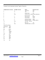
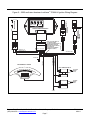
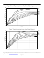
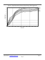
Twin Tec Installation Instructions for TC88A-IH Ignition CAUTION: CAREFULLY READ INSTRUCTIONS BEFORE PROCEEDING. NOT LEGAL FOR USE OR SALE ON POLLUTION CONTROLLED VEHICLES. OVERVIEW Carbureted American IronHorse Motorcycles use a non-adjustable ignition system manufactured in England by Gill. Twin Tec now offers the TC88A-IH version of our proven TC88A ignition that is compatible with 2004-2007 American IronHorse models. The TC88A-IH version has special firmware that provides the tach signal required by the IronHorse instrument module and proper dwell control for the original equipment (OE) ignition coils. You cannot use a standard TC88A unit. Installation involves cutting off the OE 18 terminal AMP connector used with the Gill module and replacing it with a 12 terminal Deustch connector supplied with the TC88A-IH kit. On 2005 and later models, some minor rewiring of the MAP sensor and engine temperature sensor ground connections is required. The TC88A-IH offers adjustable advance and adjustable RPM limit settings in 100 RPM increments. The TC88A-IH also features built-in data logging that stores data for the last 30 minutes of engine operation including RPM, manifold pressure, ignition advance, and battery voltage. Engine builders will find the data logging feature highly useful for tuning, diagnosing problems, and reducing unjustified warranty claims. Figure 1 – TC88A-IH Ignition Module Twin Tec PC link software along with an optional USB interface cable (P/N USB-INTF) and power adapter (TC88A-ADAPT) allow the use of a laptop PC to program a custom advance curve for precise dyno tuning and download data logged by the unit. INSTALLATION OVERVIEW Before proceeding you must have access to a proper Deutsch crimping tool and experience with the Deutsch connectors. For more information, you can refer to the Deutsch connector section in any recent Harley-Davidson electrical diagnostic manual. Ladd Industries (www.laddinc.com) sells a low cost crimping tool, Deutsch P/N DTT-16-00. On 2005 and later models, some wires will have to be extended. Solder all wire joints and cover with shrink tubing. PRE-INSTALLATION CHECK FOR CORRECT CRANKSHAFT POSITION SENSOR AIR GAP Customers have frequently encountered problems with the crankshaft position (CKP) sensor air gap. The S&S Cycle engine used on American IronHorse motorcycles does not have the same tolerances for the CKP sensor mounting as a standard H-D Twin-Cam. The same applies to the Gill CKP sensor. You must check the CKP sensor air gap. The sensor output voltage is proportional to RPM and drops off sharply as the air gap increases. The air gap must be .030-.045" for proper system operation. If the air gap is greater than .045", the ignition module will not trigger correctly at low cranking RPM. Remove the CKP sensor. Use a dial caliper to measure the clearance between the sensor mounting surface on the engine crankcase and the top of the flywheel teeth. Then measure the length of the sensor from the sensor flange to the tip. The air gap is the difference between these two measurements. If the air gap exceeds .045”, it must be corrected by machining or filing some material from the bottom of the sensor flange (to cause the sensor tip to protrude further into the crankcase). Daytona Twin Tec LLC, 933 Beville Road, Suite 101-H, S. Daytona, FL 32119 (386) 304-0700 www.daytona-twintec.com Page 1 TC88A-IH 9/2011 INSTALLATION ON 2004 MODELS 1. Turn off the ignition switch and disconnect the battery ground cable before proceeding. 2. Refer to Figures 2 and 3 for wiring details. 3. Remove the Gill Module. 1. Cut off the OE 18 terminal AMP connector used with the Gill module. Refer to the terminal list. Crimp new Deutsch terminals on the wires, and install into the 12 terminal Deutsch connector required by the TC88A-IH module. Any additional unused black ground wires can be removed or taped up. 4. Install the new TC88A-IH module. 5. Reconnect the battery ground cable. INSTALLATION ON 2005 AND LATER MODELS 2. Turn off the ignition switch and disconnect the battery ground cable before proceeding. 3. Refer to Figures 4 and 5 for wiring details. 4. Remove the Gill Module. 5. Cut off the OE 18 terminal AMP connector used with the Gill module. 6. The crankshaft position (CKP), MAP, and engine temperature (ET) sensor share a common ground return. This is not compatible with the TC88A-IH and some rewiring will be required. The temperature sensor is not used, but does not require removal. 7. Trace the BK/GN ground return wires from terminal B of the ET sensor and terminal A of the MAP sensor to where they join the BK/GY ground return wire from the CKP sensor. Cut the ET and MAP sensor ground return wires off at this point. You can tape up the ground return wire from the ET sensor – this wire will not be used. 8. Extend the ground return wire from terminal A of the MAP sensor up to the ignition module, crimp on a Deutsch terminal and install in position 4 on the Deutsch connector. 9. Refer to the terminal list. Crimp new Deutsch terminals on the remaining wires, and install into the 12 terminal Deutsch connector required by the TC88A-IH module. Any additional unused black ground wires can be removed or taped up. 10. Use a DVM to verify isolation (no continuity) between terminals 4 and 9 on the Deutsch connector. 11. Verify continuity between terminal A at the MAP sensor and terminal 4 on the Deutsch connector. 12. Verify continuity between terminal 2 at the CKP sensor and terminal 9 on the on the Deutsch connector. 13. Install the new TC88A-IH module. 14. Reconnect the battery ground cable. Daytona Twin Tec LLC, 933 Beville Road, Suite 101-H, S. Daytona, FL 32119 (386) 304-0700 www.daytona-twintec.com Page 2 TC88A-IH 9/2011 Terminal List for American IronHorse Ignition Conversion TC88A Deutsch Connector OE AMP Connector Signal Wire Color Code 1 2 +12V Power W/R 2 15 Tach W/V 3 4 Sensor Power GN 4 N/A Sensor Ground – 2005 and later models only 5 1 Module Ground BK 6 8 Coil Front (#1) BN/GY 7 14 Coil Rear (#2) GY/R 8 6 CKP Sensor Signal R/BK 9 5 CKP Sensor Return BK/GN or BK/GY 10 N/A VSS Input – not used 11 17 MAP Input 12 N/A J1850 Serial Data – not used Y/R Wire Color Codes Color Code BK BN R O Y GN BE V GY W PK TN Color Black Brown Red Orange Yellow Green Blue Violet Gray White Pink Tan Daytona Twin Tec LLC, 933 Beville Road, Suite 101-H, S. Daytona, FL 32119 (386) 304-0700 www.daytona-twintec.com Page 3 TC88A-IH 9/2011 MAP SENSOR Figure 2 – 2004 American IronHorse OE Ignition Wiring Diagram CRANKSHAFT POSITION (CKP) SENSOR GILL IGNITION MODULE CONNECTOR PIN NUMBERS (WIRE ENTRY SIDE VIEW) 18 17 16 15 12 6 B 5 4 14 13 9 3 8 2 7 1 A 1 2 17 4 1 2 8 14 6 5 15 C 11 10 MAP INPUT Y/R SENSOR PWR GN CKP SIGNAL R/BK SENSOR GND COIL REAR GY/R +12V POWER W/R INSTRUMENT CLUSTER TACH W/V GROUND BK COIL FRONT BN/GY CKP RETURN BK/G GILL IGNITION COILS TO FRONT SPARK PLUG TO REAR SPARK PLUG TO +12V Daytona Twin Tec LLC, 933 Beville Road, Suite 101-H, S. Daytona, FL 32119 (386) 304-0700 www.daytona-twintec.com Page 4 TC88A-IH 9/2011 Figure 3 – 2004 American IronHorse TC88A-IH Ignition Wiring Diagram 901 901 901 78 78 901 78 MAP SENSOR 23 456 23 456 23 456 456 23 78 INITIAL ADVANCE X1000 X100 MODE TIMING SLOPE RPM LIMIT ADJUST CRANKSHAFT POSITION (CKP) SENSOR TC88A-IH IGNITION MODULE B A 1 2 11 3 5 1 6 7 8 9 2 C MAP INPUT Y/R SENSOR PWR GN CKP SIGNAL R/BK CKP RETURN BK/GY COIL REAR GY/R +12V POWER W/R INSTRUMENT CLUSTER TACH W/V GROUND BK COIL FRONT BN/GY SENSOR GND GILL IGNITION COILS TO FRONT SPARK PLUG TO REAR SPARK PLUG TO +12V Daytona Twin Tec LLC, 933 Beville Road, Suite 101-H, S. Daytona, FL 32119 (386) 304-0700 www.daytona-twintec.com Page 5 TC88A-IH 9/2011 GILL IGNITION MODULE CRANKSHAFT POSITION (CKP) SENSOR ENGINE TEMP (ET) SENSOR MAP SENSOR Figure 4 – 2005 and Later American IronHorse OE Ignition Wiring Diagram 17 16 15 12 6 B 5 4 14 13 9 3 8 2 7 1 A 17 4 1 2 8 14 6 5 15 18 C 11 10 ET SIGNAL PK/Y 18 MAP INPUT Y/R SENSOR PWR GN ET RETURN BK/GN CONNECTOR PIN NUMBERS (WIRE ENTRY SIDE VIEW) 1 2 CKP SIGNAL R/BK SENSOR GND COIL REAR GY/R +12V POWER W/R INSTRUMENT CLUSTER TACH W/V GROUND BK COIL FRONT BN/GY CKP RETURN BK/GY GILL IGNITION COILS TO FRONT SPARK PLUG TO REAR SPARK PLUG TO +12V Daytona Twin Tec LLC, 933 Beville Road, Suite 101-H, S. Daytona, FL 32119 (386) 304-0700 www.daytona-twintec.com Page 6 TC88A-IH 9/2011 Figure 5 – 2005 and Later American IronHorse TC88A-IH Ignition Wiring Diagram 78 78 INITIAL ADVANCE X1000 X100 MODE TIMING SLOPE RPM LIMIT ADJUST TC88A-IH IGNITION MODULE A MAP INPUT Y/R SENSOR PWR GN B ET RETURN BK/GN B 11 3 5 1 6 7 8 4 2 9 C ET SIGNAL PK/Y A NOTE: CUT AND TAPE UP ET SENSOR LEADS. ISOLATE CKP RETURN AND MAP SENSOR GROUND. TEST WITH DVM TO VERIFY ISOLATION (NO CONTINUITY) BETWEEN TERMINALS 4 AND 9. X X SENSOR GND BK/GN CRANKSHAFT POSITION (CKP) SENSOR ENGINE TEMP (ET) SENSOR 901 901 901 78 901 78 MAP SENSOR 23 456 23 456 23 456 456 23 1 2 CKP SIGNAL R/BK COIL REAR GY/R +12V POWER W/R INSTRUMENT CLUSTER TACH W/V GROUND BK COIL FRONT BN/GY CKP RETURN BK/GY GILL IGNITION COILS TO FRONT SPARK PLUG TO REAR SPARK PLUG TO +12V Daytona Twin Tec LLC, 933 Beville Road, Suite 101-H, S. Daytona, FL 32119 (386) 304-0700 www.daytona-twintec.com Page 7 TC88A-IH 9/2011 RECOMMENDED TIMING SETTINGS The American IronHorse engine utilizes a nonadjustable crankshaft position sensor. Thus no mechanical means exist for adjusting the timing. The TC88A-IH module overcomes this limitation. The initial timing switch allows you to shift the entire advance table up or down. Lower switch settings decrease (retard) the initial timing and higher switch settings increase (advance) the initial timing in one-degree steps. The TC88A-IH module accommodates a wide range of engine applications. The advance slope switch allows you to control the aggressiveness of the ignition advance. Figures 6-8 show the effect of advance slope switch settings. Each figure shows advance curves for various manifold pressure values. Higher switch settings result in more aggressive advance. The effect is more pronounced at high manifold pressures. Note that 30 In-Hg manifold pressure represents wide open throttle (WOT) and 16 In-Hg represents deceleration conditions. For most applications, initial timing setting 2 and advance slope setting 1 should eliminate any spark knock encountered with stock engines. The TC88A Tech FAQ on our website also has a custom advance table that you can download for modified high compression IronHorse applications provided by courtesy of Proven Performance. Tuning a particular engine setup always requires some trial and error experimentation, but maximum power is usually obtained by using the highest advance settings possible without audible spark knock. If you experience spark knock only at low RPM, you can try reducing the initial timing switch setting while maintaining an aggressive advance slope for maximum power at high RPM by increasing the advance slope switch setting. If spark knock is a problem at high RPM, decrease the advance slope switch setting. Once you have determined the best switch settings, you can further optimize the timing at a particular RPM or manifold pressure by programming a custom advance curve with our PC Link software and optional interface cable. RPM LIMITER SETTING You can set the RPM limit from 3,000 to 9,900 RPM in 100 RPM increments by means of two rotary switches. The RPM limit is X100 switch setting (i.e. 57 = 5,700 RPM). Inadvertent settings below 3,000 RPM are ignored and result in a 3,000 RPM limit. Setting the RPM limit switches to zero will disable the module. The TC88A-IH module uses a newly developed RPM limiting algorithm that has been highly optimized for odd firing V twin engines. When the engine is held against the RPM limit, cylinder firing is always paired. This eliminates a torque couple and results in very smooth operation compared to random or sequence type RPM limiters. Set a safe RPM limit that is appropriate for your engine. Most engines with OE valvetrain components should not be run over 5,700 RPM. GENERAL RECOMMENDATIONS The TC88A-IH is designed to be used only with the OE Gill coils. Due to the short lengths involved on motorcycle applications, energy losses in spark plug wires are insignificant. OE carbon core suppression cables will deteriorate after several years. For a more durable replacement, we suggest spiral core type spark plug cables. CAUTION: Do not use solid copper spark plug cables or non-resistor type spark plugs. The unit may misfire. CUSTOM ADVANCE TABLE TUNING TIP: Lean air/fuel ratio (AFR) increases the tendency for spark knock. Check AFR and rejet carburetor before optimizing ignition timing. Test the motorcycle on a dyno with an exhaust gas sniffer or use our WEGO. PC Link TC88 software allows you to program a custom advance table and modify certain engine control parameters. An optional USB interface cable (P/N USB-INTF) and adapter harness (P/N TC88AADAPT) that includes a small 12 volt power supply is required. For more details, refer to the PC Link TC88 documentation. The latest versions of Twin Tec software and documentation are always available for download on our website. The software is free and will Daytona Twin Tec LLC, 933 Beville Road, Suite 101-H, S. Daytona, FL 32119 (386) 304-0700 www.daytona-twintec.com Page 8 TC88A-IH 9/2011 work in demo mode without a TC88A-IH module attached. If you program a custom advance curve, make sure that you leave the tach output enabled under module parameters (refer to PC Link TC88 instructions for details), otherwise the tach will not function. DIAGNOSTICS AND DATA LOGGING The TC88A-IH features built-in data logging that stores data for the last 30 minutes of engine operation including RPM, vehicle speed, manifold pressure, ignition advance, and battery voltage. Engine builders will find the data logging feature highly useful for tuning, diagnosing problems, and reducing unjustified warranty claims. TC88A Log software allows you to access the data logging feature. TC88A Log software also allows you to view engine data in real time and display operating statistics and historical diagnostic codes. An optional USB interface cable (P/N USBINTF) and adapter harness (P/N TC88A-ADAPT) that includes a small 12 volt power supply is required. For more details, refer to the TC88A Log documentation. The latest versions of Twin Tec software and documentation are always available for download on our website. The software is free and will work in demo mode without a TC88A-IH module attached. The IronHorse vehicle speed sensor is not compatible with the TC88A-IH, thus no speed data will be logged by the module. If you use the TC88A Log software, vehicle speed will always appear as zero. Note that installation of the TC88A-IH does not affect normal operation of the IronHorse speedometer. TROUBLESHOOTING Customers sometimes find that the original problem is not corrected after installation of TC88A-IH modules on motorcycles that would not start or were not running properly. If the motorcycle will not start after installation of a TC88A-IH, follow the steps below: 1. If you have not already done so, check the crankshaft position sensor air gap as explained on page 1. 2. Use a DVM to check continuity of all electrical connections from end-to-end (i.e. from the ignition module connector to all other connectors including ground). 2005 and later models: verify isolation (no continuity) between terminals 4 and 9 on ignition module connector. 3. All 2004 and later models have a 36 pin relay harness controller (RHC) that controls power to the ignition system. Failure of the RHC is often misdiagnosed as an ignition failure. Refer to Figure 3 or 5. Connect a jumper wire from one of the Coil+ terminals direct to battery positive. If the engine can now be started, the RHC is defective. Wire Plus (www.wire-plus.com) offers a suitable replacement part. 4. MAP sensor. If MAP sensor power is shorted to ground, the module will not function. Try removing terminal 3 (green wire) from the module connector. If the engine now starts, a short circuit exists or the MAP sensor has failed. During normal operation of the MAP sensor, the MAP signal voltage levels at terminal 11 (yellow/red wire) will be approximately 4.8V (ignition on/engine not running) and 1.2-1.8V (engine at idle). At significant elevations, these voltage levels will be somewhat lower. 5. Coils. The original equipment coils are generally reliable. If the engine runs on one cylinder, try swapping coils. If the problem stays with the same cylinder, suspect a wiring fault or engine valvetrain issue. If the problem moves the the opposite cylinder, the coil is defective. Nology (www.nology.com) P/N PFC-06S 0.6 ohm single tower coil can be used as a direct replacement part. TROUBLESHOOTING FLOWCHART If the motorcycle was running properly before installation of the TC88A-IH, follow the troubleshooting flowchart on page 12. Experience has shown that most units returned for warranty are OK and another problem, such as a defective coil or user error, is later identified. Daytona Twin Tec LLC, 933 Beville Road, Suite 101-H, S. Daytona, FL 32119 (386) 304-0700 www.daytona-twintec.com Page 9 TC88A-IH 9/2011 Figure 6 - Graph Representing Advance Slope Setting 0 (Least Aggressive) 45 16 IN-HG 18 IN-HG DECEL 40 20-INHG 22 IN-HG 24 IN-HG 26 IN-HG 28 IN-HG 30 IN-HG 35 ADVANCE (DEG) 30 25 WOT 20 15 10 5 0 0 500 1000 1500 2000 2500 3000 3500 4000 4500 5000 5500 ENGINERPM Figure 7 - Graph Representing Advance Slope Setting 5 (Nominal) 45 16 IN-HG 18 IN-HG DECEL 40 20-IN HG 22 IN-HG 24 IN-HG 26 IN-HG 35 28 IN-HG 30 IN-HG ADVANCE (DEG) 30 WOT 25 20 15 10 5 0 0 500 1000 1500 2000 2500 3000 3500 4000 4500 5000 5500 ENGINE RPM Daytona Twin Tec LLC, 933 Beville Road, Suite 101-H, S. Daytona, FL 32119 (386) 304-0700 www.daytona-twintec.com Page 10 TC88A-IH 9/2011 Figure 8 - Graph Representing Advance Slope Setting 9 (Most Aggressive) 45 16 IN-HG 18 IN-HG 20-IN HG 22 IN-HG 24 IN-HG 26 IN-HG 28 IN-HG 30 IN-HG DECEL 40 35 WOT ADVANCE (DEG) 30 25 20 15 10 5 0 0 500 1000 1500 2000 2500 3000 3500 4000 4500 5000 5500 ENGINE RPM Daytona Twin Tec LLC, 933 Beville Road, Suite 101-H, S. Daytona, FL 32119 (386) 304-0700 www.daytona-twintec.com Page 11 TC88A-IH 9/2011 Troubleshooting Flowchart STARTING POINT REPLACE TC88A WITH ANOTHER KNOWN GOOD MODULE. DOES ENGINE START? YES NO REPAIR UNDERLYING PROBLEM BEFORE REINSTALLING TC88A. REFER TO MOTORCYCLE SERVICE MANUAL REINSTALL TC88A DOES ENGINE START? NO YES USE TC88A LOG SOFTWARE TO CHECK FOR DIAGNOSTIC CODES. ARE ANY CODES SET? REPLACE TC88A NO YES REFER TO TC88A DIAGNOSTICS SECTION. FIX APPLICABLE PROBLEM. DOES ENGINE STOP OR DROP CYLINDER AFTER SEVERAL MINUTES OF RUNNING? NO YES REPLACE COILS. IS PROBLEM FIXED? YES DOES ENGINE MISFIRE UNDER LOAD? NO NO REPLACE TC88A DONE YES REPLACE SPARK PLUGS, SPARK PLUG WIRES, AND COILS IS PROBLEM FIXED? YES DONE NO REPLACE TC88A DOES ENGINE MISFIRE AT PART THROTTLE OR WHILE COLD? NO FOR MISC PROBLEMS, CALL TECH SUPPPORT. YES CHECK FOR INCORRECT CARB JETTING OR INTAKE LEAK. IS PROBLEM FIXED? YES DONE NO REPLACE TC88A Daytona Twin Tec LLC, 933 Beville Road, Suite 101-H, S. Daytona, FL 32119 (386) 304-0700 www.daytona-twintec.com Page 12 TC88A-IH 9/2011