1
March, 2003
hp storage
Installation guide for the b3000 v1
technical
white paper
table of contents
This guide will provide the steps necessary to install and configure a StorageWorks NAS
b3000 v1. This guide uses Quick Restore version 2.12 for the b3000. The purpose of this
document is to guide customers and field engineers in the procedures required to install
NAS distribution software and then update the system with current service packs, hotfixes,
and SoftPaqs relevant to the StorageWorks NAS products. This guide is for new
installations only, and does not contain steps for migrating data from an existing
installation.
Introduction
Quick Restore
Rapid Launch
Configuring and Updating the System
Rapid Startup
SAN Connection Tool
2
2
2
4
4
6
Patching SWVR in a non-clustered architecture
Installing Cluster Services
6
8
Connecting to MSA1000
Checklists for Cluster Server Installation
Shared Disk Requirements:
Installation Overview
Setting up Networks
Configure the Public Network Adapter
Install Cluster Service Software
Configuring the First Node
Validating the Cluster Installation
Configuring the Second Node
Verify Installation
6
8
8
9
9
11
12
12
18
19
20
Upgrading SWVR and SFU to be cluster aware
Creating Pools and Virtual Disks
22
25
Creating Cluster Virtual Servers and Cluster aware file share resources.
25
Creating a SWVR Pool through the WEBUI
Creating a Virtual Server with the WEBUI
25
26
1
[Enter your Document Title]
[Document Restriction Notice]
Creating a Virtual Server with Terminal Services
Creating Cluster File Share Resources with the WEBUI
Creating Cluster File Share Resources with Terminal Services
26
27
27
2
[Enter your Document Title]
[Document Restriction Notice]
Introduction
This paper will provide a step-by-step process for the installation and configuration of the
b3000 v1. It is assumed that the installation will be preformed on a new unit or a unit
that has just been quick restored. Additional information about any of the topics covered
in the document can be located in the Administration guides for the respective products.
Quick Restore
The NAS b3000 v1 Quick Restore CD should be labeled version 2.12.
1. Place the StorageWorks NAS Executor b3000 Quick Restore CD into the
CDROM drive on the b3000. With the CD in the CDROM tray, reboot or turn
on the server. When prompted press “Q” to begin the Quick Restore.
2. When prompted for the second CD, insert the second CD.
If the b3000 being installed is part of a cluster, save time by placing CD 1 into the
second node after it completes on the first node, and start the Quick Restore process.
The Quick Restore process is automated and it is not necessary to interact with the nodes
during the restore process.
Rapid Launch
The NAS b3000 includes a RapidLaunch CD that can run on any Windows-based PC
using Internet Explorer 5.5 (or greater). The WebUI application is designed to be
graphical and easy-to-use, and to assist you in populating information necessary for
configuration.
NOTE: The RapidLaunch utility must be run on each node in a cluster.
Requirements
The following items are required to run the WebUI configuration application:
• Windows-based PC loaded with Internet Explorer 5.5 (or greater) on the same
network segment as the NAS b3000
• RapidLaunch CD
NOTE: The NAS b3000 is designed to be deployed without a monitor, keyboard, and mouse.
These ports are available and supported by the NAS device if used.
To initialize the NAS b3000 using the WebUI configuration application:
CAUTION: Do not power up the NAS device until steps 1-5 are completed.
1. Connect the Ethernet cables to the respective network ports of the NAS b3000.
2. Verify that the Windows-based PC client is connected to the same subnet as
the NAS b3000.
3. Power on the Windows-based PC and wait until the operating system has
completely loaded.
4. Insert the RapidLaunch CD into the CD-ROM drive.
5. The RapidLaunch CD should automatically run. If the program does not
startup automatically, the program may be run manually. Click Start select Run
on the Windows taskbar, and then type the following: {CD ROM
drive}:\setup.exe. Wait for the interface to startup.
6. Go to the NAS device and power it on. It will be several minutes before the
NAS device is accessible on the network.
7. Return to the Windows-based PC. Select StorageWorks NAS from the Show
drop down list to have RapidLaunch list all NAS devices on the network.
8. All the NAS devices found on the network are displayed. The NAS device will
be displayed in the device discovery portion of the screen as an unconfigured
device. It may take several minutes for the NAS device to be found on the
2
[Enter your Document Title]
[Document Restriction Notice]
network.
NOTE: The RapidLaunch utility will refresh periodically looking for new devices on the network.
You may refresh the device list manually by selecting the Refresh button.
9. Select the unconfigured StorageWorks NAS device from the device list. This
launches the WebUI configuration application (Rapid Startup) on the target
StorageWorks NAS device.
10. Follow the instructions on the screen to input the correct information. Verify
that your information is correct when the configuration review screen is
displayed.
11. Click the Online icon to save the network information to the NAS b3000.
12. Click the Finish icon to exit Rapid Startup. Close the browser window. The
NAS b3000 will now reboot to set the configuration information.
13. If the NAS b3000 is being deployed in a cluster configuration, go back to the
RapidLaunch utility program and select the next unconfigured NAS device to
be used within the cluster and repeat steps 8-12 for the second node.
14. Exit the RapidLaunch utility and remove the RapidLaunch CD from the CDROM drive and store it in a secure location.
3
[Enter your Document Title]
[Document Restriction Notice]
Configuring and
Updating the
System
NOTE: In a cluster configuration, from this point forward, the first node will be referred
to as NODE A and the second node will be referred to as NODE B.
The Rapid Launch utility allows an administrator to configure the nodes network
configurations from a client before the Quick Restore process. The configuration is saved
to a floppy, which may be inserted into the node during the Quick Restore process. This
is an optional configuration method, and if a floppy has not been inserted then a screen
will appear with three options when the Quick Restore is completed. If a diskette was not
created select IGNORE and then CONTINUE, select YES to complete the utility.
Download and install the StorageWorks NAS Cluster Setup Tool update from the
following link:
http://h18006.www1.hp.com/support/files/server/us/download/14994.html
Download and install the Compaq StorageWorks NAS Services For Unix version 2.3
and WebUI update from the following link:
http://h18006.www1.hp.com/support/files/server/us/download/15012.html
This will reboot the node.
After the reboot has completed navigate to C:\sfu23. Right click on info.inf and select
install.
Download and install the StorageWorks NAS Data Copy fix for uninstall problem from
the following link:
http://h18006.www1.hp.com/support/files/server/us/download/17535.html
Install SP3 or any other hot fixes required to be installed.
Note: At the link above, there are other software updates available that do not apply
to this configuration. Install only the items specifically mentioned here. Do not install the
SWVR patch 1, SWVR patch 2 or the Compaq StorageWorks Virtual Replicator Service
Patch 116B. They are all installed with the image. The Compaq SANworks Virtual
Replicator Update will be applied later in the configuration. (SoftPaq 2829)
Note: Complete this process on both nodes.
Rapid Startup
From a remote node, open an Internet Explorer session and navigate to the WEBUI for
StorageWorks NAS. The WEBUI is accessible through the hostname and port 3201. For
example http://hostname:3201.
The Rapid Startup Utility is provided to allow a quick setup of the network connections.
The Rapid Startup Utility will be the first page displayed when the WEBUI is opened.
Rapid Startup will allow for the configuration of all network adapters and the Remote
Insight Board. The Rapid Startup Utility is accessible through the WEBUI.
1. Click on the Internet Explorer icon in the fast start tray. Navigate to
http://hostname:3201. A prompt for a username and password will appear.
The user name is administrator, there is no password. The password is the same
password that is used for the local administrator account on the server, so if the
password has been changed for the local administrator’s account it must also be
used to login into the WEBUI.
2. Complete the Rapid Startup by filling in the appropriate information in the fields
provided.
3. Once rapid start is complete the node will reboot.
4
[Enter your Document Title]
[Document Restriction Notice]
NOTE: Make sure to run the Rapid Startup Utility on both nodes before
continuing
5
[Enter your Document Title]
[Document Restriction Notice]
SAN Connection
Tool
The SAN Connection Tool is a utility which configures the nodes for connection to a
StorageWorks SAN. The SAN Connection tool is accessible through the WEBUI and
must be completed after the Rapid Startup utility. No Fiber cables should be connected
to the node at this time and the nodes should remain unconnected until after the SAN
Connection Tool process is completed.
From a remote node, click on the Internet Explorer icon in the fast start tray. Navigate to
http://hostname:3201. A prompt for a username and password will appear. The user
name is administrator, the password should be null if this is a new install (the password
is the same password that is used for the local administrator account on the server).
Verify that no fiber cables are connected to the HBAs.
The StorageWorks NAS b3000 v1 uses the HP StorageWorks Modular SAN
Array 1000 (MSA1000) storage subsystem.
Connecting to MSA1000
1. Open lputilnt from a run command and verify that the HBA driver is 5-4.82a9
and the firmware is 3.81a1
2. Select Next and the tool will install the necessary components
3. Secure path v3.1b will be installed with this utility.
NOTE: Make sure to do this on both nodes before continuing.
IMPORTANT: Connect the NAS system(s) to the MSA1000 Storage subsystem at this
time.
Patching SWVR
in a nonclustered
architecture
This section is for a stand-alone architecture. If the b3000 is to be clustered skip to the
next section entitled “Installing Cluster Services”.
The only patch required is the Compaq SANworks Virtual Replicator Update. (SoftPaq
2829)
http://h18006.www1.hp.com/support/files/server/us/download/16247.html
Installation Instructions for stand-alone systems:
1. Place the Smart Component in a temporary directory on the NAS system, then doubleclick it to run.
2. Click 'Install' at the Compaq Package Setup screen.
3. Click 'Install' at the Compaq Setup screen.
4. All the necessary files will be extracted to C:\CP002829.
5. Browse to "C:\Winnt\System32\Drivers."
6. Rename the file CPQVRBus.sys to CPQVRBus.sys.bak.
7. Copy the file "C:\CP002829\CPQVRBus.sys" to the directory
"C:\Winnt\System32\Drivers."
8. Browse to "C:\Program Files\Compaq\SANWorks Virtual Replicator 2.5\WDM"
9. Rename the file CPQVRBus.sys to CPQVRBus.sys.bak.
10. Copy the file "C:\CP002829\CPQVRBus.sys" to the directory C:\Program
Files\Compaq\SANWorks Virtual Replicator 2.5\WDM"
11. Browse to "C:\Winnt\System32."
6
[Enter your Document Title]
[Document Restriction Notice]
12. Rename the file Sdapi.dll to Sdapi.dll.bak.
13. Copy the file "C:\CP002829\Sdapi.dll to the directory "C:\Winnt\System32."
14. Browse to "C:\Program Files\Compaq\SANWorks Virtual Replicator 2.5."
15. Rename the file Sdapi.dll to Sdapi.dll.bak.
16. Rename the file VRRegMon.exe to VRRegMon.exe.bak.
17. Copy the file "C:\CP002829\Sdapi.dll to the directory "C:\Program
Files\Compaq\SANWorks Virtual Replicator 2.5."
18. Copy the file "C:\CP002829\VRRegMon.exe to the directory "C:\Program
Files\Compaq\SANWorks Virtual Replicator 2.5."
19. Restart the system.
7
[Enter your Document Title]
[Document Restriction Notice]
Installing Cluster
Services
This section is for installing and configuring cluster services. If the b3000 is not to be
part of a cluster, skip this section.
It is possible to configure cluster services remotely through the WEBUI using the Cluster
Setup Tool. To access the Cluster Setup Tool open an Internet Explorer session from the
remote client and navigate to http://hostname:3201. Once the WEBUI is open select
the link form the left hand side labeled Cluster Setup Tool. Follow the instructions in the
Cluster Setup Tool to configure the cluster configuration.
Confirm that the following specifications have been met before proceeding:
•
When configuring the b3000 v1 in a cluster with MSA storage, it is highly
recommended that the MSA controllers are upgraded to v2.38 or higher. A
utility can be downloaded from the following location to update the MSA
firmware:
o
http://h18006.www1.hp.com/products/storageworks/softwaredrivers
/msa1000/v238.html
•
The SAN Connection Tool must be completed and all the necessary software
components for connecting to the desired storage must be installed before the
configuration of cluster services.
•
At least one LUN must be presented for the configuration of the Quorum disk.
Additional LUNS may also be presented for use as shared disk resources.
•
Do not present LUNs to both cluster nodes until after cluster services have been
installed.
More detailed information about setting up clusters is available at
http://www.microsoft.com/windows2000/techinfo/planning/server/clustersteps.asp
Since each cluster node will be shut down one or more times during this installation,
print this guide, or copy it elsewhere and view it on a separate system.
Checklists for Cluster Server Installation
This checklist assists in preparing for installation. Step-by-step instructions begin after the
checklist.
Network Requirements:
•
A unique NetBIOS cluster name.
•
Five unique, static IP addresses: two for the network adapters on the private
network, two for the network adapters on the public network, and one for the
cluster itself.
•
A domain user account for the Cluster service (all nodes must be members of the
same domain).
•
Each node should have at least two network adapters—one for connection to
the node-to-node private cluster network and the others for the public data
network. Do not attempt to use a single network adaptor for both public and
private cluster communications.
Shared Disk Requirements:
Note: Do not let both nodes access the shared storage devices at the same time until
after the Cluster service is installed on at least one node and that node is online. This can
8
[Enter your Document Title]
[Document Restriction Notice]
be accomplished through selective storage presentation, SAN switch zoning or having
only one node online at all times.
•
All software components listed in the SAN connection tool must be installed and
the fiber cables attached to the HBA(s) before the cluster installation is started.
•
All shared disks, including the quorum disk, must be accessible from both nodes.
However, do not let the shared disk be accessed by both nodes at the same time
until Cluster Services has been installed on at least one node.
•
All shared disks must be configured as basic (not dynamic).
•
All partitions on the disks must be formatted as NTFS.
Installation Overview
During the installation process, both nodes will be shut down and both nodes
will be rebooted. These steps are necessary to guarantee that the data on disks
that are attached to the shared storage bus is not lost or corrupted. This can
happen when multiple nodes try to simultaneously write to the same disk that is
not yet protected by the cluster software.
Use Table 1 below to determine which nodes and storage devices should be
presented during each step.
Step
Node 1
Node 2
Storage
Comments
Setting Up
Networks
On
On
Not
Presented
Verify that all storage devices on the shared
bus are not presented.
Power on both nodes.
Setting up Shared
Disks
On
Off
Presented
Shutdown both nodes.
Present the shared storage
Power on the first node.
Verifying Disk
Configuration
Off
On
Presented
Shut down first node.
Power on second node.
Configuring the
First Node
On
Off
Presented
Shutdown all nodes.
Power on the first node.
Configuring the
Second Node
On
On
Presented
Power on the second node after the first node
was successfully configured.
Post-installation
On
On
Presented
At this point all nodes should be on.
Table 1. Power Sequencing for Cluster Installation
To configure the Cluster service on the StorageWorks NAS server, the login
account must have administrative permissions on each node. Both nodes must
be member servers within the same domain.
Setting up Networks
9
[Enter your Document Title]
[Document Restriction Notice]
Note: Do not let both nodes access the shared storage devices at the same time
until the Cluster service is installed on at least one node and that node is
online. This can be accomplished through selective storage presentation, SAN
switch zoning or having only one node online at all times.
Each cluster node requires at least two network adapters—one to connect to a
public network, and one to connect to a private network consisting of cluster
nodes only.
The private network adapter establishes node-to-node communication, cluster
status signals, and cluster management. Each node’s public network adapter
connects the cluster to the public network where clients reside.
Verify that all network connections are correct, with private network adapters
connected to other private network adapters only, and public network adapters
connected to the public network.
Configure the Private Network Adapter
The following procedures are Best Practices provided by Microsoft and should
be configured on the private network adapter.
•
On the General tab of the private network adapter, ensure that only TCP/IP is selected
•
Under the advanced settings for the private network adapter, select the DNS Tab. Ensure
that the register this connections address in DNS is not selected.
•
Open the advanced tab for the Ethernet card used for the private network adapter.
Ensure that the Link Speed and Duplex is set to 100Mps/Full Duplex
•
If a crossover cable is used for the private adapter and since one node will be powered
down during the cluster installation. The private network adapter will be in a
disconnected state during installation, the Cluster service does not detect the adapter
because there are no protocols bound to the adapter. If Media Sense is disabled the
network adapter still shows the "disconnected" status, but the cluster installation process
can detect the adapter as available for cluster communication. To make this change open
regedit and add the following Dword value:
o
HKEY_LOCAL
_MACHINE\SYSTEM\CurrentControlSet\Services\Tcpip\Parameters
o
Value Name: DisableDHCPMediaSense
o
Data Type: Reg_Dword
o
Data: 1
WARNING : Using Registry Editor incorrectly can cause serious problems that may
require you to reinstall your operating system. You should backup your Registry
before making any changes. Use Registry Editor at your own risk.
For information about how to backup, edit, and restore the Registry in Windows 2000,
see Microsoft Knowledge Base Article Q322755:
http://support.microsoft.com/default.aspx?scid=kb;EN-US;q322755
Note: If the private network connection is made using a crossover cable, then the
procedures outlined in Knowledge Base (KB) article Q242430
10
[Enter your Document Title]
[Document Restriction Notice]
(http://support.microsoft.com/support/kb/articles/Q242/4/30.ASP) should be
followed and the node rebooted prior to installing the Cluster service. If this procedure is
not completed, and the second node is powered off while installing the Cluster service
on the first node, the private network adapter may not be detected. This will prevent
configuring the adapter during the Cluster service installation. However, after the Cluster
service is installed on both nodes and both nodes are powered on, the adapter can be
added as a cluster resource and be configured properly for the private network in
Cluster Administrator.
Configure the Public Network Adapter
Note: While the public network adapter’s IP address can be automatically obtained if a
DHCP server is available, this is not recommended for cluster nodes. We strongly
recommend setting static IP addresses for all network adapters in the cluster, both private
and public. If IP addresses are obtained via DHCP, access to cluster nodes could
become unavailable if the DHCP server goes down. If you must use DHCP for your
public network adapter, use long lease periods to assure that the dynamically assigned
lease address remains valid even if the DHCP service is temporarily lost. In all cases, set
static IP addresses for the private network connector. Keep in mind that Cluster service
will recognize only one network interface per subnet. If you need assistance with TCP/IP
addressing in Windows 2000, please see Windows 2000 Online Help
(http://www.microsoft.com/windows2000/techinfo/proddoc/default.asp).
Rename the Local Area Network Icons
Change the names of the network connections for clarity. The naming will help
identify a network and correctly describes its role.
Verifying Connectivity and Name Resolution
To verify name resolution, ping each node from a client using the node’s
machine name instead of its IP address.
Verifying Domain Membership
Both nodes in the cluster must be members of the same domain and able to
access a domain controller and a DNS Server.
Setting Up a Cluster User Account
The Cluster service requires a domain user account under which the Cluster
service can run. This user account must be created before installing the Cluster
service, because setup requires a user name and password. This user account
should not belong to a user on the domain. This user account will need to be
granted administrator privileges.
About the Quorum Disk
Once both nodes have completely powered down, power up node A.
The quorum disk is used to store cluster configuration database checkpoints and
log files that help manage the cluster. The quorum disk must be a shared disk
resource. We make the following quorum disk recommendations:
11
[Enter your Document Title]
[Document Restriction Notice]
•
Create a small partition [A minimum of 50 megabytes (MB) to be used as a quorum disk.
We recommend a quorum disk have at least 1GB of free space.]
•
Dedicate a separate disk resource for a quorum disk. As the failure of the quorum disk
would cause the entire cluster to fail, it is strongly recommended that the disk resource be
a RAID 1 configuration.
During the Cluster service installation, a drive letter must be provided for the
quorum disk. It is recommended to use the drive letter Q for the quorum disk.
Configuring Shared Disks
Use Disk Management to configure the quorum and shared disk resources.
Verify that all shared disks are formatted as NTFS and are designated as Basic.
Verifying Disk Access and Functionality
Write a file to each shared disk resource to verify functionality.
At this time, shut down the first node, power on the second node and repeat the
Verifying Disk Access and Functionality step above. When it has been verified
that both nodes can read and write from the disks, shut down the second node
and power on the first, and then continue with this guide.
Install Cluster Service Software and Configuring the First Node
Note: During installation of Cluster service on the first node, the second node
must be shut down. All shared storage devices should be powered up.
In the first phase of installation, all initial cluster configuration information
must be supplied so that the cluster can be created. This is accomplished using
the Cluster Service Configuration Wizard.
1.
Click Start, click Settings, and click Control Panel.
2.
Double-click Add/Remove Programs.
3.
Double-click Add/Remove Windows Components.
4.
Select Cluster Service. Click Next.
5.
When prompted for files on the Windows Powered OS CD or the Windows 2000 SP3
cd, browse to the directory C:\Compaq\Windows Components\i386.
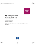
6.
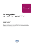
The window shown in Figure 7 below appears. Click I Understand to accept the
condition that the Cluster service is supported on hardware from the Hardware
compatibility List only.
12
[Enter your Document Title]
[Document Restriction Notice]
Figure 7. Hardware Configuration Certification Screen
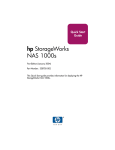
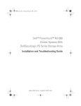
7. Because this is the first node in the cluster, the cluster must be created. Select the first
node in the cluster, as shown in Figure 8 below and then click Next.
13
[Enter your Document Title]
[Document Restriction Notice]
Figure 8. Create New Cluster
8.
Enter a name for the cluster (up to 15 characters), and click Next. (In our example, we
name the cluster MyCluster.)
9.
Type the user name and password of the cluster service account that was created
during the pre-installation. Type the domain name, and click Next.
At this point the Cluster Service Configuration Wizard validates the
user account and password.
10. Click Next.
Configuring Cluster Disks
Note: By default, all SCSI disks not residing on the same bus as the
system disk will appear in the Managed Disks list. Therefore, if the node
has multiple SCSI buses, some disks may be listed that are not to be
used as shared storage (for example, an internal SCSI drive.) Such disks
should be removed from the Managed Disks list.
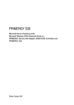
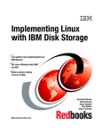
11. The Add or Remove Managed Disks dialog box shown in Figure 9 specifies which
shared disks will be used by Cluster service. Add or remove disks as necessary and then
click Next.
Figure 9. Add or Remove Managed Disks
The first partition of the first disk is selected as the quorum resource by
default. Change this to denote the small partition that was created as the
quorum disk (in our example, drive Q). Click Next.
14
[Enter your Document Title]
[Document Restriction Notice]
In production clustering scenarios more than one private network for
cluster communication must be used to avoid having a single point of
failure. Cluster service can use private networks for cluster status signals
and cluster management. This provides more security than using a
public network for these roles. It is possible to use a public network for
cluster management, or use a mixed network for both private and public
communications. In any case, make sure at least two networks are used
for cluster communication, as using a single network for node-to-node
communication represents a potential single point of failure. We
recommend that multiple networks be used, with at least one network
configured as a private link between nodes and other connections
through a public network. If you have more than one private network,
make sure that each uses a different subnet, as Cluster service
recognizes only one network interface per subnet.
This document is built on the assumption that only two networks are in
use. It shows how to configure these networks as one mixed and one
private network.
The order in which the Cluster Service Configuration Wizard presents
these networks may vary. In this example, the public network is
presented first.
12. Click Next in the Configuring Cluster Networks dialog box.
13. Make sure that the network name and IP address correspond to the network interface for
the public network.
14. Check the box Enable this network for cluster use.
15. Select the option All communications (mixed network) as shown in Figure 10
below.
16. Click Next.
15
[Enter your Document Title]
[Document Restriction Notice]
Figure 10. Public Network Connection
17. The next dialog box shown in Figure 11 configures the private network. Make sure that
the network name and IP address correspond to the network interface used for the private
network.
18. Check the box Enable this network for cluster use.
19. Select the option Internal cluster communications only.
16
[Enter your Document Title]
[Document Restriction Notice]
Figure 11. Private Network Connection
20. Click Next.
21. In this example, both networks are configured in such a way that both can be used for
internal cluster communication. The next dialog window offers an option to modify the
order in which the networks are used. Because Private Cluster Connection
represents a direct connection between nodes, it is left at the top of the list. In normal
operation this connection will be used for cluster communication. In case of the Private
Cluster Connection failure, cluster service will automatically switch to the next network
on the list—in this case Public Cluster Connection. Make sure the first connection in
the list is the Private Cluster Connection and click Next.
Important: Always set the order of the connections so that the Private Cluster Connection is
first in the list
22. Enter the unique cluster IP address and Subnet mask, and click Next.
17
[Enter your Document Title]
[Document Restriction Notice]
Figure 12. Cluster IP Address
The Cluster Service Configuration Wizard shown in Figure 12
automatically associates the cluster IP address with one of the public or
mixed networks. It uses the subnet mask to select the correct network.
23. Click Finish to complete the cluster configuration on the first node.
The Cluster Service Setup Wizard completes the setup process for the
first node by copying the files needed to complete the installation of
Cluster service. After the files are copied, the Cluster service registry
entries are created, the log files on the quorum resource are created, and
the Cluster service is started on the first node.
A dialog box appears telling you that Cluster service has started
successfully.
24. Click OK.
25. Close the Add/Remove Programs window.
Validating the Cluster Installation
Use the Cluster Administrator snap-in to validate the Cluster service installation
on the first node.
1. Click Start, click Programs, click Administrative Tools, and click
Cluster Administrator.
18
[Enter your Document Title]
[Document Restriction Notice]
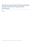
Figure 13. Cluster Administrator
If your snap-in window is similar to that shown above in Figure 13, your
Cluster service was successfully installed on the first node. It is now possible to
install the Cluster service on the second node.
Configuring the Second Node
Note: For this section, leave the first node on and power up the second node.
Installing Cluster service on the second node requires less time than on the first
node. Setup configures the Cluster service network settings on the second node
based on the configuration of the first node.
Installation of Cluster service on the second node begins exactly as for the first
node. During installation of the second node, the first node must be running.
Follow the same procedures used for installing Cluster service on the first node,
with the following differences:
1.
In the Create or Join a Cluster dialog box, select The second or next node in
the cluster, and click Next.
2.
Enter the cluster name that was previously created (in this example, MyCluster), and
click Next.
3.
Leave Connect to cluster as unchecked. The Cluster Service Configuration
Wizard will automatically supply the name of the user account selected during the
installation of the first node. Always use the same account used when setting up the first
cluster node.
19
[Enter your Document Title]
[Document Restriction Notice]
4.
Enter the password for the account (if there is one) and click Next.
5.
At the next dialog box, click Finish to complete configuration.
6.
The Cluster service will start. Click OK.
7.
Close Add/Remove Programs.
Verify Installation
There are several ways to verify a successful installation of Cluster service.
Here is a simple one:
1.
Click Start, click Programs, click Administrative Tools, and click Cluster
Administrator.
Figure 14. Cluster Resources
The presence of two nodes (Entapp12 and Entapp13 in Figure 14 above)
shows that a cluster exists and is in operation.
2.
Right-Click on one of the groups and select the option Move. The group and all its
resources will be moved to the other node. After a short period of time the cluster
resources will be brought online on the second node. If you watch the screen, you will
see this shift. Close the Cluster Administrator snap-in.
3.
If this test fails then the cluster configuration was not successful. Further information can
be found in the event logs and it may be necessary to reinstall cluster services on one of
the nodes.
20
[Enter your Document Title]
[Document Restriction Notice]
Congratulations. You have completed the installation of Cluster service on both nodes. The server
cluster is fully operational.
21
[Enter your Document Title]
[Document Restriction Notice]
Upgrading
SWVR and SFU
to be cluster
aware
For cluster configurations, the Virtual Replicator and Services For UNIX software must be
updated. If the b3000 is not being installed as part of a b3000 cluster, please skip this
section.
If the Cluster Setup Tool was not used for cluster configuration then follow the steps
provided below to update SWVR, SFU and NAS Datacopy to be cluster aware. If the
Cluster Setup Tool was used to configure the cluster configuration this section may be
skipped.
It is necessary to upgrade SANWorks Virtual Replicator (SWVR) and Services for UNIX
(SFU) after the successful installation of the Cluster Service on both nodes.
This tool will make SWVR cluster-aware and install the 116B and 116C patches. It is not
necessary to reinstall the 116B and 116C patches once this process is complete. This
must be completed remotely. Do not run the update utility locally on the NAS cluster
node.
Procedures:
1. Ensure that all cluster resources reside on NODE A
2. From a remote node, click on the Internet Explorer icon in the fast start tray. A
prompt for a username and password will appear. The user name is
administrator, the password should be null if this is a new install (the password
is the same password that is used for the local administrator account on the
server. The default administrator password may have been changed earlier in
the installation when Rapid Startup prompted for an administrator password.
3. Navigate to the WEBUI for NODE B
a. In address field type the hostname or IP address for NODE B followed
by port 3201. For example: NODEB:3201
4. From the frame on the left choose “Cluster Setup Tool”.
a. Choose “Is this a Cluster Recovery” and select NEXT. (This option is at
the very bottom of the page and one might have to scroll down to see
the option.) Selecting the Cluster Recovery option allows the tool to be
run starting close to the software update section.
5. Check the boxes to confirm that the steps have been completed and select
NEXT.
6. Check the box to validate that the Quorum disk can be seen and select NEXT.
7. Select NEXT on the Install Microsoft Cluster Services Screen.
8. Check the box to validate that the cluster service has started and select NEXT.
9. Check the box to confirm that Secure Path has been configured and select
NEXT.
a. There will be two more Secure Path pages. Check the box and select
next to navigate through these pages.
10. Click the “Click here to make VR Cluster Aware”. This process will uninstall
SWVR on NODE B, reboot NODE B and then reinstall SWVR on NODE B.
When this process is complete select NEXT.
11. On the “Upgrade Services for Unix” page, click the “Click here to Start the
Upgrade Process”. This will reboot NODE B. When the process is complete
select NEXT.
12.
Depending on the version of the system image an upgrade of
StorageWorks NAS Data Copy may also be necessary. Select the CLICK HERE
TO UPGRADE DATA COPY link. This will upgrade Data Copy. When the
process is complete select NEXT.
22
[Enter your Document Title]
[Document Restriction Notice]
13.
14.
Select Finish ending the wizard.
Repeat steps 1-13 for NODE A.
Confirm that the SWVR upgrade process was successful on both nodes:
• Open services and confirm that the Virtual Replicator Registry Cleanup Tool
Service is installed and started.
• If this service is not installed, the patches did not take and VR needs to be
updated again.
• To rerun the update:
o On the node the update failed, open registry edit and navigate to the
following key:
o Hkey_Local_Machine\Software\Compaq\StorageWorksNAS
o Delete the key named SWVRInstState
o Open the cluster setup tool and rerun the SWVR upgrade process
WARNING : Using Registry Editor incorrectly can cause serious problems that may
require you to reinstall your operating system. You should backup your Registry
before making any changes. Use Registry Editor at your own risk.
For information about how to backup, edit, and restore the Registry in Windows 2000,
see Microsoft Knowledge Base Article Q322755:
http://support.microsoft.com/default.aspx?scid=kb;EN-US;q322755
Once the installation is confirmed download and install the following patch:
Compaq SANworks Virtual Replicator Update. (SoftPaq 2829)
http://h18006.www1.hp.com/support/files/server/us/download/16247.html
Installation Instructions for clustered systems:
1. Migrate all resources to a single node of the cluster using Cluster Administrator.
2. On the node from which the resources were removed, install Smart Component
CP002829.EXE.
3. Click 'Install' at the Compaq Package Setup screen.
4. Click 'Install' at the Compaq Setup screen.
5. All the necessary files will be extracted to C:\CP002829.
6. Browse to "C:\Winnt\System32\Drivers."
7. Rename the file CPQVRBus.sys to CPQVRBus.sys.bak.
8. Copy the file "C:\CP002829\CPQVRBus.sys" to the directory
C:\Winnt\System32\Drivers."
9. Browse to "C:\Program Files\Compaq\SANWorks Virtual Replicator 2.5\WDM"
10. Rename the file CPQVRBus.sys to CPQVRBus.sys.bak.
11. Copy the file "C:\CP002829\CPQVRBus.sys" to the directory C:\Program
Files\Compaq\SANWorks Virtual Replicator 2.5\WDM"
12. Browse to "C:\Winnt\System32."
13. Rename the file Sdapi.dll to Sdapi.dll.bak.
14. Copy the file "C:\CP002829\Sdapi.dll to the directory "C:\Winnt\System32."
15. Browse to "C:\Program Files\Compaq\SANWorks Virtual Replicator 2.5."
16. Rename the file Sdapi.dll to Sdapi.dll.bak.
17. Rename the file VRRegMon.exe to VRRegMon.exe.bak.
18. Copy the file "C:\CP002829\Sdapi.dll to the directory "C:\Program
Files\Compaq\SANWorks Virtual Replicator 2.5."
19. Copy the file "C:\CP002829\VRRegMon.exe to the directory "C:\Program
23
[Enter your Document Title]
[Document Restriction Notice]
Files\Compaq\SANWorks Virtual Replicator 2.5."
20. Shutdown and restart the system.
21. Repeat steps 1-20 on the second node
Note: Do not install the SWVR patch 1, SWVR patch 2 or the Compaq StorageWorks
Virtual Replicator Service Patch 116B. They are all installed with the image.
24
[Enter your Document Title]
[Document Restriction Notice]
Creating Pools
and Virtual
Disks
StorageWorks NAS utilizes a software program named SANworks Virtual Replicator to
virtualize storage at the host based level. Once LUNS have been presented to the nodes
it is possible to create Pools of storage. Pools can be comprised of up to eight LUNS.
From the Pools Virtual Disks can be created. Up to eight virtual Disks can be created
from a single pool. In a cluster configuration, when a Pool is created it will show up as a
SCE Pool resource in Cluster Administrator. Additional information about SWVR can be
located in the Administration Guide for the respective product.
Creating a SWVR Pool through the WEBUI
Note: Ensure that a local administrator’s account is logged in locally ON BOTH NODES
before creating any SWVR resources remotely. The server console may be locked after
the local administrator’s account has logged in. This can not be accomplished through
terminal services; it must be done locally at the console or through the RIB board.
• Open the WEBUI and select the Virtual Replicator link from the menu on the left
hand side
• Select Pools
• Select New
• Select the storage unit or units that will compose the pool, name the pool and
specify the segment size and select OK.
Creating a SWVR Virtual Disk through the WEBUI
Note: Ensure that a local administrator’s account is logged in locally ON BOTH NODES
before creating any SWVR resources remotely. The server console may be locked after
the local administrator’s account has logged in. This can not be accomplished through
terminal services; it must be done locally at the console or through the RIB board.
• Open the WEBUI and select the Virtual Replicator link from the menu on the left
hand side
• Select Virtual Disk
• Select NEW, then select NEXT
• In the drop down list select the Pool the virtual disk is going to be created from
and select NEXT
• Name the Virtual Disk and specify the capacity. The capacity available is the
figure listed under free space – 30%. The 30% is the snapshot reserve. Select
the driver letter and specify if it is to be formatted. Select Next
• Confirm that all of the settings are correct and select Finish.
Creating Cluster
Virtual Servers
and Cluster
aware file share
resources.
Once the cluster installation is complete it is possible to create Virtual Servers and Cluster
aware file share resources.
Virtual Servers
Through server clusters, StorageWorks NAS enables the creation of virtual servers.
Unlike a physical server, a virtual server is not associated with a specific computer and
can be failed over like a group. If the node hosting the virtual server fails, clients can still
access its resources using the same server name. A virtual server is a group that
contains:
•
A Network Name resource.
•
An IP Address resource.
•
The physical disks and file shares to be accessed by the clients of the virtual
server.
A virtual server acts like a physical server in the following ways:
25
[Enter your Document Title]
[Document Restriction Notice]
•
Allows access to network resources.
•
Is published to network clients under a unique server name.
•
Is associated with a network name and an IP address.
Creating a Virtual Server with the WEBUI
Create
•
•
•
Create
•
•
•
•
•
•
•
Create
•
•
•
•
•
•
•
a new Cluster Group
Open the WEBUI and select the Cluster Management Link on the left hand side.
Click on the Resource Groups link and select NEW
Enter a name, description and set the preferred nodes. Select OK to create the
new Group
an IP Address resource
Select the Resources link under Cluster Management.
Select NEW, select NEXT.
Specify the resource name, description, type and the cluster group it needs to
reside in. The type will be IP Address. The group should be the cluster group
created in the previous steps. Select NEXT.
Specify the possible nodes. (should be both nodes) Select NEXT.
Specify the dependencies. IP addresses do not have any dependencies. Select
NEXT.
Enter the IP Address, Subnet and preferred network. Select NEXT.
Confirm that all parameters are correct and select FINISH to create the resource.
a Network Name Resource
Select the Resources link under Cluster Management.
Select NEW, select NEXT.
Specify the resource name, description, type and the cluster group it needs to
reside in. The type will be Network Name. The group should be the cluster
group created in the previous steps. Select NEXT.
Specify the possible nodes. (should be both nodes) Select NEXT.
Specify the dependencies. Network Names must be dependent on an IP address
resource.
Enter the name and select NEXT.
Verify the parameters and select FINISH to create the resource.
Creating a Virtual Server with Terminal Services
Open Cluster administrator. Cluster administrator can be opened by selecting Start->Run>cluadmin
•
Select FILE->NEW->GROUP
•
Type the name for the new group and enter a description if desired. Select
NEXT to continue.
•
Select the preferred owner. This is generally one of the two servers listed. In an
active-active cluster configuration you would set half of the groups to be
preferred by one node and the other groups to be preferred by the other node.
•
Select Finish creating the new group.
•
Select FILE->NEW->RESOURCE
•
This will be an IP Address resource, type a name for the resource. In the
resource type window select IP ADDRESS. In the Group window select the name
of the group previously created. Select NEXT to continue.
•
Select the possible owners and select NEXT to continue. Usually both nodes are
26
[Enter your Document Title]
[Document Restriction Notice]
set to be possible owners.
•
Select NEXT on the dependencies window to continue. IP Address resources will
not have any dependencies.
•
Enter the IP Address and Subnet mask. Select the Network adapter for this
address. Select FINISH creating the resource.
•
Select FILE->NEW->RESOURCE
•
This will be a Network Name resource. Enter a name and description for the
resource for the resource. In the resource type window select NETWORK
NAME. In the group window select the name of the group previously created.
Select NEXT to continue.
•
Select the possible owners and select NEXT to continue. Usually both nodes are
set to be possible owners.
•
Select the IP Address resource previously created and select ADD. Select NEXT
in the dependencies window to continue.
•
Enter the NETWORK NAME and select FINISH creating the creating the
resource.
Creating Cluster File Share Resources with the WEBUI
•
•
•
•
•
•
•
•
Open the WEBUI and select the Cluster Management Link on the left hand side.
Select the Resources link under Cluster Management.
Select NEW, select NEXT.
Specify the resource name, description, type and the cluster group where the
share will reside. The type will be File Share. Set the resource’s group to the
name of the Virtual Server group that will host the share. Select NEXT.
Specify the possible nodes. (should be both nodes) Select NEXT.
Specify the dependencies. File shares should be dependent on the Virtual Disk
(SCE Pool Resource) that hosts them. Select NEXT.
Specify the parameters for the file share and select NEXT.
Verify the parameters and select FINISH to create the resource.
Creating Cluster File Share Resources with Terminal Services
In a cluster configuration file shares must be created in cluster administrator to be cluster
aware. To create a cluster aware file share resource:
•
Select FILE->NEW->RESOURCE
•
This will be a File Share resource, type a name for the resource. In the resource
type window select FILE SHARE. In the Group window select the name of the
group desired to create the share in. Make sure a group is selected that contains
a physical disk resource. Select NEXT to continue.
•
Select the possible owners and select NEXT to continue. Usually both nodes are
set to be possible owners.
•
Select the physical disk resource the share will reside on and select ADD. Select
NEXT in the dependencies window to continue.
•
Enter the share name and path. Configure the User Limit and permissions for the
share. Select FINISH creating the file share resource.
27