1
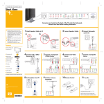
Quick
Reference
and Rack
Installation
Instructions
hp StorageWorks
NAS 9000s
Thank you for purchasing your new HP
StorageWorks NAS 9000s
1. Selecting the Optimum Environment
3. Installing Options
Select an installation site that meets the following requirements:
The NAS 9000s two-way server is housed in a modular, 4U
(7” high) rack-mount chassis that combines expandability with
efficient and space-saving design. The server combines enhanced
performance and optimal rack density with maximum availability
and manageability.
■
If you are installing additional options, such as expansion boards,
processors, PPMs, hard drives, or memory, you can refer to the
instructions included with the option purchase, the back of this
poster, or the setup and installation guide.
Important Safety Information
Before installing this product, read the Important Safety
Information document provided.
WARNING: This product contains energy levels that are
considered hazardous. To reduce the risk of personal injury
from electric shock and hazardous energy, individuals who
are knowledgeable of the procedures, precautions, and
hazards associated with equipment containing hazardous
energy circuits must perform the installation and servicing of
this product.
Space and airflow
Temperature
■ Power
■ Grounding
■
Detailed installation site requirements for this server are listed in
the setup and installation guide. For guidance in placing servers
and components into a rack, refer to the rack template or the
setup and installation guide.
2. Unpacking the Shipping Boxes
Unpack the server by following the instructions and illustrations
printed on the outside of the boxes. Also unpack the power cords,
rack mounting hardware, and the hardware documentation,
reference information, and software packs that are located in the
country kit box.
In addition to these items, you may need:
■
© Copyright 2003 Hewlett-Packard Development Company, L.P.
Hewlett-Packard Company makes no warranty of any kind with regard to
this material, including, but not limited to, the implied warranties of
merchantability and fitness for a particular purpose. Hewlett-Packard shall
not be liable for errors contained herein or for incidental or consequential
damages in connection with the furnishing, performance, or use of this
material.
This document contains proprietary information, which is protected by
copyright. No part of this document may be photocopied, reproduced,
or translated into another language without the prior written consent of
Hewlett-Packard. The information contained in this document is subject to
change without notice.
Compaq Computer Corporation is a wholly-owned subsidiary of
Hewlett-Packard Company.
Hewlett-Packard Company shall not be liable for technical or editorial
errors or omissions contained herein. The information is provided “as is”
without warranty of any kind and is subject to change without notice. The
warranties for Hewlett-Packard Company products are set forth in the
express limited warranty statements for such products. Nothing herein
should be construed as constituting an additional warranty.
Printed in the U.S.A.
WARNING: To reduce the risk of personal injury or damage
to the equipment:
■ Observe local occupational health and safety
requirements and guidelines for manual material
handling.
■ Obtain adequate assistance to lift and stabilize the chassis
during installation or removal.
■ Be aware that the product becomes unstable when it is not
fastened to the rails.
■ Before removing the server from the rack remove all
hot-plug power supplies, power modules, and drives to
reduce the overall weight of the product.
■ Before removing the server from the rack remove all
hot-plug power supplies, power modules, and drives to
reduce the overall weight of the product.
Rack Stability
WARNING: To reduce the risk of personal injury or damage
to the equipment, be sure that:
Note: For quick start memory guidelines, refer to the flowchart and
other information located on the back of this poster.
■
■
■
■
■
Torx T-15 tool, which is located on the rear of the server
Phillips screwdriver
Options to be installed, such as expansion boards, monitors,
power supplies, processors, processor power modules
(PPMs), and memory modules
Application software
Flat-blade screwdriver
Felt-tip marker or pencil
Note: Save the packing material for reuse if you need to ship the
server in the future.
Note: Protect the server from power fluctuations and temporary
interruptions with a regulating uninterruptible power supply (UPS).
This device protects the hardware from damage caused by power
surges and voltage spikes, and keeps the system in operation during a
power failure. For more information on UPS and other options, refer to
the HP website:
www.hp.com
■ The leveling jacks are fully extended to the floor.
■ The full weight of the rack rests on the leveling jacks.
■ The stabilizing feet are connected to the rack if it is a
single-rack installation.
■ The racks are coupled together in multiple-rack
installations.
■ The components are extended one at a time only. A rack
may become unstable if more than one component is
extended.
Audience Assumptions
HP StorageWorks NAS 9000s
Quick Reference and Rack Installation Instructions
First Edition(September 2003)
Part Number: 352401–001
[bar code goes here in
text box, if applicable]
352401- 001
This poster provides a quick way for customers experienced in
server installations to setup and configure the NAS 9000s server.
The following instructions are written for persons who are
qualified in installing and servicing computer equipment and are
trained in recognizing hazards in products with high-energy
levels, such as the power supplies, System Power Modules, and
redundant line cord switches in this computer system. For
detailed instructions, refer to the setup and installation guide.
See other side
Quick
Reference
and Rack
Installation
Instructions
hp StorageWorks
NAS 9000s
Thank you for purchasing your new HP
StorageWorks NAS 9000s
1. Selecting the Optimum Environment
3. Installing Options
Select an installation site that meets the following requirements:
The NAS 9000s two-way server is housed in a modular, 4U
(7” high) rack-mount chassis that combines expandability with
efficient and space-saving design. The server combines enhanced
performance and optimal rack density with maximum availability
and manageability.
■
If you are installing additional options, such as expansion boards,
processors, PPMs, hard drives, or memory, you can refer to the
instructions included with the option purchase, the back of this
poster, or the setup and installation guide.
Important Safety Information
Before installing this product, read the Important Safety
Information document provided.
WARNING: This product contains energy levels that are
considered hazardous. To reduce the risk of personal injury
from electric shock and hazardous energy, individuals who
are knowledgeable of the procedures, precautions, and
hazards associated with equipment containing hazardous
energy circuits must perform the installation and servicing of
this product.
Space and airflow
Temperature
■ Power
■ Grounding
■
Detailed installation site requirements for this server are listed in
the setup and installation guide. For guidance in placing servers
and components into a rack, refer to the rack template or the
setup and installation guide.
2. Unpacking the Shipping Boxes
Unpack the server by following the instructions and illustrations
printed on the outside of the boxes. Also unpack the power cords,
rack mounting hardware, and the hardware documentation,
reference information, and software packs that are located in the
country kit box.
In addition to these items, you may need:
■
© Copyright 2003 Hewlett-Packard Development Company, L.P.
Hewlett-Packard Company makes no warranty of any kind with regard to
this material, including, but not limited to, the implied warranties of
merchantability and fitness for a particular purpose. Hewlett-Packard shall
not be liable for errors contained herein or for incidental or consequential
damages in connection with the furnishing, performance, or use of this
material.
This document contains proprietary information, which is protected by
copyright. No part of this document may be photocopied, reproduced,
or translated into another language without the prior written consent of
Hewlett-Packard. The information contained in this document is subject to
change without notice.
Compaq Computer Corporation is a wholly-owned subsidiary of
Hewlett-Packard Company.
Hewlett-Packard Company shall not be liable for technical or editorial
errors or omissions contained herein. The information is provided “as is”
without warranty of any kind and is subject to change without notice. The
warranties for Hewlett-Packard Company products are set forth in the
express limited warranty statements for such products. Nothing herein
should be construed as constituting an additional warranty.
Printed in the U.S.A.
WARNING: To reduce the risk of personal injury or damage
to the equipment:
■ Observe local occupational health and safety
requirements and guidelines for manual material
handling.
■ Obtain adequate assistance to lift and stabilize the chassis
during installation or removal.
■ Be aware that the product becomes unstable when it is not
fastened to the rails.
■ Before removing the server from the rack remove all
hot-plug power supplies, power modules, and drives to
reduce the overall weight of the product.
■ Before removing the server from the rack remove all
hot-plug power supplies, power modules, and drives to
reduce the overall weight of the product.
Rack Stability
WARNING: To reduce the risk of personal injury or damage
to the equipment, be sure that:
■ The leveling jacks are fully extended to the floor.
■ The full weight of the rack rests on the leveling jacks.
■ The stabilizing feet are connected to the rack if it is a
single-rack installation.
■ The racks are coupled together in multiple-rack
installations.
■ The components are extended one at a time only. A rack
may become unstable if more than one component is
extended.
Audience Assumptions
HP StorageWorks NAS 9000s
Quick Reference and Rack Installation Instructions
First Edition(September 2003)
Part Number: 352401–001
[bar code goes here in
text box, if applicable]
352401- 001
This poster provides a quick way for customers experienced in
server installations to setup and configure the NAS 9000s server.
The following instructions are written for persons who are
qualified in installing and servicing computer equipment and are
trained in recognizing hazards in products with high-energy
levels, such as the power supplies, System Power Modules, and
redundant line cord switches in this computer system. For
detailed instructions, refer to the setup and installation guide.
■
■
■
■
■
Torx T-15 tool, which is located on the rear of the server
Phillips screwdriver
Options to be installed, such as expansion boards, monitors,
power supplies, processors, processor power modules
(PPMs), and memory modules
Application software
Flat-blade screwdriver
Felt-tip marker or pencil
Note: Save the packing material for reuse if you need to ship the
server in the future.
Note: Protect the server from power fluctuations and temporary
interruptions with a regulating uninterruptible power supply (UPS).
This device protects the hardware from damage caused by power
surges and voltage spikes, and keeps the system in operation during a
power failure. For more information on UPS and other options, refer to
the HP website:
www.hp.com
Note: For quick start memory guidelines, refer to the flowchart and
other information located on the back of this poster.
4. Installing the Server into a Rack
To identify the required space and location for the server with the
template:
7. Install the rails on both sides of the chassis.
10. Install the front of the rail into the designated holes in the
front of the rack.
1. Identify the front side of the template.
13. Tighten the thumbscrews to secure the server to the rack.
5. Connecting the Power Cord and Device
Cables
The NAS 9000s server can operate either on a 120-V or a 240-V
AC input. Two AC inlets are on the rear of the server, one for
each power supply installed.
2. Starting at the bottom of the rack or at the top of a previously
mounted component, secure the template against the front of
the rack by pressing the two push tabs. Match the hole pattern
on the template with the holes in the vertical rails of the rack.
2
3. Align the template so that the sides of the template are even
with the sides of the rack. Tick marks on the vertical rails of
the rack help you maintain the proper alignment.
Note: Tick marks on the rack’s vertical posts mark off U-spaces in the
rack configuration and help to maintain the proper alignment
3
1
WARNING: To reduce the risk of electric shock or damage to
the equipment:
■ Do not disable the power cord-grounding plugs. The
grounding plugs are an important safety feature.
■ Plug the power cords into grounded (earthed) electrical
outlets that are easily accessible at all times.
■ Disconnect power from the server by unplugging the
power cords from either the electrical outlets or the server.
8. Pull the rail compression lever towards you.
11. Install the rails on the chassis into the rails in the rack.
To connect the power cords:
1. Locate the correct voltage line cords that came with your
server. Remove any labels that cover the cord connectors.
2
2. Plug the power cords into the power supply AC inlets.
1
1
Note: To connect the power cords, plug them into the appropriate
power supply AC inlets. The power connector is connector number
one for the primary power supply and is connector number two for the
redundant hot-plug power supply.
2
3. Plug the other end of the power cords into grounded electrical
outlets or UPS, depending on power cord types.
Note: To help protect the server against downtime due to a loss of
power, plug each power supply into separate AC circuits.
4. Using a pencil, mark the locations on the rack where you
insert the rack rail tabs (1).
5. On the rack, mark the top and the bottom edges of the
template (2). This step helps you align a template for the next
component.
6. Move to the rear of the rack and turn the template over so you
can use the backside of the template. Repeat steps 2 through 5
on the rear of the rack.
Note: On the rear of the rack, make the pencil marks on the inside of
the vertical rails. These markings guide you in installing rack rails into
the interior of the rack frame.
9. Install the rear of the rail into the designated holes in the rear
of the rack.
12. Slide the server onto the rack rails until the locking pin
engages.
4. Connect the peripheral device cables to the server, and then
route the power cord and device cables through the cable
management solution. For more information, refer to the
Cable Management System Reel Assembly Installation
Instructions that are included in the hardware kit.
6. Powering Up the Server
Memory Configuration and Installation
Online Spare
The NAS 9000s is preloaded with the NAS OS. Prior to power
up, deployment instructions found in the Installation Guide
Guide should be followed to enable the successful configuration
of the NAS device in addition to the guidelines found below.
The NAS 9000s server ships standard with 4 GB of PC1600 DDR
Standard Memory (Advanced ECC). Additional components may
be purchased to provide varying levels of redundancy. The
sections below detail these advanced memory configurations.
■
Required Items:
1. Choosing the Memory Mode
■
■
Installation Guide
Administration Guide
To begin the first-time startup procedure:
1. Be sure that the server is safely installed in an adequate
environment.
2. Be sure that the power cables and peripheral devices are
plugged in and that adequate AC power is supplied to the
server.
■
Provides Advanced ECC protection, which protects against
single-bit errors and some multi-bit errors
■ Maximizes system memory capacity
■
■
www.register.hp.com
9. Finding Additional Information
For additional information about this server and other HP
products, refer to the HP website at
www.hp.com
Regulatory Compliance Information
The rating label on the device shows which class (A or B) the
equipment falls into. Class B devices have an FCC logo or FCC
ID on the label. Class A devices do not have an FCC ID or logo
on the label. When the class of the device is determined, refer to
the following corresponding statement. For complete regulatory
notices, see the setup and installation guide in the server
documentation.
Series Number
For the purpose of regulatory compliance certifications and
identification, your product has been assigned a unique series
number. The series number can be found on the product
nameplate label, along with all required approval markings and
information. When requesting compliance information for this
product, always refer to this series number. The series number
should not be confused with the marketing name or model
number of the product.
■
Standard Memory (Advanced ECC)
7. System Software
Register the server online at
■
■
Online Spare
8. Registering Your Server
■
Consult this overview when determining what type of memory
protection is best for your needs.
3. Refer to the Installation Guide prior to powering up the
device.
The HP StorageWorks NAS 9000s is preloaded with software
from the HP Factory and is ready to be customized for the
customer environment. For details regarding the customization of
the NAS device for the environment, please see the Installation
Guide included with the product, prior to powering on the
product.
■
Provides higher level of memory protection than standard
memory
■ Does not protect against multi-bit errors
■ Online spare bank must match the largest DIMM bank used in
the server
■ Downtime must be scheduled to replace failed memory
Single-Board Mirrored Memory
Provides a higher lever of memory protection than online
spare when using only one memory board
■ Provides protection against both single-bit and multi-bit
errors
■ Supports up to 8 GB of system memory and 8 GB of
redundant memory using 2-GB DIMMs
■ Downtime must be scheduled to replace failed memory
■
Hot-Plug Mirrored Memory
■
■
■
■
■
Provides complete redundancy by using an additional
memory board
Requires two memory boards configured identically
Provides superior memory protection against single-bit and
multi-bit errors
Provides hot-plug replacement capability
Eliminates server downtime
Install DIMMs in groups of four.
Bank A must always be populated.
All DIMMs in a bank must be identical.
System has no hot-plug capabilities in this configuration.
One or two memory boards can be configured for online
spare.
DIMMs in the online spare bank must be of equal or greater
capacity than all other banks.
Bank B on the memory board in slot 1 is the online spare
bank, even if two memory boards are installed, and must be
populated in this configuration.
Hot-Plug Mirrored Memory
■
■
■
■
■
■
Install DIMMs in groups of four.
Bank A must always be populated.
All DIMMs in a bank must be identical.
The "Ready to Hot Plug" LED indicates when a memory
board can be hot-plugged.
Two memory boards must be installed.
Both memory boards must be configured identically to enable
mirroring. Corresponding banks (for instance, bank A on the
memory board in slot 1 and bank A on the memory board in
slot 2) must be populated with DIMMs of the same capacity.
Install DIMMS in groups of four.
Bank A must always be populated.
■ All DIMMs in a bank must be identical.
■ System has no hot-plug capabilities in this configuration.
2. Select System Options.
3. Installing and Testing the DIMMs
If you plan to use online spare memory or hot-plug mirrored
memory, HP recommends testing new DIMMs.
To test DIMMs during each boot:
3. Select Advanced Memory Protection.
1. Power on the server.
2. Press the F9 key to enter RBSU.
3. Select Advanced Options.
4. Change POST Speed Up to disable.
5. Press the Esc key twice to return to the main RBSU menu.
8. Configure your memory.
■
1. Press the F9 key to enter RBSU.
Install DIMMs in groups of four.
■ Bank B mirrors bank A. Bank A must always be populated.
■ All DIMMs in a bank must be identical.
Consult the following guidelines when configuring the memory
for the server.
■
You must configure the memory in the server before deployment.
To configure memory through RBSU:
■
6. Press the F10 key to exit RBSU. The server reboots and tests
all memory in the system.
Standard Memory (Advanced ECC)
Note: To reconfigure the memory mode after initial setup, you must
reboot the system and enter RBSU.
Single-Board Mirrored Memory
2. Determining Memory
Configuration/Guidelines
Note: Memory board slot 1 must always be populated.
4. Configuring the Memory
7. Once the memory has been tested, re-enable POST Speed Up
for faster system boot.
4. Select your memory mode.
5. Press the Enter key.
6. Press the Esc key twice to return to the main RBSU menu.
Opening and Removing the Rear Access Panel
Line up guide marks on access
panel and chassis to install and
remove the panels.
1
Replacing a Redundant Hot-Plug
Power Supply
Exterior View of Server
1
1
2
2
3
4
5
6
7
8
Remove power
supply
3
4
2
Installing a SCSI Drive
Removing the Front Access Panel
Install Power Supply
2
3
1
3
5
3
5
5
2
1
3
11
3
4
Eject button for
multibay 1
Multibay 2 (DVD-ROM)
Multibay 1 (Diskette)
Eject button for
multibay 2
Front Unit Identification
LED and Switch
Internal health LED
External health LED
Power On/Standby
button and LED
Hot-plug disk
drive bays 1-4
1
1
2
2
3
3
4
6
4
4
5
6
3
5
7
7
2
6
8
2
1
5
6
10
9
10
11
12
13
14
15
16
Simplex 0
Duplex 0
1
2
3
1
0
1
21
22
Video connector
22
23
Mouse connector
23
24
Keyboard
connector
8
10
9
3
4
1
2
1 Power LED
Blinking
8
On
9
7
24 23 22 21 20 19
18 17
16 15
14
15
13
On
12
Replacing a Hot-Plug Fan
6
1
2
System Configuration
7
3
2
8
On-Line Spare
5
6
4
1
2
5
6
Online Spare Status
B
3
4
MEMORY STATUS
1
Slots 1 through 6 are
PCI-X 64-bit, 100 MHz
1 Non-hot-plug slot 1
Memory Board Status LEDs
1
Mirroring Status
Ready to Hot-Plug
Removing and Installing a
Multibay Drive
1
5i Plus Memory Module Cabling
2
3
4
5
6
7
8
Memory Board Components
10 11
9
9
2
Non-hot-plug slot 2
3
Hot-plug slot 3
4
Hot-plug slot 4
5
Hot-plug slot 5
6
Hot-plug slot 6
7
Memory board slot 2
8
Integrated Lights-Out diagnostic LEDs
9
Memory board slot 1
A
12
36
11 Fan 7
2
34
Bus
6
16 PPM 3
2
22
3
30
29
23
19 PPM 4
FRONT
20 Battery backed write cache
5
23 Fan 5
On SCSI backplane
24 SCSI port A
26 SCSI port B
27 Battery
28 Fan 3
29 Fan 1
6
30 Fan 2
31 Pass-through board connector
4
27
26
S1
32 Non-Maskable Interrupt (NMI)
switch
S2
33 Configuration Maintenance
Switch (SW4)
34 System ID Switch (SW7)
35 Integrated Lights-Out override
S3
S4
switch (SW8)
36 30-pin Remote Insight
Lights-Out Edition II Board
connector
37 PCI-X Hot Plug board
connector
* Optional on some models.
35
24
25
5
Configuration Maintenance Switch (SW4)
Switch Function (bold is default)
21 5i Plus Memory Module connector
25 SCSI Simplex/Duplex switch
5
33
enabler *
Remote Insight Management Cabling
1
21
28
18 Processor 4
22 Fan 6
19
20
Duplex
Simplex
17 Processor 3
2
18
Item
31
14 Processor 2
1
8
17
Bus
2
32
15 PPM 2
Memory error has occurred on this bank and system has failed over to
the online spare bank.
6
16
Bus
10
33
10 Fan 4
4
15
35
Reserved
Off = System configuration can
be changed
On = System configuration is
locked and cannot be
modified
Reserved
Off = Booting from floppy disk
is controlled by config
On = Booting from floppy disk
is enabled and config is
overridden
Switch Function (bold is default)
S5
S6
S7
S8
Off = Power-On password
works normally
On = Power-On password is
disabled
Off = Configuration valid
On = ROM treats system
configuration as invalid
Off = Disable
On = Enable
Off = Disable
On = Enable
6
7
8
9
10
Integrated Lights-Out Override Switch (SW8)
Position Description Indication
2
Reserved
1
iLO securtiy
override
Off = Normal (default)
On = Override
10
9
11
12
1
11
3
5
2
14
13 Processor 1
3
12
13
37
12 Processor Power Module (PPM) 1
4
Status
(Amber)
Off
No AC power
No AC power to this
On
specific power supply
Or
Power supply
failure
AC power present
Off
System in standby mode
Power supply on and
Off
working properly
Blinking Power supply current limit
exceeded
8
3
5
2 Fault LED
3
4
4
6
Power Supply LEDs
(Green)
Off
Off
12
1
7
1
11
2
9
SCSI IDs
Primary hot-plug power 17 Rear Unit
Identification
supply
LED and switch
Redundant hot-plug
power supply
17 Integrated
18
Lights-Out
AC inlet (redundant)
Network port
AC inlet (primary)
connector
18 Serial connector
19
Dual Port PCI-X 1000T
Gigabit NIC
19 USB connector 1
20
PCI-X Hot Plug
20 USB connector 2
21
slots 1, 3-6
Torx T-15 wrench (access
panel removal tool)
4
11
12
Description
7