1
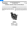
Shertech Operating Instructions, Performance,
Specifications and Parts Manual
Bronze Models GCBN2V, GGCBN3V, GCBN22V and GCBN33V
Cast Iron Models GCCV2V, GCCV3V, GCCV22V and GCCV33V
Please read and save this Repair Parts Manual. Read this manual and the General Operating Instructions carefully before attempting to assemble, install,
operate or maintain the product described. Protect yourself and others by observing all safety information. The Safety Instructions are contained in the
General Operating Instructions. Failure to comply with the safety instructions accompanying this product could result in personal injury and/or property
damage! Retain instructions for future reference.
Carbonator-Mount Rotary
Close-Coupled External Gear Pumps
Refer to form L-4082 for General Operating and Safety Instructions.
Description
Shertech self-priming, positive displacement, external rotary gear pumps are ideal for a wide range of intermittent and
light-duty industrial, marine, agricultural, and commercial applications, providing a nearly pulseless flow. Close-coupled
models are available directly mounted to NEMA framed, AC ODP single-phase, thermally overload-protected motors or as
pump heads only for custom installations. All models include a pressure relief valve. Motor-driven models are HP configured to
handle up to 500 SSU at 100 psi (specific gravity of 1.0).
Uses: For use with non-particulate and non-abrasive fluids compatible with pump wet-end construction component materials.
• Flows to 4.4 GPM.
• Max. RPM: 1725.
• Max. PSI: 100.
• Maximum viscosity of 500 SSU at 1725 RPM (max. input torque of 45 in.-lbs.).
• Pumps can operate bi-directionally (reversible). In reverse operation, the pressure relief valve will not function.
• Temperature ranges from -20° to 210° F.
• Maximum working pressure: 150 PSI.
CARBONATOR-MOUNT CAST IRON PUMPS (INTERMITTENT DUTY) – Specifically designed for use with oil-based fluids. Not
to be used with water-based fluids. Pumps include steel spur gears with steel shafts and cast iron shaft support; standard
pressure relief valves that can be ported internally or externally and a Viton mechanical carbon/ceramic-faced seal with
temperature range of 32° to 280° F. Wet-end parts are constructed from cast iron, steel, stainless steel (302, 303 and/or 18-8),
carbon, ceramic, and Viton.
CARBONATOR-MOUNT BRONZE PUMPS (INTERMITTENT DUTY) – Excellent for water-based fluids. Feature 303 stainless steel
shafts, carbon graphite bushings, and Buna-N mechanical carbon/ceramic faced seal with a temperature range of -20° to 210° F.
Standard pressure relief valves can be ported internally or externally. Wet-end parts are constructed from bronze, brass,
stainless steel (302, 303 and/or 18-8), graphite, carbon, and Buna-N.
PUMP HEADS (NO MOTOR) – Close-coupled gear pump heads are designed to direct couple to carbonator pump motors
(See NEMA Spec. MGI-18.739, Dimensions of Carbonator Motor mounting). The face of this gear pump has been machined to
match the carbonator motor face. Pump and motor held together with a stainless steel beveled “V” band clamp. Coupling of
shafts is done by mating the carbonator motor’s slot with the pump’s slot using the Oldham coupling (See Figure 2). This positive
displacement characteristic offers a wide range of applications.
NOTE: See Rotary Gear Pump Selection Guide in the Motor Manual for suggestions concerning installation, selection, options,
and accessories.
WARNING: Do not use to pump flammable or explosive fluids such as gasoline, fuel oil, kerosene, etc. Do not use in flammable
and/or explosive atmospheres. When pumping hazardous or dangerous materials, use only in room or area designated for that
purpose. For your protection, always wear proper clothing, eye protection, etc. in case of any malfunction. For proper handling techniques
and cautions, contact your chemical supplier, insurance company and local agencies (fire dept., etc.). Failure to comply with this warning
could result in personal injury and/or property damage.
Form L-4083 (1/06)
Bronze Models GCBN2V, GCBN3V, GCBN22V and GCBN33V
Cast Iron Models GCCV2V, GCCV3V, GCCV22V and GCCV33V
Shertech Operating Instructions, Performance,
Specifications and Parts Manual
Carbonator-Mount Rotary
Close-Coupled External Gear Pumps
Model Ordering Codes and Options
Example Model: GCBN33V
(1)
GC
(2)
B
(3)
N
(4)
3
(5)
3
(6)
V
1st
2nd
3rd
4th
5th
6th
Mounting
Material
Sealing
Gear Size: Ports
AC Motor
Options
N: Nitrile
(Buna-N)
2: 1/4"
1: 1/4 HP
3: 1/2"
2: 1/3 HP
GC: Gear
Carbonator
B: Brass
C: Cast Iron
V: Viton
3: 1/2 HP
V: Pressure
Relief Valve
(Standard)
If blank, motor is
not included with
pump head.
NOTE: Not all order code combinations (configurations) are standard models available from the manufacturer. Custom model
configurations may require ordering standard components and/or optional parts that will need to be assembled by the customer.
Manufacturer reserves the right to change model order codes, standard models, specifications, and performance without
notification.
Maximum motor speed is 1725 RPM.
Cast iron is not for use with water-based fluids.
Form L-4083 (1/06)
2
Shertech Operating Instructions, Performance,
Specifications and Parts Manual
Bronze Models GCBN2V, GCBN3V, GCBN22V and GCBN33V
Cast Iron Models GCCV2V, GCCV3V, GCCV22V and GCCV33V
Performance
Bronze
Models
Cast Iron Port
Models Size*
Motor
HP
RPM
Equipped
Models with Motors
GCBN22V GCCV22V
1/4
1/3
1725
GCBN33V GCCV33V
3/8
1/2
1725
Models without Motors
Suggested
GCBN2V
GCCV2V
1/4
1/3*** 1725
GCBN3V
GCCV3V
3/8
1/2*** 1725
GPM Pumping 10 Wt. Oil at 70° F (500 SSU)
Max. Input Suction Free Flow 20 PSI
40 PSI 60 PSI 80 PSI 100 PSI
Torque in.-lbs. Lift**
GPM
GPM
GPM
GPM
GPM
GPM
45
45
3.2
3.6
2.2
4.4
2.1
4.3
2.0
4.2
1.8
4
1.7
3.8
1.6
3.6
45
45
3.2
3.6
2.2
4.4
2.1
4.3
2.0
4.2
1.8
4
1.7
3.8
1.6
3.6
Test data taken on SAE 10 wt. oil at 70° F (500 SSU).
Performance in water will decrease by about 10%, and HP required will also be reduced by 10%. (Don’t use water with Cast Iron.)
Pump performance when pump is new. As pump wears, the performance will decrease.
(*) NPT inlet and outlet (in inches).
(**) Suction lift requires wetted gears and primed seal chamber.
(***) Motor not provided.
NOTES: Pumps with motors are HP rated to handle up to 500 SSU at 100 PSI and specific gravity of 1.0.
Max. PSI = 100
Max. Viscosity = 500 SSU
Max. RPM = 1725
Max. Specific Gravity = 1.1 at 100 PSI, up to 1.6 at lower PSI & viscosity.
Max. Input Torque = See chart above.
Reverse Rotation = Pumps are equipped with pressure relief valves and can be run in reverse rotation; however, pressure relief valve will not
function when pump is reversed unless pump relief valve cover is rotated 180°.
The pump relationship between volume (GPM), pressure (PSI), speed (RPM) and horsepower is shown on performance chart in Shertech Motor
Manual form L-4082. When pumping a more viscous liquid, a slower speed, a larger pipe size pump, and possibly a larger motor should be selected.
Manufacturer reserves the right to change performance without notification.
Form L-4083 (1/06)
3
Bronze Models GCBN2V, GCBN3V, GCBN22V and GCBN33V
Cast Iron Models GCCV2V, GCCV3V, GCCV22V and GCCV33V
Shertech Operating Instructions, Performance,
Specifications and Parts Manual
Carbonator-Mount Rotary
Close-Coupled External Gear Pumps
Specifications
NEMA Min
Motor Motor
AC
Thermal
Frame HP Motor Motor Motor Insulation Overload
Motor MAX
Model Required Req Voltage Amps Frame Hz Class Protection Duty Bearings RPM
Models with Motors
GCBN22V 48Y
1/3 115
6.0
ODP
GCBN33V 48Y
1/2 115/230 8.2/4.1 ODP
GCCV22V 48Y
1/3 115
6.0
ODP
GCCV33V 48Y
1/2 115/230 8.2/4.1 ODP
Models without Motors
GCBN2V* 48Y
GCBN3V* 48Y
GCCV2V* 48Y
GCCV3V* 48Y
-
60
60
60
60
A
B
A
B
Yes†
Yes†
Yes†
Yes†
-
-
-
Cont. Sleeve 1725
Cont. Ball 1725
Cont. Sleeve 1725
Cont. Ball 1725
-
-
1725
1725
1725
1725
PUMP CONSTRUCTION (Wet End)
Port
Pressure
Size Body &
Relief
O-Rings &
*** Cover Gear Shaft Bushings Valve**** Seals**
Ship
Wt.
(lbs.)
1/4
3/8
1/4
3/8
BZ
BZ
CI
CI
BZ 303 SS
BZ 303 SS
CRS CRS
CRS CRS
CG
CG
CI
CI
BR & SS
BR & SS
CRS & SS
CRS & SS
Buna Mech
Buna Mech
Viton Mech
Viton Mech
19.8
22.8
19.3
22.3
1/4
3/8
1/4
3/8
BZ
BZ
CI
CI
BZ 303 SS
BZ 303 SS
CRS CRS
CRS CRS
CG
CG
CI
CI
BR & SS
BR & SS
CRS & SS
CRS & SS
Buna Mech
Buna Mech
Viton Mech
Viton Mech
4.3
4.8
4.0
4.3
BZ = Bronze BR = Brass CG = Carbon Graphite CI = Cast Iron CRS = Cold Rolled Steel ODP = Open Drip-Proof
(*) Motor not provided.
(**) In addition to elastomer noted, mechanical seal components have carbon on ceramic faces and 18-8 SS metal components.
(***) NPT inlet and outlet (in inches).
(****) Bronze models are made of brass and/or bronze, stainless steel (302, 303 and/or 18-8). Cast Iron models are made of cast iron, cold rolled steel
and stainless steel (302, 303 and/or 18-8 SS).
(†) Thermal overload protection reset may be automatic or manual.
NOTES: 48Y motor frame also referred to as carbonator motor.
Motor base may be removable, movable or fixed.
Motor may be split-phase or capacitor start.
Motor driver subject to change without notice (refer to motor nameplate).
Manufacturer reserves the right to change specifications without notification.
Form L-4083 (1/06)
4
Shertech Operating Instructions, Performance,
Specifications and Parts Manual
Bronze Models GCBN2V, GCBN3V, GCBN22V and GCBN33V
Cast Iron Models GCCV2V, GCCV3V, GCCV22V and GCCV33V
Dimensions
Port Width
Inlet
NPT Inlet
and Outlet
Pressure
Relief Valve
(On outlet side)
Outlet
Figure 1 - Dimensions
Pump Direction
Clockwise Rotation
(When standing in front
of the pump head)
Dimensions
Model
A*
Models with Motors
GCBN22V, GCCV22V 1/4
GCBN33V, GCCV33V 3/8
Models without Motors
GCBN2V, GCCV2V
1/4
GCBN3V, GCCV3V
3/8
Dimensions (in inches)
E
F**
G**
B
C
D
129/32
21/4
27/16
27/16
3
3
69/16
7
8
89/16
129/32
21/4
-
3
3
69/16
7
-
(*) NPT inlet and outlet (in inches).
(**) This dimension may vary due to motor manufacturer’s specifications.
NOTE: Dimensions have a tolerance of (+ or -) 1/8".
Manufacturer reserves the right to change dimensions without notification.
Form L-4083 (1/06)
5
H**
I**
J**
K**
L
M
23/4
23/4
55/8
55/8
41/4
41/4
53/4
53/4
11/16
11/16
35/8
35/8
21/2
21/2
-
-
-
-
-
35/8
35/8
21/2
21/2
Bronze Models GCBN2V, GCBN3V, GCBN22V and GCBN33V
Cast Iron Models GCCV2V, GCCV3V, GCCV22V and GCCV33V
Shertech Operating Instructions, Performance,
Specifications and Parts Manual
Carbonator-Mount Rotary
Close-Coupled External Gear Pumps
Check motor.
It may be equipped
with an automatic resetting thermal
protector and may restart unexpectedly
(see specifications chart). Protector tripping
is an indication of motor overloading as a
result of operating the pump at too high a
pressure (over 100 PSI), too high of viscosity,
too high of specific gravity, excessively high
or low voltage, inadequate wiring, incorrect
motor connections, too small a motor
(sized incorrectly, not enough HP), or a
defective motor or pump.
Do not handle pump with wet hands
or when standing in water. Failure to
follow the General Safety Information
and all warnings could result in fatal
electrical shock!
“V”Band Clamp
Seal Seat Assy.
Oldham
Coupling
Pump
Shaft
Motor
Shaft
Ext.
Ret.
Ring
Hex. Head
Clamp Screw
Figure 2 - “V” Band Clamp Assembly
Assembly
(If pump and motor are
pre-assembled, skip assembly.)
1. Refer to Figures 2 and 3.
2. Remove the hex head machine
screw from the ”V“ band clamp.
3. Slide the ”V“ band clamp away
from the mating face (do not
remove from the pump).
4. Match the pump mating face and
motor mounting hub, while mating
shafts and Oldham coupling (Ref.
No. 24, Figure 7). NOTE: The small
end of coupling goes into pump.
Rotation: When looking at the motor
shaft end, proper motor pump rotation
is clockwise (CW). Flow is left to right
(See Figure 3). Reverse the flow by
rotating the pump 180˚. Standard models are equipped with pressure relief
valves. It is important that the relief
valve be on the discharge side of the
pump. NOTE: Pump can be rotated 360°.
5. Slip the ”V“ band clamp over the
pump and motor halves (See Figure
2) and tighten the hex head clamp
screw to hold the assembly together.
6. Retighten the ”V“band clamp screw
as necessary. Use thread sealant if
screw keeps coming loose.
2. Open drip-proof motors are
designed to be used in clean, dry
locations with access to an adequate
supply of cooling air.
Int. Ret. Ring
ROTATION
OUT
IN
Pressure relief valve
(on discharge side)
Figure 3 - Rotation
Installation
IMPORTANT: In any installations where
property damage and/or personal
injury can occur when the pump is
not operating due to power outages,
discharge line freezing, or any other
reason, a back-up system(s) and/or
warning system(s) should be used.
In order to safely use this product, familiarize yourself with this pump and also with
the liquid (chemical, etc.) that is going to
be pumped through the unit. This pump is
not suitable for many liquids.
1. Locate the pump as close to the
liquid source as possible, making
the suction line as short and direct
as possible.
Ambient
temperature around
motor should not exceed 104˚F (40˚C).
Form L-4083 (1/06)
6
3. For outdoor installations, the motor
must be protected by a cover that
does not block air flow to and
around the motor.
4. The motor should be securely
fastened to a rigid surface,
preferably metallic. For rigidity,
use largest bolts that will fit
through the base holes.
Do not use to
pump flammable or
explosive fluids such as gasoline, fuel oil,
kerosene, etc. Do not use in flammable
and/or explosive atmospheres. When
pumping hazardous or dangerous materials,
use only in room or area designated for
that purpose.
For your protection, always wear proper
clothing, eye protection, etc. in case of any
malfunction. For proper handling techniques
and cautions, contact your chemical supplier,
insurance company and local agencies (fire
dept., etc.). Failure to comply with this
warning could result in personal injury
and/or property damage.
PIPING
SUCTION
1. Avoid excessive lengths or number of
fittings and bends in the suction line.
2. Attach suction line to suction inlet.
3. It is recommended that same size
pipe as pump ports be used or, in
cases requiring lengthy piping, the
next larger size pipe be used.
4. If suction lift is greater than what is
indicated in the performance chart,
attach a foot valve below liquid
level at end of suction line to ensure
positive priming. Also note: If fluid
specific gravity is greater than 1.4 or
viscosity greater than 500 SSU, a
foot valve is also recommended.
5. If solid contaminates are suspected
in a liquid, place a filter in the
suction line.
Shertech Operating Instructions, Performance,
Specifications and Parts Manual
Bronze Models GCBN2V, GCBN3V, GCBN22V and GCBN33V
Cast Iron Models GCCV2V, GCCV3V, GCCV22V and GCCV33V
6. Be certain all suction piping connections are airtight.
NOTE: Assure airtight pipe connections
with the use of a pipe joint sealant.
DISCHARGE
1. Attach discharge piping to the
discharge outlet.
Support pump and
piping during assembly and after installation. Failure to do so may
cause piping to break, pump to fail, motor
bearing failures, etc. All of which can result
in property damage and/or personal injury.
NOTE: Should the pump need to be
self-draining, the pump head should be
mounted in the vertical position with
the suction port facing down. When
pumping high viscosity fluids, the
vertical position can be used with the
suction port facing up and the pump
mounted under the source. Increasing
the suction pipe size and eliminating
bends and elbows also assists in pumping high viscosity fluids. Max. viscosity is
500 SSU at 1725 RPM.
Operation
Do not run pump dry,
as permanent damage
to the pump gears, seal, and bearings will
result. Suction pressure should never be
greater than the discharge pressure.
1. All pumps must be primed before
start-up. Never operate a pump
unless it is secured to a solid
foundation.
2. Gear pumps are built to very close
tolerances and this tolerance must
not be altered. The liquids must,
therefore, be free of all abrasives.
Sand, silt, wettable powders, etc.
must be avoided.
NOTE: Cast iron pumps are for oil-based
fluids only.
3. When pumping a more viscous
(beyond 500 SSU) liquid, a slower
speed, a larger pipe size pump,
and possibly a larger motor should
be selected.
4. Recheck motor rotation. Proper
motor/pump rotation is clockwise
(CW) looking at the motor shaft
(See Figure 3).
Shutting off
discharge without
providing pressure relief can cause extreme
over-pressure which can result in pump
and/or motor failure. Do not exceed 100 PSI
pump or system pressure.
5. On all models, the pressure relief
valve is always on discharge side
(See Figure 3).
NOTE: Globe valve or other restrictive
valves should not be used as shut-off
mechanism as they are restrictive in
nature and will seriously affect pump
performance.
4. After all piping and controls (not
supplied with unit) have been
installed, unit is ready for operation.
8. The pressure relief valve can be
converted to an external relief. This
will allow the relief to dump back
to tank and allow longer periods of
relief without pump damage.
However, this is not a full-line relief
valve, and in cases where frequent
extended relief valve operation is
anticipated, a full-line size relief
valve should be piped in the discharge line and connected either
back to the tank or well downstream of the pump suction inlet.
Adjust pressure
relief valve screw
Protective
cap
NOTE: See performance chart for Max.
Torque.
2. If a shut-off valve or handgun is
required in discharge line, provide
a pressure relief valve for pump
protection.
3. Operation under shut-off discharge
conditions will overheat and
damage pump.
loosen lock nut, then turn the set
screw (Figure 4 & 7, Ref. No. 18) in
(clockwise). Turning the set screw
out (counterclockwise) will reduce
the pressure setting. When desired
pressure is achieved, tighten lock
nut and reinstall protective cap.
PRESSURE RELIEF VALVE
6. Standard model rotary gear pumps
are supplied with a built-in pressure
relief valve. The valve may be adjusted and used to set system operating
pressure, or used as a system relief
valve to prevent pump and motor
damage that can occur when discharge line is closed off. This relief
valve is not factory set. Extended
operation (over one minute) under
shut-off conditions could cause pump
to overheat, leak, and damage itself.
7. To increase the relief valve pressure
setting, remove protective cap,
Loosen
lock nut
Figure 4 - Pressure
Relief Valve Adjustment
9. To convert the relief valve to external relief, remove the 1/4 NPT pipe
plug from the pump cover (Figure 5
& 7, Ref. No. 13) and discard. This
plug is next to the relief valve. In
the bottom of the 1/4 NPT hole,
there is a second drilled and tapped
Optional
external
bypass plug
Remove and
discard plug
Figure 5 - External Bypass Installation
Form L-4083 (1/06)
7
Bronze Models GCBN2V, GCBN3V, GCBN22V and GCBN33V
Cast Iron Models GCCV2V, GCCV3V, GCCV22V and GCCV33V
Shertech Operating Instructions, Performance,
Specifications and Parts Manual
Carbonator-Mount Rotary
Close-Coupled External Gear Pumps
Operation (Continued)
hole of 1/4 size. An optional external bypass plug (Figure 5 & 7, Ref.
No. 14 included) should be inserted
in this hole and bottomed out. The
open 1/4 NPT port must now be
piped back to the tank or well
downstream of the pump suction.
10. For operation of the pump with
pressure relief valve in reverse rotation, the motor may be reversed,
allowing for reverse rotation.
Standard models are equipped with
pressure relief valves and the pump
can be run in reverse, however, the
pressure relief valve will not function. For continuous reverse rotation, the cover plate must be rotated 180˚. This is accomplished by
removing the six cover plate screws,
rotating the cover plate, and reattaching the screws. The relief valve
should now be on the opposite side.
This will allow operation of the
pump with a functioning pressure
relief valve in reverse rotation.
Maintenance
Make certain that the
power source is disconnected before attempting to service or disassemble any components! If the power disconnect is out of sight, lock it in the open position
and tag to prevent application of power.
To store the pump, place a small quantity
of light oil or some other storage preservative compatible with your application
in the pump and rotate the shaft very
slowly to work the oil throughout the
gears and the body.
DISASSEMBLY AND ASSEMBLY
GENERAL
Check the pump for proper operation
daily, weekly, monthly, etc. If anything
has changed (pump noise, motor noise,
leaks, etc.) since the pump was new, the
pump should be removed, examined and
repaired if necessary. This is a difficult
motor/pump to repair, therefore, only
qualified electricians or service technicians should attempt to repair this unit.
Improper repair and/or assembly can
cause problems with the electric motor
used with this unit. See General Safety
Information.
Retighten the ”V“ band clamp screw as
necessary. Use Loctite or similar thread
sealant if screw keeps coming loose.
Rotary gear pumps must be drained
completely if subject to freezing
temperature and should not be
operated until temperature permits.
Form L-4083 (1/06)
8
Refer to Figure 7 for parts identification
during disassembly and assembly.
[Assumes pump is separated from
motor and that Oldham coupling
(Ref. No. 24) is removed.]
1. Remove screws (Ref. No. 3) and
cover (Ref. No. 2). Refer to
INSPECTION procedures below.
2. Lift out idler shaft (Ref. No. 8).
3. Remove internal retaining ring (Ref.
No. 12) from drive end of the pump
body (Ref. No. 1) using TruArc-type
internal snap-ring pliers.
4. Carefully pry out ceramic seat (Ref.
No. 11) and then seal (parts of
seal seat assembly using a suitable
hooked tool).
Shertech Operating Instructions, Performance,
Specifications and Parts Manual
Bronze Models GCBN2V, GCBN3V, GCBN22V and GCBN33V
Cast Iron Models GCCV2V, GCCV3V, GCCV22V and GCCV33V
NOTE: If seal rubber has become bonded to the shaft, use a pliers to remove
the seal (Ref. No 10) and replace with a
new seal assembly. Refer to INSPECTION
procedures below.
5. Remove the seal assembly spring
and metal seat.
6. Remove external retaining ring (Ref.
No. 9) from the shaft (Ref. No. 5)
using external snap-ring pliers
(21⁄2” legs).
9. Assemble pump to motor. (See
Assembly 3 through 5.)
10. All pumps must be primed before
start-up and the seal chamber needs
to be filled.
Do not run pump
dry, as permanent
damage to the pump gears, seal, and
bearings will result. Suction pressure should
never be greater than the discharge pressure.
NOTE: The carbon and ceramic seal
faces spin against each other providing
for the functional seal. The seal ceramic
seat o-ring is not the functional seal,
but its purpose is to hold the seal
ceramic seat in place.
7. Remove the gear assembly and drive
shaft (Ref. No. 4 & 5).
Pump Inspection
Inspect components for signs of
excessive wear.
Excessive wear of the pump will usually
show up as degradation of performance.
This can be seen by the flow dropping
off under pressure, excessive noise
and/or excessive wear inside the pump.
Gear pump components are precision
fit. When the gears are worn, so is the
body, shafts, bushings or shaft pockets
and housing. At that point, the pump
head should be replaced.
8. Assemble the pump in reverse order
of disassembly. Tighten cover screws
(Ref. No. 3) in opposing sequence.
As the cover (Ref. No. 2) is incrementally tightened, the shaft
(Ref. No. 5) should be periodically
turned. This ensures cover-to-body
alignment and prevents binding
of shaft.
4. Install seal seat (Ref. No. 11), with
water as a lubricant, on the O-ring
with shiny white ceramic face facing
the carbon seal (Ref. No. 10) without
touching either of the seal faces.
Scratching the seal faces will cause
the seal to leak. Using anything
other than water as a lubricant,
when installing seal and seat, may
cause seal to leak.
5. Reinstall the snap ring (Ref. No. 12).
Figure 6 - Mechanical Seal Replacement
Mechanical Seal Replacement (Refer to
Figures 6 & 7 for parts identification.)
1. Remove pump from motor, if not
already done.
2. Remove snap ring (Ref. No. 12). Pry
out seal seat (Ref. No. 11). Pull
mechanical seal (Ref. No. 10) off shaft.
(See Assembly 3 through 5.)
3. Reinstall new mechanical seal (Ref.
No. 10) on drive shaft using water as
a lubricant. Do not push on carbon
face of new mechanical seal. Push
with a hallowed out wood dowel or
piece of cardboard.
Form L-4083 (1/06)
9
Relief Valve Disassembly and Assembly
(Refer to Figure 7 for parts
identification.)
1. Standard models are equipped with
a pressure relief valve. Remove the
relief valve cap (Ref. No. 15) and
O-ring (Ref. No. 19).
2. Remove the spring (Ref. No. 22)
and piston (Ref. No. 23). A worn
or broken relief valve is a sign of
excessive pump wear. The pump
head should be replaced.
3. Assemble the relief valve in reverse
order.
Bronze Models GCBN2V, GCBN3V, GCBN22V and GCBN33V
Cast Iron Models GCCV2V, GCCV3V, GCCV22V and GCCV33V
Shertech Operating Instructions, Performance,
Specifications and Parts Manual
Contact a Shertech Distributor
Distributors can be found at www.shertech.com or www.hyproindustrial.com
(The factory only sells pumps and parts to distributors.)
Please provide following information:
-Model number
-Serial number (if any)
-Part description and number
as shown in parts list
Figure 7 - Repair Parts Illustration
NOTE: Seals and the coupling components can be replaced. If the performance or
function of the pump is impaired due to wear or other causes, it is strongly advised
that the pump head be replaced. Note that seals and o-rings used in each material
type are interchangeable. The Viton components from the cast iron models can be used
in the bronze, and the Buna in the bronze models can be used in the cast iron models.
Form L-4083 (1/06)
10
Shertech Operating Instructions, Performance,
Specifications and Parts Manual
Bronze Models GCBN2V, GCBN3V, GCBN22V and GCBN33V
Cast Iron Models GCCV2V, GCCV3V, GCCV22V and GCCV33V
Repair Parts List
Ref.
No.
Description
1
2
Opt.
3
4
5
6
7
Opt.
Opt.
8
9
10 & 11
Opt.
Opt.
12
13
14
15
16
17
18
19
20
21
22
23
24
25
26
27
Opt.
Body
Cover (relief valve standard)
Plain Cover (non-relief) ***
Soc. Head Screw
Gear
Drive Shaft
Bushing
O-ring (standard)
O-ring Buna-N
O-Ring Viton
Idler Shaft
Ext. Ret. Ring
Mech. Seal & Seat Assy. (std.)
Buna Mech Seal & Seat Assy.
Viton Mech Seal & Seat Assy.
Int. Ret. Ring
Pipe Plug**
External Bypass Relief Plug*
Relief Valve Cap
Washer
Hex Nut
Set Screw - 18-8 SS
O-ring
O-ring Retainer
O-ring
Spring - 302 SS
Piston - 303 SS
Oldham Coupling
V-Band Clamp
Dowel Pin
Carbonator Motor†
Replacement Pump Head
Part No. For Model:
GCBN2V GCBN3V
NA
NA
23570S
NA
NA
NA
NA
18927
NA
19276
NA
NA
24604
NA
24608
NA
NA
NA
NA
NA
NA
NA
NA
NA
NA
NA
NA
19564
14050
NA
NA
GCBN2V
NA
NA
23570S
NA
NA
NA
NA
18927
NA
19276
NA
NA
24604
NA
24608
NA
NA
NA
NA
NA
NA
NA
NA
NA
NA
NA
NA
19564
14050
NA
NA
GCBN3V
GCCV2V
NA
NA
23574
NA
NA
NA
NA
19276
18927
NA
NA
NA
24608
24604
NA
NA
NA
NA
NA
NA
NA
NA
NA
NA
NA
NA
NA
19564
14050
NA
NA
GCCV2V
GCCV3V
NA
NA
23574
NA
NA
NA
NA
19276
18927
NA
NA
NA
24608
24604
NA
NA
NA
NA
NA
NA
NA
NA
NA
NA
NA
NA
NA
19564
14050
NA
NA
GCCV3V
GCBN22V GCBN33V GCCV22V GCCV33V Qty.
NA
NA
23570S
NA
NA
NA
NA
18927
NA
19276
NA
NA
24604
NA
24608
NA
NA
NA
NA
NA
NA
NA
NA
NA
NA
NA
NA
19564
14050
NA
24649S
GCBN2V
NA
NA
23570S
NA
NA
NA
NA
18927
NA
19276
NA
NA
24604
NA
24608
NA
NA
NA
NA
NA
NA
NA
NA
NA
NA
NA
NA
19564
14050
NA
24650S
GCBN3V
NA
NA
23574
NA
NA
NA
NA
19276
18927
NA
NA
NA
24608
24604
NA
NA
NA
NA
NA
NA
NA
NA
NA
NA
NA
NA
NA
19564
14050
NA
24649S
GCCV2V
NA
NA
23574
NA
NA
NA
NA
19276
18927
NA
NA
NA
24608
24604
NA
NA
NA
NA
NA
NA
NA
NA
NA
NA
NA
NA
NA
19564
14050
NA
24650S
GCCV3V
1
1
1
6
2
1
4
1
1
1
1
1
1
1
1
1
1
1
1
1
1
1
1
1
1
2
1
1
Mech. seal and seat sold as set only (Ref. Nos. 10 & 11) – carbon ceramic faces with18-8 SS components.
When converting to a different seal/seat material, remember to order the o-ring (Ref. No. 7) of the same material.
(*) For external relief only (not installed from manufacturer, loose in packaging)
(**) For internal relief only (standard, installed from manufacturer)
(***) Optional cover without pressure relief valve porting. Bronze covers (models with “S” suffix) come with bushings installed. Cast iron covers do not require bushings.
(†) See Specifications chart for motor specifications.
(NA) Not Available
Form L-4083 (1/06)
11
Shertech Operating Instructions, Performance,
Specifications and Parts Manual
Bronze Models GCBN2V, GCBN3V, GCBN22V and GCBN33V
Cast Iron Models GCCV2V, GGCCV3V, GCCV22V and GCCV33V
Limited Warranty on
Carbonator-Mount
Rotary Close-Coupled External Gear Pumps
Hypro warrants to the original purchaser of its products (the “Purchaser”) that such products will be free from defects in
material and workmanship under normal use for the period of six (6) months, and accessories will be free from defects in
material and workmanship under normal use for the period of ninety (90) days. Parts carry no warranty.
“Normal use” does not include use in excess of recommended maximum speeds, pressures, vacuums and temperatures, or
use requiring handling of fluids not compatible with component materials. This warranty does not cover freight damage,
freezing damage, pump or motor damage from incorrect wiring (if equipped with motor), normal wear and tear, or damage
caused by misapplication, fault, negligence, alterations, dry running pump, or repair that affects the performance or
reliability of the product.
THIS WARRANTY IS EXCLUSIVE. HYPRO MAKES NO OTHER WARRANTY, EXPRESS OR IMPLIED, INCLUDING BUT NOT LIMITED
TO ANY WARRANTY OF MERCHANTABILITY OR FITNESS FOR A PARTICULAR PURPOSE.
Hypro’s obligation under this warranty is, at Hypro’s option, to either repair or replace the product upon return of the entire
product to the Hypro factory in accordance with the return procedures set forth below. THIS IS THE EXCLUSIVE REMEDY FOR
ANY BREACH OF WARRANTY.
IN NO EVENT SHALL HYPRO BE LIABLE FOR ANY INCIDENTAL OR CONSEQUENTIAL DAMAGES OF ANY KIND, WHETHER FOR
BREACH OF ANY WARRANTY, FOR NEGLIGENCE, ON THE BASIS OF STRICT LIABILITY, OR OTHERWISE.
Only authorized distributors can return products for Warranty. Contact your distributor or visit www.shertech.com to find a
distributor for product support.
Distributors can obtain an RMA # and contact person’s name by contacting Hypro’s customer service at 800-471-0460.
Return Procedures for Distributors
All pumps or products must be flushed of any chemical (ref. OSHA Section 0910.1200 (d)(e)(f)(g)(h) and hazardous chemicals
must be labeled before being shipped* to Hypro for service or warranty consideration. Hypro reserves the right to request a
Material Safety Data sheet from the Purchaser for any pump or product Hypro deems necessary. Hypro reserves the right to
“disposition as scrap” pumps or products returned without authorization and/or which contain unknown substances, or to
charge for any and all costs incurred for chemical testing and proper disposal of components containing unknown substances.
Hypro requests this in order to protect the environment and personnel from the hazards of handling unknown substances.
Be prepared to give Hypro full details of the problem, including the following information:
1. Model number, sale record/invoice, purchase date and from whom you purchased your pump.
2. A brief description of the pump problem, including the following:
• Liquid pumped. State the pH and any non-soluble
materials, and give the generic or trade name.
• Drive type (gas engine/electric motor; direct/belt drive;
tractor PTO) and rpm of pump.
• Temperature of the liquid and ambient environment.
• Viscosity of fluid if other than water.
• Suction lift or vacuum (measured at the pump).
• Specific gravity of fluid if other than water.
• Discharge pressure.
• Elevation from the pump to the discharge point.
• Size, type, and mesh of the suction strainer.
• Size and material of suction and discharge line.
• Abrasiveness or particulate size in fluids.
Hypro may request additional information and may require a sketch to illustrate the problem. Distributors should contact the
factory to receive a return material authorization before sending the product. All pumps returned for warranty work should
be sent shipping charges prepaid to:
[RMA# and Contact Person]
HYPRO
375 Fifth Avenue NW
New Brighton, Minnesota 55112
NOTE: Hypro reserves the right to “disposition as scrap” pumps or products returned without authorization.
*Carriers, including U.S.P.S., airlines, UPS, ground freight, etc., require specific identification of any hazardous materials being shipped.
Failure to do so may result in a substantial fine and/or prison term. Check with your shipping company for specific instructions.
Form L-4083 (1/06)
Printed in USA