1
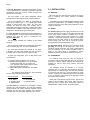
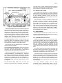
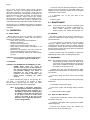
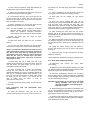
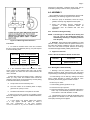
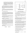
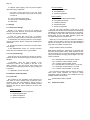
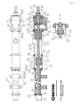
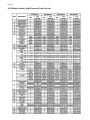
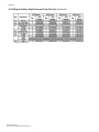
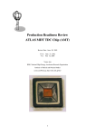
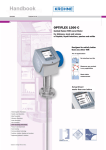
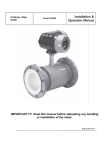
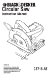
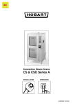
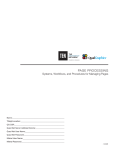
SERVICE MANUAL
MOYNO
®
Sanitary High
Pressure Pump
FRAME TYPES:
SF012, SG022, SH036, SH050
FRAME STYLE:
P1
TABLE OF CONTENTS
Page
1-1. INTRODUCTION............................................. 1
1-2. GENERAL ................................................ 1
1-3. NAMEPLATE DATA................................. 1
1-4. Pump Rotation ................................. 1
1-5. Model Number ................................. 1
1-6. Frame Designation........................... 2
1-7. Type Designation ............................. 2
1-8. Trim Code ........................................ 2
2-1. INSTALLATION .............................................. 2
2-2. GENERAL ............................................... 2
2-3. PIPING .................................................... 2
2-4. Suction Piping .................................. 2
2-5. Discharge Piping .............................. 2
2-6. FOUNDATION ........................................ 2
2-7. SHAFT ALIGNMENT .............................. 3
2.8. On Coupling Connected Units.......... 3
2.9. On Belt Drive Units........................... 3
2-10. WATER FLUSH OF SEAL ..................... 3
2-11. SHAFT BEARING .................................. 3
2-12. CLEAN-IN-PLACE OPTION................... 3
3-1. OPERATION ................................................... 4
3-2. INITIAL CHECK....................................... 4
3-3. START-UP .............................................. 4
4-1. MAINTENANCE .............................................. 4
4-2. GENERAL ............................................... 4
4-3. DISASSEMBLY ....................................... 4
4-3.1. Rotor/Stator Removal ................... 4
4-3.2. Connecting Rod and
Intermediate Drive Shaft........... 5
4-3.3. Drive Shaft and Bearings .............. 5
4-4. CLEANING ............................................... 6
4-4.1. Manual Cleaning ........................... 6
4-4.2. CIP Cleaning ................................. 6
Page
4-5. INSPECTION .............................................. 6
4-5.1. Bearings ............................................ 6
4-5.2. Drive Shaft ........................................ 6
4-5.3. 0-Rings and Seals............................. 6
4-5.4. Mechanical Seals .............................. 6
4-5.5. Pins ................................................... 6
4-5.6. Rotor ................................................. 7
4-5.7. Stator................................................. 7
4-6. ASSEMBLY ................................................. 7
4-6.1. Lubrication......................................... 7
4-6.2. Bearing/Drive Shaft ........................... 7
4-6.3. Connecting Rod and
Intermediate Drive Shaft ............... 8
4-6.4. Rotor/Stator Assembly ...................... 9
4-6.5 Stator Support/Discharge Assembly .. 9
4-6.6. Final Assembly.................................. 9
4-7. STORAGE................................................. 10
4-7.1. Short-Term Storage ........................ 10
4-7.2. Long-Term Storage......................... 10
4-8.VARIATIONS OF STANDARD PARTS....... 10
4-8.1. Trim Code ....................................... 10
4-8.2. Rotors.............................................. 10
4-8.3. Drive Shaft ...................................... 10
4-9. REPLACEMENT PARTS .......................... 10
4-9.1. Cutaway View ................................. 11
4-9.2. Parts List ......................................... 12
Section:
MOYNO® HIGH PRESSURE
SANITARY PUMPS
Page: 1
Date: June 1999
SERVICE MANUAL
®
MOYNO HIGH PRESSURE
SANITARY PUMPS
1-1. INTRODUCTION
1-2. GENERAL
The Moyno Pump is one of the most versatile pumps
available. It has been proven in thousands of applications
over the past 60 years and is backed by the experience
gained during these years, both in application and
manufacturing know-how.
The Moyno Pump is a progressing cavity pump. The
pumping action is created by the single helical rotor rotating
in the double threaded helix of the stator. As the rotor turns,
it moves eccentrically up and down. This eccentric motion
causes cavities to be created at the stator opening, at 180
degree increments. As the rotor turns, the cavities progress
in a spiral fashion along the length of the rotor from the
suction to the discharge. The interference compression fit
between the rotor and the elastomeric stator creates a
positive helical seal line. At the discharge side, the seal line
ends and the cavity is released into the discharge piping.
One cavity will diminish at exactly the same rate as the
opposing cavity increases. Thus, the sum of the two
discharges is a constant volume. The constant volume
together with the continuous spiral seat line produces a
pulseless, augered style, of positive displacement flow at
100% volumetric efficiency.
As process pressure increases, the flexible geometry of
the pump allows for multiple stages to be used. With
multiple stages, the Moyno pump can provide up to 9
positive seal lines between suction pressure and discharge
pressure. This allows the pump to develop high pressures,
with precise metering, at very low shear, and low product
degradation.
The Moyno Sanitary Pump design is built to 3A
standards. It is designed to handle a diverse array
of products from clean, light viscosity liquids to highly
viscous fluids with large particulates. Pinned drive
components provide for quick and easy disassemble.
An optional clean-in-place (CIP) capability enables
the pump to be cleaned without being disassembled.
Figure 1-1. Typical nameplate showing a rotation arrow,
model and manufacturing serial numbers.
1-3. NAMPLATE DATA
The pump nameplate, located on the bearing housing,
contains important information relating to the operation and
servicing of the pump. This information includes the
direction of rotation arrow and the pump model and serial
numbers (see Fig. 1-1).
The pump model number must be used for reference when
ordering spare parts. Please carefully file this manual for
further reference.
1-4. Pump Rotation. The direction of rotation is indicated
by a rotation arrow on the nameplate. Normal rotation of
Moyno Sanitary Pumps is clockwise when viewed from the
driven end of the pump. The elements are bi-directional, but
the seal and other components in the suction housing have
pressure limitations for reverse operation.
1-5. Model Number. The pump model number consists of three
component parts: frame designations, type designations,
and a trim code. A typical model number might be
6SF012P1 SJE SBA as shown on the nameplate in Fig. 1-1.
Page 2
1-6. Frame Designation. The frame designation consists
of 8 to 9 characters (e.g., 6SF012P1) sequenced to provide
identification of the type of frame, number of stages, and
element size of the pump.
The first number in the frame designation always
indicates the number of stages of the pumping elements.
The second character is the letter “S,” designating the
pump as the sanitary type. A “C” preceding the would
indicate a clean-in-place (CIP) option. The next letter
indicates the drive end used. The element size is
designated by the three consecutive numbers which stand
for the GPM at 100 RPM on water with no pressure. The P1
designates a standard pump type with pin joints.
1-7. Type Designation. Following the frame designation is
the type designation, a series of three letters describing the
materials from which the pump is constructed (e.g.,
6SF012P1 SSE SBA).
The first letter identifies the material of the wetted
housings.
The second letter identifies the material used in the drive
shaft, connecting rod, rotor, and other wettable parts.
The third letter identifies the material of the stator.
It identifies only the stator material and not the tube in
which the stator is placed; the tube is stainless steel.
A typical type designation, such as SSE would result
in the following:
S = Stainless steel type #304 suction housing.
S = Stainless steel type #316 or 17-4 pH internals
including drive shaft, pins, connecting rod,
rotor, and other minor metallic parts in contact
with the material being pumps.
E = Nitrile rubber stator (70 durometer, food grade
dairy).
The following letters identify the actual materials
that are used in standard construction:
FDA Food Grade:
B - EPDM
E, M - Nitrile
S - Stainless Steel
Z - Nitrile (White)
Non-Food Grade:
Q - Nitrile
F - Fluoroelastomer
R - Natural Rubber
1-8. Trim Code. Also, included in the nameplate is a threecharacter trim code designation. The first letter identifies
sealing methods, the second character identifies internal
variations and the third letter identifies rotor variations.
Consult Section 4.8 for a further explanation of trim code.
2-1. INSTALLATION
2-2. GENERAL
Moyno Pumps are lubricated and tested at the factory
prior to shipment and require minimum pre-startup
maintenance.
Accessibility to the pump and adequate clearance should
be a prime consideration in any installation. Enough space
should surround the unit so that pump maintenance can be
carried out with ease.
2-3. PIPING
2-4. Suction Piping. Suction piping should be as short as
possible. Normally, the suction line should be the same size
as the pump suction. However, conditions such as high
viscosity or required minimum flow velocities may dictate
otherwise. Long-sweep 90-degree elbows or 45-degree
elbows should be used instead of the standard elbow.
Suction piping loops which trap air should be avoided.
Piping should be pitched towards the pump.
2-5. Discharge Piping. Discharge piping diameter should
generally be as large as the pump port unless fluids
conditions indicate otherwise. The pump is disassembled
from the discharge end. An easily removable section of
piping of one stator length is suggested for simpler
disassembly without removing the pump from the base.
2-6. FOUNDATION
For maximum pump driver life, each unit should be
mounted on a strong, fabricated base which can be ordered
from Moyno. Sanitary tubular, stainless steel designs are
available as well as white epoxy painted, mild steel
baseplates.
The baseplate should be mounted on a concrete
foundation built on a solid base. The foundation should be
approximately 4” (100mm) longer and wider than the base
on which it is built (see Fig. 2-1) and should be an overall
size of 4” (100mm) to 8” (200mm) larger than the baseplate
once it is mounted. Anchor bolts for the baseplate should
be located in the foundation.
Bases with angle bracket legs should be grouted and
sealed to the foundation after anchor bolts have been
tightened evenly. Tubular Moyno bases have options of
adjustable feet, portable casters, and push handles.
Page 3
for proper tension. Tension requirements will vary with the
type of belt, center distances, and belt speeds. Consult the
belt manufacturer for specific recommendations.
2-10. WATER FLUSH OF SEAL
The standard seal arrangement is a single unbalanced
inside seal with a single coil spring. The seal is located on
the suction side of the pump which means it does not see
the high discharge pressures. Various seal faces are
available. Also available is a quench gland to provide a
water flush to the above seal.
Figure 2-1. Typical Foundation Example
Check the baseplate surface with a carpenter’s level and
place shims under the baseplate at the places necessary to
make it level. Then check the pump driver shafts and the
pump ports to ensure that they are level. Complete basemounted units supplied by Moyno, including pump driver,
are leveled with respect to the base at the factory. Shifting
may occur during shipment. The pump and driver should be
realigned. Care should be exercised to ensure that all
components are level and mounted in a direct line.
2-7. Shaft Alignment. Although the base-mounted units
supplied by Moyno are leveled with respect to the base
before shipping, most of the larger pump and driver units
are shipped with the flexible coupling disconnected.
After the base has been bolted down to the foundation,
check the following conditions:
2-8. On coupling connected units, be sure that the pump
and driver shafts are realigned before the coupling is
connected. Care should be exercised to ensure that all
components are level and mounted in a direct line.
Check the gap between coupling halves (refer to the
coupling manufacturer’s recommendations). Adjustment
can usually be accomplished by loosening the mounting
bolts on either the pump or driver and moving the loosened
component into alignment with the fixed component. On
couplings with equal diameter hubs, it may be helpful to lay
a straightedge axially across the coupling halves to check
the alignment.
2-9. On the belt drive units, check to ensure that
sheaves or sprockets are in alignment. Check belts
The water flush is used for abrasive products such
as sugar solutions, for steam barriers in aseptic
processes, and for water barriers in vacuum applications.
Clean water or low pressure steam is supplied to the
quench gland while the pump is in operation. A service
valve, strainer, solenoid, flow indicator, and flow regulator,
such as a needle valve, should be installed in the service
media line. Low pressure water (approximately I GPM) or
low pressure steam (less than 10 PSI) should be used to
prevent infiltration into the product.
2-11. SHAFT BEARING
The bearings are lubricated at the factory and will only
need to be relubricated when the shaft/bearing assembly is
completely removed from the pump.
2-12. CLEAN-IN-PLACE (CIP) OPTION
The Moyno Sanitary Pump can be customized for cleanin-place (CIP) operations. On the 012 pump, an additional
port is supplied in the extension tube for a bypass hookup.
In the 022, 036, and 050 elements, two additional bypass
ports are supplied. The bypass eliminates the flow
restriction of the pumping elements so higher CIP velocities
can be achieved in the critical suction housing and pin joint
areas.
The vacuum at the inlet of the element will naturally pull
the solution required for cleaning the rotor and stator. The
excess flow is bypassed to the discharge side while
maintaining full turbulent flow in the suction housing.
Two ports are used in the larger pumps to help divert CIP
solution to all parts of the suction housing for full coverage.
Two automatic butterfly valves or a single divert valve in the
bypass line can be used to pulse flow between the two
bypass ports. The control of the valves would be part of the
CIP program. The port on the extension tube can be rotated
for easier piping.
For fully automatic systems with no swing
connections, three closed-coupled valves (two for
the 012 element) should be installed in the bypass
Page 4
line to close off the bypass during normal pumping
operations. The valve on the discharge side should be a
divert valve, installed on a tee after the pump, with one
valve port normally open to atmosphere for drainage of the
bypass line when the valves are closed. The other valve(s)
should be a normally closed shut-off type directly
connected to the CIP ports on the suction side of the pump.
The bypass line and valves should be installed in the
horizontal position with standard pitch towards the drain valve.
See Section 4-4.2 for additional CIP reference. All valving
and bypass piping are customer-supplied unless otherwise
requested.
3-1. OPERATION
2. Once the pump has been filled with liquid, check the
direction of the pump rotation by momentarily starting and
stopping the drive. Check the rotation arrow on the pump
nameplate for correct rotation.
3. If applicable, turn on the seal water to the
quench gland.
4. Start the pump.
4-1. MAINTENANCE
Note:
In this section, the first reference to each pump part
will be followed by a number in parentheses ( ).
These numbers identify the pump parts and
hardware items in the cutaway view (Section 4-9).
3-2. INITIAL CHECK
4-2. GENERAL
Before putting the pump into operation, the following
items should be checked to ensure that each piece of
equipment is installed correctly:
-- Pump, driver, coupling or sheave alignment.
-- Electrical connections.
-- Gauges and other instruments,
-- Water flush connection (quench seal only).
-- Pump rotation (normal rotation is indicated on the
pump drive end).
-- Belt tension on belt-driven units (there should be
no appreciable deflection when first starting up)
-- Suction and discharge valves (both valves should
be open).
The Moyno Sanitary Pump has been designed for a
minimum of maintenance. Shaft bearings do not require
periodic lubrication.
CAUTION: This is a positive displacement pump.
Do not operate it against a closed valve.
4-3. DISASSEMBLY
3-3. STARTUP
CAUTION: DRY OPERATION IS HARMFUL TO THE
PUMP! Never allow the pump to
operate without liquid as dry operation
will cause premature wear of the stator
and possible damage. The stator is
lubricated by the liquid which is
pumped. Fill suction housing with
water before checking for motor
rotation.
It is good practice to periodically touch the bearing
housing to become familiar with the normal operating
temperature of the bearings. If there is a sudden, rapid rise
in temperature, remove the drive shaft and shaft bearings
from the bearing housing and either clean and relubricate
the bearings or replace them.
Inspect and either clean and relubricate or replace the
shaft bearings every 8,000 to 10,000 operating hours.
Note: The following instructions cover one procedure for
disassembling all pump components. Major pump
components can be disassembled in various ways
since specific installation limitations will determine
the method of component removal.
1. Operate pump with clean lubricating liquid or water
immediately before disassembly to ensure rotor and stator
are lubricated.
2. Shut down pump and close suction and discharge
valves.
1. Before operating the pump for the first time, fill it
with liquid.
If the liquid to be pumped is highly
viscous, dilute it before filling the pump. The liquid
fill-up will lubricate the stator for the initial startup.
3. Shut off seal water and disconnect CIP bypass piping,
if applicable.
Note: If the pump is shut down, temporarily,
enough liquid will remain in the system to
provide lubrication upon restarting. It is
advisable to maintain the suction piping
at a higher elevation than the center line
of the pump in order to contain some
liquid in the pump at the time of the
shutdown. This is especially important in
suction lift applications.
5. Disconnect suction and discharge fittings and drain
pump.
4. Electrically lock out power supply.
6. Unbolt top half of stator supports.
4-3 1. Rotor and Stator Removal
7. Disconnect the discharge reducer (23) by removing
the sanitary clamp (39).
8. If desired, unbolt stator clamp ring (34) from the stator
adapter flange (22).
9. Remove the sanitary clamp (38) between the
extension tube (21) and the stator (19).
Page 5
10. Now remove the sanitary clamp (38) between the
extension tube (21) and suction housing (20).
pin retainer (17), and snap rings (18) from the connecting
rod (13).
11. Remove the two halves of the split clamp ring (32) on
the suction housing side of this connection.
21. With a screwdriver, remove the snap ring (9) from
the pin joint connection behind the bearing housing.
12. The extension tube (21) can now be slid over the
suction housing (20) to expose the rotor side pin joint
connection. Check the two 0- rings (45) on the extension
tube and replace if necessary.
22. Slide back the pin retainer (8) and remove
the pin (7).
13. With a screwdriver, pry off the snap rings (18) and
slide back the pin retainer (17) to access the pin.
Note: The SF012 element has a single pin connection
while the SG022, SH036, and the SH050 have a
double pin connection. Disregard instructions
referencing the drive heads with the SF012 element.
14. Push out pin(s)
Replace if necessary.
(16)
and
check
for
wear.
15. Slide drive head (14) back onto the connecting
rod (13).
16. The rotor and stator assembly can now be taken
as a unit to the maintenance shop for easier disassembly.
There is a compression fit between the metal rotor and
rubber stator which must be overcome to separate the
two. This is most easily done by rotating the rotor in
relationship to the stator where the helical design will
allow the two parts to unscrew from one other.
Disassembly is much easier if the parts are still wet
with product or water.
23. From the suction housing side, pull out the
connecting rod (13) and intermediate drive shaft (12). Care
must be taken when removing the drive train. The
intermediate drive shaft fits through the brittle stationary
seat of the seal (11). The intermediate shaft should be
supported by fitting a hand through the suction inlet.
24. After removing the drive train from the suction
housing, pull off the dynamic seal face and spring (11).
Disassemble the pin joint between the two parts similar to
steps 13, 14, and 15.
25. Reach through the suction housing (20) and remove
the stationary seal face (11) from the seal housing (10).
The seal face is held in place by the compression fit of an
0-ring.
26. Unbolt the suction housing (20) and remove it.
Pull the seal housing (10) from its seat in the bearing
housing (1).
27. Inspect pin joints, O-rings, and seal faces for wear.
Replace if necessary.
This concludes the disassembly of all product contact zones.
4-3.3. Drive Shaft and Bearing Removal
17. Insert stator (19) into a sturdy vise with a rag
wrapped around the stator to protect the finish. Close the
vice and secure the stator. Make sure the stator is
adequately supported for the task.
18. Insert a breaker bar or sturdy pipe completely
through the rotor head pin hole. A bar that is the
approximate diameter of the pin is suggested. Rotate the
rotor (15) in a clockwise direction while providing a pull
force. The rotor will unscrew from the stator. Care should
be taken so the rotor head is not marred. As the
rotor is pulled from the stator, it must be
supported so it does not fall.
19. Inspect stator face, stator contour, and rotor for wear
if necessary.
4-3.2. Connecting
Shaft Removal
Rod
and
Intermediate
28. Disconnect
and coupling.
and
remove
the
pump
driver
29. Remove six hex screws (24) from bearing cover plate
(4). Slide the bearing coverplate with radial grease seal (27)
and the O-ring (44) from the drive shaft (6).
30. Pull drive shaft/bearing assembly out of bearing
housing, taking steps to support the weight of the assembly
as the bearings clear the housing. Remove grease seal
(27) from the bearing housing (1).
CAUTION: The bearings (2) are pressed on the shaft
during assembly. Care must be taken
during disassembly to avoid damaging the
bearings or shaft.
Drive
20. Slide the extension tube (21) off of the
suction housing (20) and remove the drive head (14),
31. Remove bearing set screw (28) from the bearing lock
nut (5). Using suitable spanner wrench or soft punch and
hammer, thread lock nut off drive shaft (6). Do not use a
pipe wrench to remove the lock nut.
32. Remove both halves of the bearing spacer (3) from
the shaft, and using suitable bearing press and adapters,
press bearings (2) off of the shaft.
Page 6
4-4. CLEANING AND PASSIVATION
Cleaning chemicals to be used are based upon the
product being pumped and is the responsibility of the
chemical supplier. Cleaning chemicals need to be
compatible with the elastomers used in the pump and the
chrome plating of the rotor (except for unplated rotors).
Chlorinated cleaners can pit the stainless steel housing if
allowed to dry.
In passivating the system, it is extremely important to
check with your chemical supplier that the chemicals are
compatible with the elastomer and chrome plating of the
rotor. Concentration, time of exposure, and temperature
needs to be considered. High acid solutions at elevated
temperatures will strip the chrome plating or discolor
it. The method of adding the chemicals also needs to be
considered, so there are no initial slugs of high
concentrated acids. If there is any doubt, disable the pump
drive, remove the rotor from the pump, and passivate
through the pump. Do not energize the pump during this
cycle with the rotor removed. If there is concern that the
stator will be damaged, bypass the pump completely.
4-4.1. Manual Cleaning
Disassembled parts can be cleaned by hand with the
appropriate cleaning solutions, high pressure washer,
brushes, or COP tank. Cleaning temperature is not a
concern for disassembled parts. All parts should be
inspected for cleanliness before assembling.
Caution: Care must be used in handling hot metal parts.
4-4.2 CIP Cleaning
The Moyno pump can be cleaned in place with the
optional CIP bypass port. This port allows for higher
velocity cleaning solutions to be used for downstream
equipment while maintaining the high velocity in the critical
pin joint area. It is important that the pump is operated
during CIP. The pumping element will pull whatever
solution it needs and allow the rest of the solution to be
bypassed. The wiping action of the rotor will thoroughly
clean the stator.
The eccentric motion of the rotor will cause some
turbulence in the suction housing for the pin joints. As
viscosity of the product increases, higher turbulence is
needed. Actual flow rate needed to clean the pump varies
greatly with the product being pumped, cleaning chemicals,
and temperature. Flow rates required to clean downstream
equipment is usually sufficient for light viscosity products.
Suggested cleaning temperature is 160°F or below
at the pump with a standard size (SAA trim code) rotor. The
CIP return temperature may be a better indicator of pump
temperature than the CIP supply temperature. The
elastomeric stator swells with increased temperature.
Running the pump for long periods above 160° F with a
standard size rotor will decrease the stator life. The stator
can handle higher temperatures (below 185°) for standard
length cleaning cycles. Running the pump at slower RPMs
(below 100 RPM) may be required for VFD applications.
Pulsing the pump instead of continuous running may be
required for constant speed applications. Increased starting
torque may be required over 160° F. Contact your local
representative for long cleaning cycles above 160° F or hot
water sanitizing above 180° F.
After installing the pump, the unit must be cleaned
before running product. Moyno recommends the
pump be disassembled and swabbed for the first
several cleaning cycles after running product. This
is to confirm the effectiveness of the CIP flow rates and
concentrations.
Adjust
flow
rates,
temperatures,
or concentrations if needed.
4-5. INSPECTION
4-5.1. Bearings
After cleaning, rotate bearings very slowly under hand
pressure to feel for smoothness and even action. Never
spin a dry bearing. Check for cracks, galling, pitting, burrs,
etc. Replace bearings if there is any doubt concerning
complete serviceability.
4-5.2. Drive Shaft
Inspect the drive shaft for scoring, burrs, cracks, etc.
Replace as necessary.
4-5.3. O-Rings and Seals
It is good practice to always replace grease seals
whenever the drive shaft and the bearings are removed.
4-5.4. Mechanical Seals
It is good practice to always replace the mechanical seal
whenever the pump bearing housing is disassembled.
4-5.5. Pins
Pins should be checked monthly for wear. Replace
if necessary.
Page 7
performance adequately, suspected stator wear can be
evaluated by a Moyno sales or factory representative.
4-6. ASSEMBLY
Moyno Sanitary Pumps are reassembled in reverse order
of dismantling. The following suggestions are offered:
1.
While the pump is dismantled, check all O-rings,
gaskets, and snap rings. Replace all worn parts.
2.
During the assembly process, cleanliness is
important. To avoid premature failure, all
components must be handled with care and
kept clean.
4-6.1. Lubrication During Assembly
NOTE: The bearings are lubricated at the factory and
will only need to be relubricated when the
shaft/bearing assembly is completely removed
from the pump.
Figure 4-1. Measuring Rotor Dimension
4-5.6. Rotor
1. To check for excessive wear of the rotor, measure
the rotor crest-to-crest diameter (see Fig. 4-3) and compare
it with the following chart.
Rotor Size
012
022
036,050
*Standard
Crest-To-Crest Diameter
Inches
MM
2.676
3.428
4.015
67.97
87.07
101.98
1. Bearings. Pack bearings after installation on shaft
(Section 4-6.2.). Lubricant should be packed around all of
the rollers and should completely cover the faces of the
races. The void inside the spacer between the bearings
should be filled approximately halfway with lubricant.
2.
Approved Lubricants
Caution: Do not mix different brands of lubricants.
Area to
Lubricate
Approved Lubricant
or Equivalent
Bearings
Mobilux EP2 Grease
(Mobile Chemical Co.)
*These dimensions are applicable for SAA trim codes only.
2. if the measured crest-to-crest diameter is within
0.010” (.25mm) of the standard value and is free of deep
nicks, gouges, and other and other surface defects, the
rotor is reusable.
3. Rotors with crest-to-crest values of 0.011” (.28mm) to
0.050” (1.3 mm) under the standard values should be
replaced. These rotors can be renewed by chrome plating
to standard dimensions provided that:
4-6.2. Bearing/Drive Shaft Assembly
1. Bearings must be pressed on the shaft in the
following sequence (larger units [G drive end and larger]
require heating of the bearings to 250°F before assembly).
A. Press bearing cone of shaft (6), making sure rollers
face in proper direction to receive cup (Step B). Cone
should be pressed firmly against sholder on shaft.
B. Place cup on rollers.
A.
The pin holes are not excessively worn.
B.
The rotor surface is not cracked, pitted or deeply
grooved 1/32” (.8mm) or more.
D. Place second cup on spacers.
C.
The base metal surface is not pitted or corroded.
E. Press second bearing cone on shaft with rollers facing
seat in cup. Cone should be pressed on until face of
cone is flush or even with shoulder on shaft.
C. Place bearing spacer (3) halves on cup.
4. Rotors may be sent to Moyno for replating. Rotors
should be stripped and replaced to standard dimensions,
then buffed.
5. A worn stator may appear pitted and gouged,
or it may appear smooth similar to when it
was new. Performance is the best measure
of rotor-to-stator fit. If you are unable to measure
2. Thread bearing nut (5) on shaft (6) and tighten until it
rests against the shoulder on the drive shaft. Install set
screw (28) in bearing nut and tighten.
Page 8
NOTE: The tapered bearings are designed such that
when properly installed there may be a very
slight end play in the bearings (bearing spacer
halves may slip freely out of place) or they may
have a slight pre-load (bearing spacer halves
held tightly in place and bearings do not turn
freely).
housing. When the bearing cover plate is fully secured
to the bearing housing, a small gap of 0.010 to
0.020 inch will exist between the bearing cover plate and
the bearing housing.
3. Remove bearing spacer halves (3). Thoroughly pack
lubricant around rollers and on bearing races. Install onehalf of bearing spacer. Fill area between bearings half-full
of lubricant, and install other half or bearing spacer.
7. Install the stationary seal face (11) into the seal
housing (10). Lubricate the seal O-rings. Install the seal
spring and dynamic seal face onto the intermediate drive
shaft (12).
NOTE: Assuming the bearings are not too hot, an
alternate method of lubricating bearings is as
follows: Pack the rollers of the first cone
immediately after it is pressed on shaft.
Lubricate race of first cup spacer halves in
place and fill it full of lubricant. Lubricate race
of second bearing cup and place on spacer.
Pack rollers of second cone with lubricant, and
press on shaft until flush with shoulder.
8. Set the seal housing on the ledge of the bearing
housing (1). Insert the intermediate drive shaft (12) through
stationary seal face (11) and into the drive shaft (6) at the
bearings. Care must be taken so the brittle seal faces are
not damaged.
NOTE: If too much grease is packed into the bearings
during assembly, it may seep from the grease
seals during the first few hours of operation
until the proper lubricant level is achieved.
This lubricant should be wiped from the seal
area, when the pump is not operating, to
prevent contaminants from collecting in the
seal area.
10. Rotate the seal spring so the drive tab is inserted in
the slot of the intermediate drive before it is installed. Place
bearing shaft head.
4. Install (light press) grease lip seals (27) into bearing
cover plate (4) and bearing housing (1) with Locktite. The
lip of the drive side grease seal (27) should be facing
outward with spring visible. The lip of the grease seal (27)
on the suction housing side should be facing the bearings.
the lips of both seals should be wiped with grease.
Note: The SF012 element has a single pin connection
while the SG022, SH036, and the SH050 have a double pin
connection. Disregard instructions referencing the drive
heads with the SF012 element.
5. Install drive shaft with bearings in bearing housing,
being careful to avoid damaging the first. The stationary
seat of the grease seal (27).
6. Place O-ring (44) on bearing cover plate and
bolt bearing cover plate to bearing housing using six
hex head screws (24) and lock washers. The six screws
should be tightened evenly, and care should taken to
ensure the 0-ring becomes seated in the step in the bearing
4-6.3 Connecting Rod and Intermediate
Drive Shaft Assembly
9. Secure the two shafts behind the bearings with the
drive pin (7). Insert the drive pin, slide pin retainer (8) over
pin, and lock in place with the snap ring (9).
11. Install the drive head (14) and connecting rod (13)
onto intermediate drive shaft (12). Insert
drive
pins
(16), slide on pin retainer (17), and secure with both snap
rings (18). Rotate connecting rod so the pin hole is vertical.
12. Slide seal housing gasket (31) over connecting Apply
four dabs of food grade grease to the gasket and set it in its
groove of the seal housing (10). The grease will provide
cohesion to hold the gasket in place.
13. Slide the suction housing (20) over the connecting
rod and bolt it to the bearing housing (1). Care should be
taken so the seal housing gasket does not slip out of place.
The connecting rod end may need to be temporarily
supported while installing the suction housing.
Note:
Alternatively, the seal housing, gasket and
suction housing can then be installed in
the seal housing by reaching through the
suction housing. The intermediate drive shaft,
drive head and connecting rod should be
assembled separately. The dynamic seal face
and spring can be inserted onto the
Page 9
intermediate drive shaft. The drive assembly can
then be inserted through the suction housing,
stationary seal face, and the seal housing. The
drive assembly can be supported by grabbing the
intermediate drive shaft through the suction inlet
port. Care should be taken so the brittle seal faces
are not damaged.
14. Place the snap ring (18) onto the connecting rod (13).
Install second drive head (14) onto the connecting rod.
Insert the connecting rod drive pin (16), and slide the pin
retainer (17) partially onto the drive head. The pin retainer
should cover the connecting rod pin, but leave the rotor pin
hole exposed.
15. Lubricate O-ring (45) with food grade grease and
install onto the suction housing. Slide extension tube (21)
over the suction housing (20) until it meets the suction inlet
port.
4-6.4. Rotor/Stator Assembly
Figure 4-2. Rotor Installation
There is a compression fit between the metal rotor and
rubber stator which must be overcome to insert the rotor.
This is most easily done by rotating the rotor in relationship
to the stator where the helical design will allow the rotor to
screw into the stator. Assembly is much easier if the parts
are sufficiently lubricated.
16. Insert stator (19) into a sturdy vise with a rag
wrapped around the stator to protect the finish. Close the
vice and secure the stator. Make sure the stator is
adequately supported for the task.
17. Lubricate the rotor (15) with food grade grease,
vegetable oil, or other food grade lubricant that is
compatible with the stator elastomer.
18. Insert a breaker bar or sturdy pipe completely through
the rotor head pin hole(s). A bar that is the approximate
diameter of the pin is suggested. Insert the rotor end into
the stator and push. After the rotor is 6” - 12” inside the
stator, rotate the rotor in a counterclockwise direction while
providing a push force. The rotor will screw into the stator.
The rotor will need to be supported at both ends until
enough of the rotor is inserted into the stator for the stator
to act as a support bearing. Care should be taken so the
rotor head is not marred.
19. Position the rotor in the stator, per Figure 4-2., so the
head of the rotor sticks out of the stator not less than the
length listed below:
012 = 6.40”
022 = 6.70”
036 = 7.94”
050 = 7.94”
20. If not already done so, slide clamp rings (34 and 35)
on each end of the stator. Secure both spiral retaining rings
(33) in their respective slots.
21. Install the adapter flange (22) onto the clamp ring
(34) of the suction side of the stator. Secure with lock
washer (36) and high nut (37), and hand tighten only.
22. Place rotor/stator
supports (40).
assembly
on
the
stator
23. Place the snap ring (18) onto the head of the rotor
(15). Slide the rotor into the drive head (14) and insert the
drive pin (16). Pull the pin retainer (17) over the drive head
and secure with both snap rings (18).
24. Lubricate O-ring (45) with food grade grease and
install onto the adapter flange (22).
25. Slide the extension tube (21) into position to cover
the drive head. Position the split clamp ring (32) in the
groove of the suction housing (20). Install the clamp (38) to
secure the extension tube to the suction housing.
26. Install the clamp (38) to secure the adapter flange
(22) to the extension tube (21). It may be necessary to
loosen the high nuts (37) on the ring clamp (34) so the
adapter flange is capable of being properly seated.
27. Tighten the high nuts (37) onto the adapter flange
with a wrench to pull the stator into the final position.
4-6.5. Stator Support/Discharge Assembly
28. Replace the top halves of the stator supports (40)
and bolt them to the bottom halves.
29. Install the discharge reducer (23) and secure to the
clamp ring (35) with the sanitary clamp (39).
4-6.6. Final Assembly
30. Replace driver
Check for alignment.
and
coupling,
if
applicable.
Page 10
31. Replace product piping. Cap CIP port and replace
seal water piping, if applicable.
- Internal Variations:
A - Standard Plated Shaft
B - Non-plated Shaft
X - Special to Application
Fill suction housing with liquid if the rotor stator
assembly is not lubricated or the pump will be pulling
a suction lift.
- Rotor Variations:
A - Standard Size With Chrome Plating
B - Non-plated (No Plating)
C - Standard Undersize
E - Standard Oversize
X - Special to Application
32. Connect electrical power supply.
33. Open suction and discharge valves.
34. Start pump.
4-7. Storage
4-7.1. Short-Term Storage
Storage of six months or less will not damage the
sanitary type pump. However, to ensure the best possible
protection, the following is advised:
1. Cover the pump with some type of protective
covering. Do no allow moisture to collect around the pump.
2. Disassemble the pumping elements and thoroughly
clean all components. Dry the components completely and
reassemble.
3. See drive manufacturer’s instructions for motor and/or
drive storage.
4. See OPERATION, Section 3-1. through 3-3.before
startup. Be sure all lubricants are in good condition.
4-7.2. Long-Term Storage
If the pump is to be in storage for more than six months,
perform the above short-term storage procedures plus the
following:
The trim code “SAA” identifies a pump with a single
mechanical seal. Deviations from standard are indicated by
substituting the appropriate character from the list above.
For example, the trim code “DAA” represents a pump with
double seals. The trim code “SBE” identifies a pump with
non-plated shaft and an oversized rotor.
When two or more characters are combined to identify a
variation, the three parts of the trim code are separated by
dashes. For example, the trim code “S-A-EB” identifies a
pump with a non-plated, oversized rotor.
Single mechanical seals are standard.
4-8.2. Rotors identified on parts listing are standard size
with hard chrome plated surface. Other variations of rotor
size and material may be ordered by selecting the standard
rotor part number and changing the last digits of the rotor
number as follows:
-
1. Periodically, rotate the pump manually a few
revolutions to avoid a “set” condition of the rotor in the
stator elastomer. This will prevent hard starting and
excessive torque requirements when the pump is again put
in operation.
2. If applicable, remove drive belts.
4-8. Variations of Standard Parts
4-8.1. Trim Code
Also included on the nameplate is the three-part trim
code which is used to identify pump construction. Each
character of the trim code identifies a specific aspect of
pump construction. The first character identifies sealing
variations; the second, internal variations; the third, rotor
variations.
- Sealing Variations:
D - Double Mechanical Seal (Optional)
S - Single Mechanical Seal
Q - Water Flush/Quench
X - Special to Application
015 = Standard Size, Chrome Plated, 316 SS
152 = Undersize, Chrome Plated, 316 SS
153 = Oversize, Chrome Plated, 316 SS
017 = Standard Size, Chrome Plated, 17-4 pH SS
172 = Undersize, Chrome Plated, 17-4 pH SS
173 = Oversize, Chrome Plated, 17-4 pH SS
Do not change rotor sizes without consulting your Moyno
sales office. These variations are used for certain
specialized pumping conditions only. Unplated rotors are
available. Please consult factory.
4-8.3. Standard drive shaft is unplated.
4-9.
Replacement Parts
Page 11
Page 12
4-9.2 Moyno Sanitary High Pressure Pump Part List
Moyno “Confidential”
Page 13
4-9.2 Moyno Sanitary High Pressure Pump Part List (continued)
Moyno “Confidential”
© 1999 by Moyno, Inc.
® Moyno is a registered trademark of Moyno, Inc.