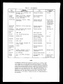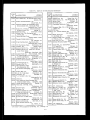
1
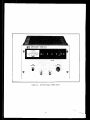
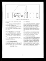
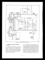
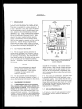
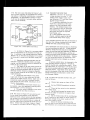
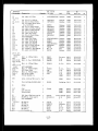
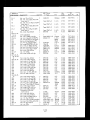
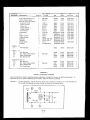
DC POWER SUPPLY
STB SERIES. MODEL
6llOA
Printed: May, 1967
@ Stock Number: 06110-90001
COPYRIGHT AND DISCLAIMER NOTICE
Copyright - Agilent Technologies, Inc. Reproduced with the permission of Agilent
Technologies Inc. Agilent Technologies, Inc. makes no warranty of any kind with regard
to this material including, but not limited to, the implied warranties of merchantability
and fitness for a particular purpose. Agilent Technologies, Inc. is not liable for errors
contained herein or for incidental or consequential damages in connection with the
furnishing, performance, or use of this material or data.
MANUAL
Model
Manual
SERIAL
Prefix
6~
6E
ALL
6E
6E
6E
II45A
1145A
1723A
183lA
0213
0513
6lIOA
DC Power Supply
HP Pati No. 06110-90001
No.
MAKE
CHANGES
Number
- 0512
- 0667
1
1,s
Errata
1.2,3
ls2j3.4
1 thru
1 thru
I thru
1 thru
I. thl
0668 - Q7,17
0718 - 0742
0743 - 0842
0843 - 0932
0933 --1447
I448 - 1507
1508
. LID
CHANGE
CHANGE
1901-0327,
RS 6.
Change
CR29 and CR30 to: Rect. Si. 75OmA
8OOpw.
quantity
2, IN5062,
GE 03508,
HP Part
No. 1901-0330,
RS 2.
CHANGE
3:
In the Replaceable
Parts Table,
change
the HP
Part No. of switch
Sl to 3lOI-1244,
This
witch
requires
new front panel lettering.
5
6
7
8
9
CHANGE
4:
In the replaceable
parts table,
No. of switch
Sl to 3lOI-1248.
1:
In tho Replaceable
Parts Table,
change
8.2Kn to 4.3L,
G%,
$W, HP Part No.
A. B. 01121.
CHANGES
R76 from
0686-4325.
change
the
HP l’art
In the Replaceable
Puts Table,
deleta
the listing
for BNC-H!l
Cable Plug and associated
hardware
and add new listing:
BNC-Z-IV Connector,
HP Part No. 1250-1267.
ERRATA:
2;
In Replaceable
Parts List,
make the following
changes:
Cl9:
Change
to HP Part No. 0180-2256.
X201 thru R209:
Change
to lL,
+l%,
+W, HP
Part No. 0811-2770.
P.G. Board:
Change
to HP Part No. 06110-60005.
Rl9:
Change
to IKn, &l%, +W, HP Part No.
0811-2770.
T2: Change
to HP Pz,rt No. 5080-7129.
Option
OS: T2: Delete.
(Transformer
need not be
changed.)
Option
18: T2: change
to HP Part No. 5080-7130.
In Table
~omtnon
5-2,
Step
connection
5 (Page S-9).
change
to “Vl72 anode.”
the
Meter
In the Replaceable
Parts Table,
add the following:
Over, heating
element,
HP Part No* 8110-0159.
(Installation
and calibration
instructions
for
oven are covered
in Service
Note P-5060-6125.)
ERRATA:
In Table
l-l
and page 5-5, paragraph
5-31,
c., change the ripple
and noise specification
“Less than 2mVrms and 5mV p-p. ”
step
to:
ERRATA:
QT. 8: Change
to 2N2907As
Sp:ague,
Part No. 1853-0099.
SS PNP Si.
In Replaceable
change:
QIl:
Change
1854-0311.
Puts
TabIe,
tQ 2N4240,
make
RCA,
56289,
change
CHANGE
The Serial Prefix of this
lI45A.
This i3 the only
the followinq
HP Part No.
On Page 6-8,
under Manual
Backdating
change
the second
wntence
to read:
To adapt the manual
to se&l
numbers
6FOl61,
make the following
changes.
On the Schematic
Diagram.
Cl4 to 2OpF.
EP
unit has been
change.
CHANGE
Changes,
prior
to
the value
of
capacitor
In the Replaceable
Parts Table,
make the following
changes:
Change
CRll,
24-28,
and 32 to: Rect. Si. 750mA
2OOprv, quantity
7, IN5059,
GE 03508,
HP Part
6:
In the Replaceable
Parts Table
change
R9 to 120.&5%,
1,‘2W,
1215.
changed
to
?!
and on the schematic,
HP Part No. 0686-
The etandwd
colors for this instrument
We now
mint gray (for fron’c and rear panels)
end olive grey
(for ell top, bottom,
side,
end other external
curOption
X95 de3ignatee
use of the former
frmd.
color scheme of light gray end blue gray.
Option
A8S designates
use of a light gray front panel with
olive gray used for 811 other external
swfaoee.
NEW pert numbers
are shown below:
,HP PART NO+
DESCRIPTION
STANDARD
OPTION
Panel
Side
Chaesis,
Right
5OSO-7950
-
Side
Chassis,
Left
5060-7949
.-
Rear
Chassis
- ass'y
5000-3482
A
5000-9421
q-
(2)
OPTION
x95
06110-00001
l?rord
cover,
A85
06lU-00002
.,
1
SM
MatItle
Pa-c6
List
1
ERRATA:
Make the following
changes
to the parts list or,
page 6-8:
Option
05: Delete
Tl (Transformer
need not
be changed).
Optlor,
18: Add R55, 12OK 5% I/UN,
06861245.
OptLone
05 and, 18:. Add R55, game 83, Option
18 above;
change
HP Part No. of T2 to 5080"
7130,
Change
part number of rubber bumper
from
0403-0088
Co 0403-0002.
On pago 6-5 and on the schematic,
change
C2Y
and C28 to lpp 2000~ HP pati No. 0160-4121.
Add to the puts
llet
fx Uluminated
swl,tch
used tn th?se suppl!es
The HP Part NT. ?f the
0244,
the replacement
lamp
3lWL248,
whtch 1s
that ~,nclude Change
4.
type AIH lamp 1,s 2l40 -
Add tq the parts IIst the mating
plugs for the
front panel output
connectors.
They we type
BNC-HV
mele coaxtal
plugs,
HP Part No. 1250 0927, Two are prwtded,
Effecttve
January
1, 1977, Options
005 (5OW eo
ibput) and 018 (230 vet Input) ere no longer aval1 able separately
as standard
opttons
for thts model
These two opti,ons heve been replaced
bye new
standard
qptton,
Optton
013, which cDmbf,nes
the
mcxdlftcattgns
of Optlone
005 and 018 f?r use with
a 230 Vac+lO%,
50&O. 3Hz !,rqut.
After ,anuery
I,
Model
6llOA Instruments
for use wtth a 115Vac
5OHz ,,nput w a 23fJVec bOHz lr,put must be ?rdered
as s~edel
fectxy
m~diflcet!raw
Make the net eseery
correoti,qns
wherever
Optl?n
005 qr 018 !,s
mentioned
f,n the manual,
The blue gray meter bezel
a black one, HP Part N?
CHANGE
has been replaced
4040 -4414.
by
8:
Make the follwtng
changes
to the schemattc
and the parts Ilet; change
R71 !I? the overvoltage
protwttm
ctroult
to 2Ok, lO%, HP Part No.
2100-0558;
chenge R25 and R67 in the meter
clrcuIt
t? lOOk, IO%, RP Pert Ng, 2100-3214.
, CFlANGE
9:
Change
power transformer
Tl to HP Part Nq,
5080 -1910, The primary
gf the netv transformer
oan be strapped
for 115vac or 23DVac input as
shown below.
Change
reer chassts
to HP Pert
No. 5000 -.3148. Replace
oapacl,tor
clamp HP
Pert No, 5000 -6023 Wth capeclt?r
bracket
F?P
part ~3. 1210-0006~
Change
zener dtgde VRZ tq 9V, 0, 005% ‘.C C,, HP
Part No. 1302 - 0785, ,Nqte that the old zener
diode (1902 ..0763) Should not be used for a
replacement
at a*y ttme,
TABLE
section
I GENEML
INFORMATION
.
.
l-l
Description
l-4
Overload
ProtectIon
l-7
cooling
l-9
Output
Terminals
l-11
Specifications
l-13
Ootions
A&essories
I-15
l-17
Instrument
Identification
l-20
Ordering
Additional
Manuals
I I INSTALIATION
.
.
.
Z.-l
InitiaL
1nspemion
z-3
Mechanical
Check
2-S
Electrical
Check
z-7
In~tellation
Data
2-9
Location
Z-11
Rack Mounting
2-15
Input Power Requirwnents
Z-17
Power Cable
2-20
Repackaging
for Shipment
I I r OPERATING
INSTRUCTIONS.
3-,
nlm-0”
Cklcxk out Prooedure
3-3
opetat1otl
3-5
Currant
Limit Provisions
3-7
Operation
of Supply
Beyond
Rated Output
3-9
Load Connection
3-13
output
capacitance
3-15
Revwse
Current
Loading
3-17
Reverse
voltage
Loarang
.
OF
CONTENTS
SeGtiOl7
IV PRINCIPLES
OF OPEPATION
4-29
Protection
Circuit
4-3 1 ovw
Control
Circuit
4-33
Reference
Clrouit
4-37
M,e’cer Circuit
Page NQ.
.1-l
l-l
l-l
l-l
l-l
l-l
l-l
l-l
1-z
l-2
Page No(ContWued)
4-5
4-5
4-5
4-6
V MAINTENANCE..
. . . . . . . . . . , . . . ,.5-l
5-l
Introduction
5-l
5-3
High Voltage
Precautions
5-l
5-6
Measurement
Techniques
5-l
5-9
Test Equipment
Required
5-l
5-11
P&ormanc~
Test
5-3
5-14
Rated Output,
Meter,
and Output
Controls
Acouracy
5-3
S-17
Load Regulation
5-3
s-13
Line Regulation
5-4
5-z 1 Ripple and Noise
5-4
s-35
Ti-ansiwlt
Recow?~
Tims
5-6
5-39
Output
Impedance
5-7
5-42
Temperature
Goefficient
5-a
5-46
Output StabMty
5-8
5-49
cument
um1t
5-9
5-51
Troubleshooting
5-9
r +?
a-32
Overall
Troubleshooting
FYoceduw
s-9
5-59
Repair and Replacement
S-15
5-61
Adjustment
and Calibration
5-17
5-63
Output
Voltage
Zero and Tracking
5-17
S-65
Meter Mechanical
Zero
5-17
5-67
Voltmeter
Tmcking
5-17
5-63
Ammeter Zero
S-17
5-71
Ammeter Ttacking
5-17
5-73
Overvoltage
Protection
5-17
5-Y 5 Oven Control
Circuit
5-18
5-18
5-77
Current
Limit Adjustment
.2-l
Z-1
2-l
2-l
2-l
2-l
Z-l
2-2
2-2
2-z
.3-l
3-l
3-l
3-l
3-l
3-l
3-2
3-2
3-2
IV PRINCrPLES
OF OPERATION
...
. . . . . 4-l
4-l
Overall
Block Diagrem
Di~cusslon
4-2
4-8
Simplified
Schematic
Discussion
4-3
4-12
Detailed
Glrcuit
Analysis
4-4
4-13
Series Regulator
4-4
4-15
Constant
Voltage
Input Circuit
4-4
4-21
Driver
and Error Amplifier
4-4
4-23
Current
Limit Circuit
4-4
4-25
High Voltage
Control
and
Doubler
Circuits
4-4
VI
ii
REPLACEAELE
PARTS.. . . . . . .
6-l
lntroduotion
6-4
Ordering
Information
Reference
Designators
Abbreviations
Menufaoturers
6-8
Code List of Manufacturers
Parts List Table
.. .
, ,6-l
6-l
6-l
6-2
6-5
TABLE
OF CONTENTS
LIST
Table
I-l
5-l
5-2
5-3
5-4
FIgme
s-2
OF TABLES
Specifications..
Test Equipment.,
*.
Bias, Reference,
and Rectifier
Voltages..
Low Output
Voltage
TroubleshootirQ..
High Output Voltage
Troubleshooting
LIST
1-l
2-l
2-2
3-l
4-l
4-2
5-l
(CONTINUED)
DC Power Supply
Rack Mwnting,
Two Units
Rack Mounti!?g,
01’1e Unit
Fwnt Panel Controls
and Indicators
Ova-all
Block Diagram
Simplified
Schematic
Diagram
High Voltage
and Troubleshooting
hC.diQ~
Diagram
Diffwatial
Voltmeter
Substitute,
Test setup
.
Page No.
l-3
5-2
5-9
~.
5-12
,
j-14
OF ILLUSTRAT!ONS
Page No.
iv
2-l
2-2
3-l
4-l
4-3
5-l
Figure
s-3
5-4
5-5
5-6
5-7
5-E
5-9
5-10
5-3
5-11
LinEand
LoadRegulatiw,
Tm5t S&up
Ripple and Noise,
Test Setup
High Voltage
Protection
Network
Noise Spikes,
Test Setup
Transient
Recovery
Time, Test Setup
Transient
Recovery
Time Wavefarns
Output
Imwdamx,
Test Setup
Printed
Circuit
Board Location
Diagram
Servicing
Printed
Wiring
Boards
Page NO.
5-3
5-4
5-5
5-6
5-7
5-7
5-7
5-10
5-16
Figure
I
l-l.
DC Power
Supply,
Model
1”
6llOA
“‘.-I
1-l
DESCRIPTION
l-10 Output power is available vie ,mo WG-931/U
connectors mounted on the front panel of the supply, Mating
cornwctors (UC=-932/U) are supplied
with the unit. The output terminals are isolated
from the chassis and either the positive or the negative terminal tnay be connected to the chassis by
shorting the cer~ter ptn tQ the case of the epplica<
ble VG-931/U connector,
or by grounding e wire
from the connector to the chassis,
The p0Wer *UPply is insulated to permit operation up to 1,000
volts dc off ground, i. e. the maximum potential
between either output terminal end ground shall not
exceed 4KVdc,
l-2
This instrument (Figure 1-l) is an all semiconductor high voltage supply suitable for either
bench or relay rack opwation.
It is a compact,
well-regulated,
Constant Voltage/Current
Limited
supply that will furnish 3, 000 volts et 6 m~lliampS
or carp be adjustEd throughout the output voltage
range, It is designed for *ppIicattons
rwuiring
extreme EtabilIty,
regulation,
and insensitivity
to
ambient temperature variations.
l-3
This supply utilizes a series regulated
“piggy-back”
circuit technique.that
consists of
placing e well-regulated
low voltage power supply
in series with e lees well-regulated
supply having
a greeter vo!tage capa.bility.
The well-regulated
“piggy-back”
supply continuously
com!x”setee
for
any ripple, load regulation,
or Iine regulation deficiencies
of the main power source end adjusts
the voltage across its series regulator so that the
total output voltage remains constant despite disturbances in the main voltage source.
l-4
l-11
l,-12 Detailed specificatlone
are. given tn Table 1-l.
l-13
for the Pow”
SUPPlY
OPTIONS
l-14 Options are factory modifications
of a standard instrument that are requested by the customer,
The following options are available for the instrum
mmt covered by this manual.
Where necessary.
detaIled option information
(operation,
alignment,
etc.) is included throughout the manual,
OVERLOAD PROTECTION
1-S The voltage thumbwheel witches
select the
constant voltage level: an internal potentiometer
selecte the current limit level.
The supply
will
automatically
crossover frbm conetant voltage to
currant limit operatim and vice versa if the output
current or voltage exceeds these preset levels.
Detailed characteristics
of the output current iimittng are given in Paragraph 3-5.
Option No*
l-6
The powor supply is protected from .+everse
voltage (positive voltage applied to negative terminal) by en internal protection diode thet shunts
current across the output terminal6 when this condition exists, clamping tha reveree voltage.
Protection from rewrse current (current forced into
the power $upply in the direction oppoiite to the
output current) must be provided by prebading
the
power supply (Paragraph 3-151, The power euppIy
cannot accept reverse current without damage.
l-7
SPECIFICATIONS
Wescription
05
5OHz Inwt Modification,
Factory
modification
includes the substitution
of 60&z with SOHz magnetic component as indicated at the end of the
perte 1Ist in Section VI. In addition,
the overvoltage
ProtectIon adjustment
is rechecked, refer to Section V.
18
23OVac +lO%, Sinqle-Phase Xnput.
Factwy modiftcation
includes the installation of a 230 volt input transformer to replace the standard 115 volt
transformers es indicated at the reer
of the parts list in Section VI.
COOLlNG
l-15
ACCESSORIES
l-16
may
1-l
be
The accessories
listed in the following chart
ordered wtth the power supply or SePeretel~
@ Part NO,
14515A
145 25A
l-1Y
nescriptim
Rack Kit for Mounting one 54” H
supply in a standard 19” EIA rack.
(Refer to Section II for details. )
Rack Kit for mounting two 5+” H
supplies in a standard 19” EIA rack.
(Refer to Section II for details. )
INSTRUMENT IDENTIFICATION
l-18 Hewtett-Packard
power supplies are icientified by a three-part
serial number tai.
The first
part is the power suwly model number.
The setand part i3 the swial’number
prefix, which consists
of a number-letter
combination that denotes the
date of a significant
de&vi change.
The number
respectively.
The third part is the
serial number: a different sequential
signed TV each power supply.
supply
number is as-
power
l-19 If the serial number prefix
on your
power
supply does not agree with the prefix on the title
page of this manual, use the change page that is
included to update the manual to the proper
serial
number. Where applicable,
backdating tnformation
is given in an appendix at,the rear of the manual.
l-20
ORDERING ADDITIONAL
MANUALS
l-21 One manual is shipped with each power supply. Additional manuals may be purchased from
your local @ sales office (see list at i-ear of this
manual for addresses).
Specify the model number,
serial number prefix, and @ St&k number provided
on the title page,