1
HP StorageWorks
N1200-320 4Gb Network Storage Router
user and service guide
*AG314-96001*
AG314-96001
Part number: AG314-96001
First edition: June 2006
Legal and notice information
© Copyright 2006 Hewlett-Packard Development Company, L.P.
Hewlett-Packard Company makes no warranty of any kind with regard to this material, including, but not limited to, the implied warranties of
merchantability and fitness for a particular purpose. Hewlett-Packard shall not be liable for errors contained herein or for incidental or
consequential damages in connection with the furnishing, performance, or use of this material.
This document contains proprietary information, which is protected by copyright. No part of this document may be photocopied, reproduced, or
translated into another language without the prior written consent of Hewlett-Packard. The information is provided “as is” without warranty of any
kind and is subject to change without notice. The only warranties for HP products and services are set forth in the express warranty statements
accompanying such products and services. Nothing herein should be construed as constituting an additional warranty. HP shall not be liable for
technical or editorial errors or omissions contained herein.
Adobe® and Acrobat® are trademarks of Adobe Systems Incorporated.
Intel and Itanium are trademarks or registered trademarks of Intel Corporation or its subsidiaries in the United States and other countries.
Microsoft, Windows, Windows NT, and Windows XP are U.S. registered trademarks of Microsoft Corporation.
Oracle® is a registered U.S. trademark of Oracle Corporation, Redwood City, California.
UNIX® is a registered trademark of The Open Group.
N1200-320 4Gb Network Storage Router user and service guide
Contents
About this guide . . . . . . . . . . . . . . . . . . . . . . . . . . . . . . . . . . . . . . . . . . . . . . . . . . . . . . . 7
Intended audience . . . . . . . . . . . . . . . . . . . . . . . . . . . . . . . . . . . . . . . . . . . . . . . . . . . . . . . . . . .
Related documentation . . . . . . . . . . . . . . . . . . . . . . . . . . . . . . . . . . . . . . . . . . . . . . . . . . . . . . . .
Document conventions and symbols . . . . . . . . . . . . . . . . . . . . . . . . . . . . . . . . . . . . . . . . . . . . . . .
HP technical support . . . . . . . . . . . . . . . . . . . . . . . . . . . . . . . . . . . . . . . . . . . . . . . . . . . . . . . . . .
HP-authorized reseller. . . . . . . . . . . . . . . . . . . . . . . . . . . . . . . . . . . . . . . . . . . . . . . . . . . . . . .
Helpful web sites . . . . . . . . . . . . . . . . . . . . . . . . . . . . . . . . . . . . . . . . . . . . . . . . . . . . . . . . . .
....
....
....
....
....
....
7
7
7
8
8
8
1 Introduction . . . . . . . . . . . . . . . . . . . . . . . . . . . . . . . . . . . . . . . . . . . . . . . . . . . . . . . . 9
External features overview . . . . . . . . . . . . . . . . . . . . . . . . . . . . . . . . . . . . . . . . . . . . .
Operation indicators . . . . . . . . . . . . . . . . . . . . . . . . . . . . . . . . . . . . . . . . . . . . . . . . .
How the HP N1200-320 4Gb Network Storage Router works . . . . . . . . . . . . . . . . . . . .
Processing SCSI information. . . . . . . . . . . . . . . . . . . . . . . . . . . . . . . . . . . . . . . . . . . .
HP N1200-320 4Gb Network Storage Router features . . . . . . . . . . . . . . . . . . . . . . . . .
Fibre Channel features . . . . . . . . . . . . . . . . . . . . . . . . . . . . . . . . . . . . . . . . . . . . .
SCSI bus features. . . . . . . . . . . . . . . . . . . . . . . . . . . . . . . . . . . . . . . . . . . . . . . . .
Management features. . . . . . . . . . . . . . . . . . . . . . . . . . . . . . . . . . . . . . . . . . . . . .
External indicators . . . . . . . . . . . . . . . . . . . . . . . . . . . . . . . . . . . . . . . . . . . . . . . .
HP N1200-320 4Gb Network Storage Router benefits . . . . . . . . . . . . . . . . . . . . . . . . .
Operating and Non-operating environments . . . . . . . . . . . . . . . . . . . . . . . . . . . . . . . .
Operating environment. . . . . . . . . . . . . . . . . . . . . . . . . . . . . . . . . . . . . . . . . . . . .
Non-operating environment. . . . . . . . . . . . . . . . . . . . . . . . . . . . . . . . . . . . . . . . . .
...
...
...
...
...
...
...
...
...
...
...
...
...
...
...
...
...
...
...
...
...
...
...
...
...
...
...
...
...
...
...
...
...
...
...
...
...
...
...
...
...
...
...
...
...
...
...
...
...
...
...
...
. 9
10
11
11
11
11
11
11
12
12
12
12
12
2 Installation, cabling, and setup. . . . . . . . . . . . . . . . . . . . . . . . . . . . . . . . . . . . . . . . . . 13
Identifying product components . . . . . . . . . . . . . . . . . . . . . . . . . . . . . . . . . . . . . . . . . . . . . . . . . . . . .
Typical installation configuration tasks. . . . . . . . . . . . . . . . . . . . . . . . . . . . . . . . . . . . . . . . . . . . . . . . .
Installing the HP N1200-320 4Gb Network Storage Router . . . . . . . . . . . . . . . . . . . . . . . . . . . . . . . . . .
Desktop installation . . . . . . . . . . . . . . . . . . . . . . . . . . . . . . . . . . . . . . . . . . . . . . . . . . . . . . . . . . .
Rack mount installation . . . . . . . . . . . . . . . . . . . . . . . . . . . . . . . . . . . . . . . . . . . . . . . . . . . . . . . . .
Separate the rack mount rails . . . . . . . . . . . . . . . . . . . . . . . . . . . . . . . . . . . . . . . . . . . . . . . . . .
Attach the outer rail assembly to the rack . . . . . . . . . . . . . . . . . . . . . . . . . . . . . . . . . . . . . . . . . .
Attach the rear extension bracket . . . . . . . . . . . . . . . . . . . . . . . . . . . . . . . . . . . . . . . . . . . . . . .
Attach the rails to the network storage router . . . . . . . . . . . . . . . . . . . . . . . . . . . . . . . . . . . . . . .
Install the router into the rack . . . . . . . . . . . . . . . . . . . . . . . . . . . . . . . . . . . . . . . . . . . . . . . . . .
Connect the power cord . . . . . . . . . . . . . . . . . . . . . . . . . . . . . . . . . . . . . . . . . . . . . . . . . . . . .
Setting up serial port communications . . . . . . . . . . . . . . . . . . . . . . . . . . . . . . . . . . . . . . . . . . . . . . . . .
Cabling the N1200-320 4Gb Network Storage Router . . . . . . . . . . . . . . . . . . . . . . . . . . . . . . . . . . . . .
Interfaces and connections . . . . . . . . . . . . . . . . . . . . . . . . . . . . . . . . . . . . . . . . . . . . . . . . . . . . . .
Fibre Channel connections . . . . . . . . . . . . . . . . . . . . . . . . . . . . . . . . . . . . . . . . . . . . . . . . . . . .
SCSI connection . . . . . . . . . . . . . . . . . . . . . . . . . . . . . . . . . . . . . . . . . . . . . . . . . . . . . . . . . . .
Ethernet connection . . . . . . . . . . . . . . . . . . . . . . . . . . . . . . . . . . . . . . . . . . . . . . . . . . . . . . . . .
Serial port connection . . . . . . . . . . . . . . . . . . . . . . . . . . . . . . . . . . . . . . . . . . . . . . . . . . . . . . .
Autobaud feature . . . . . . . . . . . . . . . . . . . . . . . . . . . . . . . . . . . . . . . . . . . . . . . . . . . . . . . .
13
13
13
14
14
14
15
16
16
17
17
18
19
19
19
20
20
21
21
3 Device management . . . . . . . . . . . . . . . . . . . . . . . . . . . . . . . . . . . . . . . . . . . . . . . . . 23
SCSI bus configuration . . . . . . . . . . . . . . . . . . . . . . . . . . . . . . . . . . . . . . . . . . . . . . . . . . . . . . . .
FC port configuration . . . . . . . . . . . . . . . . . . . . . . . . . . . . . . . . . . . . . . . . . . . . . . . . . . . . . . . . .
FC arbitrated loop addressing . . . . . . . . . . . . . . . . . . . . . . . . . . . . . . . . . . . . . . . . . . . . . . . . . . .
Soft addressing . . . . . . . . . . . . . . . . . . . . . . . . . . . . . . . . . . . . . . . . . . . . . . . . . . . . . . . . . . .
Hard addressing . . . . . . . . . . . . . . . . . . . . . . . . . . . . . . . . . . . . . . . . . . . . . . . . . . . . . . . . . .
FC switched fabric addressing . . . . . . . . . . . . . . . . . . . . . . . . . . . . . . . . . . . . . . . . . . . . . . . . . . .
Discovery . . . . . . . . . . . . . . . . . . . . . . . . . . . . . . . . . . . . . . . . . . . . . . . . . . . . . . . . . . . . . . . . .
Host bus adapter configuration . . . . . . . . . . . . . . . . . . . . . . . . . . . . . . . . . . . . . . . . . . . . . . . . . .
Logical unit management . . . . . . . . . . . . . . . . . . . . . . . . . . . . . . . . . . . . . . . . . . . . . . . . . . . . . . .
...
...
...
...
...
...
...
...
...
N1200-320 4Gb Network Storage Router user and service guide
23
23
23
23
23
23
24
24
24
3
4 N1200-320 4Gb Network Storage Router management . . . . . . . . . . . . . . . . . . . . . . . 27
Configuration methods . . . . . . . . . . . . . . . . . . . . . . . . . . . . . . . . . . . . . . . . . . . . . . . . . . . . .
Serial port management access . . . . . . . . . . . . . . . . . . . . . . . . . . . . . . . . . . . . . . . . . . . . .
Out-of-band Ethernet management access. . . . . . . . . . . . . . . . . . . . . . . . . . . . . . . . . . . . . .
Command Line Interface . . . . . . . . . . . . . . . . . . . . . . . . . . . . . . . . . . . . . . . . . . . . . . .
Visual manager . . . . . . . . . . . . . . . . . . . . . . . . . . . . . . . . . . . . . . . . . . . . . . . . . . . . .
FTP . . . . . . . . . . . . . . . . . . . . . . . . . . . . . . . . . . . . . . . . . . . . . . . . . . . . . . . . . . . . . .
Inband SCSI-3 commands. . . . . . . . . . . . . . . . . . . . . . . . . . . . . . . . . . . . . . . . . . . . . . . . .
...
...
...
...
...
...
...
.
.
.
.
.
.
.
.
.
.
.
.
.
.
.
.
.
.
.
.
.
27
27
27
28
29
29
29
5 Visual manager user interface. . . . . . . . . . . . . . . . . . . . . . . . . . . . . . . . . . . . . . . . . . 31
Visual manager access . . . . . . . . . . . . . . . . . . . . . . . . . . . . . . . . . . . . . . . . . . . . . . . . . . . . . . . . . . .
Main menu . . . . . . . . . . . . . . . . . . . . . . . . . . . . . . . . . . . . . . . . . . . . . . . . . . . . . . . . . . . . . . . . . . .
Visual Manager menu structure . . . . . . . . . . . . . . . . . . . . . . . . . . . . . . . . . . . . . . . . . . . . . . . . . . .
Home page . . . . . . . . . . . . . . . . . . . . . . . . . . . . . . . . . . . . . . . . . . . . . . . . . . . . . . . . . . . . . . . .
System menu . . . . . . . . . . . . . . . . . . . . . . . . . . . . . . . . . . . . . . . . . . . . . . . . . . . . . . . . . . . . . . . . . .
Serial configuration . . . . . . . . . . . . . . . . . . . . . . . . . . . . . . . . . . . . . . . . . . . . . . . . . . . . . . . . . . .
Network configuration . . . . . . . . . . . . . . . . . . . . . . . . . . . . . . . . . . . . . . . . . . . . . . . . . . . . . . . . .
Active fabric configuration . . . . . . . . . . . . . . . . . . . . . . . . . . . . . . . . . . . . . . . . . . . . . . . . . . . . . .
User security settings . . . . . . . . . . . . . . . . . . . . . . . . . . . . . . . . . . . . . . . . . . . . . . . . . . . . . . . . . .
User name and password . . . . . . . . . . . . . . . . . . . . . . . . . . . . . . . . . . . . . . . . . . . . . . . . . . . .
Real-Time Clock configuration . . . . . . . . . . . . . . . . . . . . . . . . . . . . . . . . . . . . . . . . . . . . . . . . . . . .
Reset menu . . . . . . . . . . . . . . . . . . . . . . . . . . . . . . . . . . . . . . . . . . . . . . . . . . . . . . . . . . . . . . . . .
Ports menu. . . . . . . . . . . . . . . . . . . . . . . . . . . . . . . . . . . . . . . . . . . . . . . . . . . . . . . . . . . . . . . . . . . .
Fibre Channel port configuration . . . . . . . . . . . . . . . . . . . . . . . . . . . . . . . . . . . . . . . . . . . . . . . . . .
SCSI bus configuration . . . . . . . . . . . . . . . . . . . . . . . . . . . . . . . . . . . . . . . . . . . . . . . . . . . . . . . . .
Discovery menu . . . . . . . . . . . . . . . . . . . . . . . . . . . . . . . . . . . . . . . . . . . . . . . . . . . . . . . . . . . . . . . .
Mapping menu . . . . . . . . . . . . . . . . . . . . . . . . . . . . . . . . . . . . . . . . . . . . . . . . . . . . . . . . . . . . . . . .
Fibre Channel mapping tasks . . . . . . . . . . . . . . . . . . . . . . . . . . . . . . . . . . . . . . . . . . . . . . . . . . . .
Viewing and changing Fibre Channel map information . . . . . . . . . . . . . . . . . . . . . . . . . . . . . . . .
Viewing and changing Fibre Channel host information . . . . . . . . . . . . . . . . . . . . . . . . . . . . . . . .
Statistics menu . . . . . . . . . . . . . . . . . . . . . . . . . . . . . . . . . . . . . . . . . . . . . . . . . . . . . . . . . . . . . . . . .
Utilities menu . . . . . . . . . . . . . . . . . . . . . . . . . . . . . . . . . . . . . . . . . . . . . . . . . . . . . . . . . . . . . . . . . .
FTP utility access . . . . . . . . . . . . . . . . . . . . . . . . . . . . . . . . . . . . . . . . . . . . . . . . . . . . . . . . . . . . .
Trace settings configuration. . . . . . . . . . . . . . . . . . . . . . . . . . . . . . . . . . . . . . . . . . . . . . . . . . . . . .
Current, previous, and last assert trace displays . . . . . . . . . . . . . . . . . . . . . . . . . . . . . . . . . . . . . . .
Clear current trace buffer or assert trace buffer . . . . . . . . . . . . . . . . . . . . . . . . . . . . . . . . . . . . . . . .
Event log settings . . . . . . . . . . . . . . . . . . . . . . . . . . . . . . . . . . . . . . . . . . . . . . . . . . . . . . . . . . . . .
Event log display . . . . . . . . . . . . . . . . . . . . . . . . . . . . . . . . . . . . . . . . . . . . . . . . . . . . . . . . . . . . .
Clear event log . . . . . . . . . . . . . . . . . . . . . . . . . . . . . . . . . . . . . . . . . . . . . . . . . . . . . . . . . . . . . .
SCSI command tracking . . . . . . . . . . . . . . . . . . . . . . . . . . . . . . . . . . . . . . . . . . . . . . . . . . . . . . . .
Report menu . . . . . . . . . . . . . . . . . . . . . . . . . . . . . . . . . . . . . . . . . . . . . . . . . . . . . . . . . . . . . . . . . .
Reboot option . . . . . . . . . . . . . . . . . . . . . . . . . . . . . . . . . . . . . . . . . . . . . . . . . . . . . . . . . . . . . . . . .
31
32
32
33
34
35
36
37
38
38
39
40
41
42
44
45
47
47
48
48
49
50
51
52
53
53
53
54
55
55
56
57
6 Using the Command Line Interface . . . . . . . . . . . . . . . . . . . . . . . . . . . . . . . . . . . . . . 59
Power-up messages. . . . . . . . . . . . . . . . . . . . . . . . . . . . . . . . . . . . . . . . . . . . . . . . . . . . . . . . . . . . . .
Perform configuration . . . . . . . . . . . . . . . . . . . . . . . . . . . . . . . . . . . . . . . . . . . . . . . . . . . . . . . . . . . .
Baud rate configuration . . . . . . . . . . . . . . . . . . . . . . . . . . . . . . . . . . . . . . . . . . . . . . . . . . . . . . . .
Ethernet configuration . . . . . . . . . . . . . . . . . . . . . . . . . . . . . . . . . . . . . . . . . . . . . . . . . . . . . . . . .
Fibre Channel configuration . . . . . . . . . . . . . . . . . . . . . . . . . . . . . . . . . . . . . . . . . . . . . . . . . . . . .
Parallel SCSI configuration . . . . . . . . . . . . . . . . . . . . . . . . . . . . . . . . . . . . . . . . . . . . . . . . . . . . . .
SCSI initiator menu . . . . . . . . . . . . . . . . . . . . . . . . . . . . . . . . . . . . . . . . . . . . . . . . . . . . . . . . .
Maximum SCSI bus speed menu. . . . . . . . . . . . . . . . . . . . . . . . . . . . . . . . . . . . . . . . . . . . . . . .
Device mapping . . . . . . . . . . . . . . . . . . . . . . . . . . . . . . . . . . . . . . . . . . . . . . . . . . . . . . . . . . . . .
Adding an entry . . . . . . . . . . . . . . . . . . . . . . . . . . . . . . . . . . . . . . . . . . . . . . . . . . . . . . . . . . .
Creating an entry . . . . . . . . . . . . . . . . . . . . . . . . . . . . . . . . . . . . . . . . . . . . . . . . . . . . . . . . . .
Remove gaps . . . . . . . . . . . . . . . . . . . . . . . . . . . . . . . . . . . . . . . . . . . . . . . . . . . . . . . . . . . . .
Deleting an entry . . . . . . . . . . . . . . . . . . . . . . . . . . . . . . . . . . . . . . . . . . . . . . . . . . . . . . . . . .
Adding a host . . . . . . . . . . . . . . . . . . . . . . . . . . . . . . . . . . . . . . . . . . . . . . . . . . . . . . . . . . . .
Deleting a host . . . . . . . . . . . . . . . . . . . . . . . . . . . . . . . . . . . . . . . . . . . . . . . . . . . . . . . . . . . .
4
59
60
61
62
64
67
68
69
70
71
72
73
73
74
75
Editing a host . . . . . . . . . . . . . . . . . . . . . . . . . . . . . . . . . . . . . . . . . . . . . . . . . . . . . . .
Trace and event settings configuration . . . . . . . . . . . . . . . . . . . . . . . . . . . . . . . . . . . . . . . .
Trace configuration . . . . . . . . . . . . . . . . . . . . . . . . . . . . . . . . . . . . . . . . . . . . . . . . . . .
Event configuration . . . . . . . . . . . . . . . . . . . . . . . . . . . . . . . . . . . . . . . . . . . . . . . . . . .
Special event logging configuration . . . . . . . . . . . . . . . . . . . . . . . . . . . . . . . . . . . . . . .
Real-Time clock configuration . . . . . . . . . . . . . . . . . . . . . . . . . . . . . . . . . . . . . . . . . . . . . .
Active fabric configuration . . . . . . . . . . . . . . . . . . . . . . . . . . . . . . . . . . . . . . . . . . . . . . . .
Save configuration . . . . . . . . . . . . . . . . . . . . . . . . . . . . . . . . . . . . . . . . . . . . . . . . . . . . . .
Restore last saved configuration. . . . . . . . . . . . . . . . . . . . . . . . . . . . . . . . . . . . . . . . . . . . .
Reset to factory defaults . . . . . . . . . . . . . . . . . . . . . . . . . . . . . . . . . . . . . . . . . . . . . . . . . .
System utilities . . . . . . . . . . . . . . . . . . . . . . . . . . . . . . . . . . . . . . . . . . . . . . . . . . . . . . . . . . .
System statistics menu. . . . . . . . . . . . . . . . . . . . . . . . . . . . . . . . . . . . . . . . . . . . . . . . . . . .
Event Log . . . . . . . . . . . . . . . . . . . . . . . . . . . . . . . . . . . . . . . . . . . . . . . . . . . . . . . . . . . .
Runtime report . . . . . . . . . . . . . . . . . . . . . . . . . . . . . . . . . . . . . . . . . . . . . . . . . . . . . . . . .
Diagnostics mode . . . . . . . . . . . . . . . . . . . . . . . . . . . . . . . . . . . . . . . . . . . . . . . . . . . . . .
Special Fibre Channel link control . . . . . . . . . . . . . . . . . . . . . . . . . . . . . . . . . . . . . . . . . . .
SCSI command tracking . . . . . . . . . . . . . . . . . . . . . . . . . . . . . . . . . . . . . . . . . . . . . . . . . .
Display trace and assertion history . . . . . . . . . . . . . . . . . . . . . . . . . . . . . . . . . . . . . . . . . . . . .
Get a copy of trace buffer. . . . . . . . . . . . . . . . . . . . . . . . . . . . . . . . . . . . . . . . . . . . . . . . .
Reboot . . . . . . . . . . . . . . . . . . . . . . . . . . . . . . . . . . . . . . . . . . . . . . . . . . . . . . . . . . . . . . . .
Download a new revision of the firmware . . . . . . . . . . . . . . . . . . . . . . . . . . . . . . . . . . . . . . . .
...
...
...
...
...
...
...
...
...
...
...
...
...
...
...
...
...
...
...
...
...
...
...
...
...
...
...
...
...
...
...
...
...
...
...
...
...
...
...
...
...
...
75
77
77
78
79
80
80
81
81
81
81
82
86
86
87
88
88
89
89
90
90
7 Using the FTP interface . . . . . . . . . . . . . . . . . . . . . . . . . . . . . . . . . . . . . . . . . . . . . . . 91
Backup/restore configuration settings .
Configuration backup procedure . .
Configuration restore procedure . .
Get a copy of trace buffer or event log
Updating firmware . . . . . . . . . . . . . .
...
...
...
...
...
...
...
...
...
...
....
....
....
....
....
...
...
...
...
...
...
...
...
...
...
...
...
...
...
...
....
....
....
....
....
...
...
...
...
...
...
...
...
...
...
...
...
...
...
...
....
....
....
....
....
...
...
...
...
...
...
...
...
...
...
...
...
...
...
...
...
...
...
...
...
91
91
91
92
93
8 Troubleshooting . . . . . . . . . . . . . . . . . . . . . . . . . . . . . . . . . . . . . . . . . . . . . . . . . . . . 95
General troubleshooting . . . . . . . . . . . . . . . . . . . . . . . . . . . . . . . . . . . . . . . . . . . . . . . . . . . . . . . .
What happens if the DHCP server cannot be contacted? . . . . . . . . . . . . . . . . . . . . . . . . . . . . . . .
Indicators . . . . . . . . . . . . . . . . . . . . . . . . . . . . . . . . . . . . . . . . . . . . . . . . . . . . . . . . . . . . . . . . . . . .
Basic verification . . . . . . . . . . . . . . . . . . . . . . . . . . . . . . . . . . . . . . . . . . . . . . . . . . . . . . . . . . . . . . .
Serial port problems. . . . . . . . . . . . . . . . . . . . . . . . . . . . . . . . . . . . . . . . . . . . . . . . . . . . . . . . . . .
Login problems . . . . . . . . . . . . . . . . . . . . . . . . . . . . . . . . . . . . . . . . . . . . . . . . . . . . . . . . . . . . . .
Windows driver. . . . . . . . . . . . . . . . . . . . . . . . . . . . . . . . . . . . . . . . . . . . . . . . . . . . . . . . . . . . . .
Verify SCSI bus configuration . . . . . . . . . . . . . . . . . . . . . . . . . . . . . . . . . . . . . . . . . . . . . . . . . . . .
Verify Fibre Channel connection . . . . . . . . . . . . . . . . . . . . . . . . . . . . . . . . . . . . . . . . . . . . . . . . . .
Verify SCSI devices in Windows NT. . . . . . . . . . . . . . . . . . . . . . . . . . . . . . . . . . . . . . . . . . . . . . . .
Verify configuration . . . . . . . . . . . . . . . . . . . . . . . . . . . . . . . . . . . . . . . . . . . . . . . . . . . . . . . . . . .
Verify mapping . . . . . . . . . . . . . . . . . . . . . . . . . . . . . . . . . . . . . . . . . . . . . . . . . . . . . . . . . . . . . .
Verify devices . . . . . . . . . . . . . . . . . . . . . . . . . . . . . . . . . . . . . . . . . . . . . . . . . . . . . . . . . . . . . . .
Verify host configuration . . . . . . . . . . . . . . . . . . . . . . . . . . . . . . . . . . . . . . . . . . . . . . . . . . . . . . . .
PRLI data . . . . . . . . . . . . . . . . . . . . . . . . . . . . . . . . . . . . . . . . . . . . . . . . . . . . . . . . . . . . . . . .
Verify HBA device driver information . . . . . . . . . . . . . . . . . . . . . . . . . . . . . . . . . . . . . . . . . . . . . . .
Running diagnostics . . . . . . . . . . . . . . . . . . . . . . . . . . . . . . . . . . . . . . . . . . . . . . . . . . . . . . . . . . .
Technical support. . . . . . . . . . . . . . . . . . . . . . . . . . . . . . . . . . . . . . . . . . . . . . . . . . . . . . . . . . . . .
HP technical support . . . . . . . . . . . . . . . . . . . . . . . . . . . . . . . . . . . . . . . . . . . . . . . . . . . . . . . .
N1200-320 4Gb Network Storage Router user and service guide
95
95
95
96
96
96
96
97
98
98
98
98
98
98
98
99
99
99
99
5
A Pin assignments. . . . . . . . . . . . . . . . . . . . . . . . . . . . . . . . . . . . . . . . . . . . . . . . . . . 101
DB-9 pin assignments . . . . . . . . . . . . . . . . . . . . . . . . . . . . . . . . . . . . . . . . . . . . . . . . . . . . . . . . . 101
RJ-45 Ethernet Pin Assignments . . . . . . . . . . . . . . . . . . . . . . . . . . . . . . . . . . . . . . . . . . . . . . . . . . 102
B Regulatory compliance and safety . . . . . . . . . . . . . . . . . . . . . . . . . . . . . . . . . . . . . . 103
Regulatory compliance . . . . . . . . . . . . . . . . . . . . . . . . . . . . . . . . . . . . . . . . . . . . . . . . . . . . . . . . . .
Regulatory compliance identification numbers . . . . . . . . . . . . . . . . . . . . . . . . . . . . . . . . . . . . . . . .
Regulatory compliance label location . . . . . . . . . . . . . . . . . . . . . . . . . . . . . . . . . . . . . . . . . . .
Regulatory model number: EO 1011 . . . . . . . . . . . . . . . . . . . . . . . . . . . . . . . . . . . . . . . . .
Emissions classification: Class A . . . . . . . . . . . . . . . . . . . . . . . . . . . . . . . . . . . . . . . . . . . .
Federal Communications Commission notice . . . . . . . . . . . . . . . . . . . . . . . . . . . . . . . . . . . . . . . . .
Class A equipment . . . . . . . . . . . . . . . . . . . . . . . . . . . . . . . . . . . . . . . . . . . . . . . . . . . . . . . .
Class B equipment . . . . . . . . . . . . . . . . . . . . . . . . . . . . . . . . . . . . . . . . . . . . . . . . . . . . . . . .
Declaration of conformity for products marked with the FCC logo, United States only . . . . . . . . . .
Modifications . . . . . . . . . . . . . . . . . . . . . . . . . . . . . . . . . . . . . . . . . . . . . . . . . . . . . . . . . . . .
Cables . . . . . . . . . . . . . . . . . . . . . . . . . . . . . . . . . . . . . . . . . . . . . . . . . . . . . . . . . . . . . . . .
Laser device . . . . . . . . . . . . . . . . . . . . . . . . . . . . . . . . . . . . . . . . . . . . . . . . . . . . . . . . . . . . . . .
Laser safety warning . . . . . . . . . . . . . . . . . . . . . . . . . . . . . . . . . . . . . . . . . . . . . . . . . . . . . . .
International notices and statements . . . . . . . . . . . . . . . . . . . . . . . . . . . . . . . . . . . . . . . . . . . . . . . . .
Canadian notice (avis Canadien) . . . . . . . . . . . . . . . . . . . . . . . . . . . . . . . . . . . . . . . . . . . . . . . .
Class A equipment . . . . . . . . . . . . . . . . . . . . . . . . . . . . . . . . . . . . . . . . . . . . . . . . . . . . . . . .
Class B equipment . . . . . . . . . . . . . . . . . . . . . . . . . . . . . . . . . . . . . . . . . . . . . . . . . . . . . . . .
European Union notice . . . . . . . . . . . . . . . . . . . . . . . . . . . . . . . . . . . . . . . . . . . . . . . . . . . . . . . .
BSMI notice . . . . . . . . . . . . . . . . . . . . . . . . . . . . . . . . . . . . . . . . . . . . . . . . . . . . . . . . . . . . . . .
Japanese notice. . . . . . . . . . . . . . . . . . . . . . . . . . . . . . . . . . . . . . . . . . . . . . . . . . . . . . . . . . . . .
Korean notices . . . . . . . . . . . . . . . . . . . . . . . . . . . . . . . . . . . . . . . . . . . . . . . . . . . . . . . . . . . . .
Safety . . . . . . . . . . . . . . . . . . . . . . . . . . . . . . . . . . . . . . . . . . . . . . . . . . . . . . . . . . . . . . . . . . . . . .
Battery statement . . . . . . . . . . . . . . . . . . . . . . . . . . . . . . . . . . . . . . . . . . . . . . . . . . . . . . . . . . . .
Taiwan battery recycling notice . . . . . . . . . . . . . . . . . . . . . . . . . . . . . . . . . . . . . . . . . . . . . . . . . .
103
103
103
103
103
103
103
103
104
104
104
104
104
105
105
105
105
105
105
106
106
106
106
107
C Inband SCSI-3 commands . . . . . . . . . . . . . . . . . . . . . . . . . . . . . . . . . . . . . . . . . . . 109
General commands . . . . . . . . . . . . . . . . . . . . . . . . . . . . . . . . . . . . . . .
Report LUNs command. . . . . . . . . . . . . . . . . . . . . . . . . . . . . . . . . . .
Inquiry command. . . . . . . . . . . . . . . . . . . . . . . . . . . . . . . . . . . . . . .
EVPD Page 0x80 . . . . . . . . . . . . . . . . . . . . . . . . . . . . . . . . . . . .
Device Identification Page 0x83 . . . . . . . . . . . . . . . . . . . . . . . . . .
...
...
...
...
...
...
...
...
...
...
...
...
...
...
...
....
....
....
....
....
...
...
...
...
...
...
...
...
...
...
.
.
.
.
.
.
.
.
.
.
109
109
110
111
111
D Addressing, structures, and operations. . . . . . . . . . . . . . . . . . . . . . . . . . . . . . . . . . . 113
Auto Assigned addressing option . . . . . . . . . . . . . . . . . . . . . . . . . . . . . . . . . . . . . . . . . . . . . . . . . . . 114
Indexed addressing option . . . . . . . . . . . . . . . . . . . . . . . . . . . . . . . . . . . . . . . . . . . . . . . . . . . . . . . 115
SCC addressing option . . . . . . . . . . . . . . . . . . . . . . . . . . . . . . . . . . . . . . . . . . . . . . . . . . . . . . . . . . 115
E Enabling DHCP on the HP N1200-320 4Gb Network Storage Router . . . . . . . . . . . . . 117
Setting up DHCP over network storage router interfaces . . . . . . . . . . . . . . . . . . . . . . . . . . . . . . . . . . .
Serial and Telnet interfaces . . . . . . . . . . . . . . . . . . . . . . . . . . . . . . . . . . . . . . . . . . . . . . . . . . . . .
Special note regarding Ethernet IP, subnet mask, and gateway addresses . . . . . . . . . . . . . . . . . . . .
Visual Manager. . . . . . . . . . . . . . . . . . . . . . . . . . . . . . . . . . . . . . . . . . . . . . . . . . . . . . . . . . . . .
Tips for manipulating DHCP within Visual Manager . . . . . . . . . . . . . . . . . . . . . . . . . . . . . . . . .
118
118
120
121
121
Glossary . . . . . . . . . . . . . . . . . . . . . . . . . . . . . . . . . . . . . . . . . . . . . . . . . . . . . . . . . 123
Index . . . . . . . . . . . . . . . . . . . . . . . . . . . . . . . . . . . . . . . . . . . . . . . . . . . . . . . . . . . . 129
6
About this guide
This guide provides information about:
• Installing the HP StorageWorks N1200-320 4Gb Network Storage Router
• Configuring the HP StorageWorks N1200-320 4Gb Network Storage Router
• Troubleshooting the HP StorageWorks N1200-320 4Gb Network Storage Router
Intended audience
This guide is intended for general users who need physical and functional knowledge of the HP
StorageWorks N1200-320 4Gb Network Storage Router.
Related documentation
In addition to this guide, the following document is available for this product:
• HP StorageWorks N1200-320 4Gb Network Storage Router Getting Started poster
This and other HP documents can be found on the HP documents web site:
http://www.hp.com/support/manuals .
Document conventions and symbols
Table 1 Document conventions
Convention
Element
Medium blue text: Figure 1
Cross-reference links and e-mail addresses
Medium blue, underlined text
(http://www.hp.com)
Web site addresses
Bold font
•
Key names
•
Text typed into a GUI element, such as into a box
•
GUI elements that are clicked or selected, such as menu and list
items, buttons, and check boxes
Italics font
Text emphasis
Monospace font
•
File and directory names
•
System output
•
Code
•
Text typed at the command-line
•
Code variables
•
Command-line variables
Monospace, italic font
Monospace, bold font
Emphasis of file and directory names, system output, code, and text
typed at the command line
WARNING! Indicates that failure to follow directions could result in bodily harm or death.
CAUTION:
Indicates that failure to follow directions could result in damage to equipment or data.
N1200-320 4Gb Network Storage Router user and service guide
7
IMPORTANT:
Provides clarifying information or specific instructions.
NOTE: Provides additional information.
TIP:
Provides helpful hints and shortcuts.
HP technical support
Telephone numbers for worldwide technical support are listed on the HP support web site:
http://www.hp.com/support/.
Collect the following information before calling:
• Technical support registration number (if applicable)
• Product serial numbers
• Product model names and numbers
• Applicable error messages
• Operating system type and revision level
• Detailed, specific questions
For continuous quality improvement, calls may be recorded or monitored.
HP strongly recommends that customers sign up online using the Subscriber's choice web site:
http://www.hp.com/go/e-updates.
• Subscribing to this service provides you with e-mail updates on the latest product enhancements,
newest versions of drivers, and firmware documentation updates as well as instant access to numerous
other product resources.
• After signing up, you can quickly locate your products by selecting Business support and then Storage
under Product Category.
HP-authorized reseller
For the name of your nearest HP-authorized reseller:
• In the United States, call 1-800-282-6672.
• Elsewhere, visit the HP web site: http://www.hp.com. Then click Contact HP to find locations and
telephone numbers.
Helpful web sites
For other product information, see the following HP web sites:
• http://www.hp.com
• http://www.hp.com/go/storage
• http://www.hp.com/support/
• http://www.docs.hp.com
8
1
Introduction
The HP StorageWorks N1200-320 4Gb Network Storage Router provides bi-directional connectivity
between one Fibre Channel Switched Fabric (FC-SW) or Fibre Channel Arbitrated Loop (FC-AL), and two
Narrow/Wide Fast/Ultra320 LVD/SE SCSI buses.
Supported devices include:
• Initiator Devices – Fibre Channel hosts
• Target Devices – Tape drives
External features overview
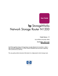
The front of the HP N1200-320 4Gb Network Storage Router is shown in Figure 1.
Figure 1 HP N1200-320 4Gb Network Storage Router front panel
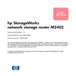
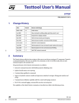
The back of the HP N1200-320 4Gb Network Storage Router is shown in Figure 2.
Figure 2 HP N1200-320 4Gb Network Storage Router back panel
Table 2 HP N1200-320 4Gb Network Storage Router
Number
Description
1
Power connector
2
On/Off switch
3
Cooling vents
4
Reset access hole
5
Serial port
6
10/100 Ethernet port
7
Fibre Channel port
8
Two SCSI busses
In addition to Fibre Channel and SCSI interfaces, there are Ethernet and serial ports that provide
connectivity for configuration and management access. The LEDs (operation indicators) provide basic
status information. A reset access hole is also provided for a manually forced reboot of the network storage
router.
N1200-320 4Gb Network Storage Router user and service guide
9
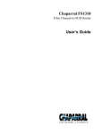
Operation indicators
The HP N1200-320 4Gb Network Storage Router has LED indicators for monitoring overall status as
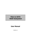
shown in Figure 3.
Figure 3 Operation indictors
Table 3 Operation indicators
Number
Description
1
Power and Fault (Pwr) LED
2
Fibre Channel port LEDs link (LNK) indicator (top) and activity (ACT) indicator (bottom)
3
SCSI bus 0, 1 LEDs
4
Ethernet LED link (LNK) indicator
5
Ethernet LED activity (ACT) indicator
The LED functionality of the network storage router is detailed below:
• Power and Fault (Pwr) – The bi-color LED is green when power is active, and is continuously amber
when the network storage router detects a fault condition.
• Fibre Channel LNK/ACT– When green, the LNK indicator signifies a good Fibre Channel link. When
green, the ACT indicator signifies Fibre channel port activity.
• SCSI bus (0, 1) – When lit, these green indicator LEDS signifiy SCSI activity for the associated bus.
• Ethernet (10/100) – The LNK indicator (left) will stay permanently lit to indicate an Ethernet link. The
ACT indicator (right) should flash to indicate Ethernet activity.
10
Introduction
How the HP N1200-320 4Gb Network Storage Router works
The network storage router is a device that translates the Fibre Channel Protocol (FCP) to and from the SCSI
Protocol—transparently transferring commands, data, and status information—so that both the Fibre
Channel (FC) and SCSI devices and hosts can communicate with each other. Interconnection is provided
between two SCSI buses and one Fibre Channel Arbitrated Loop or Switched Fabric, making use of Fibre
Channel’s ability to encapsulate SCSI protocol packets.
Processing SCSI information
The following section describes how the network storage router processes SCSI information when attached
to FC hosts.
1. A FC host issues a command, then encapsulates the command in the FC protocol and sends the packet
to the network storage router.
2. The network storage router receives the packet, interprets the FC information, and places the packet in
buffer memory.
3. The processor interprets the information and programs an internal SCSI controller to process the
transaction.
4. The SCSI controller sends the command to the SCSI device (target).
5. The SCSI target interprets the command and executes it.
6. Data flows between the FC host and SCSI target through payload buffers.
7. Response information flows from the SCSI target back to the FC host.
HP N1200-320 4Gb Network Storage Router features
Fibre Channel features
• One FC port (selectable between 4.25, 2.125 and 1.0625 Gbps)
• Fibre Channel Arbitrated Loop (FC-AL) including Point-to-Point configurations in arbitrated loop
topology only and Switched Fabric (FC-SW) topologies
• Private Loop Direct Attach (PLDA) profile compliant
• Class 3 operation with SCSI-FCP protocol
• Supports FCP-2 error recovery protocol as specified in FCP-2 rev. 04 and 05 for use with streaming
devices (such as tape)
• Optical SFP support (Shortwave)
SCSI bus features
• Auto-negotiation for Narrow, Wide, Fast, and up to Ultra320
• Concurrent commands, tagged command queuing and disconnect/reconnect
• SCSI-2 and SCSI-3 protocols
• Connection type is VHDCI 68-pin D shell, P type connectors
• LVD/single-ended termination
• Tape, optical, and changer devices
Management features
• Network storage router LUN commands
• Out-of-band Ethernet TCP/IP management access
• DHCP for easier network addressing
• Serial 3-pin connector for terminal access
• Ethernet RJ-45 connector for FTP, Telnet, and Web browser access
• Firmware that can be updated in the field
• SCC (FC only), Indexed, and Auto Assigned addressing modes
N1200-320 4Gb Network Storage Router user and service guide
11
External indicators
• Fibre Channel link status and activity LEDs
• SCSI bus activity LED
• Ethernet link status and activity LEDs
• Power/Fault LED
HP N1200-320 4Gb Network Storage Router benefits
The network storage router is designed to connect SCSI devices into a Fibre Channel (FC) fabric or loop.
The network storage router comes with one 4 Gb/s Fibre Channel port and two LVD/SE SCSI buses.
The Fibre Channel ports can be set for 1, 2, or 4 Gb/s speeds and can connect in arbitrated loop
(including point-to-point configurations) or switched fabric topologies. SCSI buses automatically negotiate
for Fast, Narrow, Wide, and up to Ultra320 SCSI.
Operating and Non-operating environments
Operating environment
• 0 to 50°C, 32 to 122°F
• 5 to 80% relative humidity (non-condensing)
Non-operating environment
• -40 to +55°C, -40 to 131°F
• 0 to 92% relative humidity (non-condensing)
12
Introduction
2
Installation, cabling, and setup
NOTE: Read this chapter carefully and completely before working with the network storage router.
Identifying product components
The network storage router kit:
• HP N1200-320 4Gb Network Storage Router
• Accessory kit
• Two rack mount assembly rails
• Two rack mount extender brackets
• One bag of mounting hardware with: eight #10-32 x 6 Phillips screws, and eight #6-32x 312
Phillips screws
• Documentation bundle
• Documentation CD
• Safety CD
• Warranty guide
• HP product documentation survey
• Stick-on feet
• Serial cable
• Power cable
• Getting Started poster
Typical installation configuration tasks
• Change the Administrative password if desired (see ”User security settings” on page 38)
• Change the network settings if needed (see ”Network configuration” on page 36)
• Set the date and time (see ”Real-Time Clock configuration” on page 39)
• Verify that the default map is Indexed (see ”Mapping menu” on page 47)
• Edit the Fibre Channel Port 0 map so that it is filled with the SCSI devices (library and drives) that are
communicating over Fibre Channel (see ”Fibre Channel port configuration” on page 42)
• Assign the Fibe Channel Port 0 map to any hosts that need to communicate with the SCSI devices
(library and drives) (see ”Fibre Channel port configuration” on page 42)
Installing the HP N1200-320 4Gb Network Storage Router
Remove the network storage router from the box and place it on a flat and stable work surface. Save the
packaging materials in the event the router will be shipped in the future.
The N1200-320 4Gb Network Storage router can be placed on a desktop or installed in a standard
19-inch rack. When considering a location, make sure the airflow area surrounding the front and back of
the router is unobstructed.
IMPORTANT:
The size of the router and it’s rail assembly is 1U.
N1200-320 4Gb Network Storage Router user and service guide
13
Desktop installation
Remove the router from the protective bag. Attach the stick-on feet to the bottom four corners of the router.
Place the router on a flat, level table or desktop making sure the airflow vents are clear of obstructions.
WARNING! Do not place objects on top of the network storage router.
Rack mount installation
IMPORTANT:
The size of the router and it’s rail assembly is 1U.
The following items in the N1200-320 4Gb Network Storage Router kit are used to install the router into a
rack:
• Two rack mount assembly rails
• Two rack mount extender brackets
• One bag of mounting hardware to include eight #10-32x 6 Phillips screws, and eight #6-32x 312
Phillips screws
IMPORTANT:
You need a #2 Phillips and a #2 flat-head screwdriver for this procedure.
To install the network storage router into a rack, determine where the router will be installed in the rack,
making sure the airflow vents remain clear of obstructions.
Separate the rack mount rails
1. Separate the inner rail from the outer rail by placing a thumb over the circular hole at the front-end of
the inner rail, and extend the inner rail out from the outer rail until it locks into place.
2. Press the spring latch on the back of the inner rails to release the lock.
3. While holding down the spring latch, extend the inner rail until the two rails separate.
4. Repeat this process to separate the other set of rails.
Figure 4 Separate rack mount rails
14
Installation, cabling, and setup
Attach the outer rail assembly to the rack
NOTE: The size of the router and the rail assembly is 1U.
1. Determine the correct rack location.
2. Align the three screw holes on the front of the outer rail assembly with the front of the rack. All three
holes must be exactly aligned.
3. With the outer rail assembly flush against the inside front of the rack, insert two 10-32 x 6 Phillips
screws, and tighten. Do not insert a screw in the center hole of the bracket.
Figure 5 Attaching the outer rail assembly to the rack
N1200-320 4Gb Network Storage Router user and service guide
15
Attach the rear extension bracket
1. Loosen the screw on the rear extension bracket of the outer rail assembly.
2. While holding the outer rail assembly level, extend the rear extension bracket to the inside of the rear
of the rack.
3. Attach the rear extension bracket to the rear of the rack using two of the 10-32 x 6 Phillips screws.
4. With the outer rail assembly in place, tighten the screw that connects the rear extension bracket to the
outer rail.
5. Repeat this process to attach the remaining outer rail assembly to the other side of the rack.
Figure 6 Attaching the rear extension bracket
Attach the rails to the network storage router
1. With the spring latch facing away from the router (4 in Figure 7) and the circular hole facing the front
of the router (2 in Figure 7), align the first screw hole on the rail (3 in Figure 7) with the center screw
hole on the router. Using this alignment, two screw holes will be aligned and the rail will extend out
from the front of the router approximately eight inches (1 in Figure 7).
2. Secure the rail to the router using two 6-32x 312 Phillips screws.
3. Repeat this process to attach the inner rail to the other side of the router.
Figure 7 Attaching the rails to the router
16
Installation, cabling, and setup
Install the router into the rack
1. Move the ball-bearing slide on each of the outer rails towards the front of the rack.
2. From the front of the rack, with the front side of the router facing out, align the inner and the outer rails
and slide the inner rail into the outer rail.
3. When the rails lock in place, press in the spring latches on each of the inner rails and push the router
into the rack.
Figure 8 Installing the router in the rack
Connect the power cord
IMPORTANT: Before supplying power to the network storage router, HP recommends setting up serial port
communications with your host computer, unless serial I/O was previously established and is currently
running (see ”Setting up serial port communications” on page 18).
IMPORTANT: The power cord shipped with the network storage router is a 120 VAC three-conductor
power cord for use in the United States and Canada. If the router is being installed outside the United
States or Canada, the appropriate power cord should be purchased.
Connect the power cord to the power connector on the back of the router. Connect the other end of the
power cord to a grounded voltage source.
Figure 9 Power cord connection
N1200-320 4Gb Network Storage Router user and service guide
17
Setting up serial port communications
The network storage router is designed to communicate with a terminal or any operating system utilizing
a terminal emulator. For example, most Windows® operating systems can use a terminal. Be sure the
baud rate, data bits, stop bits, parity, and flow control are set correctly.
To set up serial communications with the network storage router:
1. Plug the serial cable into one of the host computer’s serial ports (COM1 or COM2), and then plug the
other end of the serial cable into the network storage router’s serial port (see Figure 2 on page 9).
2. Start the terminal emulator.
3. Set the terminal emulator to use the appropriate COM port.
4. Specify the following settings for the port:
Baud Rate:
9600, 19200, 38400, 57600, or 115200
(Autobaud only recognizes these baud rates)
Data Bits:
8
Stop Bits:
1
Parity:
None
Flow Control:
None or XON/XOFF
NOTE: Before initially applying power to the network storage router, make sure all the SCSI devices are
powered on first, and that they have finished performing individual self tests. This helps to ensure that
device discovery works correctly.
5. Apply power to the network storage router. The power-up process can take up to 90 seconds. Once
complete, the main menu should be accessible.
18
Installation, cabling, and setup
Cabling the N1200-320 4Gb Network Storage Router
NOTE: Refer to the HP StorageWorks MSL2024 or the MSL4048 Tape Library User and Service Guide for
detailed tape library information.
Interfaces and connections
There are four types of interfaces to the network storage router:
• Fibre Channel
• SCSI
• 3-pin serial port
• Ethernet
The 3-pin serial and Ethernet ports are used for configuration and management of the network storage
router.
For convenience in configuring ports, key information is indicated on the back panel of the network
storage router such as WWN name, WWP name, and Ethernet MAC ID (Physical Address).
Fibre Channel connections
Before connecting the network storage router to other devices, it is important to understand the
configuration requirements of the environment to which it is connected.
IMPORTANT: Failure to correctly configure a Fibre Channel device may impair the operation of the
Storage Area Network (SAN) to which it is attached.
Typical installations have the network storage router connected to a Switched Fabric environment. For an
Arbitrated Loop, the unit can be directly attached to the Fibre Channel host bus adapter. In Fibre Channel
switched environments, the switch is also directly attached to the network storage router.
Both FC switches and hubs may allow for individual ports to be configured for different media types. The
network storage router must be connected to the hub or switch port with the appropriate FC cabling for the
media type in use on both the network storage router and the port to which it is connected.
The network storage router supports various Fibre Channel media types through the use of external Small
Form Factor Pluggable Transceivers (SFPs).
Supported media type: Multi-Mode Fiber - 4.25 Gbit Dual LC connectors.
To connect the network storage router to the Fibre Channel SAN:
1. Locate the Fibre Channel port on the network storage router (see Figure 2 on page 9).
2. Remove the rubber protector from the SFP.
3. With the network storage router powered off, connect the router into the Fibre Channel environment
using the appropriate cabling. The FC optical connector on the network storage router is keyed. Be sure
to insert the cable connectors in the proper orientation.
N1200-320 4Gb Network Storage Router user and service guide
19
SCSI connection
CAUTION: SCSI ports on the network storage router are not hot-pluggable. Power off the network
storage router whenever connecting/disconnecting the SCSI cables.
The network storage router can support Fast/Ultra320 Narrow/Wide SCSI, depending on the specific
configuration. The network storage router is factory configured to support LVD/Single-Ended buses. Two
VHDCI 68-pin D-shell, P-type connectors are available, allowing the unit to be attached at the end of up to
two SCSI buses. The network storage router must always be installed at the end of SCSI buses.
The network storage router supplies termination power (TERMPWR) to each SCSI bus. An internal
self-resetting fuse in the TERMPWR resets after a fault is cleared.
CAUTION: Do not plug HVD devices to an LVD/SE bus. Failure to follow this caution may result in severe
damage to equipment.
To connect the network storage router to a SCSI bus:
1. Power off the network storage router.
2. Power off the SCSI devices on this bus.
3. Connect a SCSI cable to one of the SCSI connectors on the router. The network storage router should
always be installed at the end of the SCSI bus.
4. Make sure that the bus is terminated correctly. By default, the network storage router is automatically
terminated. However, the device at the other end of the bus must also be terminated.
Ethernet connection
A 10/100BaseT Ethernet connection provides management and configuration access. The RJ-45
connector on the unit can be directly connected to a standard 10/100BaseT Ethernet network.
NOTE: You should change the pre-filled in settings if you disable DHCP, because while they are valid
settings, a conflict occurs if more then one network storage router is on the network with these initial
settings.
Setting the IP network address is recommended, but not required, in order to configure the network
storage router from this port. The IP network address can be manually assigned or dynamically assigned
(using DHCP). The default network configuration is DHCP, but if DHCP is turned off, the initial value for
the IP address is 1.1.1.1, the Subnet is 255.255.255.0, and the Gateway is 0.0.0.0.
Depending on the network environment, you may be able to temporarily use the IP address of 1.1.1.1 to
configure the network storage router. For more about the IP network address, refer to ”Network
configuration” on page 36.
Ethernet capabilities include Telnet support for configuration and management and FTP support for other
management capabilities.
20
Installation, cabling, and setup
Serial port connection
The 3-pin connector on the network storage router provides a serial port that is compatible with RS-232
signaling levels. The network storage router is designed to communicate with a terminal or any operating
system using a terminal emulator. The baud rate, data bits, stop bits, parity, and flow control of both the
network storage router and the host system must use the same settings. The Autobaud feature described
below provides an effective method to set the baud rate of the network storage router and host system.
Autobaud feature
The Autobaud feature automatically configures the baud rate on the network storage router. Once you set
the baud rate in the terminal emulator, wait until the network storage router completes the Power-On Self
Test (POST) and then the firmware initialization process. This can take up to 90 seconds, during which
time the POST and initialization information may or may not be visible on the terminal or terminal
emulator. After this process has completed, you can press the Enter key slowly seven or eight times (or just
type shift-z) and the network storage router automatically detects the baud rate being used by the
serial port. The baud rate is then saved in the network storage router’s configuration and is retained
through future power cycles.
NOTE: Pressing the Enter key before the POST has completed is of no benefit to the Autobaud feature.
Wait at least 90 seconds until both the POST and the firmware Initialization processes have completed
before pressing the Enter key.
NOTE: If there is no response using the Enter key, press the space bar slowly seven or eight times, and
then press the Enter key slowly seven or eight times.
The baud rate used by the terminal or terminal emulator must be 9600, 19200, 38400, 57600, or
115200 for the Autobaud feature to recognize it. The network storage router does not function properly
at any other baud rate.
N1200-320 4Gb Network Storage Router user and service guide
21
22
Installation, cabling, and setup
3
Device management
To provide connectivity between hosts and devices, it is necessary for the network storage router to be
recognized with an address on the connected Fibre Channel network.
SCSI bus configuration
The network storage router provides the capability to reset SCSI buses during the network storage router
boot cycle. This allows the devices on a SCSI bus to be set to a known state. Configuration provides for
the SCSI bus reset feature to be enabled or disabled.
The network storage router negotiates for the maximum values for transfer rates and bandwidth on a SCSI
bus. If an attached SCSI device does not allow the full rates, the network storage router uses the best rate
it can negotiate for that device. Negotiation is on a device specific basis, so the unit can support a mix of
SCSI device types on the same SCSI bus.
FC port configuration
By default, the configuration of the FC port on the network storage router is set to N_Port mode. For more
information, see the Fibre Channel Configuration sections in ”N1200-320 4Gb Network Storage Router
management” on page 27 and ”Fibre Channel port configuration” on page 42.
FC arbitrated loop addressing
On a Fibre Channel Arbitrated Loop, each device appears as an Arbitrated Loop Physical Address
(AL_PA). To obtain an AL_PA, two addressing methods, called soft and hard addressing, can be used by
the network storage router. Soft addressing is the default setting. For hard addressing, the user specifies
the AL_PA of the network storage router.
Soft addressing
When acquiring a soft address, the network storage router acquires the first available loop address,
starting from address 01 and moving up the list of available AL_PAs in the chart from 01 to EF. In this
mode, the network storage router obtains an available address automatically and then participates on the
FC loop, as long as there is at least one address available on the loop connected to the network storage
router. Fibre Channel supports up to 126 devices on an Arbitrated Loop.
Hard addressing
When acquiring a hard address, the network storage router attempts to acquire the AL_PA value specified
by the user in the configuration settings. If the desired address is not available at loop initialization time,
the network storage router comes up on the FC loop using an available soft address. This allows both the
loop and the unit to continue to operate. An example of this scenario would be when another device on
the Arbitrated Loop has acquired the same address as that configured on the network storage router.
Hard addressing is recommended for FC Arbitrated Loop environments where it is important that the FC
device addresses do not change. Device address changes can affect the mapping represented by the host
operating system to the application, and have adverse effects. An example of this would be a tape library
installation, where the application configuration requires fixed device identification for proper operation.
Hard addressing ensures that the device identification to the application remains constant.
FC switched fabric addressing
When connected to a Fibre Channel switch, the network storage router is identified to the switch as a
unique device by the factory programmed World Wide Name (WWN) and the World Wide Port Names
(WWPN), which are derived from the WWN.
N1200-320 4Gb Network Storage Router user and service guide
23
Discovery
Discovery is a feature that makes it easy to display attached FC and SCSI target devices and have them
mapped automatically on the host side for the connected bus/port.
There are two discovery methods available—Manual Discovery and Auto Discovery. Auto Discovery can
be set to occur after either reboot events (when the card reboots) or link-up events (for instance, when
cables are attached or a hub is rebooted). Discovery can also be turned off by setting the network storage
router to Manual Discovery Only. The default setting for FC Discovery is Manual Discovery.
For specific information on Discovery settings, see the Fibre Channel configuration and SCSI
configuration sections in ”N1200-320 4Gb Network Storage Router management” on page 27 and
”Discovery menu” on page 45.
Host bus adapter configuration
A host system using a Fibre Channel Host Bus Adapter (HBA) typically maps devices into the existing
device mapping scheme used by the host operating system. Refer to the HBA manual for the mapping
table.
Mapping usually involves pairing FC AL_PAs to SCSI target addresses. The HBA claims enough SCSI bus
entries to allow for 125 FC targets to map to SCSI bus:Target entries. This is usually done by a fixed
mapping of AL_PA to Bus:Target. In such a configuration, the network storage router corresponds to a
Bus:Target identifier, with the SCSI devices attached to the network storage router appearing as logical
units (LUNs). Operating systems can extend the available SCSI limit of 15 targets per bus. Although this is
not an issue for the operating system or most applications, there are cases where older applications can
have expectations about what are valid SCSI IDs, and not correctly handle certain mappings. In
particular, applications have been seen to exhibit difficulties addressing target IDs greater than 15 (e.g.
16 and up). This problem can be resolved by configuring the network storage router to use hard
addressing, and setting the AL_PA used by the unit to a value that the HBA will map to an ID with a value
less than 16.
For example, depending on the FC HBA, if the hard AL_PA selection is 1, the network storage router
address is 1. If the selection is 125, the network storage router address is 0xEF. Some FC HBAs configure
differently, so verify the AL_PA by reviewing the documentation for the HBA.
Logical unit management
Because SAN resources can be shared, multiple hosts can have access to the same devices on the SAN.
To prevent conflicts, the network storage router provides the means to restrict access and only allow hosts
to find and access selected devices. Simple LUN masking can restrict access, but many times this leaves
gaps in the list of LUNs presented to a host, since devices are always associated with fixed LUNs. The
network storage router, however, provides controlled access to devices by use of LUN management,
which goes beyond simple LUN masking.
LUN Management is the ability to present different hosts with different views of the devices accessed
through the network storage router. For example, one FC host may see three disk LUNs and a tape LUN at
LUNs 0 to 3 when it performs discovery on the network storage router. Another FC host may only discover
a tape LUN at LUN 0. Not only can the administrator control which devices a host may access, but also
which LUNs are used to access these devices.
LUN Management is accomplished by allowing the administrator to configure multiple maps, each of
which may present a different view of the devices behind the network storage router. Each host accessing
the network storage router can be associated with a specific map.
For a host connected to an FC port, a map is a table of LUNs where each entry in the table is either empty
or contains device address information needed to route commands to the appropriate device.
The FC port on the network storage router has a set of maps which include user defined maps and a few
special predefined maps.
There are currently four special predefined maps: Indexed, Auto Assigned, SCC, and Port 0 device maps.
Until a user configures the network storage router otherwise, the default map setting is Indexed.
24
Device management
• The Indexed map is initially empty and can be modified by the user, however, this is not
recommended.
• The Auto Assigned map is built dynamically, and contains all the devices found during discovery. This
map changes automatically any time the discovery process finds a change in the devices attached to
the network storage router. This map can be displayed, but cannot be modified directly by the user.
• The SCC map is only available on the FC port and contains a single entry. LUN 0 is an network
storage router LUN, and access to devices behind the controller is handled by using SCC logical unit
addressing.
When a host sends a command to the network storage router, the network storage router selects which
map to use, based on the ID of the host sending the command. For FC ports, the host ID is the World
Wide Name. For SCSI buses, the host ID is the initiator ID (0 - 15). When a host is unknown to the
network storage router, or is not attached to a specific map, the network storage router uses the default
setting for mapping. The default setting for each port can be set to Auto-assigned, Indexed, or SCC
(which applies to the FC port only) by the user.
N1200-320 4Gb Network Storage Router user and service guide
25
26
Device management
4
N1200-320 4Gb Network Storage Router
management
The HP N1200-320 4Gb Network Storage Router can be managed over the following user interfaces:
• Over the serial port via a terminal or a terminal emulation utility (see ”Setting up serial port
communications” on page 18).
• Over Ethernet via a Telnet utility or an HTTP-based interface called Visual Manager. Additionally, FTP
support provides additional management functionality (see ”Visual manager user interface” on
page 31).
Before attempting to configure the network storage router, a basic understanding of Fibre Channel and
SCSI devices is recommended.
NOTE: For information on SCSI standards, refer to publications from the X3T10 committee of ANSI
(American National Standards Institute). For information on Fibre Channel standards, refer to publications
from the X3T11 committee of ANSI. For those who are interested in purchasing approved American
National Standards and Technical Reports, you can contact ANSI at (212) 642-4900.
Configuration methods
The network storage router can be configured over the serial port via a terminal or terminal emulation
utility, over Ethernet via a Telnet utility or Web browser. FTP is also supported on Ethernet.
Serial port management access
The serial port allows for configuration of device characteristics from an attached terminal or terminal
emulator (see ”Setting up serial port communications” on page 18).
NOTE: A Serial connection cannot be made if a Telnet session (discussed later) is already open. If a user
attempts to open a serial connection while a Telnet session is already open, the following message
appears over the serial interface:
System in use via Telnet. Shell restarted.
The serial interface resumes working when the Telnet session closes.
Out-of-band Ethernet management access
DHCP is enabled by default. The first time you use the network storage router, use the serial interface to
identify the network settings that were assigned from the DHCP server, or to set a new static setting.
When DHCP is disabled, the pre-filled in values are IP address 1.1.1.1, a subnet mask of 255.255.255.0,
and a gateway address of 0.0.0.0. HP recommends that at a minimum, the IP address should be changed.
CAUTION: HP strongly recommends not having two network storage routers using the pre-filled in static IP
address on the same network, as this causes a conflict.
When setting the IP address for the network storage router, there are two options:
• The first option is to enter a fixed, or permanent IP address for the network storage router.
• The second option is to enable DHCP on the network storage router, so that a DHCP server (on the
Ethernet network used by the network storage router) can assign a dynamic IP address to the network
storage router.
N1200-320 4Gb Network Storage Router user and service guide
27
Your DHCP server may also allow you to set up an extended lease reservation for an IP address, by
providing the server with the Ethernet MAC address of the network storage router. This configures the
DHCP server to always provide the same IP address to the network storage router. This setup can be
useful for remote management of the network storage router via Telnet. Because the method of setting up
a lease reservation varies depending on the DHCP server being used, HP recommends that you contact
your Network Administrator for assistance.
For more information about enabling DHCP on the network storage router, see ”Enabling DHCP on the HP
N1200-320 4Gb Network Storage Router” on page 117.
Command Line Interface
The network storage router is capable of holding Telnet sessions for configuration purposes. Access to the
configuration menus via the serial port will be disabled when a Telnet session is connected. To open a
Telnet session, the IP address of the network storage router and a Telnet client utility are required.
NOTE: Rebooting the network storage router closes the Telnet session. After the network storage router
reboots and completes POST, the user must restart or re-open the Telnet session.
NOTE: Resetting to factory defaults from the Telnet interface does not affect Ethernet activity. User
configured values for the IP address, gateway, and subnet mask are retained after the network storage
router reboots. User name and password are not retained.
NOTE: The network storage router supports only one Telnet session at a time.
From most Windows systems, users can start a Telnet session from the DOS (or Command) prompt using
the following steps:
1. From the Windows Start menu, open the DOS (or Command) prompt window.
2. At the ‘>’ prompt, enter the following command
TELNET <IP address>
where <IP address> is the IP address of the network storage router. This starts a Telnet session
window for the network storage router.
3. Enter root for the default user name and password for the default password. HP recommends that
you change the user name and password as soon as possible.
4. Access configuration options in the same way used for the serial interface.
5. To exit the Telnet session, select the Disconnect option from your Telnet client utility. In most Telnet
utilities, this option is available as a menu item. If working from the Command Prompt in Windows,
simply close the window to end the session.
28
N1200-320 4Gb Network Storage Router management
Visual manager
The network storage router allows any standard Internet Web browser to view and change the network
storage router’s configuration with the Visual Manager interface. Information is dynamically generated in
an HTML format by the network storage router, so that Web browsers can access it.
To access Visual Manager, enter the IP address of the network storage router into the Address field of a
Web browser. Or, you can enter a URL using a host name defined by the user—for instance,
http://HPN1200-3204Gb (but the user must define the host name on the DNS server first for this to work).
To make changes to network storage router settings, use standard keyboard and mouse controls to input
information, and then select the Submit button to send the changes to the network storage router.
A user name and password are required before any changes can be submitted. The default user name is
root and the default password is password. HP recommends that you change the user name and
password as soon as possible (see ”User name and password” on page 38).
Other than dynamic mapping changes, any other changes will not take effect until the next time the
network storage router reboots. You can force the network storage router to reboot by selecting the
Reboot option.
For more information about the Visual Manager interface, refer to ”Visual manager access” on page 31.
NOTE: For the VM interface’s dynamic display of the network storage router configuration to be
presented properly, use version 6.2 or later of Netscape’s browser on non-Solaris platforms, or Netscape
version 6.2.3 for Solaris platforms. If using Internet Explorer, use revision 6.0 or later.
FTP
The network storage router includes support of File Transfer Protocol (FTP) for updating firmware, saving
trace buffers, and backing up/restoring of configuration settings. FTP functionality is described in more
detail in ”Using the Command Line Interface” on page 59. There is also an FTP Utility available within
Visual Manager (VM) that is described in ”FTP utility access” on page 51.
Inband SCSI-3 commands
The network storage router supports a set of SCSI-3 commands that can be received as FCP commands
over the Fibre Channel ports. When using these commands, they must be sent to a tape LUN or network
storage router LUN of the network storage router. For more information, see ”Inband SCSI-3 commands”
on page 109 and ”HP N1200-320 4Gb Network Storage Router features” on page 11.
N1200-320 4Gb Network Storage Router user and service guide
29
30
N1200-320 4Gb Network Storage Router management
5
Visual manager user interface
The HP N1200-320 4Gb Network Storage Router allows any standard Internet Web browser to view
and change the network storage router’s configuration with the Visual Manager interface. Information is
dynamically generated in an HTML format by the network storage router so that Web browsers can
access it.
To access Visual Manager, enter the IP address of the network storage router into the address field of a
Web browser. Or, enter a URL using a host name defined by the user—for instance,
http://HPN1200-3204Gb. (But the user must define the host name on the DNS server first, for this to
work).
To make changes to network storage router settings, use standard keyboard and mouse controls to input
information, and then select the Submit button to send the changes to the network storage router.
A user name and password are required before any changes can be submitted. The default user name is
root and the default password is password. HP recommends that you change the user name and
password as soon as possible (see ”User name and password” on page 38).
Other than dynamic mapping changes, any other changes will not take effect until the next time the
network storage router reboots. You can force the network storage router to reboot by selecting the
Reboot option.
NOTE: For the VM interface’s dynamic display of the network storage router configuration to be
presented properly, use version 6.2 or later of Netscape’s browser on non-Solaris platforms, or Netscape
version 6.2.3 for Solaris platforms. If using Internet Explorer, use revision 6.0 or later.
Visual manager access
Visual Manager (VM) can be accessed from any standard Web browser:
1. Connect an RJ45 Ethernet cable to the back of the network storage router.
2. Obtain the IP address of the network storage router.
3. Enter the network storage router IP address in the address field of the Web browser of the host
computer.
NOTE: To access VM, the network storage router must be assigned a valid IP address. The factory default
setting for the IP address is DHCP.
NOTE: If you don’t know the IP address of the network storage router, connect to the network storage
router using the serial connection (see ”Setting up serial port communications” on page 18). You can view
and change the current settings from the serial interface’s Ethernet menu.
The Visual Manager home page is displayed, showing network storage router status information. The
home page is accessible to anyone who knows the network storage router IP address.
4. Select the desired menu option to access menus and screens.The Password dialog box is displayed.
See Figure 10 on page 32 for an example of the Password Dialog box.
N1200-320 4Gb Network Storage Router user and service guide
31
5. Enter the authorized user name and password. The user name and password are case-sensitive.
The default user name is root and the default password is password.
Figure 10 Password dialog box
NOTE: HP recommends changing the user name and password from the defaults (see”User name and
password” on page 38).
NOTE: To end the current session of VM, the browser window must be closed. Navigating the browser to
another URL does not end the current session.
Main menu
Visual Manager menu structure
Figure 11 Visual Manager menu
32
Visual manager user interface
Home page
The Main menu home page is displayed when Visual Manager (VM) is accessed.
The home page contains status information, including a physical image of the network storage router (see
Figure 12).
Figure 12 Visual Manager Home page
Home page information includes:
• The HP logo is located in the upper left corner of the Home page. If the Internet is accessible to the
host, click the HP logo to open the web site.
• An illustration of the network storage router is located near the top of the home page. Figure 13 is an
example of this portion of the home page screen.
Figure 13 Network storage router image
• The network storage router image is interactive, allowing quick access to configuration menus:
• To display current settings and status for a port, click the corresponding port shown in the network
storage router image.
• To open a menu for making changes to the configuration for that particular port or bus, click the
desired Fibre Channel port or SCSI bus.
• To open the Network Configuration menu, click the Ethernet port.
• network storage router status information is located in the body of the home page and includes
platform information.
N1200-320 4Gb Network Storage Router user and service guide
33
• Main menu options:
• Home displays network storage router status information.
• System configures standard system components.
• Ports configures the Fibre Channel port and SCSI buses.
• Discovery displays devices and discovers new devices.
• Mapping displays and configures maps.
• Statistics displays network storage router statistics.
• Utilities configures utility settings.
• Report displays system information.
• Reboot restarts the network storage router.
System menu
The System menu is accessed from the Main menu and is used to view and configure serial, network, active
fabric, user, real-time clock, and factory settings reset (see Figure 14).
Figure 14 System screen
System menu:
• Serial configures the baud rate.
• Network configures Ethernet settings.
• Active Fabric configures Active Fabric settings.
• User configures user security settings such as the password.
• Real-Time Clock configures system date and time.
Reset menu:
• Factory Settings Reset restores factory default settings
34
Visual manager user interface
Serial configuration
The Serial screen is used to change the baud rate for the serial port (see Figure 15).
NOTE: If the Autobaud feature is being used, it may not be necessary to set the baud rate.
Figure 15 Serial screen
The current baud-rate setting is displayed.
Baud rate choices are:
• 9600
• 19200
• 38400
• 57600
• 115200
NOTE: HP recommends setting the baud rate to 115200.
N1200-320 4Gb Network Storage Router user and service guide
35
Network configuration
The Network screen is used to enter Ethernet configuration settings (see Figure 16).
Figure 16 Network screen
CAUTION: If this configuration is incorrectly set, processing difficulties may occur. Before changing this
setting, evaluate the need for the change and verify the desired setting. HP recommends backing up the
network storage router configuration to an external file before making changes to this setting.
Network menu options:
• Host name - to change the host name, enter an alphanumeric entry of one word, up to eight characters
in length. Select Submit.
• Ethernet Mode - the Ethernet Mode can be set to one of the following options, though 10/100Mps
(Auto-Neg.) is the default:
• 10 Mps Only
• 10/100Mps (Auto-Neg.) Default
• 100Mps (half duplex) Only
• 100Mps (full duplex) Only
NOTE: The Ethernet physical address is assigned by DHCP by default.
• IP Address - is the IP address of the network storage router.
• Subnet mask - is the IP subnet mask for the network storage router.
• IP Gateway - is the IP address of the gateway for the Ethernet network connected to the network
storage router.
• DHCP - enables or disables support for Dynamic Host Configuration Protocol (DHCP).
• When DHCP is enabled, the network storage router requests a dynamic IP address from a DHCP
server on the Ethernet network. The network storage router must be rebooted before an IP address
is requested from the DHCP server. After the network storage router is rebooted, the HTTP session
must be restarted. The IP address is different from the former non-DHCP IP address. You can now
use the serial interface to obtain the new IP address (see ”Perform configuration” on page 60).
36
Visual manager user interface
NOTE: To use the DHCP feature, a DHCP server must be operational on the Ethernet network. If the DHCP
feature is used when there is not a DHCP server, the standard for DHCP requires the network storage router
to wait three minutes for a response from a DHCP server before timing out.
Some DHCP servers allow an extended lease reservation to be set up for an IP address by providing
the server with the Ethernet MAC address. The DHCP server always provides the same IP address to
the network storage router. This setup can be useful for remote management of the network storage
router via Telnet or VM. Because the method of setting up an extended lease reservation varies,
depending on the DHCP server being used. Contact the Network Administrator for assistance.
Active fabric configuration
The Active Fabric (AF) screen allows setup of a fibre target LUN for the network storage router (see
Figure 17).
Figure 17 Active Fabric screen
NOTE: Increasing the number of Controller LUNS takes effect immediately. For all other changes, the
network storage router must be rebooted.
Active Fabric settings:
• ServerFree Backup Mode: NOT Supported
• Number of Controller LUNs: (default: 1) sets the number of controller LUNs reported by the network
storage router. The number must be in the range of 0 through 4.
• Controller LUNS in auto-assigned map go: settings are First or Last. Setting the choice to Last is
recommended. Setting the choice to First can cause issues with HP-UX. However, if working with an
OVMS host, it should be set to First.
N1200-320 4Gb Network Storage Router user and service guide
37
User security settings
User name and password
The User screen is used to set up network storage router security such as the user name and password (see
Figure 18).
Figure 18 User screen
User settings:
• User Name (default: root) is any alphanumeric combination.
• Password (default: password) is any alphanumeric combination. Passwords must be 8 to 11
characters in length.
• Confirm Password
The user name and password should be unique and kept confidential. HP recommends using a
combination of letters and numbers when creating the user name and password.
NOTE: These security settings affect all user interfaces of the network storage router.
38
Visual manager user interface
Real-Time Clock configuration
The Real-Time Clock screen is used to set the system time and date (see Figure 19).
Figure 19 Real-Time Clock screen
Date/time settings:
• Date Settings sets the month, day, and year (use a four-digit number to represent the year)
• Day of Week sets the day of the week.
• Time Settings sets the hours, minutes, and seconds.
The system clock is a 24-hour clock. There is no a.m. or p.m. designation. Example 1:00 p.m. is 13
hours, 00 minutes.
N1200-320 4Gb Network Storage Router user and service guide
39
Reset menu
The Reset menu is used to reset the network storage router to factory default settings (see Figure 20).
Figure 20 Reset to Factory Default screen
Current network storage router activities are disrupted while the unit resets the configuration to the factory
defaults and saves those options to FLASH memory.
CAUTION: Resetting the network storage router configuration to the factory defaults deletes custom maps
or map changes.
NOTE: Resetting to factory defaults through VM does not affect Ethernet connectivity. User-configured
values for the IP address and gateway are retained.
40
Visual manager user interface
Ports menu
Accessed from the Main menu, the Ports menu is used to view and to modify configuration settings of the
Fibre Channel port and SCSI buses (see Figure 21).
Figure 21 Ports menu
The initial screen display of the Ports menu includes summary information about each Fibre Channel port
and SCSI bus in the network storage router.
Ports menu tasks:
• Fibre Channel Port 0 configuration changes the Fibre Channel port settings.
• SCSI Bus 0, 1 configuration changes SCSI bus settings.
Each Ports menu option is discussed in the following subsections.
To view or make changes to a specific port or bus:
1. Select the port or bus from the menu bar on the left side of the screen or select the port or bus from the
network storage router image at the top of the screen.
2. Modify the setting.
3. Click Submit.
N1200-320 4Gb Network Storage Router user and service guide
41
Fibre Channel port configuration
When the Fibre Channel port is selected in Ports menu, the Fibre Channel Configuration screen is
displayed (see Figure 22).
Figure 22 Fibre Channel port 0 configuration settings screen
Fibre Channel port settings:
• Link Status indicates the port link status.
• Port Mode (default: N_Port) sets the port mode.
Port Mode settings:
• Auto Sense: In this mode, the Fibre Channel port tries to negotiate as a loop. If it is not successful,
then the Fibre Channel port negotiates as a fabric. If the port comes up as a loop, it then determines
whether it is on a private or public loop.
• N_Port: (default) This mode allows the network storage router to bypass the loop negotiation and
come up as a fabric only. If the network storage router is on a loop, and N_Port mode is selected,
an error in communication may occur.
• Use Hard AL_PA enables or disables Hard AL_PA usage.
• Hard AL_PA Settings displays the AL_PA Lookup Table.
Use the table to find the node number. This unique one-byte valid value (derived from an Arbitrated
Loop Topology defined in ANSI specification FC_AL version 4.5) is used for the Fibre Channel
configuration.
• Discovery Mode (default: Manual Discovery Only) determines how the network storage router discovers
new Fibre Channel devices.
Discovery mode settings:
• Auto Discovery on Reboot allows the network storage router to automatically discover all Fibre
Channel devices when rebooted or when link-up events occur, such as connecting cables or
rebooting network hubs.
• Both the ports and the devices behind the ports are discovered on all subsequent link-up events.
42
Visual manager user interface
• Discovery on Link Up allows the network storage router to automatically discover all Fibre Channel
devices when rebooted or when link-up events occur, such as connecting cables or rebooting
network hubs.
• Both the ports and the devices behind the ports are discovered for the first link-up event.
Subsequent link-up events only discover the ports and not the devices behind the ports.
• Manual Discovery Only (default) sets discovery of new devices to occur only after the user selects
the Discovery option from the Main menu or when a Registered State Change Notification (RSCN)
is received from a fabric.
• Buffered Tape Writes (default: enabled) enables or disables the Buffered Tape Write option.
CAUTION: If this configuration setting is incorrectly set, processing difficulties may occur. Before changing
this setting, evaluate the need for the change and verify the desired setting. HP recommends backing up
the network storage router configuration to an external file before making changes to this setting.
When enabled, to enhance performance, Buffered Tape Writes return status on consecutive write
commands prior to the tape device receiving data.
• Buffered Tape Queue Depth sets the Buffered Tape Queue Depth.
Select a setting of 0 through 10 from the drop-down list.
• Default Map (default: indexed) sets the current mapping mode for the selected port.
The current map can be set to:
• Indexed (default) (HP recommends that this map NOT be edited, even though the user is able to
edit the Indexed map.)
• Auto-assigned contains all the SCSI devices that are attached to the network storage router.
• SCC
• Performance Mode (default: 4 Gb/s) toggles between 1 Gb/s, 2 Gb/s, and 4 Gb/s.
NOTE: If Performance Mode is set incorrectly and the network storage router is plugged into a Loop or
Fabric, the unit will not light the LNK LED and may receive Framing errors due to the incorrect Fibre
Channel link speed.
• Force FCP Response Code toggles between Disabled and Enabled for support of HP-specific HBAs.
N1200-320 4Gb Network Storage Router user and service guide
43
SCSI bus configuration
When a SCSI bus is selected in the Ports menu, the SCSI Bus Configuration screen is displayed (see
Figure 23).
Figure 23 SCSI Bus 0, 1 configuration screens
SCSI bus configuration settings:
• Primary Initiator ID (default: 7) must be a unique ID.
• Discovery toggles between Enabled and Disabled, Enabled by default.
• Bus Reset on Boot toggles between Enabled and Disabled.
When enabled, the network storage router automatically resets SCSI buses during a power-up or
reboot of the library.
• Discovery Delay is the wait time after a power-up or reboot before discovering SCSI devices. HP
recommends setting the value to at least 30 seconds to ensure that all SCSI devices complete their
individual power-ups.
• SCSI Override Settings
• Overrides
44
Visual manager user interface
Discovery menu
Accessed from the Main menu, the Discovery menu is used to view existing, and discover new Target
devices (see Figure 24).
Figure 24 Discovery screen
To perform a manual discovery:
1. Select the Fibre Channel port or SCSI bus from the menu bar or the network storage router image.
2. Select Go.
Figure 25 Perform discovery on FC Port 0 screen
N1200-320 4Gb Network Storage Router user and service guide
45
Figure 26 Perform discovery on SCSI Bus 0 screen
46
Visual manager user interface
Mapping menu
Accessed from the Main menu, the Mapping menu is used to create or edit LUN maps and assign them to
hosts. (see Figure 27).
Figure 27 Mapping screen
NOTE: Indexed, Auto Assigned, and SCC maps cannot be deleted or renamed.
NOTE: SCC and Auto-Assigned maps cannot be cloned.
Each physical port/bus on the network storage router can have the following maps:
Table 4 Device map types
Map type
Generated by
Editable
Auto Assigned
System
No
Indexed (default)
System
Yes
Port 0 Device Map
System Generated/User Edited
Yes
SCC
System
No
Each map has a unique name and map ID; one of the maps must be identified as the current map.
Fibre Channel mapping tasks
Configuration tasks for Fibre Channel mapping includes:
• Viewing and changing Fibre Channel map information
• Viewing and changing Fibre Channel host information
Each task is discussed in the following paragraphs.
N1200-320 4Gb Network Storage Router user and service guide
47
Viewing and changing Fibre Channel map information
NOTE: Port 0 Device Map is the HP recommended map to be used for editing and assigning to hosts that
communicate with the library. The Indexed (default) map should not be used for editing, even though the
user is able to edit this map.
To view or change current Fibre Channel map information:
1. In the Mapping menu screen, select the desired map.
2. Select Edit/View in the Map section of the screen.
The Fibre Channel Map dialog box is displayed. Current map information is shown at the top of the
dialog box.
3. Enter the new settings and then select the appropriate action button.
NOTE: Bus/Target mapping mode is recommended.
NOTE: SCSI devices attached to a Fibre Channel must be mapped as sequential Fibre Channel LUNs
starting at LUN number 00. Skipping LUN numbers is not recommended when mapping Fibre Channel
LUNs because Fibre Channel Discovery stops the discovery process whenever an empty LUN position is
found.
NOTE: Auto-Assigned and SCC maps cannot be modified, cleared, filled, or have entries removed.
NOTE: Map settings are saved to memory when any button within the page is selected.
Viewing and changing Fibre Channel host information
NOTE: HP recommends setting the Index map as the default and allowing it to remain empty, while filling
a custom map (such as Port 0 Device Map) with only the hosts that need to communicate with the library or
drives.
To view or change current host information:
1. In the Mapping menu screen, select the desired map.
2. Click Edit/View in the Host section of the screen.
The Fibre Channel Host Name dialog box is displayed. Current host information is shown at the top of
the dialog box.
3. Enter the new map settings and then select Modify.
Fibre Channel Host Name settings:
• Host Name
• Host ID (hexadecimal)
• Port WWN Hi (hexadecimal) (service mode-restricted access)
• Port WWN Lo (hexadecimal) (service mode-restricted access)
• Node WWN Hi (hexadecimal) (service mode-restricted access)
• Node WWN Lo (hexadecimal) (service mode-restricted access)
• Map Name
48
Visual manager user interface
Statistics menu
Accessed from the Main menu, the Statistics menu is used to display Fibre Channel port and SCSI bus
information (see Figure 28).
Figure 28 Statistics menu
To view information for a specific port or bus, click the component on the menu bar or the network storage
router image. To refresh the display, select Reset FC & SCSI System Statistics.
N1200-320 4Gb Network Storage Router user and service guide
49
Utilities menu
Accessed from the Main menu, the Utilities menu is used to view and configure utility options (see
Figure 29).
Figure 29 Utilities menu
Utilities menu tasks:
• FTP Utility opens an FTP session.
• Trace Settings configures trace settings.
• Current Traces displays current trace information.
• Previous Traces displays previous trace information.
• Last Assert Traces displays last assert trace information.
• Clear Current Traces clears current trace information.
• Clear Assert Traces clear current trace information.
• Event Log Settings configures Event Log settings.
• Event Log displays the Event Log.
• Clear Event Log clears the Event Log.
• SCSI Command Tracking
Each Utilities menu option is discussed in the following sections.
50
Visual manager user interface
FTP utility access
The FTP utility screen is used to open an FTP session (see Figure 30).
Figure 30 FTP Utility screen
The FTP utility requires the use of a JAVA applet and prompts for permission to install the applet, if needed.
If the prompt is displayed, follow the on screen instructions to complete the installation. The FTP utility then
prompts for permission to run the applet.
NOTE: Internet access is required to verify the signature for the HP FTP applet and to download the JAVA
applet plug-in for your browser.
To open an FTP session:
1. Enter the User Name, Password, and the IP address of the network storage router.
2. Click Connect.
3. Select the local file to upload or download. If necessary, click Browse to scroll through a file list.
The following file types can be uploaded to the network storage router:
• Configuration (.cfg)
• Firmware (.dlx)
The following file types can be downloaded from the network storage router:
• Configuration (.cfg)
• Traces for the current boot cycle (curtrace.txt)
• Traces from the previous boot cycle (prvtrace.txt)
4. Click Binary Transfer mode.
5. Choose the desired task:
• To download a file, click Get.
• To upload a file, click Put.
N1200-320 4Gb Network Storage Router user and service guide
51
NOTE: If a valid firmware or configuration file is uploaded to the network storage router, an automatic
reboot occurs once the file has been received. The network storage router cannot be accessed from the
Visual Manager UI during the time that the reboot is in process, which is approximately 30 seconds.
Trace settings configuration
This menu allows the configuration of Trace Settings (see Figure 31).
Figure 31 Trace settings configurations screen
To change the settings, use the drop-down boxes and choose the desired setting. After all changes are
completed, select Submit. Table 5 is a brief description list of the trace settings.
Table 5 Trace Settings
52
Setting
Description
General Errors
Displays the most serious error and exception conditions
FCP Transport
Fibre Channel Protocol transport functionality is monitored and recorded
PS Transport
Parallel SCSI transport functionality is monitored and recorded
PS Driver
Parallel SCSI driver functionality is monitored and recorded
Timing
Timer functions are monitored and recorded
AF
Active Fabric firmware is monitored and recorded
Multi-Host Lib
Debugging capability for Multi-host library features
SFP Diagnostics
Optical transceiver status is monitored and recorded
FCP Driver
Fibre Channel Protocol driver functionality is monitored and recorded
FCP Management
Fibre Channel Protocol management functionality is monitored and recorded
PS Management
Parallel SCSI functionality is monitored and recorded
SG List
Scatter/gather list is monitored and recorded
FCP/RMI
Fibre Channel Protocol routing layer is monitored and recorded
Visual manager user interface
Table 5 Trace Settings
Setting
Description
INBAND
Controller management functionality is monitored and recorded
Queue Element
Debugging capability for specific network storage router resources
Current, previous, and last assert trace displays
These three Utilities menu screens show trace information.
• The Current Traces screen shows data since the network storage router was last booted.
• The Previous Traces screen shows data from the last boot cycle.
• The Last Assert Traces screen shows data since the last assertion.
Trace buffers can be cleared by selecting either the Clear Current Traces option or the Clear Assert Traces
option.
Clear current trace buffer or assert trace buffer
Trace buffers can be cleared by selecting either the Clear Current Traces option or the Clear Assert Traces
option. When the Clear Current Traces option is selected, a confirmation message appears to verify the
selection. If a response of Yes is given, the unit clears the current trace buffer. Current network storage
router activities are not disrupted while the buffer is cleared. Select the Submit button to finalize your
choice.
Event log settings
The Event Log Settings screen is used to configure Event Log filters (see Figure 32).
Figure 32 Event Log settings screen
Event Log settings:
• Disable/Enable Logging
• Emergency Events
• Alert Events
• Critical Events
• Error Events
N1200-320 4Gb Network Storage Router user and service guide
53
• Warning Events
• Notify Events
• Info Events
• Debug Events
• Log All Events
Event logging captures the last 215 events and then starts overwriting the log.
NOTE: To correlate event logging, correctly set the clock and date in the Real-Time Clock configuration
menu (see ”Real-Time Clock configuration” on page 39).
Event log display
The Event Log screen is used to view the Event Log (see Figure 33).
Figure 33 Event log display
54
Visual manager user interface
Clear event log
The Clear Event Log screen is used to clear the Event Log (see Figure 34). Current network storage router
activities are not disrupted.
Figure 34 Clear event log screen
SCSI command tracking
This menu provides options for setting up and logging SCSI commands that are received or transmitted by
the network storage router. Results are displayed in the Host/Device ID Table (see Figure 35).
Figure 35 SCSI command tracking
N1200-320 4Gb Network Storage Router user and service guide
55
While the network storage router’s current, previous, and last assert trace data does provide a complete
summary of events in a chronological fashion, SCSI Command Tracking adds the ability to filter the trace
data to show only the information related to the processing of specific SCSI commands.
• SCSI Command Tracking can be toggled to ON or OFF. When toggled ON and submitted, all SCSI
commands received or transmitted to or from the network storage router are then logged in the
SCSI Commands section shown on this screen. When set to OFF (and submitted), no SCSI commands
are logged.
• Previous entries for SCSI Command Tracking can also be cleared. Toggling the clear option to the ON
position and selecting the Submit button clears all previous entries.
• The settings for the Host/Device ID Table are used to filter the trace data such that a sub-set of the total
logged information is displayed under the SCSI Commands section. Logged data can be defined
according to the Protocol (FC, Other, or ALL), Type (Device, Host, or ALL), and Value (ID or ALL). For the
ID, this can be a specific FC LUN or Switch ID (S_ID) or some other specific value. Selecting the Submit
button activates the settings for Protocol, Type, and Value.
Report menu
Accessed from the Main menu, when Report is selected, a second window pops up and displays a
consolidated view of the following:
• Platform
• BIOS Initialization
• Bootup Initialization
• Serial
• Ethernet
• FC Port 0
• SFP Transceiver in FC Port 0
• SCSI Bus 0
• SCSI Bus 1
• Discovery Information
• Device Entries
• Mapping Information
• Active Initiators
• Trace Settings
• Current Traces
• Previous Traces
• Assert Traces
• Event Log Settings
• Event Log
56
Visual manager user interface
Reboot option
CAUTION: Confirm there is no activity, such as a backup in progress, before initiating a reboot because
network storage router activities will be disrupted.
Network storage router reboots are executed using this Main menu option (see Figure 36).
When the library is rebooted, current network storage router activities are disrupted. All submitted
configuration changes are activated during the boot-up process.
Figure 36 Reboot screen
The system automatically returns to the home page after the reboot has completed.
N1200-320 4Gb Network Storage Router user and service guide
57
58
Visual manager user interface
6
Using the Command Line Interface
This chapter describes specific configuration options available from the perspective of the Command Line
Interface (CLI). For an overview of using the other configuration methods available, see ”N1200-320
4Gb Network Storage Router management” on page 27.
The network storage router allows the user to access many configuration settings through the Command
Line Interface. Among these settings are:
• Serial, Ethernet, and fibre port configuration
• Fibre LUN mapping
• Assigning LUN maps to hosts
• Trace level settings
All of the above settings may be changed and saved.
NOTE: Unless otherwise indicated, configuration changes take effect when the system next powers on or
reboots.
Power-up messages
When the HP N1200-320 4Gb Network Storage Router powers on, a series of power-up messages
appear on the terminal or terminal emulation program for the serial port or the Telnet utility for Telnet
sessions.
A series of power-up self tests are performed as the network storage router starts (which can take up to 90
seconds), and messages related to these tests are visible from the serial port. If completed successfully, the
main menu appears, as shown in Figure 37.
NOTE: The illustrations in this chapter use Xs to represent numeric values for certain data fields, such as
the product release version and the revision of firmware.
NOTE: For the serial port, if you do not see messages over the Command Line Interface, you may need to
re-check your computer’s serial port settings.
\
The main menu appears as follows:
Figure 37 Main menu
HP StorageWorks N1200-320 4Gb Network Storage Router
X.XX.XX
XXXXXX
07/7/2005
XXXXXXXXXXXXXXXX
18:37:08
1) Perform Configuration
2) System Utilities
3) Display Trace and Assertion History
4) Reboot
5) Download a New Revision of The Firmware
Command >
N1200-320 4Gb Network Storage Router user and service guide
59
The main menu allows for various operations to be performed on the network storage router.
• Select 1 to access network storage router configuration settings.
• Select 2 to access System Utilities.
• Select 3 to display trace and assertion history.
• Select 4 to reboot the network storage router. A confirmation message appears to verify this action.
• Enter N to return to the System Utilities menu.
• Enter Y to restart the network storage router.
• Select 5 to download a new revision of the firmware. A confirmation message appears to verify this
action. (For additional information see ”Download a new revision of the firmware” on page 90.)
• Enter N to return to the Main menu.
• Enter Y for the network storage router to accept firmware data from the serial port.
Perform configuration
The Perform Configuration menu allows the administrator to configure the various options on the network
storage router. For most configuration changes to take effect, you must reboot the network storage router.
NOTE: Menus are not case sensitive. You can enter uppercase and lowercase characters
interchangeably, whenever menus indicate letters as choices.
Figure 38 Configuration menu
Configuration Menu
X.XX.XX
XXXXXX
07/7/2005
XXXXXXXXXXXXXXXX
08:56:22
1) Baud Rate Configuration
2) Ethernet Configuration
3) Fibre Channel Configuration
4) Parallel SCSI Configuration
5) Device Mapping
6) Trace and Event Settings Configuration
7) Real-Time Clock Configuration
8) Active Fabric Configuration
A) Save Configuration
B) Restore Last Saved Configuration
C) Reset to Factory Defaults
X) Return to main menu
60
Using the Command Line Interface
Baud rate configuration
This menu changes the baud rate used on the serial port. Select 1 through 5 for the appropriate baud rate
setting. If you are using the Autobaud feature, it may not be necessary to set a baud rate. See ”Autobaud
feature” on page 21 for more information on using the Autobaud feature. The default setting for the baud
rate is 115200.
Figure 39 Baud rate configuration menu
Baud Rate Configuration Menu
X.XX.XX
XXXXXX
XXXXXXXXXXXXXXXX
07/7/2005
08:56:22
1)
9600
2)
19200
3)
38400
4)
57600
5) * 115200
X) Return to previous menu
NOTE: The asterisk (*) symbol indicates the current setting for the baud rate.
N1200-320 4Gb Network Storage Router user and service guide
61
Ethernet configuration
This option allows for setting up all Ethernet network settings including IP address, subnet mask, IP
gateway, security settings, Ethernet mode, physical address, and host name.
Figure 40 Ethernet configuration menu
Ethernet Configuration Menu
X.XX.XX
XXXXXX
07/7/2005
XXXXXXXXXXXXXXXX
08:56:22
IP Address
: 192.168.60.203 [DHCP]
Subnet Mask
: 255.255.255.0
IP Gateway
: 192.168.60.1
Ethernet Physical Address
: 00:E0:02:E3:17:51
Ethernet Mode
: 10/100Mbps (Auto-Neg)
Host name
: network storage router
DHCP Configuration
: Enabled
1) Change IP Address
2) Change IP Subnet Mask
3) Change IP Gateway
4) Change Ethernet Physical Address
5) Toggle Ethernet Mode
6) Change Hostname
7) Toggle DHCP Configuration
8) Change Security Settings
X) Return to previous menu
• Select 1 to change the IP address of the network storage router.
• Select 2 to change the IP subnet mask for the network storage router.
• Select 3 to change the IP gateway for the Ethernet network of the network storage router.
• Select 4 to change the Ethernet physical address, or MAC address, of the network storage router.
Since Ethernet physical addresses are always assigned to Ethernet adapters by the manufacturers, HP
recommends that this setting not be changed.
• Select 5 to toggle the Ethernet mode among the following options:
• 10Mps Only
• 100Mps (half duplex) Only
• 100Mps (full duplex) Only
• 10/100Mps (Auto-Neg.)Default
• Select 6 to change the host name. This is an alphanumeric entry of one word up to eight characters
long.
NOTE: Do not use a capital Z as a part of the host name because this is the autobaud hot key used by
the MS Windows terminal utility for serial connections.
62
Using the Command Line Interface
• Select 7 to toggle the DHCP setting. This setting enables/disables support for Dynamic Configuration
Protocol. The default setting is enabled. When enabled, the network storage router retrieves a
dynamic IP address from a DHCP server located on the Ethernet network that the network storage
router is connected to.
If DHCP is disabled and then enabled, it is necessary to save the current configuration and reboot the
network storage router before an IP address can be requested from the DHCP server. Use the following
four steps:
a. Select X Return to previous menu.
b. Select A Save Configuration.
c. Select X Return to previous menu.
d. Select 4 Reboot.
After the network storage router finishes rebooting, the Main menu appears on the serial interface. For
Telnet, a new session needs to be opened to continue configuring the network storage router. DHCP
status can be verified from the Ethernet Configuration menu where DHCP Configuration is indicated as
Enabled, if DHCP has been successfully activated. Note that the IP address may also appear different
than the former non-DHCP IP address.
NOTE: To use the DHCP feature, a DHCP server must be operational on the Ethernet network used by the
network storage router. If the DHCP feature is used when there is no DHCP server, the standard for DHCP
requires that the network storage router wait three minutes for a response from a DHCP server before
timing out.
Your DHCP server may allow you to set up a extended lease reservation for an IP address by providing
the server with the Ethernet MAC address of the network storage router. This sets the DHCP server to
always provide the same IP address to the network storage router. This setup can be useful for remote
management of the network storage router via Telnet or Visual Manager. Because the method of setting
up a lease reservation varies depending on the DHCP server being used, HP recommends that you
contact your Network Administrator for assistance.
• Select 8 to change security settings, including the user name and password. User names and
passwords should be unique and kept confidential and HP recommends using a combination of letters
and numbers when creating user names and passwords.
N1200-320 4Gb Network Storage Router user and service guide
63
Fibre Channel configuration
This menu allows for setting the Fibre Channel Address method, Hard Address value, discovery mode,
WWN overrides, tape backup settings, default map value, and FC port mode.
Figure 41 Fibre Channel configuration menu
Fibre Channel Configuration Menu
X.XX.XX
XXXXXX
XXXXXXXXXXXXXXXX
07/7/2005
Current Fibre Channel Configuration -
08:56:22
Port 0:
FC Link Status
: DOWN
Node Name
: 0x100000E0 02031751
Port Name
: 0x100000E0 02231751
Port Mode
: N_Port Mode
Discovery Mode
: Manual Discovery Only
Buffered Tape Writes
: Enabled, Queue Depth = 5
Current Default Map
: 'Indexed'
Port Speed
: 2 GigaBit
1) Change World Wide Name High
2) Change World Wide Name Low
3) Toggle Port Mode
4) Change ALPA Value
5) Toggle Discovery Mode
6) Toggle Buffered Tape Writes
7) Change Buffered Tape Queue Depth
8) Change Default Map Value
9) Edit FC Override Settings
A) Toggle Port Speed
X) Return to previous menu
Command >
NOTE: For In-Band Management to be operational, WWN naming schemes must be compliant with IEEE
Fibre Channel Format 1, where the left-most hexadecimal character (the NAA field) of the WWN is 1.
Further, the upper nibble of the third byte (the sixth hexadecimal value from the right) must be a value of 0
or 1.
• Select 1 to enter a new value for the World Wide Name High. Ordinarily, this value should not be
changed.
NOTE: Resetting factory defaults overwrites any value a user has previously manually entered for the
WWN.
• Select 2 to enter a new value for the World Wide Name Low. Ordinarily, this value should not be
changed.
NOTE: Resetting factory defaults overwrites any value a user has previously manually entered for the
WWN.
64
Using the Command Line Interface
• Select 3 to change the Toggle Port Mode between Auto Sense - Soft AL_PA, N_Port, and Auto Sense Hard AL_PA. The default setting is N_Port mode. In this mode, the FC port tries coming up as a fabric
port. If the network storage router is on a loop and N_Port mode is selected, an error in communication
may occur. In Autosense - Soft AL_PA mode, the network storage router FC port tries to come up as a
loop, and if not successful, then tries to come up as a fabric. If the port comes up as a loop, it
determines whether it’s on a private or public loop. If Auto Sense - Hard AL_PA is selected, a unique
one-byte valid value (derived from an Arbitrated Loop Topology as defined in ANSI specification
FC_AL 4.5) is used for the Fibre Channel configuration. When configuring the Fibre Channel AL_PA,
the network storage router presents a list of loop addresses along with the corresponding AL_PA. From
here, the user can select the loop address desired.
• Select 4 to set the Hard AL_PA Value by entering a node number from the AL_PA lookup table that
appears when this option is selected. For more information, see ”Arbitrated Loop Node number to
AL_PA lookup table” on page 114 in ”Addressing, structures, and operations” on page 113.
• Select 5 to toggle the Discovery Mode among the following options:
Auto Discovery on Reboot Events
Auto Discovery on Link Up Events
Manual Discovery Only
IMPORTANT:
HP recommends that you only use the Manual Discovery Only setting.
Discovery Mode determines how the network storage router discovers a new FC devices.
Auto Discovery allows the network storage router to automatically discover all Fibre Channel devices
when the network storage router reboots.
• Reboot Events discovers both the ports and the devices behind the ports.
• Link-up Events discovers both the ports and the devices behind the ports for the first link-up event
(which is the first reboot of the network storage router). Subsequent link-up events only discover the
ports and not the devices behind the ports.
Manual Discovery is the default selection and sets discovery of new devices to only occur after the user
selects the Refresh Device Display option from the Display Attached Fibre Channel Devices menu,
located under Main menu > System Utilities > System Statistics > Display Fibre Channel Protocol Status
> Display Attached Fibre Channel Devices > Refresh Device Display.
• Select 6 to toggle Buffered Tape Writes to enabled or disabled. Buffered Tape Writes is an option
designed to enhance system performance. By returning status on consecutive write commands prior to
the tape device receiving data, Buffered Tape Writes remove the latency of waiting for responses from
the tape device. In the event that data does not transfer correctly for any reason, the network storage
router returns a check condition on a subsequent command.
NOTE: The default setting is enabled. If the application requires confirmation of individual blocks being
written to the medium, such as audit trail tapes or log tapes, this option should be disabled.
• Select 7 to change the Tape Backup Queue Depth. Select a value from 0 through 10.
• Select 8 to change the Default Map Value for the current port. This can be Indexed, Auto-assigned, or
SCC. The default setting is Indexed. The FC Auto-assigned map contains all the SCSI devices that are
attached to the network storage router.
NOTE: When a new initiator contacts the network storage router through the selected port, it accesses the
devices that are in this map by default.
• Select 9 to edit the FC override settings.
N1200-320 4Gb Network Storage Router user and service guide
65
Following are descriptions for each of the override settings:
NOTE: Normally, override settings should not be changed except when directed to do so by an
authorized HP technician.
• Select 1 to toggle the Hi-Sup Bit between SET and CLEAR. The default setting is CLEAR. This option
should be toggled to SET when the server uses the Hi-Sup bit to scan for FC LUNs greater than
eight.
NOTE: Hi-Sup Bit is only set in an Active Fabric LUN which needs to be mapped as the first device (FC
LUN 00).
• Select 2 to toggle the Force FCP Response Code between OFF and ON for support of
Compaq-specific HBAs #223180-B21 and #120186-001. The default setting is OFF.
• Select 3 to toggle the Initiator/Target Bit Setting in PRLI between INITIATOR Bit Set, TARGET Bit Set,
INITIATOR & TARGET Bits Set, and INITIATOR & TARGET Bits CLEAR. This should be configured to
one of the options for SET on both network storage routers/routers when using the network storage
router in an network storage router-to-router configuration (a configuration where at least one
network storage router/router appears as a target to at least one other network storage
router/router that appears as an initiator). The default setting is INITIATOR & TARGET Bits SET.
• Select 4 to toggle the Initiator/Target Bit Setting in PRLI_ACC between INITIATOR Bit Set, TARGET
Bit Set, INITIATOR & TARGET Bits Set, and INITIATOR & TARGET Bits CLEAR. This should be
configured to one of the options for SET on both network storage router/routers when using the
network storage router in an network storage router-to-router configuration (a configuration where at
least one network storage router/router appears as a target to at least one other network storage
router/router that appears as an initiator). The default setting is TARGET BIT SET.
• Select 5 to toggle FC Confirm Setting in PRLI_ACC between FC CONFIRM SET and FC CONFIRM
CLEAR. The default setting is FC CONFIRM SET. This option should be toggled to FC CONFIRM
SET when the server is using QLogic HBAs.
• Select 6 to access the Target Reset Mode menu. The default setting is setting ALTERNATE.
Following are descriptions for each of the settings:
• Select 1 to use a normal SCSI bus reset code to recover from a bus problem.
• Select 2 to uses a progressive SCSI bus recovery mechanism that first attempts to recover the bus
by attempting a target reset and, if this fails, then trying the bus reset.
• Select 7 to toggle Force FLOGI in Private Loop between Disabled and Enabled. The default setting is
Disabled. FLOGI Fabric Login is a process by which a node makes a logical connection to a fabric
switch. This setting should be used to connect the attached Fibre Channel devices as private loop
devices for certain switched fabric environments.
• Select A from the Fibre Channel Configuration menu to toggle the port speed between 1, 2, and 4
Gb/s for the selected FC port.
66
Using the Command Line Interface
Parallel SCSI configuration
This menu allows for setting up SCSI attributes.
Figure 42 Parallel SCSI configuration menu
Parallel SCSI Configuration Menu
X.XX.XX
XXXXXX
XXXXXXXXXXXXXXXX
07/7/2005
08:56:22
Current SCSI Configuration - Bus 0
Discovery
: Enabled
Bus Reset on Boot
: Enabled
Discovery delay time
: 30 seconds
Internal Termination
: Enabled
1) Edit Initiator Settings
2) Enable/Disable SCSI Discovery
3) Enable/Disable SCSI Reset on Boot
4) Set Discovery Delay Time
5) Set SCSI Termination Mode
6) Set Maximum SCSI Bus Connect Speed
X) Return to previous menu
Command, <enter> for next bus >
Press the Enter key to toggle the current menu to the next SCSI bus.
• Select 1 to edit the SCSI Initiator menu settings, described later in the chapter.
• Select 2 to enable/disable SCSI Discovery.
• Select 3 to enable/disable SCSI bus Reset on Boot. When enabled, the network storage router
automatically resets SCSI buses after initial library power-up and after reboots.
• Select 4 to set the discovery delay time for SCSI devices. The default is 30 seconds. This is the time the
network storage router waits after a power-up or reboot before starting to discover SCSI devices. This
value should be set to no less than 250ms, according to the SCSI standard for Reset-to-Selection Time.
This value may need to be increased to ensure that all SCSI devices complete their individual
power-ups. With Discovery enabled, the Discovery Delay lengthens the time taken by the network
storage router to reboot.
• Select 5 to toggle the SCSI termination mode between Enabled and Disabled. This option is
automatically set to Enabled for Internal termination. The Internal setting allows the network storage
router to internally terminate a SCSI connection. Setting this option to Disabled allows the SCSI bus, not
the network storage router, to handle SCSI terminations.
• Select 6 to access menu settings for the maximum SCSI bus connection speed, described later in this
chapter. Note that when this option is selected, the user is prompted to select a Target ID on the
currently selected bus. Currently, maximum speed settings are shown.
N1200-320 4Gb Network Storage Router user and service guide
67
SCSI initiator menu
This option allows for setting up the SCSI Initiator.
Figure 43 SCSI initiator menu
SCSI Initiator Menu
X.XX.XX
XXXXXX
07/7/2005
XXXXXXXXXXXXXXXX
08:56:22
Current Initiator Configuration - Bus 0
Initiator ID
: 07
1) Select primary SCSI Initiator ID
2) Enable/Disable alternate SCSI ID
(The "alternate" ID is used to enhance the performance
of status ("agent") commands that are being issued to a
serial device. To use this feature enable the alternate
ID and pick an ID that is currently unused on this bus.)
3) Select alternate SCSI Initiator ID
X) Return to previous menu
• Select 1 to select the primary SCSI Initiator ID. This is the ID for the SCSI device that requests operations
from other SCSI devices known as targets. This should be a unique ID on the bus. This value is initially
blank and the user must enter an integer value in the range of 0-15 prior to saving the configuration to
the network storage router.
• Select 2 to enable/disable an alternate SCSI Initiator ID.
• Select 3 to select an alternate SCSI Initiator ID. This should be a unique ID on the bus. The default value
is 6. This option is used to enhance the performance of status (agent) commands issued to a serial
device.
68
Using the Command Line Interface
Maximum SCSI bus speed menu
This option allows for setting the maximum SCSI bus speed. When this option is selected, the user must first
select the Target ID for the bus before this menu appears.
Figure 44 SCSI bus speed configuration menu
SCSI Bus Speed Configuration Menu
X.XX.XX
XXXXXX
07/7/2005
XXXXXXXXXXXXXXXX
08:56:22
Bus 0, Target 15 Current Configuration:
Maximum SCSI Bus speed set to Ultra320 (320 MB)
1) Set Maximum Speed to Ultra320: (320 MB)
2) Set Maximum Speed to Fast-160 (160 MB)
3) Set Maximum Speed to Ultra 2 (80 MB)
X) Return to previous menu
• Select 1 to set the maximum SCSI bus speed to Ultra320. This setting provides support for transfer rates
of up to 320 Megabytes per second. This is the default setting.
• Select 2 to set the maximum SCSI bus speed to Fast-160. This setting provides support for transfer rates
of up to 160 Megabytes per second.
• Select 3 to set the maximum SCSI bus speed to Ultra 2. This setting provides support for transfer rates of
up to 80 Megabytes per second.
• Select X to return to the Target ID selection prompt where a different Target ID can be selected.
N1200-320 4Gb Network Storage Router user and service guide
69
Device mapping
This option allows the user to manipulate maps and associate a selected host with a particular map. Each
physical port/bus on the system has at least an Indexed map and an Auto Assigned map. In addition,
there is a SCC Map and a Port 0 Device Map on FCP ports. Each map has a unique name and map ID.
You can rename all maps, except for Indexed, Auto Assigned, and SCC. The map that is set to be current
must always contain valid information, since many of the operations on the map menu are executed
against this map.
Figure 45 Device mapping main menu
Device Mapping Main Menu
X.XX.XX
XXXXXX
07/7/2005
XXXXXXXXXXXXXXXX
08:56:22
Current Default Map for FCP Port 0 - 'Indexed'
1) Select Current Map
2) Display Current Map
3) Create New Map
4) Remove Current Map
5) Edit Current Map
6) Clone Current Map
7) Edit Host List for Current Map
8) Display Device List
9) Activate Mapping and Save
X) Return to previous menu
Command >
• Select 1 from the Device Mapping Main menu to display all the maps defined by the system for the
current protocol/port, and to choose one of the maps from the list to make it a current map. The map
selected from this list is the one used by the network storage router to direct data to the appropriate
targets and initiators.
NOTE: Because the entire list of maps may not fit on one screen, select N or P to go back and forth
between screens displaying more maps. Select X to return to the Device Mapping Main menu.
Enter the number from the column on the left side of the table to select a map and make it Current. For
example, entering 3 from the picture above would select the map named SCC Map on Fibre Channel
Port 0 and make it a Current map.
• Select 2 from the Device Mapping Main menu to display the content of the current map. This option
displays all the entries in the map. Information in the local part of the address (left) depends on the type
of protocol for which the map is defined. The specific device address information depends on the
protocol/port where the device resides. Mapping a device to the same port where it resides is not
allowed. (that is, you can not map a disk on FCP Port 0 to an address on FCP Port 0.)
70
Using the Command Line Interface
NOTE: Because the entire list of maps may not fit on one screen, select N or P to go back and forth
between screens displaying more maps. Select X to return to the Device Mapping Main menu.
• Select 3 from the Device Mapping Main menu to create a new map. This option allows adding a new
map for the current protocol/port or bus. Once the map is created, it becomes the current map.
• Select 4 from the Device Mapping Main Menu to delete current map. The screen asks for confirmation
before deleting the map. After the map has been deleted, the default map for the current port becomes
the current map. Maps with names Indexed, Auto Assigned or SCC Map may not be removed.
• Select 5 from the Device Mapping Main menu to edit current map. This option displays the Map Edit
menu and allows user to edit the name of the map, change content of the map, clear, and fill the map.
Editing an Auto Assigned or SCC Map is not allowed.
NOTE: Enter the number of one of the available selections, or enter X to exit to the Device Mapping Main
menu.
• Select 1 from the Map Edit menu to edit the name of the current map. The name of the Indexed map
may not be changed. Map name also cannot be left empty.
• Select 2 from the Map Edit menu to edit entries in the current map. This screen allows the user to
navigate up and down the map entries and create or remove entries. Device lists are also available
to the user to make it easier to identify the device to be mapped. Mapping device to its native
port/bus is not allowed. The information needed to create entries is protocol/port dependent.
NOTE: Control of the editing process is done with simple single letter commands. Select N and P to scroll
up and down the map entries. Select X to return to the Map Edit menu. Select A to add a new entry to the
map or D to delete an already existing entry in the map. Select R to remove the gaps in the map.
NOTE: SCSI devices attached to a Fibre Channel port must be mapped as sequential FC LUNs starting at
LUN number 00. Skipping LUN numbers is not recommended when mapping FC LUNs because FC
Discovery stops the discovery process whenever an empty LUN position is found.
Adding an entry
To add a new entry, the user must enter the desired Index. If the selected Index is already present in the
map, the user is asked to confirm the override or enter different address information. Next, the operator is
prompted for the protocol and port at which a device selection list is generated. (Devices may not be
mapped to their native port).
The following is an example of adding an entry for an FCP map:
Figure 46 Adding an FCP port entry
Enter desired Index > 0
Select Protocol (0 - SCSI, 1 - AF, X=Cancel) > 0
Select SCSI Port:
Port# = ? (0-1,X=Cancel) > 1
NOTE: If the operator selects a device with LUN ‘-‘, all LUNs for this Target are added to the map.
N1200-320 4Gb Network Storage Router user and service guide
71
NOTE: Hi-Sup Bit is only set in an Active Fabric LUN which needs to be mapped as the first device (FC
LUN 00).
Select a number from the left column Num to add a device to the map. Selecting a device where LUN=’-’
adds all LUNS for this target. If the selected device is already mapped, an error message appears to warn
the user about adding a duplicate device. N and P controls allow scrolling up and down the device list. X
brings the user back to the Edit Map Entries display table.
Creating an entry
The user can create an empty map, or use an existing map to pre-enter devices that are not yet online. To
perform this operation, the user has to know all the essential information about the device. A series of
questions are asked to guide the user through the process. The questions vary based on the current map
protocol.
The user is asked to:
• Select the LUN address for a device,
• The protocol/port on which device it resides,
• The Name for the device (which can be left empty),
• And the type of device
Figure 47 Creating an entry for FCP port map
Enter desired lun address > 1
Select Protocol (0 - SCSI, X=Cancel) > 0
Enter desired Device Name (could be empty) >
DISK_DEVICE
- 0,
TAPE_DEVICE
- 1
PRINTER_DEVICE
- 2,
PROCESSOR_DEVICE
- 3
WORM_DEVICE
- 4,
CDROM_DEVICE
- 5
SCANNER_DEVICE
- 6,
OPTICAL_DEVICE
- 7
COMM_DEVICE
- 9
MEDIUM_CHGR_DEVICE - 8,
ARRAY_CTLR_DEVICE
- 12, ENCLOSURE_SRV_DEVICE - 13
Enter desired Device Type > 1
Enter device target id > 5
Enter device lun id > 0
NOTE: If the device being added is a SCSI device, the user is also asked to enter Target ID and LUN ID
for the device. Target ID must already be defined in the SCSI Configuration. Otherwise, adding a device is
not permitted.
NOTE: Select MEDIUM_CHGR_DEVICE for the library or robot controller.
NOTE: When creating a device that does not exist, it will be displayed with Down status.
72
Using the Command Line Interface
Remove gaps
NOTE: SCSI devices attached to a Fibre Channel port must be mapped as sequential FC LUNs starting at
LUN number 00. Skipping LUN numbers is not recommended when mapping FC LUNs because FC
Discovery stops the discovery process whenever an empty LUN position is found.
This option removes any incremental gaps in the sequence of LUNs listed in the table.
Deleting an entry
The user selects a LUN ID.
Figure 48 Deleting an entry
Select LUN to delete (X=Cancel, D=DeleteMulitple) > 0
Are you sure you want to delete LUN 0? (Y=Confirm, X=Cancel) > y
Select D to delete multiple LUNs:
NOTE: When deleting multiple LUNs, the user can list the LUNs to delete in a comma or space delimited
format.
• Select 3 from the Map Edit menu to clear (that is, remove all entries from) the current map. The user is
prompted for confirmation.
• Select 4 from the Map Edit menu to fill the current map. This selection scans the device list and appends
all unmapped devices at the end of the current map. Devices marked as DOWN are not mapped. After
this operation completes, the Edit Map Entries screen appears.
• Select 6 from the Device Mapping Main menu to clone current map. This option allows the user to
make an exact copy of an already existing map complete with all entries. Cloning of Auto Assigned or
SCC Map is not allowed. The new map must have a unique map ID and name. Once cloning is
complete, the newly created map becomes current map. The purpose of this option is to create a base
for a new map that is similar to an already existing map.
• Select 7 from the Device Mapping Main menu to edit the host list for the current map. The current map
can be associated with hosts available in the host list on the same port where the map is defined.
Initially all hosts are associated with an Indexed map. These are built at runtime hosts. They cannot be
edited or deleted; their name cannot be changed.
N1200-320 4Gb Network Storage Router user and service guide
73
The following is an example of a host list for FCP hosts:
Figure 49 Host list for FCP hosts
Host List Edit Display
X.XX.XX
XXXXXX
XXXXXXXXXXXXXXXX
07/7/2005
08:56:22
Current Map: FCP Port 0 - Name 'Indexed'
FCP Port# 0 Host List:
+-----+---------------+---------------+-------------------++-------------------+
| Num |
Port WWN
|
Node WWN
|
Host Name
||
Active Map Name
|
+-----+---------------+---------------+-------------------++-------------------+
|
1
|
| Hi 0x210000E0 | Hi 0x200000E0 | (built at runtime)||
| Lo 0x8B02C20E | Lo 0x8B02C20E | PortID = 0x0000EF ||
Indexed
|
|
+-----+---------------+---------------+-------------------++-------------------+
Page # 1 out of 1 pages.
Total Number of Hosts = 1
Select Host Number(1 - 1) to associate host with the Current Map
Enter (N=Next, P=Prev, A=Add, D=Delete, E=Edit, X=Exit) >
NOTE: Because the entire list of hosts may not fit on one screen, select N or P to see any additional pages
showing the list of hosts. Select X to return to the Device Mapping Main menu. Select a number from the
column on the left to associate a host with the current map. At this point the user can edit, delete, or
change the name for the host.
Adding a host
Select A to add a host to the list. The user is prompted to enter the desired Host Name, Host ID, Port
WWN and Node WWN for FCP host. WWN values are hexadecimal. If the user doesn’t know the
Host ID, the host won’t be added to the host list. Duplicate hosts won’t be added to the list.
Figure 50 Adding a FCP host
Enter desired Host Name > FCP Host
Do you know Port ID of the Host?(y/n) > y
Enter Host ID of the host > 0000ef
Enter the new host's Port WWN High > 210000E0
Enter the new host's Port WWN Low > 8B02C20E
Enter the new host's Node WWN High > 200000E0
Enter the new host's Node WWN Low > 8B02C20E
Host was successfully added to the host list!!!
74
Using the Command Line Interface
Following the successful addition of the host, the host list is displayed again and the user can make sure
that the host information is correct.
Deleting a host
Select D to delete a host from the host list. The operator is asked to enter an index for the host that is
displayed in the very left column of the table, and asked for confirmation.
Editing a host
Select E to edit host information. Old information is displayed on the screen, and the user is asked to
enter information to replace it, or just hit Enter to keep old information. All of the information entered by
the user is validated. The following is an example of editing a host list for an FCP Port:
Figure 51 Editing host list for FCP port
Host List Edit Display
X.XX.XX
XXXXXX
07/7/2005
XXXXXXXXXXXXXXXX
08:56:22
Current Map: FCP Port 0 - Name 'Indexed'
FCP Port# 0 Host List:
+-----+---------------+---------------+-------------------++------------------| Num |
Port WWN
|
Node WWN
|
Host Name
||
Active Map Name
|
+-----+---------------+---------------+-------------------++------------------|
|
1
| Hi 0x210000E0 | Hi 0x200000E0 |
||
Default |
| Lo 0x8B02C20E | Lo 0x8B02C20E | PortID = 0x0000EF ||
|
+-----+---------------+---------------+-------------------++-------------------+
Page # 1 out of 1 pages.
Total Number of Hosts = 1
Select Host Number(1 - 1) to associate host with the Current Map
Enter (N=Next, P=Prev, A=Add, D=Delete, E=Edit, X=Exit) > e
Select Host to edit (X=Cancel) > 1
Old Host Name:
Enter desired new name (<enter> = use old name) > New FCP Host
Old host's Port WWN High: 0x210000E0
Enter desired Port WWN High(<enter> = use old Port WWN High) >
Old host's Port WWN Low: 0x8B02C20E
Enter desired Port WWN Low(<enter> = use old Port WWN Low) >
Old host's Node WWN High: 0x200000E0
Enter desired Node WWN High(<enter> = use old Node WWN High) >
Old host's Node WWN Low: 0x8B02C20E
Enter desired Node WWN Low(<enter> = use old Node WWN Low) >
N1200-320 4Gb Network Storage Router user and service guide
75
• Select 8 from the Device Mapping Main menu to display the entire device list. Because the entire
device list may not fit on one screen, select N or P to go back and forth between screens displaying
more maps. Select X to return to the Device Mapping Main menu.
Figure 52 Entire device list
Entire Device List
X.XX.XX
XXXXXX
07/7/2005
XXXXXXXXXXXXXXXX
08:56:22
+----++------+------+------+------+---------------------------------+--------+
|
# || Prtl | Port | TYPE | STAT | Protocol Specific Information
| Rt | Ct |
+----++------+------+------+------+---------------------------------+--------+
|
1 || SCSI |
1 | TAPE |
UP
| Target=
3
Lun=
0
|
2 |
2 |
|
2 || SCSI |
2 | TAPE | DOWN | Target=
5
Lun=
0
|
1 |
1 |
|
3 || SCSI |
5 | TAPE |
1
Lun=
0
|
2 |
2 |
UP
| Target=
+----++------+------+------+------+---------------------------------+--------+
Page # 1 out of 1 pages.
===>
Number of entries in the Device Table = 3
Enter(N=Next, P=Prev, X=Exit) >
• Select 9 from the Device Mapping menu to activate port mapping changes.
CAUTION: Before activating any port mapping changes, HP strongly recommends that the user verifies
there are not any command or data operations occurring in conjunction with devices affected by the
mapping changes. For example, deleting a LUN or device from a map may disrupt I/O transfers with that
device. It is the user’s responsibility to ensure that no operations are negatively impacted due to the
activation of mapping changes.
NOTE: All current mapping settings take effect immediately. If another management interface has made
unsaved mapping changes, those changes are lost. Current mapping settings are also not visible in other
interfaces until the network storage router is rebooted.
NOTE: If the Activate Port Mapping Changes option is not selected, the mapping changes do not take
effect until the network storage router is rebooted.
76
Using the Command Line Interface
Trace and event settings configuration
This option allows set up of trace and events settings.
Figure 53 Utility settings
Utility Settings
X.XX.XX
XXXXXX
XXXXXXXXXXXXXXXX
07/7/2005
08:56:22
1) Trace Settings Configuration
2) Event Settings Configuration
3) Special Event Logging Configuration
X) Return to previous menu
• Select 1 to edit the trace settings configuration.
• Select 2 to edit the event settings configuration.
• Select 3 to edit the special event logging configuration.
Trace configuration
This option allows trace levels to be set. These settings should not be modified in normal operation, as
performance degradation may result. There are two pages of trace levels.
Figure 54 Trace settings
Trace Settings
X.XX.XX
XXXXXX
07/7/2005
0) General Errors
: ON
1) FCP Driver
: OFF
2) FCP Transport
: OFF
3) FCP Management
: OFF
4) PS Transport
: OFF
5) PS Management
: OFF
6) PS Driver
: OFF
XXXXXXXXXXXXXXXX
08:56:22
U) Update Current Operating Trace Levels
X) Return to previous menu
Enter the trace level index, <enter> for next page >
N1200-320 4Gb Network Storage Router user and service guide
77
If the Enter key is selected, the next page of trace levels appears as follows:
Figure 55 Trace settings
Trace Settings
X.XX.XX
XXXXXX
07/7/2005
0) SG List
: OFF
1) Timing
: OFF
2) FCP/RMI
: OFF
3) AF
: OFF
4) INBAND
: OFF
5) Multi-Host Lib
: OFF
6) Queue Element
: OFF
XXXXXXXXXXXXXXXX
08:56:22
U) Update Current Operating Trace Levels
X) Return to previous menu
Enter the trace level index, <enter> for next page >
Enter a level number from the Trace Settings that are shown. This toggles the current setting to either ON or
OFF.
Select U to update current operating trace levels. This option forces the currently displayed trace settings to
become effective immediately, without requiring a reboot or power cycle.
NOTE: Be sure to set the clock and date in the Real-Time Clock Configuration menu so event logging is
accurate.
Event configuration
This option allows selecting the event threshold for filtering event logging. The asterisk denotes the current
setting.
Figure 56 Event filter settings
Event Filter Settings
X.XX.XX
XXXXXX
07/7/2005
XXXXXXXXXXXXXXXX
08:56:22
1)
Disable Event Logging
6)
Warning events
2)
Emergency events
7)
Notify events
3)
Alert events
8)
Info events
4)
Critical events
9)
Debug events
5)
Error events
0)* Log all events
U) Update Current Operating Trace Levels
X) Return to Previous menu
Enter event threshold <0-9> >
78
Using the Command Line Interface
• Enter 1 to disable event logging.
• Enter 2 through 9 to log the specified events or higher.
• Enter 0 to log all events.
• Select U to send event configuration changes to the network storage router now.
NOTE: Event logging captures over 2000 events and then starts overwriting the log when full.
NOTE: Be sure to correctly set the clock and date in the Real-Time Clock Configuration menu so that event
logging is accurate.
Special event logging configuration
This option allows selecting the special event log settings.
Figure 57 Special event log settings
Special Event Log Settings
X.XX.XX
XXXXXX
XXXXXXXXXXXXXXXX
07/7/2005
08:56:45
Abort Event Logging
: Disabled
Reservation/Release Events Logging
: Disabled
Prevent Media Removal Events Logging
: Disabled
1) Toggle Abort Event Logging
2) Toggle Reservation/Release Event Logging
3) Toggle Prevent Media Removal Event Logging
U) Update Current Operating Special Event Logging
X) Return to Previous menu
• Enter 1 to toggle Abort Event Logging.
• Enter 2 to toggle Reservation/Release Event Logging.
• Enter 3 to toggle Prevent Media Removal Event Logging.
• Select U to send event configuration changes to the network storage router now.
N1200-320 4Gb Network Storage Router user and service guide
79
Real-Time clock configuration
When this option is selected from the Perform Configuration menu, the System Clock Setup menu appears.
NOTE: The time is based on a 24-hour clock. There is no a.m. or p.m. designation. For example: 1:00
p.m. is 13 hours 00 minutes or 13:00.
Figure 58 System clock setup menu
-
System Clock Setup Menu
X.XX.XX
XXXXXX
XXXXXXXXXXXXXXXX
07/7/2005
08:56:22
TUESDAY, Date: 07/7/2005, Time: 08:56:22
1) Set clock
X) Return to previous menu
Select 1 to set the clock. A series of three prompts appear allowing the set up of 24 hour time (hh:mm:ss),
current date (mm/dd/yyyy), and the day of week (SUN, MON, TUE, WED, THU, FRI, SAT). For time, it is
not necessary to enter the seconds, that is, hh:mm is an acceptable format. For the date, the month and
day can be entered as single digits, for instance 6 instead of 06.
Active fabric configuration
When this option is selected from the Perform Configuration menu from the Main menu, the Active Fabric
menu appears.
NOTE: An Active Fabric Controller LUN is needed when using Library & Tape Tools to upgrade the
network storage router firmware, and to generate support tickets.
Figure 59 Active fabric configuration menu
Active Fabric Configuration Menu
X.XX.XX
XXXXXX
07/7/2005
XXXXXXXXXXXXXXXX
08:56:22
Current Active Fabric Configuration:
Server Free Backup Mode
: DISABLED
Number of network storage router LUNS (0-4)
: 1
network storage router LUNS in auto-assigned map go: last
1) Change number of network storage router LUNs
2) Change location of luns in auto-assigned map
X) Return to previous menu
• Select 1 to change the number of network storage router LUNs reported by the network storage router.
This value can be set to a number in the range of 0 to 4.
80
Using the Command Line Interface
• Select 2 to change the location of LUNs in an auto-assigned map. LUNs can be positioned starting at
the beginning (first location) or at the end (last location) of the map.
NOTE: Controller LUNS in auto-assigned map settings are First or Last. Setting the choice to Last is
recommended. Setting the choice to First can cause issues with HP-UX. However, if working with an OVMS
host, it should be set to First.
For more information on network storage router LUNs, see ”Inband SCSI-3 commands” on page 109.
Save configuration
This option saves the current configuration state in FLASH, which updates the saved previous configuration
state. Saved changes are retained across future device resets or power cycles.
Restore last saved configuration
This option restores the most recently saved configuration. This can be useful when configuration changes
are made, but the user wishes to return to the previously saved configured state. The changes take effect
after the network storage router has rebooted.
Reset to factory defaults
This option resets all current configuration options to the factory defaults and saves those options to FLASH
memory as the current configuration. The changes take effect after the network storage router has
rebooted.
System utilities
Figure 60 System utility menu
System Utility Menu
X.XX.XX
XXXXXX
XXXXXXXXXXXXXXXX
07/7/2005
08:56:22
1) System Statistics Menu
2) Event Log
3) Runtime Report
4) Enter System Diagnostics Mode
5) Special Fibre Channel Link States
6) SCSI Command Tracking
X) Return to main menu
• Select 1 to display the System Statistics menu, described later in this chapter.
• Select 2 to display the Event Log menu, described later in this chapter.
• Select 3 to view the Runtime Report, described later in this chapter.
• Select 4 to enter diagnostics mode. A confirmation message appears verifying that you want to do this.
If you enter N for No, you are returned to the System Utilities menu. If you enter Y for Yes, the network
storage router enters System Diagnostics Mode. This option is described in more detail later in this
chapter.
• Select 5 to access a special diagnostic utility. This utility should not be used unless under the guidance
of an authorized HP technician.
• Select 6 to display the SCSI Command Tracking menu, described later in this chapter.
N1200-320 4Gb Network Storage Router user and service guide
81
System statistics menu
Figure 61 System status/statistics menu
System Status/Statistics menu
X.XX.XX
XXXXXX
07/7/2005
XXXXXXXXXXXXXXXX
08:56:22
1) Display System Status
2) Display Fibre Channel Protocol Status
3) Display Parallel SCSI Protocol Status
X) Return to main menu
• Select 1 from the System Status/Statistics menu to display system status.
Figure 62 System status menu
System Status Menu
X.XX.XX
XXXXXX
07/7/2005
XXXXXXXXXXXXXXXX
08:56:22
1) Display memory statistics
2) Display active tasks
3) Display stack usage
4) Display SCSI Protocol Resources
X) Return to previous menu
• Select 1 to display memory statistics.
• Select 2 to display active tasks.
• Select 3 to display stack usage.
• Select 4 to display SCSI Protocol Resources.
• Select 2 from the System Status/Statistics menu to display Fibre Channel Protocol Status.
82
Using the Command Line Interface
• Select 1 from the Fibre Channel Status menu to display Fibre Channel Link Status. Figure 63 below
shows the status and statistics for a Fibre Channel loop. Similar data can also be shown for a Fibre
Channel fabric.
Figure 63 Fibre Channel status menu
Fibre Channel Status & Statistics
X.XX.XX
XXXXXX
XXXXXXXXXXXXXXXX
07/7/2005
08:56:22
Current Fibre Channel Status - Port 0
LinkState
DOWN
x00000000
InDevDataSeqs x00000000
OutDevDataSeq x00000000
InLnkDataSeqs x00000000
OutLnkDataSeq x00000000
InP_BSYFrames x00000000
OutP_BSYFrms
InF_BSYFrames x00000000
InP_RJTFrames x00000000
OutP_RJTFrame x00000000
LinkDowns
x00000000
InABTSs
x00000000
OutABTSs
x00000000
LaserFaults
x00000000
SignalLosses
x00000001
SyncLosses
x00000001
BadRxChars
x000000FF
LinkFailures
x00000001
BadCRCFrames
x00000000
ProtocolErrs
x00000000
BadSCSIFrames x00000000
ALPA
x00000000
UnderflowErrs x00000000
A) Autorepeat
C) Clear Statistics
X) Return to previous menu
Command >
Table 6 Fibre Channel status
LinkState is the current FC link status.
AL_PA is the arbitrated loop physical address.
InDevDataSeqs is the number of device data sequences received by this port.
OutDevDataSeq is the number of device data sequences transmitted by this port.
InLnkDataSeqs is the number of link data frames received by this port.
OutLnkDataSeq is the number of link data frames transmitted by this port.
InP_BSYFrames is the number of P_BSY frames received by this port.
OutP_BSYFrms is the number of P_BSY frames transmitted by this port.
InF_BSYFrames is the number of F_BSY frames received by this port.
InP_RJTFrames is the number of P_RJT frames received by this port.
OutP_RJTFrame is the number of P_RJT frames transmitted by this port.
LinkDowns is the number of link down conditions detected.
InABTSs is the number of ABTS frames received.
OutABTSs is the number of ABTS frames transmitted.
LaserFaults is the number of laser faults detected.
SignalLosses is the number of times loss of signal was detected.
N1200-320 4Gb Network Storage Router user and service guide
83
Table 6 Fibre Channel status
SyncLosses is the number of times loss of sync. was detected.
BadRxChars is the number of bad characters received.
LinkFailures is the number of link failure conditions.
BadCRCFrames is the number of frames received with a bad CRC.
ProtocolErrs is the number of protocol errors detected.
BadSCSIFrames is the number of bad SCSI frames detected.
UnderflowErrs is the number of underflow errors detected.
Select A to have the status information repeatedly refreshed.
• Select 2 from the Fibre Channel Status menu to display Attached Fibre Channel Devices.
Figure 64 Fibre Channel device display
Fibre Channel Device Display
X.XX.XX
XXXXXX
XXXXXXXXXXXXXXXX
07/7/2005
FC Port: 0
08:56:22
Port id: 0x000001
R) Refresh Device Display
D) Display Device Details
X) Return to previous menu
Command, <enter> for next FC Port > r
Port 0: Requesting discovery
Doing device discovery on port 0...
Completed discovery on port 0
Fibre Channel Device Display
Version X.X XXXX
FC Port: 0
Port id: 0x000001
Port 0: TARGET DEVICE (UP)
HP Ultrium 3-SCSI
L22W
Port id: 0x000010
Type: Direct Access
R) Refresh Device Display
D) Display Device Details
X) Return to previous menu
Select R to refresh the device display (as shown in the menu above) with the latest status information
and perform manual FC discovery (as set in the Fibre Channel Configuration menu described earlier in
this chapter).
Select D to display device details.
• Select 3 to display FC Resource Status.
• Select 4 to display FC Driver Resource Status.
84
Using the Command Line Interface
• Select 5 to display FC SeqCmd_Q Resources.
• Select 6 to display FC SFP Data.
• Select 3 from the System Status/Statistics menu to display Parallel SCSI Protocol Status.
Figure 65 Parallel SCSI protocol status menu
Parallel SCSI Protocol Status menu
X.XX.XX
XXXXXX
XXXXXXXXXXXXXXXX
07/7/2005
08:56:22
1) Display SCSI Statistics
2) Display Attached SCSI Devices
3) Display SCSI Resource Status
X) Return to previous menu
• Select 1 to display SCSI statistics.
• Select 2 to display attached SCSI devices.
Figure 66 SCSI device display menu
SCSI Device Display Menu
X.XX.XX
XXXXXX
07/7/2005
XXXXXXXXXXXXXXXX
08:56:22
1) Issue discovery for all buses
2) Issue discovery for selected bus
3) Issue boot discovery (includes resets and delays)
4) Display all local devices
5) Display local devices on specified bus
X) Return to previous menu
• Select 1 to issue discovery for all SCSI buses.
• Select 2 to issue discovery for selected SCSI bus.
• Select 3 to issue boot discovery (includes resets and delays).
• Select 4 to display all local SCSI devices.
• Select 5 to display local devices on specified SCSI bus.
• Select 3 from the Parallel SCSI Protocol Status menu to display SCSI Resource Status.
N1200-320 4Gb Network Storage Router user and service guide
85
Event Log
When this option is selected from the System Utilities menu, the Event Log menu is displayed (see
Figure 67).
Figure 67 Event log menu
Event Log Menu
X.XX.XX
XXXXXX
XXXXXXXXXXXXXXXX
07/7/2005
08:56:22
1) Display event log
2) Clear event log
X) Return to previous menu
• Select 1 to display the event log.
• Select 2 to clear the event log of all old entries and start over with an empty list.
NOTE: Event logging captures over 2000 events and then starts overwriting the log when full; therefore,
the more types of events logged, the faster the log rolls over and overwrites events.
Runtime report
When this option is selected from the System Utilities menu, the Runtime Report prompt is displayed (see
Figure 68).
Figure 68 Runtime Report
To save the Report to a file, enable your terminal's 'CAPTURE text' mode.
To start the Report, press 'y' (any other key cancels the Report): y
Runtime Report
X.XX.XX
XXXXXX
07/7/2005
XXXXXXXXXXXXXXXX
08:56:22
(... report details appear here ...)
**********
END of the Runtime Report
The Report has been completed.
**********
You may stop the file CAPTURE.
( Press any key to continue... )
The Runtime Report presents a consolidated listing of all system information, traces, and the event log.
86
Using the Command Line Interface
Diagnostics mode
When this option is selected from the System Utilities menu, a confirmation message appears to verify the
selection. If a response of Y (yes) is given to the confirmation message, current network storage router
activities are interrupted while the unit restarts itself and enters diagnostics mode. The power-up messages
appear followed by the diagnostics menu (see Figure 69).
Figure 69 System diagnostics mode
System Diagnostics Mode
X.XX.XX
XXXXXX
07/7/2005
XXXXXXXXXXXXXXXX
08:56:22
1) Perform Ethernet External Loopback Test
2) Perform Fibre Channel Loopback Test
X) Exit diagnostics mode and reboot
• Select 1 to perform a loopback test of the Ethernet connection on the network storage router unit. For
the test to be performed correctly, an Ethernet loopback connector must be attached to the network
storage router’s Ethernet port before selecting this option.
• Select 2 to perform a loopback test of the Fibre Channel connection on the network storage router unit.
For the test to be performed correctly, a Fibre Channel loopback connector must be attached to the
network storage router’s Fibre Channel port before selecting this option.
Selecting X (exit) from System Diagnostics Mode has a confirmation message to verify the selection. If Y
(yes) is given to the confirmation message, the network storage router restarts itself and enters normal
operation mode. The power-up messages appear followed by the main menu.
NOTE: When exiting System Diagnostics Mode, remove any diagnostics cables before restarting the unit.
N1200-320 4Gb Network Storage Router user and service guide
87
Special Fibre Channel link control
When this option is selected from the System Utilities menu, the Special Fibre Channel Link Control menu is
displayed (see Figure 70).
Figure 70 Special FC Link states menu
Special FC Link Control
X.XX.XX
XXXXXX
07/7/2005
XXXXXXXXXXXXXXXX
15:05:45
Current FC Port 0:
Non Participating Mode = Off, LRC Bit in TL
Status Reg = Reset
1) Set FC Link to Non Participating Mode
2) Set FC LRC Mode Active ( bit=1 )
3) Set FC LRC Mode Inactive ( bit=0 )
4) Reset TL
5) Display TL Regs
X) Return to previous menu
Command, <enter> for next Port >
The settings provided on the Special FC Link states menu should only be used when directed to do so by an
authorized technician for HP Systems.
SCSI command tracking
When this option is selected from the System Utilities menu, the SCSI Command Tracking menu is
displayed (see Figure 71).
Figure 71 SCSI Command Tracking menu
SCSI Command Tracking Menu
X.XX.XX
XXXXXX
07/7/2005
XXXXXXXXXXXXXXXX
15:05:45
1) Turn SCSI Command Tracking OFF
2) Display Available Hosts & Devices
3) Display Command Tracking Info
4) Clear ALL Command Tracking Info
X) Return to previous menu
• Select 1 to toggle SCSI Command Tracking ON or OFF. When toggled ON, all SCSI commands
received or transmitted to or from the network storage router are logged. When OFF, these commands
are not logged. When set to ON, menu options 2 through 4 are also available from this menu.
• Select 2 to display all selected hosts and devices.
• Select 3 to set the data to be displayed in terms of Type (Device, Host, ALL), Protocol (FC, SCSI, Other,
ALL), and Specific (ID or ALL). If ID is selected for Specific, this ID can be an FC LUN, Switch ID (S_ID),
88
Using the Command Line Interface
or other ID. SCSI commands which have already been tracked, then that information is displayed by
selecting this option.
• Select 4 to clear the log of all previously recorded results.
Display trace and assertion history
When this option is selected from the main menu, the Trace Dump menu is displayed (see Figure 72). Trace
options are set up in the Trace Settings Configuration menu.
Figure 72 Trace dump menu
Trace Dump Menu
X.XX.XX
XXXXXX
07/7/2005
XXXXXXXXXXXXXXXX
08:56:22
1) Display trace for current boot cycle
2) Display trace from previous boot cycle
3) Display trace from last assertion failure
4) Clear current trace buffer
5) Clear (flash) assert trace buffer
X) Return to previous menu
• Select 1 to display trace history for the current boot cycle.
• Select 2 to display trace history from the previous boot cycle.
• Select 3 to display trace history from the last assertion failure.
• Select 4 to clear the current trace buffer. If cleared, then the Display trace from current boot cycle
option does not show any data.
• Select 5 to clear the assert trace buffer. If cleared, then the Display trace from last assertion failure
option does not show any data.
Get a copy of trace buffer
To save copies of the trace buffers over FTP:
1. Connect the network storage router to the Ethernet network used by your computer.
2. Start your FTP program using the network storage router’s IP address:
ftp <IP address>
NOTE: If the IP address of the network storage router is not known or needs to be changed, connect to the
network storage router using a serial connection. The current network storage router IP address is displayed and
can be changed in the serial Ethernet Configuration menu.
The default network setting is DHCP.
NOTE: You may also need to specify the directory location on your computer or network where your FTP
program stores the trace file.
3. Use root as the user name and password as the password.
4. Specify Bin mode:
bin
5. Specify the filename (.txt file) with the get command.
• For the current trace buffer, use get curtrace.txt.
N1200-320 4Gb Network Storage Router user and service guide
89
• For the previous trace buffer, use get prvtrace.txt.
The file transfers from the network storage router.
Reboot
When this option is selected, a confirmation message appears to verify the selection. If a response of Y
(yes) is given to the confirmation message, current network storage router activities are disrupted while the
unit restarts itself. The last saved configuration changes also take effect after the network storage router
powers on again.
Download a new revision of the firmware
When this option is selected, a confirmation message appears to verify the selection. If a response of Y
(yes) is given to the confirmation message, current network storage router activities are interrupted while
the unit begins accepting the new firmware from the serial port.
To download firmware using a terminal or terminal emulator connected to the serial port of the network
storage router:
1. From the Main menu, select the Download a New Revision of the Firmware option to start the
download procedure.
2. When you confirm you want to download, the network storage router starts the download process.
3. Use the Transfer > Send File option in the terminal emulator utility.
4. Select the location of the firmware. Use the Browse button, if you need help finding it.
5. The download transfer protocol should use 1K XMODEM, if the terminal emulator supports it.
Otherwise, use just XMODEM as the transfer protocol.
6. Press the Send button. The firmware begins to download to the network storage router.
When the download process is complete, the system verifies that the firmware image was successfully
written to the FLASH memory and then reboots the network storage router. Upon reboot, the network
storage router detects that there is a newly downloaded firmware image, copies that image to the boot
sector of the FLASH, and then boots with that image. At that point, the network storage router is using the
new firmware.
Figure 73 shows what you could see on your terminal when you download a new revision of the firmware:
Figure 73 Download firmware menu
Download Firmware Menu
X.XX.XX XXXXXX XXXXXXXXXXXXXXXX
07/7/2005 08:56:22
This replaces the current revision of the firmware.
A reboot is also performed as part of this process.
Are you sure (y/n)? Y.
Please begin symptom file transfer...
§§§§§§§§
D O W N L O A D
C O M P L E T E
***********************************
...* Start System Cold Reboot!
90
Using the Command Line Interface
7
Using the FTP interface
This chapter describes specific management options available from the FTP interface. For an overview of
using the other management interfaces available, see ”N1200-320 4Gb Network Storage Router
management” on page 27.
Backup/restore configuration settings
The network storage router supports backup and restore of configuration settings over FTP. This allows
users to maintain multiple setting configurations externally from the network storage router and to be able
to restore any of the configurations as needed. When backing up, configurations are saved from flash to
a binary file.
Configuration backup procedure
1. Connect the network storage router to the Ethernet network used by your computer.
2. Start your FTP program using the network storage router’s IP address:
ftp <IP address>
IMPORTANT: The network settings set to use DHCP need to be set to default. If the IP address is not
known, use the serial interface to obtain the network settings. See ”Setting up serial port communications”
on page 18.
NOTE: You may also need to specify the directory location on your computer or network where your FTP
program will store the backup file.
3. Enter the user name and password. The default values for user name and password are root for the
user name and password for the password.
4. Specify binary mode:
bin
5. Specify the filename (.cfg file) with the get command:
get filename.cfg
(where “filename.cfg” can be any name for the configuration file.)
The file will transfer to the current directory specified on your computer’s FTP utility. If running FTP from
a DOS or Linux command line, the destination directory can be set using the lcd command (ex. lcd
c:\myCfg).
NOTE: World Wide Name (WWN) values and Ethernet physical address (MAC address) values will not
be saved. Because user defined values for these settings are not retained in the configuration backup file,
they must be re-entered after the configuration is restored.
Configuration restore procedure
1. Connect the network storage router to the Ethernet network used by your computer.
2. Start your FTP program using the network storage router’s IP address:
ftp <IP address>
IMPORTANT: The network settings set to use DHCP need to be set to default. If the IP address is not
known, use the serial interface to obtain the network settings. See ”Setting up serial port communications”
on page 18.
N1200-320 4Gb Network Storage Router user and service guide
91
NOTE: If the network storage router is to use a static IP address, the pre-filled in address when DHCP is
disabled is 1.1.1.1 and should be changed to an address that is appropriate for the IP network it will
reside on.
3. Enter the user name and password. The default values for user name and password are root for the
user name and password for the password.
4. Specify binary mode:
bin
5. Specify the configuration’s path and filename (.cfg file) with the put command:
put <path\filename.cfg>
The file will transfer and the network storage router will reboot. The network storage router will then be
using the configuration.
NOTE: World Wide Name (WWN) values and Ethernet physical address (MAC address) values will
revert to the factory default settings. Any user defined values for these settings are not retained and must
be re-entered after a configuration is restored. See ”Configuration backup procedure” on page 91 for
more information.
NOTE: Confirm the new configuration by checking that the settings are correct.
Get a copy of trace buffer or event log
Using the following procedure, you can save copies of the trace buffers or event log over FTP.
1. Connect the network storage router to the ethernet network used by your computer.
2. Start your FTP program using the network storage router’s IP address:
ftp <IP address>
IMPORTANT: The network settings set to use DHCP need to be set to default. If the IP address is not
known, use the serial interface to obtain the network settings. See ”Setting up serial port communications”
on page 18.
NOTE: You may also need to specify the directory location on your computer or network where your FTP
program will store the trace file.
NOTE: If the network storage router is to use a static IP address, the pre-filled in address when DHCP is
disabled is 1.1.1.1 and should be changed to an address that is appropriate for the IP network it will
reside on.
3. Enter the user name and password. The default values for user name and password are root for the
user name and password for the password.
4. Specify Bin mode:
bin
5. Specify the filename (.txt file) with the get command.
• For the current trace buffer, use get curtrace.txt.
• For the previous trace buffer, use get prvtrace.txt.
• For the assert trace buffer, use get assertlog.txt.
92
Using the FTP interface
• For the current event log, use get eventlog.txt.
The file will transfer to the current directory specified on your computer’s FTP utility. If running FTP from
a DOS or Linux command line, the destination directory can be set using the lcd command (ex. lcd
c:\myCfg).
Updating firmware
Using the following procedure, FTP can be used to update the network storage router firmware.
1. Connect the network storage router to the Ethernet network used by your computer.
2. Start your FTP program using the network storage router’s IP address:
ftp <IP address>
IMPORTANT: The network settings set to use DHCP need to be set to default. If the IP address is not
known, use the serial interface to obtain the network settings. See ”Setting up serial port communications”
on page 18.
NOTE: If the network storage router is to use a static IP address, the pre-filled in address when DHCP is
disabled is 1.1.1.1 and should be changed to an address that is appropriate for the IP network it will
reside on.
3. Enter the user name and password. The default values for user name and password are root for the
user name and password for the password.
4. Specify binary mode:
bin
5. Specify the firmware’s path and filename (.dlx file) with the put command:
put <path\filename.dlx>
The file will transfer and the network storage router will reboot. The network storage router will then be
using the new firmware.
NOTE: You may want to confirm the new firmware level by checking the reboot messages on the
network storage router through the serial interface.
N1200-320 4Gb Network Storage Router user and service guide
93
94
Using the FTP interface
8
Troubleshooting
Various problems can arise when configuring and using the HP N1200-320 4Gb Network Storage Router.
This section is provided to help guide the user through some of the basic methods of identifying faults in the
setup and configuration of the network storage router.
Most problems are found in the initial installation. In general, it is wise to check all connections and review
the configuration before proceeding with further trouble analysis. Simplify the installation if possible,
reducing it to the most basic configuration, then adding elements one at a time and verifying the operation
at each step.
General troubleshooting
What happens if the DHCP server cannot be contacted?
• Serial Interface: the following occurs over the serial line: the following text appears above the HP
Systems Main menu within the terminal window, “Attempting to contact DHCP server…” After about 3
minutes, the following message appears, “Can’t renew DHCP boot lease.”
• Within Telnet: the user will see only a blank Telnet window which is not accessible. Instead of an IP
address value displaying in upper left heading of Telnet window, “(None)” appears instead. Within
half a minute, Telnet will produce a warning message stating “Connect Failed!”
• Within Visual Manager: the user will be able to submit a new Web page and reboot (as is typically the
case). However, since the DHCP isn’t contacted, a new IP address will not be generated after reboot.
Therefore, Visual Manager will no longer be useful since no IP address is available. The previous
non-DHCP will not work either. Visual Manager will time out and provide a warning message to the
user stating that “a connection with server could not be established.”
In the above situations, perform the following:
1. Check on the status of the DHCP server with your network administrator,
2. Ensure the Ethernet link (LNK) light on the network storage router is green (and if not check that the
Ethernet cable is securely connected).
3. Check the configuration of the network storage router, including the gateway address, and assign
values manually, if needed.
If the above list all appear to be in order, but DHCP is still not working, attempt to reset the network
storage router to factory defaults (any current configuration settings will be reset), reboot the network
storage router, and then reconfigure the network storage router as desired. If problems persist, see
”Technical support” on page 99.
Indicators
The network storage router is equipped with LED indicators for monitoring overall unit status (see Figure 74
on page 96). The LED functionality of the network storage router is detailed below:
• Power and Fault (PWR)—This indicator is a bi-color LED. When green, this indicator shows that power
is currently active. Lack of power indication suggests that the unit is turned off, a problem with the
power supplied to the unit, or an internal problem with the unit. When this indicator is amber, this
indicator shows that the network storage router detects a fault condition. Faults can occur as a result of
Power On Self Test (POST) failure or operational failures. It is normal for this indicator to flash on when
the unit is powered up or reset. If the fault indicator stays lit, contact your product support
representative.
• Fibre Channel (LNK/ACT)—When green, the LNK indicator signifies a good Fibre Channel link on the
port. When green, the ACT indicator signifies Fibre Channel port activity. If the LNK indicator fails to
light at all, or if the ACT indicator stays continually lit without corresponding activity on a FC device
port, there may be a problem with the Fibre Channel configuration. Verify the Fibre Channel
configuration.
• SCSI Bus (0, 1)—When lit, these green indicators signify SCSI activity on the bus corresponding to the
number of the indicator. Activity should only occur briefly during power-up or configuration, and
relatively often when the unit is transferring data. If an ACT indicator stays continually lit without
N1200-320 4Gb Network Storage Router user and service guide
95
corresponding target device activity, there may be a problem with the SCSI bus configuration. Verify
the SCSI bus configuration.
• Ethernet (10/100)—The LNK should stay permanently lit to indicate an Ethernet link. The ACT indicator
should flash to indicate activity. If either of these indicators fail to flicker, or stay continuously lit, there
may be a problem with the network connection or configuration. Verify the network connection and
configuration. The port must be connected to a Ethernet network to function properly.
Figure 74 Operation indictors
Table 7 Operation indicators
Number
Description
1
Power LED
2
Fibre Channel port LEDs link (LNK) indicator (top) and activity indicator (ACT) (bottom)
3
SCSI Bus 0, 1 activity LEDs
4
Ethernet LED link (LNK) indicator
5
Ethernet LED activity (ACT) indicator
Basic verification
Serial port problems
If you experience trouble communicating with the serial port, verify the configuration of the host terminal or
terminal emulation program. The network storage router requires the baud rate to be set correctly: 8 data
bits, 1 stop bit, and no parity. Flow control should be set to none or XON/XOFF, and may cause problems
if set to hardware. Some terminal programs may not support baud rates higher than 19200, so a lower
baud rate may be required. If problems persist, you may want to check the cabling or try a different host.
Be sure the Scroll Lock key on the keyboard of the host computer is not enabled. If a valid Ethernet IP
address is configured, serial configuration settings can also be set via telnet.
Login problems
In a switched fabric environment, if a login problem is experienced, or if the drives can not be seen,
confirm that the port settings of the network storage router are set for auto-sense or for N-port. Using a
hard ALPA setting with the N-port setting is not a valid configuration.
Windows driver
There are no actual device drivers required for the network storage router. When Windows prompts for a
device driver, this situation occurs because the Active Fabric LUN of the network storage router is enabled.
Solutions to this request for a driver include the following options:
• Disable Active Fabric (or the target LUN for the network storage router, in order to eliminate further
Windows driver requests. You can also accept the Windows prompts and disable the device in the
device manager.
• Optionally, an HP device driver installation file (called an INF file) is included on the User
Documentation CD. The network storage router does not really need an actual driver, as the HBA in the
host PC manages this. However, the included INF file does allow the Windows Device Manager to
register the network storage router’s network storage router LUN as a system device. Thereafter, the
Device Manager will no longer consider this network storage router LUN to be an unknown or “newly
96
Troubleshooting
discovered” device every time there is a reboot. By using the included INF file, the user just needs to
identify the network storage router to the Windows Device Manager only once.
To install (or register) the network storage router to a connected host Windows PC, perform the following
steps:
1. Copy the INF file to the Windows PC which has the FC HBA to be connected to the network storage
router. Typically, the appropriate location to copy the file is as follows:
C:\WINNT\system32\
NOTE: There must be a network storage router LUN set up on the network storage router so that the
Windows operating system can discover it.
2. When the network storage router FC Link LED indicates a good connection, the user can either reboot
the PC or run the Windows Device Manager Scan for New Hardware function. Either action should
result in the HBA issuing a SCSI Inquiry command, to which the network storage router replies with an
ASCII Inquiry string.
NOTE: Initially, the Windows Hardware Wizard uses this string to refer to the network storage router.
After this discovery interaction occurs, the Hardware Wizard will prompt the user to install a device driver.
3. Select the Wizard’s Search for Better Driver option and specify the folder containing the network
storage router INF file. The Hardware Wizard will scan the specified folder for all INF files and will
select the first INF file it finds with a device entry containing a matching hardware ID string.
NOTE: The Hardware Wizard will copy the selected INF file, renaming it to OEM<#>.inf, where the # is
some integer, and it will place the copied file into the C:\WINNT\inf folder. The Hardware Wizard will
then compile the INF file to a .PNF file with the same root filename and use its network storage router
model entry information to install, or register, the newly discovered device.
4. Reboot the host PC to complete the process, as prompted by the Hardware Wizard.
Verify SCSI bus configuration
Problems with SCSI bus configuration are common. Basic operation of a SCSI bus can be checked by
using the configuration menu to view attached SCSI devices.
Other conditions to look for include:
• Termination—Problems with termination can cause intermittent or hard failure. A SCSI bus must be
terminated on both ends, and only both ends. Termination issues when both narrow and wide devices
are on the same bus are common. Check to make sure that there are no loose terminators. All
terminators should be firmly attached.
• Bus Type—The SE and LVD devices can be connected to the same SCSI bus; however, on power-up, if
at least one SE device is detected, the LVD devices must convert to SE mode, and SE mode will be used.
Only the LVD interface is being specified for the Fast/40 and higher rates.
• Device ID—Each device on a SCSI bus must have a unique ID. Also check the configured ID’s for the
network storage router to verify these are not in use by other devices on the same SCSI bus.
• Cabling—Check SCSI cables to verify that they are functional. SCSI rules for total length, distance
between devices, and stub length must be adhered to. Connections should also be checked and
reseated if necessary. Ensure that the SCSI cables are Multimode or rated for the SCSI speed of the
drive.
• SCSI Devices—Verify that the SCSI devices on a particular SCSI bus can be seen in the configuration
menu of the network storage router. Select System Utilities > System Statistics > Parallel SCSI Protocol
Status > Display Attached SCSI Devices > Display ALL Local Devices. If the network storage router can
not see the devices, verify SCSI configuration, cabling, and termination.
N1200-320 4Gb Network Storage Router user and service guide
97
Even if the SCSI devices are displayed, they are not accessible unless the mapping mode is
auto-assigned or another non-empty map is used.
Verify Fibre Channel connection
If SCSI devices are recognized on the SCSI buses, but do not appear to the Fibre Channel host, it may be
that the Fibre Channel link is not properly established. Most hubs and switches have link indicators,
showing link status. When the network storage router is connected and the library is powered-on, this link
indicator should show a good link (see ”Operation indicators” on page 10). If it does not, check the
cabling and connections.
As a means of verifying link integrity when connected to a functional host, disconnecting then reconnecting
the Fibre Channel cable should cause momentary activity of this indicator as the link itself reinitializes. Also
verify that the media type of the network storage router and attached hub, HBA, or switch are of
corresponding types. When using optical media, verify that the attached device is using non-OFC type
optical devices.
Also, make sure that the network storage router is configured with the same speed as the device it is
connected to, and that the host is assigned to a LUN map filled with the devices it should be able to
communicate with.
Verify SCSI devices in Windows NT
If running FC-to-SCSI mapping mode, open the NT Control Panel, select SCSI Adapters, and double click
on the FC HBA. The SCSI devices should be listed.
If no devices are listed, verify the network storage router configuration, FC HBA configuration, and
cabling.
If devices are listed, verify FC HBA mapping mode or AL_PA addresses on the network storage router.
Verify configuration
A number of configuration changes may result in an invalid configuration. If you are in doubt about the
configuration, restore the network storage router to the factory default configuration and proceed to
configure the unit a step at a time, verifying the functionality of the configuration as changes are made.
Verify mapping
Verify that all desired devices have been discovered and mapped. If using Indexed or SCC mapping, try
swapping to Auto-assigned to see if this solves the problem.
NOTE: HP recommends that you DO NOT use Auto-Assigned long-term as it exposes the library and
drives to the entire SAN. Instead, a custom map should be created with only the hosts that need to
communicate with the library and the drives assigned to it.
Verify devices
It may be useful to connect the SCSI target devices you are attempting to use to the native SCSI interface to
verify that the devices are functional. SCSI target devices can be connected to a host SCSI bus to verify
they are functional.
Verify host configuration
In some cases, it may be that the FC host bus adapter or host device driver may not be working properly.
Check the configuration of these elements. It may be useful to check the release notes for the driver
provided to see if there are any specific issues or required configuration. It may also be useful to ensure
that you are using a current version of the host bus adapter driver and firmware.
PRLI data
The network storage router supports the discovery mechanism. The network storage router returns the PRLI
response data as specified in Table 8.
98
Troubleshooting
Table 8 HP N1200-320 4Gb Network Storage Router PRLI response data
Item
Value
PRLI Command Code
0x20
Page Length
0x10
Payload Length
0x10
Type Code
0x8
Type Code Extension
0x0
OPA
0x0
RPA
0x0
IPE
0x1
Response Code
0x1
Originator Process Associator
0x0
Responder Process Associator
0x0
Initiator Function
0x1
Target Function
0x1
Command/Data Mixed Allowed
0x0
Data/Response Mixed Allowed
0x0
Read XFER_RDY Disabled
0x1
Write XFER_RDY Disabled
0x0
Verify HBA device driver information
Check the HBA device driver Readme.txt file for configuration specifics. An HBA may require a different
configuration, depending on whether it is connected to a loop or a switch. HBAs typically come with utility
programs to view or change their configurations.
Running diagnostics
You can run a diagnostics wrap test from Diagnostics Mode in the serial interface.
Technical support
If you are unable to resolve an issue, contact your authorized service representative and ask for technical
support.
HP technical support
Telephone numbers for worldwide technical support are listed on the HP support web site:
http://www.hp.com/support/.
Collect the following information before calling:
• Technical support registration number (if applicable)
• Product serial numbers
• Product model names and numbers
• Applicable error messages
• Operating system type and revision level
• Detailed, specific questions
For continuous quality improvement, calls may be recorded or monitored.
N1200-320 4Gb Network Storage Router user and service guide
99
100 Troubleshooting
A
Pin assignments
DB-9 pin assignments
In conjunction with the pin assignments provided for the 3-pin receptacle on the rear panel of the HP
N1200-320 4Gb Network Storage Router, following are the corresponding pin out assignments for a
DB-9 serial connector used to connect the other end of the serial cable to a terminal, or a computer
running terminal emulation software.
The pin assignments given in Figure 75 for the DB-9 serial connection are in reference to the serial
connector at the end of the cable.
NOTE: To connect the network storage router to a host system, use the RS-232 Serial 3-Pin-to-DB-9 cable
included in the shipping container for this product.
Figure 75 Corresponding pin outs of the DB-9 connector
Table 9 DB-9 connector description
Number
Description
1
No connection
2
RX data (Receive)
3
TX data (Transmit)
4
No connection
5
Signal ground
6
No connection
7
RTS (Request to Send), not used
8
CTS (Clear to Send), not used
9
No connection
N1200-320 4Gb Network Storage Router user and service guide 101
RJ-45 Ethernet Pin Assignments
The pin assignments given for the RJ-45 Ethernet connection are in reference to the Ethernet receptacle on
the back panel of the HP N1200-320 4Gb Network Storage Router. The HP N1200-320 4Gb Network
Storage Router Ethernet connection supports the IEEE specifications for 10BASE-T and 100BASE-TX
Ethernet standards.
Figure 76 RJ- 45 pin assignments
Table 10
RJ-45 pin descriptions
Number
Description
1
Transmit out +
2
Transmit out -
3
Receive in +
4
No connection
5
No connection
6
Receive in -
7
No connection
8
No connection
102 Pin assignments
B
Regulatory compliance and safety
Regulatory compliance
Regulatory compliance identification numbers
For the purpose of regulatory compliance certifications and identification, your product has been assigned
a unique Regulatory Model Number. The RMN can be found on the product nameplate label, along with
all required approval markings and information. When requesting compliance information for this product,
always refer to this RMN. The Regulatory Model Number should not be confused with the marketing name
or model number of the product.
Regulatory compliance label location
The Regulatory Compliance label for the HP N1200-320 4Gb Network Storage Router is located on the
bottom of the network storage router.
Regulatory model number: EO 1011
Emissions classification: Class A
Federal Communications Commission notice
Part 15 of the Federal Communications Commission (FCC) Rules and Regulations has established Radio
Frequency (RF) emission limits to provide an interference-free radio frequency spectrum. Many electronic
devices, including computers, generate RF energy incidental to their intended function and are, therefore,
covered by these rules. These rules place computers and related peripheral devices into two classes, A and
B, depending upon their intended installation. Class A devices are those that may reasonably be expected
to be installed in a business or commercial environment. Class B devices are those that may reasonably be
expected to be installed in a residential environment (such as personal computers). The FCC requires
devices in both classes to bear a label indicating the interference potential of the device as well as
additional operating instructions for the user.
The rating label on the device shows which class (A or B) the equipment falls into. Class B devices have an
FCC logo or FCC ID on the label. Class A devices do not have an FCC logo or FCC ID on the label. Once
the class of the device is determined, refer to the following corresponding statement.
Class A equipment
This equipment has been tested and found to comply with the limits for a Class A digital device, pursuant
to Part 15 of the FCC Rules. These limits are designed to provide reasonable protection against harmful
interference when the equipment is operated in a commercial environment. This equipment generates,
uses, and can radiate radio frequency energy and, if not installed and used in accordance with the
instructions, may cause harmful interference to radio communications. Operation of this equipment in a
residential area is likely to cause harmful interference, in which case the user is required to correct the
interference at personal expense.
Class B equipment
This equipment has been tested and found to comply with the limits for a Class B digital device, pursuant to
Part 15 of the FCC Rules. These limits are designed to provide reasonable protection against harmful
interference in a residential installation. This equipment generates, uses, and can radiate radio frequency
energy and, if not installed and used in accordance with the instructions, may cause harmful interference
to radio communications. However, there is no guarantee that interference will not occur in a particular
installation.
If this equipment does cause harmful interference to radio or television reception, which can be determined
by turning the equipment off and on, the user is encouraged to try to correct the interference by one or
more of the following measures:
• Reorient or relocate the receiving antenna.
• Increase the separation between the equipment and receiver.
N1200-320 4Gb Network Storage Router user and service guide 103
• Connect the equipment into an outlet on a circuit that is different from that to which the receiver is
connected.
• Consult the dealer or an experienced radio or television technician for help.
Declaration of conformity for products marked with the FCC logo, United States only
This device complies with Part 15 of the FCC Rules. Operation is subject to the following two conditions:
(1) this device may not cause harmful interference, and (2) this device must accept any interference
received, including interference that may cause undesired operation.
For questions regarding your product, visit http://www.hp.com.
For questions regarding this FCC declaration, contact us by mail or telephone:
• Hewlett-Packard Company
P.O. Box 692000, Mailstop 510101
Houston, Texas 77269-2000
• 1-281-514-3333
To identify this product, refer to the part, Regulatory Model Number, or product number found on the
product.
Modifications
The FCC requires the user to be notified that any changes or modifications made to this device that are not
expressly approved by Hewlett-Packard Company may void the user's authority to operate the equipment.
Cables
Connections to this device must be made with shielded cables with metallic RFI/EMI connector hoods in
order to maintain compliance with FCC Rules and Regulations.
Laser device
All HP systems equipped with a laser device comply with safety standards, including International
Electrotechnical Commission (IEC) 825. With specific regard to the laser, the equipment complies with
laser product performance standards set by government agencies as a Class 1 laser product. The product
does not emit hazardous light.
Laser safety warning
WARNING! To reduce the risk of exposure to hazardous radiation:
• Do not try to open the laser device enclosure. There are no user-serviceable components inside.
• Do not operate controls, make adjustments, or perform procedures to the laser device other than those
specified herein.
• Allow only HP authorized service technicians to repair the laser device.
104 Regulatory compliance and safety
International notices and statements
Canadian notice (avis Canadien)
Class A equipment
This Class A digital apparatus meets all requirements of the Canadian Interference-Causing Equipment
Regulations.
Cet appareil numérique de la classe A respecte toutes les exigences du Règlement sur le matériel brouilleur
du Canada.
Class B equipment
This Class B digital apparatus meets all requirements of the Canadian Interference-Causing Equipment
Regulations.
Cet appareil numérique de la classe B respecte toutes les exigences du Règlement sur le matériel brouilleur
du Canada.
European Union notice
Products bearing the CE marking comply with the EMC Directive (89/336/EEC) and the Low Voltage
Directive (73/23/EEC) issued by the Commission of the European Community and if this product has
telecommunication functionality, the R&TTE Directive (1999/5/EC).
Compliance with these directives implies conformity to the following European Norms (in parentheses are
the equivalent international standards and regulations):
• EN55022 (CISPR 22) - Electromagnetic Interference
• EN55024 (IEC61000-4-2, IEC61000-4-3, IEC61000-4- 4, IEC61000-4-5, IEC61000-4-6,
IEC61000-4-8, IEC61000-4-11) - Electromagnetic Immunity
• Power Quality:
• EN61000-3-2 (IEC61000-3-2) - Power Line Harmonics
• EN61000-3-3 (IEC61000-3-3) - Power Line Flicker
• EN60950-1 (IEC60950-1) - Product Safety
• Also approved under UL 60950-1/CSA C22.2 No. 60950-1, Safety of Information Technology
Equipment.
BSMI notice
N1200-320 4Gb Network Storage Router user and service guide 105
Japanese notice
Korean notices
Safety
Battery statement
WARNING! This product contains one lithium manganese dioxide battery.
• The N1200-320 4Gb Network Storage Router contains one Snaphat® lithium battery.
• The lithium battery is located in the upper left corner of the board, is yellow in color, and can be
removed with a flat blade screwdriver.
Lithium may be considered a hazardous material. Dispose of these batteries in accordance with local,
state, and federal laws. In addition:
• Do not attempt to recharge the battery if removed from the network storage router.
• Do not expose the battery to water or to temperatures higher than 60°C (140°F).
• Do not disassemble, crush, puncture, short external contacts, or dispose of in fire or water.
• Replace batteries only with the designated HP spares.
Batteries, battery packs, and accumulators should not be disposed of together with general household
waste. To forward them to recycling or proper disposal, use the public collection system or return them to
HP, an authorized HP Partner, or their agents.
For more information about battery replacement or proper disposal, contact an authorized reseller or an
authorized service provider.
106 Regulatory compliance and safety
Taiwan battery recycling notice
The Taiwan EPA requires dry battery manufacturing or importing
firms in accordance with Article 15 of the Waste Disposal Act to
indicate the recovery marks on the batteries used in sales,
giveaway or promotion. Contact a qualified Taiwanese recycler
for proper battery disposal.
N1200-320 4Gb Network Storage Router user and service guide 107
108 Regulatory compliance and safety
C
Inband SCSI-3 commands
The HP N1200-320 4Gb Network Storage Router supports a set of SCSI-3 commands that can be
received inband over FCP. When received by the network storage router, these commands are then
executed by the network storage router itself.
When using SCSI-3 commands to access general management features, the commands can be sent to
device LUNs that are mapped through the network storage router.
The following is a list of the SCSI-3 commands that are supported by the network storage router. Complete
definitions of SCSI-3 commands can be found in the SCSI-3 standard available from the American
National Standards Institute (ANSI).
General Commands
• REPORT LUNS
• INQUIRY
General commands
Following is a description of a general-use SCSI-3 command. For more information about the other
general-use commands, please contact your service representative.
Report LUNs command
The network storage router supports the Report LUNs command. The Report LUNs command will return a
list of Logical Unit Numbers (LUNs) that can receive commands. The format of the report LUNs command
is shown in Table 11.
Table 11
Bit 7
Format of Report LUNs command
6
5
4
3
2
1
0
Byte
0
Operation Code ( 0xA0)
1
Reserved
2
Reserved
3
Reserved
4
Reserved
5
Reserved
6
(MSB)
7
Allocation Length
8
9
(LSB)
10
Reserved
11
Control Byte
N1200-320 4Gb Network Storage Router user and service guide 109
The network storage router returns the LUN Parameters as defined in Table 12.
Table 12
Report LUNs Parameter List
Bit 7
6
5
4
3
2
1
0
Byte
0
(MSB)
1
LUN list length
2
3
(LSB)
4
Reserved
5
Reserved
6
Reserved
7
Reserved
LUN list
0-7
First LUN
:
0-7
Last LUN
NOTE: The LUN list length is the number of LUNs times 8.
All LUNs are reported and will appear in the host’s map.
Inquiry command
The format of the Inquiry command is shown in Table 13.
Table 13
Bit 7
Format of LUN Inquiry command
6
5
4
3
2
1
0
Byte
0
1
Operation Code (12h)
Reserved
2
Page Code or Operation Code
3
Reserved
4
Allocation Length
5
Control
EVPD
The network storage router returns the LUN Inquiry Data as defined in Table 15.
110 Inband SCSI-3 commands
EVPD Page 0x80
If the EVPD bit is set and the Page Code is 0x80 the unit serial number page is returned. The format of this
page is shown in Table 14.
Table 14
Format of EVPD Page 0x80
Bit 7
6
5
4
3
2
1
0
Byte
0
Device Type (0ch)
1
Page Code (80h)
3
Reserved
4
Page Length
5...20
Serial Number
The serial number field is a 16-byte left-justified ASCII string.
Device Identification Page 0x83
If the EVPD bit is set and the Page Code is 0x83 the device identification page is returned, as described
in SPC-2 section 8.4.4.
Table 15
HP N1200-320 4Gb Network Storage Router LUN Inquiry Data
Item
Value
Peripheral Qualifier
0x00
Peripheral Device Type
0x0C - Indicates Router/network storage router
function
RMB
0x00
Device Type Qualifier
0x00
ISO Version
0x00
AENC
0x00
TrmIOP
0x00
Response Data Format
0x02 - SCSI-2 Inquiry Data Format
Additional Length
0x20
RelAdr
0x00
Wbus32
0x00
Wbus16
0x00
Sync
0x00
Linked
0x00
CmdQue
0x00
SftRe
0x00
Vendor ID
“CROSSRDS”
Product ID
“network storage router network storage router”
Revision Level
“XXXXX”
The network storage router will only reply to a SCSI Inquiry when using 8-byte LUN field of 0x00's.
N1200-320 4Gb Network Storage Router user and service guide 111
NOTE: The Revision Level comes from the last four characters of the build string, which appears in the
headings for most menu screens.
112 Inband SCSI-3 commands
D
Addressing, structures, and operations
Fibre Channel and SCSI systems employ different methods of addressing devices. The inclusion of a
network storage router requires that a method of translating device IDs be implemented so that each SCSI
device is mapped to the appropriate Fibre Channel LUN. The SCSI buses establish bus connections
between devices. Targets on a SCSI bus may internally address logical units. The addressing of a specific
SCSI device is represented by the BUS:TARGET:LUN triplet.
When a Fibre Channel initiator initializes on a loop, the host must first determine what devices exist on
the loop. Device discovery is performed, and an FCP target device list is built. Each device is queried for
FCP logical units. The logical units are the actual devices that the operating system will address. When an
initiator addresses a logical unit, the LUN field used is consistent in form with the SCC defined fields. All
current Fibre Channel host bus adapter drivers are consistent with these methods. The addressing used is
the SCC Logical Unit Addressing and Peripheral Device Addressing methods, shown in Table 16 and
Table 17. First level addressing is supported, so only the first 2 bytes of the 8-byte FCP LUN are used.
Table 16
SCC addressing structure
Bit 7
6
5
4
3
2
1
0
Byte
N
Address Method
Address Method Specific
N+1
Address Method Specific
Table 17
Address method definitions
Codes
Description
00
Peripheral Device Addressing Method
01
Volume Set Addressing Method
10
Logical Unit Addressing Method
11
Reserved
Table 18
SCC logical unit addressing
Bit 7
6
1
0
5
4
3
2
1
0
1
0
Byte
N
N+1
Target
Bus
Table 19
LUN
Peripheral device addressing
Bit 7
6
0
0
5
4
3
2
Byte
N
N+1
Bus
Target/LUN
N1200-320 4Gb Network Storage Router user and service guide 113
The network storage router supports the Peripheral Device Addressing Method and the Logical Unit
Addressing Method, depending on the configuration.
Table 20
Arbitrated Loop Node number to AL_PA lookup table
0:0x01
21:0x2E
42:0x52
63:0x74
84:0xA6
105:0xC9
1:0x02
22:0x31
43:0x53
64:0x75
85:0xA7
106:0xCA
2:0x04
23:0x32
44:0x54
65:0x76
86:0xA9
107:0xCB
3:0x08
24:0x33
45:0x55
66:0x79
87:0xAA
108:0xCC
4:0x0F
25:0x34
46:0x56
67:0x7A
88:0xAB
109:0xCD
5:0x10
26:0x35
47:0x59
68:0x7C
89:0xAC
110:0xCE
6:0x17
27:0x36
48:0x5A
69:0x80
90:0xAD
111:0xD1
7:0x18
28:0x39
49:0x5C
70:0x81
91:0xAE
112:0xD2
8:0x1B
29:0x3A
50:0x63
71:0x82
92:0xB1
113:0xD3
9:0x1D
30:0x3C
51:0x65
72:0x84
93:0xB2
114:0xD4
10:0x1E
31:0x43
52:0x66
73:0x88
94:0xB3
115:0xD5
11:0x1F
32:0x45
53:0x67
74:0x8F
95:0xB4
116:0xD6
12:0x23
33:0x46
54:0x69
75:0x90
96:0xB5
117:0xD9
13:0x25
34:0x47
55:0x6A
76:0x97
97:0xB6
118:0xDA
14:0x26
35:0x49
56:0x6B
77:0x98
98:0xB9
119:0xDC
15:0x27
36:0x4A
57:0x6C
78:0x9B
99:0xBA
120:0xE0
16:0x29
37:0x4B
58:0x6D
79:0x9D
100:0xBC
121:0xE1
17:0x2A
38:0x4C
59:0x6E
80:0x9E
101:0xC3
122:0xE2
18:0x2B
39:0x4D
60:0x71
81:0x9F
102:0xC5
123:0xE4
19:0x2C
40:0x4E
61:0x72
82:0xA3
103:0xC6
124:0xE8
20:0x2D
41:0x51
62:0x73
83:0xA5
104:0xC7
125:0xEF
The data shown in Table 20 comes from the Fibre Channel Configuration Menu (setting the AL_PA value)
on the network storage router. The user enters the node number (number to the left of the colon from
Table 20) and the network storage router translates the node number into the corresponding AL_PA value
(number to the right of the colon in Table 20).
Auto Assigned addressing option
The Auto Assigned option is similar to the Indexed addressing, but with the distinction that the table used
is created through SCSI device discovery on power-up or reset, and not otherwise retained. As the unit
performs device discovery on the SCSI bus, the Index table FCP LUN values are filled with adjacent FCP
LUNs referencing each subsequent SCSI device. The host system will then detect every attached SCSI
device without voids, allowing full device discovery to the host. This allows easy configuration in
environments where SCSI device ordering is not important, and where hot plugging of SCSI devices will
not occur. Configuration options provide for the SCSI discovery to be performed in order of bus, target, or
LUN as desired for the specific environment.
114 Addressing, structures, and operations
Indexed addressing option
Indexed Addressing allows for host bus adapter (HBA) drivers that only use Peripheral Device addressing
to access SCSI devices attached to the network storage router. This is done by use of a table, which is
indexed by sequential LUN values, indicating selected BUS:TARGET:LUN devices. It is not possible in this
mode to address the network storage router as an network storage router unit directly. The table has the
structure as shown in Table 21.
The maximum size of the table is equal to the number of buses times the number of targets per bus, less
one initiator ID per bus, times the number of LUNs per target.
The index table can be manually edited. A method is also provided to perform SCSI device discovery,
and fill the table in the order that SCSI devices are discovered on the SCSI buses.
Table 21
Indexed addressing table
FCP LUN Value
SCSI BUS:TARGET:LUN
0
0:0:0
1
0:1:0
2
0:2:0
3
0:3:0
4
0:4:0
5
0:5:0
6
0:6:0
(0:7:0 occupied by Initiator ID)
7
0:8:0
(...)
(...)
13
0:14:0
14
0:15:0
15
1:0:0
16
1:1:0
17
1:2:0
(...)
(...)
SCC addressing option
When an network storage router device is configured to use SCSI network storage router Commands
(SCC) addressing, the unit is capable of responding as an network storage router device to the FCP
Initiator, or routing the FCP request to a specified BUS:TARGET:LUN. When a request using the Peripheral
Device addressing method is received (an FCP command with the LUN field with bits 7 and 6 of byte 0
are set to 0), the unit routes the request to the internal processor, which acts on the command directly.
When a request using the Logical Unit addressing method is received (bits 7 and 6 set to 10b), the
request is routed to the BUS:TARGET:LUN as specified in the defined field.
Host systems using SCC addressing will typically do initial device discovery using the Peripheral Device
addressing method. On issuing an INQUIRY command to the network storage router, the host will receive
the network storage router Inquiry data, indicating the device type as a network storage router device
(Inquiry data indicates device type is 0xC). The host will then know, on this basis, that subsequent
commands to network storage router attached devices will use the Logical Unit addressing method.
The host can perform discovery by either walking through the BUS:TARGET:LUN values as would a
standard SCSI driver, or by issuing a REPORT LUNS command. This command is sent to the network
storage router (using the Peripheral Device addressing method), and the network storage router returns a
table indicating attached devices. The host can then perform actions on these network storage router
N1200-320 4Gb Network Storage Router user and service guide 115
attached devices directly without having to perform discovery by issuing commands through all possible
combinations.
116 Addressing, structures, and operations
E
Enabling DHCP on the HP N1200-320 4Gb
Network Storage Router
DHCP, or Dynamic Host Configuration Protocol, is an open industry standard that simplifies administering
networks based on Transmission Control Protocol/Internet Protocol (TCP/IP). DHCP allows network
resources to go farther by enabling a unique IP address to be assigned to a specific device (network
storage router, client host, etc.) on a non-permanent, dynamic basis.
DHCP makes network administration easier—the larger the network, the greater the benefit. DHCP
accommodates larger networks because it can assign temporary IP addresses for a specified time interval.
DHCP frees network administrators from having to configure each network storage router or host
manually.
Other benefits of a DHCP environment include:
• No additional address configuration is required for client hosts.
• IP addresses can be reused or leased for specific time periods.
• IP address assignment is better managed. For example, if the IP address for an network storage router
in a network changes and 250 client computers have to be updated with the new address, you do not
have to manually reconfigure every workstation.
Without DHCP, permanent IP address configuration is the only option. This means a network
administrator is required to manually configure a permanent IP address for each individual network
storage router or client host. Permanent IP addresses require more network resources, but are useful when
dealing with smaller LAN environments. Without dynamic address assignment, network storage routers
and hosts have to be configured manually one by one. IP addresses must be managed to avoid duplicate
use, and changes must be applied to clients by hand. Configuration information is not centralized, and it
is difficult to get a view of all network storage router or host configurations.
The use of TCP/IP and DHCP both contribute to networking and the growth of the Internet. TCP/IP uses
open protocol standards that enable the forming of wide area networks (WANS). For each network
storage router to identify itself on a TCP/IP network, it must be uniquely identified by the following
information:
1. An IP address: a 32-bit field composed of four octets (8-bit numbers from 0 through 255). Each
address has decimal notation to separate octet numbers, such as 208.24.132.184.
Your DHCP server may allow you to set up a lease reservation for an IP address by providing the
server with the Ethernet MAC address of the network storage router. This sets the DHCP server to
always provide the same IP address to the network storage router. This setup can be useful for remote
management of the network storage router via Telnet or Visual Manager. Because the method of
setting up a lease reservation varies depending on the DHCP server being used, it is recommended
you contact your Network Administrator for assistance.
2. A subnet mask: This indicates how the IP address is to be read. It also indicates how to separate the
network identifying information from the network storage router identifying information so the IP
address can be interpreted correctly. For example, if a subnet mask of 255.255.255.0 is applied for
an address 10.85.189.24, it indicates that the unique network storage router address is 24, located
on the 10.85.189 subnetwork.
3. A default gateway: This is used to specify the address for the nearest network storage router that is
used by the host device to forward addressed packets on to the network.
These previous three options (IP address, subnet mask, and gateway) are necessary for effective DHCP.
N1200-320 4Gb Network Storage Router user and service guide 117
Setting up DHCP over network storage router interfaces
Network storage routers use three different interfaces which can be used to enable DHCP: Serial, Telnet,
and VM. The following will describe how to enable and disable DHCP for each interface.
NOTE: Located on the network storage router is a label that displays the unit’s Ethernet MAC Address. A
network administrator can then use this MAC Address to set up a lease reservation on the DHCP server for
the IP address of the network storage router. This effectively allows the network storage router to have a
permanent IP address that is assigned by the DHCP server.
Serial and Telnet interfaces
When the user turns on the library, and thus the network storage router, the system reboots and displays
the following Main menu on the terminal window:
Figure 77 Main menu
HP StorageWorks N1200-320 4Gb network storage router
X.X.XX XXXXXX XXXXXX-XXX_XXXXXXXXXXXXXX
07/7/2005 08:56:22
1) Perform Configuration
2) System Utilities
3) Display Trace and Assertion History
4) Reboot
5) Download a New Revision of The Firmware
Copyright (C) 1998 - 2004 Crossroads Systems, Inc. All rights reserved.
Command >
• Select 1. The following menu appears:
Figure 78 Configuration menu
Configuration Menu
X.X.XX XXXXXX XXXXXX-XXX_XXXXXXXXXXXXXX
07/7/2005 08:56:22
1) Baud Rate Configuration
2) Ethernet Configuration
3) Fibre Channel Configuration
4) Parallel SCSI Configuration
5) Device Mapping
6) Trace and Event Settings Configuration
7) Real-Time Clock Configuration
8) Active Fabric Configuration
A) Save Configuration
B) Restore Last Saved Configuration
C) Reset to Factory Defaults
X) Return to main menu
118 Enabling DHCP on the HP N1200-320 4Gb Network Storage Router
• Select 2. The following menu appears:
Figure 79 Ethernet configuration menu
Ethernet Configuration Menu
X.X.XX XXXXXX XXXXXX-XXX_XXXXXXXXXXXXXX
07/7/2005 08:56:22
IP Address
: 1.1.1.1
Subnet Mask
: 255.255.255.0
IP Gateway
: 0.0.0.0
Ethernet Physical Address
: 08:06:07:05:03:09
Ethernet Mode
: 10/100Mbps (Auto-Neg)
Hostname
:
DHCP Configuration
: Disabled
1) Change IP Address
2) Change IP Subnet Mask
3) Change IP Gateway
4) Change Ethernet Physical Address
5) Toggle Ethernet Mode
6) Change Hostname
7) Toggle DHCP Configuration
8) Change Security Settings
X) Return to previous menu
Select 7 to toggle the DHCP setting. When DHCP is enabled, this activates Dynamic Host Configuration
Protocol and allows the network storage router to be assigned a dynamic IP address from a DHCP server
located on the Ethernet network used by the network storage router.
For descriptions of other menu selections, refer to ”N1200-320 4Gb Network Storage Router
management”.
Once DHCP is enabled, it is necessary to save the current configuration and reboot the network storage
router before DHCP will operate.
NOTE: For the IP address, Subnet Mask, and IP Gateway address, it is okay to have null values prior to
rebooting the network storage router. However, if these settings have null values after a reboot, then this
indicates the DHCP Server was unable to acquire the information for that setting. See the note below for
more information.
Use the following steps to save the current settings and reboot the system:
1. Select X) Return to previous menu.
2. Select A) Save Configuration.
3. Select X) Return to previous menu.
4. Select 4) Reboot.
After the network storage router finishes rebooting, the Main Menu will appear. DHCP status can be
verified from the Ethernet Configuration Menu where DHCP Configuration is indicated as “Enabled” if
N1200-320 4Gb Network Storage Router user and service guide 119
DHCP has been successfully activated. Note that the IP Address my also appear different than the former
non-DHCP IP Address.
NOTE: To use the DHCP feature, a DHCP server must be operational on the Ethernet network used by the
network storage router. If the DHCP feature is used when there is no DHCP server, the standard for DHCP
requires that the network storage router wait three minutes for a response from a DHCP server before
timing out. During this period, the network storage router menus and functions will not be accessible.
Special note regarding Ethernet IP, subnet mask, and gateway addresses
Once DHCP is enabled, any “null” readings are acceptable for these 3 options before reboot. The
Ethernet Configuration Menu will also not allow these 3 options to be changed while DHCP is enabled
(since they are automatically configured by DHCP). Here’s an example of the “DHCP-enabled” menu:
Figure 80 Ethernet configuration menu
Ethernet Configuration Menu
X.XX.XX
XXXXXX
07/7/2005
XXXXXXXXXXXXXXXX
08:56:22
IP Address
: 192.168.60.203 [DHCP]
Subnet Mask
: 255.255.255.0
IP Gateway
: 192.168.60.1
Ethernet Physical Address
: 00:E0:02:E3:17:51
Ethernet Mode
: 10/100Mbps (Auto-Neg)
Hostname
: network storage router
DHCP Configuration
: Enabled
1) Change IP Address
2) Change IP Subnet Mask
3) Change IP Gateway
4) Change Ethernet Physical Address
5) Toggle Ethernet Mode
6) Change Hostname
7) Toggle DHCP Configuration
8) Change Security Settings
X) Return to previous menu
120 Enabling DHCP on the HP N1200-320 4Gb Network Storage Router
Visual Manager
To access the network storage router using the Visual Manager interface:
1. Look up the current IP address within the Ethernet Configuration menu using the serial interface.
2. Type the IP address in the Web browser without using “www” or “/” or any other characters or
symbols.
3. After entering the IP address, the user should see the Configuration Main menu. Click on the
Configuration link. This will access the Configuration Menu containing CURRENT/NEW readings for
DHCP (“Use DHCP”). The following 3 DHCP-relevant options are also listed:
• Ethernet IP address,
• Subnet mask, and
• Gateway IP address.
Tips for manipulating DHCP within Visual Manager
1. To change the current state of DHCP, change its status to enabled or disabled, submit the change and
then reboot.
2. To reboot, click the Reboot link from the main menu, select Yes in the confirmation message, and then
submit.
3. The gateway address should have the same subnetwork (1st three bytes) as the IP address. For
example, an IP address of 192.168.100.93 may have a gateway of 192.168.100.1. However, an
unavailable gateway value appearing under the CURRENT section of the Configuration menu means
the DHCP server was unable to get the gateway address. If this happens, contact the network
administrator to make sure the DHCP server is providing this information, or manually change the
gateway address yourself.
Now you should be able to access the new IP address displayed within the Ethernet Configuration menu
using Visual Manager.
N1200-320 4Gb Network Storage Router user and service guide 121
122 Enabling DHCP on the HP N1200-320 4Gb Network Storage Router
Glossary
adapter
A printed circuit assembly that translates data between the FC host processor’s internal bus and
a different bus, such as SCSI.
address
See SCSI addressing.
addressing mode
Used to create a mapping table that maps devices on the SCSI bus to Fibre Channel logical
units.
AL_PA
Arbitrated Loop Physical Address. A unique one-byte valid value, derived and used in an
Arbitrated Loop Topology as defined in ANSI specification FC_AL ver 4.5.
arbitrated loop
See Fibre Channel - Arbitrated Loop. (ANSI specification FC_AL ver 4.5)
area
The second byte of the N_Port Identifier.
auto-assigned
mapping
A menu item. The auto-addressing option creates a mapping table using devices discovered
upon powering up or resetting the network storage router, that is not otherwise retained by the
network storage router.
baud
A unit of signaling speed, expressed as the maximum number of times per second the signal
can change the state of the transmission line or other medium (units of baud are sec-1). Note:
With Fibre Channel scheme, a signal event represents a single transmission bit.
bus
A means of transferring data between modules and adapters or between an adapter and SCSI
devices. For a SCSI bus definition, see SCSI bus.
channel
A general term for a path on which electronic signals travel.
clusters
Two or more computers sharing the same resources on a communication link.
interface
card-to-router
Configuration involving at least two interface cards/routers where one interface card/router is
in Initiator Mode and another in Target Mode.
device
See FC Device or SCSI Device.
differential
An electrical signal configuration using a pair of lines for data transfer. The advantage of
differential compared to single-ended configuration is a relative high tolerance for
common-mode noise and crosstalk when used with twisted pair cables. In layman’s terms, this
means longer distance.
domain
A FC term describing the most significant byte in the N_Port Identifier for the FC device. It is not
used in the FC-SCSI hardware path ID. It is required to be the same for all SCSI targets
logically connected to a FC adapter.
exchange
A FC term for the basic mechanism used for managing an operation. An exchange identifies
information transfers consisting of one or more related non concurrent sequences that may
flow in the same or opposite directions, but always in half duplex mode. An exchange is
identified by an OX_ID and an RX_ID.
fabric
An FC term that includes FC Arbitrated Loop, Switched Fabric, and Point-to-Point.
FC
See Fibre Channel.
FC-AL
See Fibre Channel - Arbitrated Loop.
FC adapter
A printed circuit assembly that translates data between the FC host processor’s internal bus and
the FC link. This is also known as an HBA, or Host Bus Adapter.
N1200-320 4Gb Network Storage Router user and service guide 123
FC device
A device that uses Fibre Channel communications.
FC port
An opening at the back of the network storage router that provides a fiber optic connection
between the FC adapter and the FC host.
FC-SCSI hardware
path ID
A FC term describing a list of values showing the physical hardware path of the FC host to the
target device.
Format: Bus_Converter/Adapter_Address.Protocol_Type.Area.Port.Bus.Target.LUN
Example: 8/4.8.0.0.2.4.0
fiber
A fiber optic cable made from thin strands of glass through which data in the form of light
pulses is transmitted (LASER, LED). It is often used for high-speed transmission over medium
(200m) to long (10km) distances but it can be used for short distances (<200m).
fibre
A generic FC term used to cover all transmission media types specified in the Fibre Channel
Physical Layer standard (FC-PH), such as optical fiber, copper twisted pair, and copper coaxial
cable.
fibre channel (FC)
Logically, the Fibre Channel is a bidirectional, full-duplex, point-to-point, serial data channel
structured for high performance data communication. Physically, the Fibre Channel is an
interconnection of multiple communication ports, called N_Ports, interconnected by a switching
network, called a fabric, a point-to-point link, or an arbitrated loop. Fibre Channel is a
generalized transport mechanism that has no protocol of its own or native input/output
command set, but can transport any existing Upper Level Protocols (ULPs) such as SCSI and IP.
fibre channel arbitrated loop
(FC-AL)
One of three existing Fibre Channel topologies, in which 2 to 126 devices are interconnected
serially in a single loop circuit. The arbitrated loop topology supports all classes of service and
guarantees in order delivery of frames when the source and destination are on the same loop.
fibre channel
protocol for SCSI
(FCP)
FCP defines a Fibre Channel mapping layer (FC-4) that uses FC-PH services to transmit SCSI
command, data, and status information between a SCSI initiator and a SCSI target. Using FCP
enables transmission and receipt of SCSI commands, data and status, across the Fibre Channel
using the standard Fibre Channel frame and sequence formats.
frame
The smallest, indivisible unit of information transfer used by Fibre Channel. Frames are used
for transferring data associated with a sequence. Frame size depends on the hardware
implementation and is independent of the ULP or the application software.
ftp
File Transfer Protocol
gigabit interface
connector (GBIC)
A physical component that manages the functions of the FC-0 layer, which is the physical
characteristic of the media and interface, including drivers, transceivers, connectors, and
cables. Mounts on a FC adapter card and connects the network storage router to a FC host.
Also referred to as a Physical Link Module (PLM).
hardware path
See FC-SCSI Hardware Path ID.
host bus adapter
(HBA)
See FC Adapter.
HVD
High Voltage Differential
ID
Numerical identifier
indexed addressing A menu name. It allows for generic Fibre Channel host bus adapters to access SCSI devices
attached to the network storage router using a table which is indexed by sequential LUN
values.
124
initiator
A device (usually a host system) that requests an operation to be performed by another device
known as a target (usually a peripheral).
initiator mode
Configuration mode of the network storage router in which a Fibre Channel initiator requests
operations to be performed by a SCSI target device.
IP
Internet protocol
link
For Fibre Channel, it is a connection between two nodes, each having at least one N_Port (or
the other end could be an F-Port), interconnected by a pair of optical or copper links, one
inbound and one outbound.
longwave
Lasers or LEDs that emit light with wave lengths around 1300 nm. When using single mode (9
nm) fibre, longwave lasers can be used to achieve lengths greater than 2 km.
loop port (nl_port)
A FC port that supports loops.
LUN
Logical Unit Number or Logical Unit; a subdivision of a SCSI target. For SCSI-2, each SCSI
target supports up to sixteen LUNs (LUN-0 to LUN-15). Using LUNs, the FC host can address
multiple peripheral devices that may share a common network storage router.
LVD/SE
Low Voltage Differential/Single-Ended
mapping table
A table which is indexed by sequential LUN values, indicating selected BUS:TARGET:LUN
devices. It is used by the network storage router to perform Fibre Channel-to-SCSI operations
by default.
MB
megabyte. (There are 8 bits in a byte.)
motherboard
The main PCA of the network storage router that provides a physical and logical connection
between Fibre Channel and SCSI devices.
multiplexer
A device that allows two or more signals to be transmitted simultaneously on a single channel.
N_port
A FC term defining a “Node” port. A FC-defined hardware entity that performs data
communication over the FC link. It is identifiable by a unique Worldwide Name. It can act as
an originator or a responder.
N_port identifier
A FC term indicating a unique address identifier by which an N_Port is uniquely known. It
consists of a Domain (most significant byte), an Area, and a Port, each 1 byte long. The N_Port
identifier is used in the Source Identifier (S_ID) and Destination Identifier (D_ID) fields of a FC
frame.
network storage
router
An intelligent device within the SAN (storage area network) infrastructure that can handle
multiple protocols, such as Fibre Channel and SCSI. The routing decision is based on paths
between address mappings among dispersed initiators and targets.
offline
Taking the network storage router offline indicates that all SCSI and FC adapters in the
network storage router are offline.
Taking a SCSI adapter offline means ending inputs/outputs and suspending all transactions
going from the network storage router to the specified SCSI devices. The SCSI adapter is no
longer active or available for access.
Taking a FC adapter offline means ending inputs/outputs and suspending all transactions
going from the network storage router to the specified FC device.
N1200-320 4Gb Network Storage Router user and service guide 125
online
For the network storage router, online indicates that at least one adapter in the network
storage router is active and available for access.
For a SCSI adapter, online indicates the SCSI adapter is active and available for access and
input/output processing.
For a FC adapter, online indicates the FC adapter is active and available for access and
input/output processing.
originator
The Fibre Channel N_Port responsible for starting an exchange. A FC originator is
comparable to a SCSI initiator.
point-to-point
One of three existing FC topologies, in which two ports are directly connected by a link with no
fabric, loop, or switching elements present. The network storage router which uses FC-AL to
support Point-to-Point configurations.
port name
A field value under the FC Status Menu; the FC port identifier; a 64-bit value the factory
assigns to each FC adapter.
post
See Power On Self Test.
power on self test
(POST)
A group of tests run when the network storage router is powered on.
processor
Contains the arithmetic and logic, control, and internal memory units that control the network
storage router.
reset SCSI
For a specific SCSI bus, the host clears all inputs and outputs and then resets the bus and all the
devices connected to it.
responder
The logical function in an N_Port responsible for supporting the exchange initiated by the
originator in another N_Port. A FC responder is comparable to a SCSI target. The network
storage router is often the responder.
SAN
Storage Area Network
SCC addressing
A menu item. SCSI-3 network storage router Commands (SCC) addressing is used to address
SCSI devices attached to the network storage router using the SCC logical unit addressing
method. In SCC addressing mode, the network storage router will respond to FCP commands
as a SCC network storage router device.
SCSI
Small Computer System Interface
SCSI adapter
A 16-bit fast/wide SE or Differential or LVD or 8-bit narrow single-ended physical connection
between the network storage router and the SCSI devices. Each SCSI adapter supports up to
sixteen (for fast/wide) or eight (for narrow) SCSI devices, including itself.
SCSI addressing
A SCSI adapter supports up to 16 devices, including itself. Each device has its own unique
SCSI address. The SCSI address of a device dictates the device’s priority when arbitrating for
the SCSI bus. SCSI address “7” has the highest priority. The next highest priority address is
“6” followed by 5, 4, 3, 2, 1, 0, 15, 14, 13, 12, 11, 10, 9, 8, with “8” being the lowest
priority address.
The narrow SCSI adapter is factory set to address 7. A narrow SCSI adapter supports up to
eight devices, including itself. SCSI address “7” has the highest priority followed by 6, 5, 4, 3,
2, 1, and 0.
126
SCSI bus
The means of transferring SCSI data between SCSI devices. It is an 8-bit or 16-bit bus that
supports up to eight or sixteen devices (including itself), in any mix of initiators and targets, with
the limitation that at least one initiator and one target must be present.
SCSI device
A single unit on the SCSI bus, identifiable by a unique SCSI address. A SCSI device can act as
an initiator or target. For SCSI-3, each SCSI device supports up to sixteen LUNs.
SCSI port
An opening at the back of the network storage router providing connection between the SCSI
adapter and the SCSI bus.
SCSI status
A menu name used to show the number of SCSI devices on the bus.
small formfactor
pluggable (SFP)
A physical component that manages the functions of the FC-0 layer, which is the physical
characteristic of the media and interface, including drivers, transceivers, connectors, and
cables. Mounts on a FC adapter card and connects the network storage router to a FC host.
shortwave
Lasers or LEDs that emit light with wavelengths around 780 nm or 850 nm. When using
multimode fibre (50 nm), shortwave lasers can be used with FC links less than 500m. To
achieve longer lengths, single-mode fibre is required. The preferred fibre core size is 50 micron
as this fibre has large bandwidth so that the distance is limited by the fibre attenuation. A
62.5 micron core size is also supported for compatibility with existing FDDI installations. Fibre
of this type has smaller bandwidth and, in this case, the distance is limited by the fibre
bandwidth.
speed
A status type in the FC Status Menu showing the speed (1063 Mbps) of the FC adapter.
switched fabric
A FC term describing a switched topology, which is one of the three existing FC topologies.
Fabric elements interconnect various N_Ports or NL_Ports and are responsible for frame routing.
TCP
Transmission Control Protocol
target
A device (usually a peripheral) that responds to an operation requested by an initiator (usually
a host system). Peripherals are targets, but for some commands (for example, a SCSI COPY
command), the peripheral may need to act temporarily as an initiator.
terminator
block/termination
An electrical connection at each end of the SCSI bus composed of a set of resistors (or possibly
other components). Its function is to provide a pull-up for open collector drivers on the bus, and
also impedance matching to prevent signal reflections at the ends of the cable.
The SCSI bus requires termination at both ends of the bus. One end of the SCSI bus is
terminated by the SCSI adapter’s internal termination. The other end should have a terminator
placed on the SCSI connector on the last SCSI peripheral. If this device is not terminated, data
errors may occur.
topology
The physical or logical layout of nodes on a network. FC topologies include Point-to-Point,
FC-AL, and Fabric.
view node name
A status type in the FC Status Menu showing the identification of the node.
view port name
A status type in the FC Status Menu showing the identification of the port.
world wide name
(WWN)
A Name_Identifier which is worldwide unique, and represented by a 64-bit unsigned binary
value.
N1200-320 4Gb Network Storage Router user and service guide 127
128
Index
A
addressing 113
audience 7
authorized reseller, HP 8
autobaud 21
Avis Canadien, regulatory compliance
notice 105
power-up messages 59
conventions
document 7
text symbols 7
current map, default
Fibre Channel
Visual Manager 43
B
D
batteries
Taiwan EPA recycling and disposal 107
baud rate configuration
Visual Manager 35
BSMI, regulatory compliance notice 105
buffered tape writes
Fibre Channel
Visual Manager 43
bus reset on boot
Visual Manager 44
C
cables
FCC compliance statement 104
shielded 104
Canada, regulatory compliance notice 105
Class A equipment, Canadian compliance statement
105
Class B equipment, Canadian compliance statement
105
clock configuration
Visual Manager 39
command line interface 59
perform configuration 60
active fabric 80
baud rate 61
device mapping 70
add a host 74
add an entry 71
create an entry 72
delete a host 75
delete an entry 73
edit a host 75
remove gaps 73
Ethernet 62
Fibre Channel 64
max SCSI bus speed 69
parallel SCSI 67
real-time clock 80
SCSI initiator 68
trace and event 77
event 78
special event 79
trace 77
date configuration
Visual Manager 39
declaration of conformity 104
device management 23
discovery 24
FC arbitrated loop addressing 23
hard addressing 23
soft addressing 23
FC switched fabric 23
Fibre Channel 23
HBA 24
LUN 24
SCSI 23
DHCP 117
DHCP setup
Visual Manager 36
discovery mode
Fibre Channel
Visual Manager 42
SCSI
Visual Manager 44
display trace and assertion 89
copy of trace buffer 89
disposal, Taiwan EPA battery 107
document
conventions 7
related documentation 7
documentation, HP web site 7
E
Ethernet connection 20
European Union, regulatory compliance
notice 105
event log
clearing
Visual Manager 55
configuration of
Visual Manager 53
viewing
Visual Manager 54
F
FCC (Federal Communications Commission)
Class A Equipment, compliance notice 103
N1200-320 4Gb Network Storage Router user and service guide 129
Class B Equipment, compliance notice 103
declaration of conformity 104
modifications 104
Fibre Channel hosts
viewing and changing
Visual Manager 48
Fibre Channel maps
editing entries
Visual Manager 48
viewing and changing
Visual Manager 48
Fibre Channel port
buffered tape writes
Visual Manager 43
configuration
Visual Manager 42
configuration screen, illustrated 42
default map
Visual Manager 43
discovery mode
Visual Manager 42
performance mode
Visual Manager 43
port mode
Visual Manager 42
firmware
download 90
FTP
accessing
Visual Manager 51
FTP interface 91
backup 91
backup/restore 91
event log 92
firmware update 93
restore 91
trace buffer 92
G
German noise declaration 106
H
help, obtaining 8
host lists
editing, Fibre Channel
Visual Manager 48
HP
address for
FCC questions 104
authorized reseller 8
series number 103
storage web site 8
Subscriber’s choice web site 8
technical support 8
telephone number
FCC questions 104
130
I
I/O configuration
Visual Manager 41
identifying product components 13
IEC EMC, worldwide regulatory compliance notice 105
inband SCSI-3 commands 109
initiator IDs, SCSI
Visual Manager 44
IP address
Visual Manager 36
IP gateway
Visual Manager 36
J
Japan
regulatory compliance notice 106
K
Korean, regulatory compliance notice 106
L
laser
radiation, warning 104
regulatory compliance notice 104
link status, Fibre Channel
Visual Manager 42
M
mapping tasks, Fibre Channel
changing the name of the host
Visual Manager 48
default current map
Visual Manager 43
viewing and changing
Visual Manager 48
N
network configuration
Visual Manager 36
network storage router
connections 19
interfaces 19
Ethernet 20
Fibre Channel 19
SCSI 20
serial 21
autobaud 21
noise declaration, German 106
O
operations 113
P
performance mode, Fibre Channel
Visual Manager 43
port communications 18
port mode, Fibre Channel
Visual Manager 42
R
rack stability, warning 8
reboot 90
rebooting
Visual Manager 57
recycling, Taiwan EPA battery 107
regulatory compliance
information number 103
notices
BSMI 105
Canada 105
Class A 103
Class B 103
European Union 105
HP series number 103
IEC EMC statement, worldwide 105
Japan 106
Korean 106
lasers 104
modifications 104
shielded cables 104
related documentation 7
RFI/EMI connector hoods 104
S
SCSI bus
bus reset on boot
Visual Manager 44
configuration of
Visual Manager 44
discovery settings
Visual Manager 44
initiator and target settings
Visual Manager 44
security configuration
Visual Manager 38
serial port
communications 21
connection 21
series number, regulatory compliance 103
statistics information, viewing
Visual Manager 49
structures 113
subnet mask
Visual Manager 36
Subscriber’s choice, HP 8
symbols in text 7
system utilities 81
diagnostics 87
event log 86
FC link control 88
runtime report 86
SCSI command tracking 88
system statistics 82
T
Taiwan EPA battery recycling and disposal 107
technical support, HP 8
telephone numbers
FCC questions 104
text symbols 7
traces
clearing buffers
Visual Manager 53
configuration of
Visual Manager 52
troubleshooting 95
basic verification 96
configuration 98
devices 98
Fibre Channel 98
HBA 99
host 98
PRLI 98
login 96
mapping 98
SCSI 97
SCSI Win NT 98
serial 96
Windows 96
DHCP server 95
indicators 95
U
user configuration
Visual Manager 38
utilities configuration
Visual Manager 50
V
Visual Manager
accessing 31
Active Fabric configuration
number of controller LUNs 37
options 37
baud rate configuration 35
clear current trace buffer screen, illustrated 53
clock configuration 39
current traces screen, illustrated 53
discovery 45
discovery screen, illustrated 45
Ethernet configuration
DHCP 36
IP address 36
IP gateway 36
subnet mask 36
event log
clearing 55
configuration 53
display 54
event log settings screen, illustrated 53
Fibre Channel
buffered tape writes 43
N1200-320 4Gb Network Storage Router user and service guide 131
configuration of 42
default map 43
discovery mode 42
hard AL_PA 42
link status 42
performance mode 43
port mode 42
Fibre Channel hosts, viewing and changing 48
FTP access 51
FTP utility screen, illustrated 51
home page 33
home page, illustrated 33
I/O configuration 41
Main menu 33
Main menu, illustrated 33
mapping tasks, Fibre Channel
viewing and changing 48
network configuration 36
Network menu options 36
network screen, illustrated 36
Ports menu, illustrated 41
reboot option 57
reboot screen, illustrated 57
reset to factory default screen, illustrated 40
router image, illustrated 33
SCSI
bus reset on boot 44
configuration of 44
discovery mode 44
initiator IDs 44
settings 44
SCSI bus configuration screen, illustrated 44
serial configuration 35
serial screen, illustrated 35
statistics information, viewing 49
Statistics menu, illustrated 49
System menu 34
System menu, illustrated 34
trace settings screen, illustrated 52
traces
clearing buffers 53
configuration 52
user configuration 38
utilities configuration 50
options 50
Utilities menu, illustrated 50
W
warning
rack stability 8
warnings
lasers, radiation 104
web sites
HP documentation 7
HP storage 8
HP Subscriber’s choice 8
132