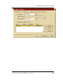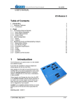
1
QuickStart Instructions PowerPC Kit phyCORE-MPC5554 Using iSYSTEM winIDEA for PowerPC Development Tool Chain Note: The PHYTEC Tool-CD includes the electronic version of the phyCORE-MPC5554 English Hardware Manual Edition: January 2013 A product of a PHYTEC Technology Holding company phyCORE-MPC5554 QuickStart Instructions In this manual are descriptions for copyrighted products that are not explicitly indicated as such. The absence of the trademark () and copyright () symbols does not imply that a product is not protected. Additionally, registered patents and trademarks are similarly not expressly indicated in this manual. The information in this document has been carefully checked and is believed to be entirely reliable. However, PHYTEC Messtechnik GmbH assumes no responsibility for any inaccuracies. PHYTEC Messtechnik GmbH neither gives any guarantee nor accepts any liability whatsoever for consequential damages resulting from the use of this manual or its associated product. PHYTEC Messtechnik GmbH reserves the right to alter the information contained herein without prior notification and accepts no responsibility for any damages which might result. Additionally, PHYTEC Messtechnik GmbH offers no guarantee nor accepts any liability for damages arising from the improper usage or improper installation of the hardware or software. PHYTEC Messtechnik GmbH further reserves the right to alter the layout and/or design of the hardware without prior notification and accepts no liability for doing so. Copyright 2013 PHYTEC Messtechnik GmbH, D-55129 Mainz. Rights - including those of translation, reprint, broadcast, photomechanical or similar reproduction and storage or processing in computer systems, in whole or in part - are reserved. No reproduction may occur without the express written consent from PHYTEC Messtechnik GmbH. Address: EUROPE NORTH AMERICA PHYTEC Messtechnik GmbH Robert-Koch-Str. 39 D-55129 Mainz GERMANY PHYTEC America LLC 203 Parfitt Way SW, Suite G100 Bainbridge Island, WA 98110 USA Ordering +49 (6131) 9221-32 Information: [email protected] 1 (800) 278-9913 [email protected] Technical Support: +49 (6131) 9221-31 [email protected] 1 (800) 278-9913 [email protected] Fax: +49 (6131) 9221-33 1 (206) 780-9135 Web Site: http://www.phytec.eu http://www.phytec.com 2nd Edition: January 2013 2 © PHYTEC Messtechnik GmbH 2013 L-695e_2 Table of Contents 1 Introduction to the phyCORE-MPC5554 Rapid Development Kit5 1.1 Rapid Development Kit Documentation ...................................... 5 1.2 Overview of this QuickStart Instruction ...................................... 6 1.3 System Requirements ................................................................... 6 1.4 The PHYTEC phyCORE-MPC5554 ........................................... 8 1.5 The iSYSTEM winIDEA Development Tool Chain ................. 12 2 Getting Started .................................................................................. 22 2.1 Installing Rapid Development Kit Software .............................. 22 2.2 Installing the iSYSTEM winIDEA Tool Chain ......................... 23 2.3 Connecting the iONE-E to your Host-PC .................................. 28 2.4 Interfacing the phyCORE-MPC5554 to your Host-PC ............. 32 2.5 Downloading Example Code with winIDEA IDE ..................... 35 2.5.1 2.5.2 Running the Hello Demo Project in external RAM ...... 38 Running the Hello Demo Project in MPC5554 On-Chip Flash .............................................................................. 48 2.5.3 Running the Hello Demo Project in external Flash ...... 53 2.6 iSYSTEM Background Information and Troubleshooting. ...... 56 2.5.1 External Flash setup (***). ............................................... 58 2.5.2 Speed-up Flash process for external Flash devices........... 64 2.5.3 Plug-ins for winIDEA. ...................................................... 66 2.5.4 Consider your new, own applications. .............................. 66 Index of Figures Figure 1: iSYSTEM winIDEA IDE Architecture i.e. with iC5000......... 15 Figure 2: View of Development Board and Jumper Settings .................. 33 Figure 3: Connecting the Supply Voltage at X5 ..................................... 34 © PHYTEC Meßtechnik GmbH 2013 L-695e_2 3 phyCORE-MPC5554 QuickStart Instructions 4 © PHYTEC Messtechnik GmbH 2013 L-695e_2 Introduction 1 Introduction to the phyCORE-MPC5554 Rapid Development Kit This QuickStart provides: General information on the PHYTEC phyCORE-MPC5554 System on Module. An overview of iSYSTEM AG winIDEA GNU development tool chain. Instructions on how to run example programs on the phyCORE-MPC5554, mounted on the PHYTEC Development Board, in conjunction with iSYSTEM winIDEA tools. Please refer to the phyCORE-MPC5554 Hardware Manual for specific information on such board-level features as jumper configuration, memory mapping and pin layout. Selecting the links on the electronic version of this document links to the applicable section of the phyCORE-MPC5554 Hardware Manual. 1.1 Rapid Development Kit Documentation This "Rapid Development Kit" includes the following electronic documentation on the enclosed "PHYTEC Tool-CD-ROM": PHYTEC phyCORE-MPC5554 Hardware Manual PHYTEC phyCORE-MPC5554 QuickStart Instructions MPC5554 controller User's Manuals and Data Sheets © PHYTEC Meßtechnik GmbH 2013 L-695e_2 5 phyCORE-MPC5554 QuickStart Instructions 1.2 Overview of this QuickStart Instruction This QuickStart Instruction provides a general "Rapid Development Kit" description, as well as software installation hints and example programs enabling quick out-of-the box start-up of the phyCORE-MPC5554 in conjunction with iSYSTEM winIDEA tools. It is structured as follows: 1) The "Getting Started" section uses the example program "Hello" to demonstrate the download of user code to the phyCOREMPC5554 external RAM and Flash memory using iSYSTEM' winIDEA Debugger. 1.3 System Requirements Use of this "QuickStart" requires: the PHYTEC phyCORE-MPC5554 the PHYTEC Development Board with the included DB-9 serial cable and AC adapter supplying 5 VDC/min. 1000 mA the iSYSTEM iONE-E Emulator unit (or other iSYSTEM Debugger unit you own). iONE-E is the hardware interface between a standard PC USB 1.1 port and the standard (2.54 mm) 14-pin MPC55xx JTAG/ONCE On-Chip-Debug header connector the PHYTEC phyCORE-MPC5554 Tool CD-ROM including winIDEA Setup Files for iONE-E computer with 800 MHz Pentium compatible microprocessor, 512 MB RAM, CD-ROM drive, USB port, serial, and Ethernet ports, running Windows XP/2000, 350 MB free hard disk space plus project space 6 © PHYTEC Messtechnik GmbH 2013 L-695e_2 Introduction For more information and example updates, please refer to the following sources: http://www.phytec.com - or - http://www.phytec.eu [email protected] - or - [email protected] http://www.isystem.com [email protected] [email protected] [email protected] (Field-Application D-A-CH) http://www.freescale.com © PHYTEC Meßtechnik GmbH 2013 L-695e_2 7 phyCORE-MPC5554 QuickStart Instructions 1.4 The PHYTEC phyCORE-MPC5554 The phyCORE-MPC5554 module integrates the 32-bit Freescale MPC5554 PowerPC microcontroller on an advanced PCB layout. All applicable controller signals extend to two 200-pin, high-density Molex connectors. In addition to the on-chip memory (2 MByte high speed Flash, 64 kByte SRAM, 32 kByte Cache), the phyCOREMPC5554 can be populated with 2 MByte to 8 MByte Standard Flash memories (29LV800..320) and 1 MByte to 16 MByte of Sync. BurstSRAM. The external Flash supports direct on-board programming without additional programming voltages. A serial EEPROM, 4 Kbyte (up to 32 KByte), is available for storing operating parameters. I2C Real-Time Clock with a calendar and alarm function serves as a real-time reference. The phyCORE-MPC5554 is especially suited for applications requiring processing of calculation-intensive algorithms in addition for handling of numerous complex and time critical external signals. The MPC5554's integrated Signal Processing Extension (SPE) provides DSP-like hardware-level execution of elementary operations with single precision floating point numbers (FPU) and supports Multiply and Accumulate operations with its MAC unit. The two Enhanced Time Processing Units (eTPU) with its 32 channels (signals) each provides flexible co-processing to meet hard real-time requirements. In addition of the processors processing units, the SOM integrates a very high density FPGA device, which enables a very flexible way to generate the application specific interface needs. Interfaces like PCI bus, normal address/data bus, GPIO, LVDS ports etc. can be implemented by software. This FPGA can accommodate additional co-processing and periphery units like I2C-Master Controller, 1-Wire-Bus Controller etc. Other controller features supported by the SOM include three on-chip CAN 2.0B controllers, two UARTs; SPI Interface, PWM Ports and 40 channel Dual-ADC. 8 © PHYTEC Messtechnik GmbH 2013 L-695e_2 Introduction phyCORE-MPC5554 Technical Highlights System On Module in subminiature form factor (84 x 57 mm) according to phyCORE specifications all applicable controller and other logic signals extend to two highdensity 200-pin Molex connectors processor: Freescale embedded PowerPC MPC5554 (up to 132 MHz clock) Internal Features of the MPC5554: 32-bit PowerPC core, up to 132 MHz CPU speed 32 kByte Cache Memory SPE Signal Processing Extention (FPU, MAC Unit) MMU Memory Management Unit DMA Direct Memory Access Controller Interrupt Latency <70ns @132MHz 64 kByte SRAM; 32kByte capable of battery buffering 2 MByte Flash (read while write functionality) two UART’s (eSCI) LIN support four SPI interfaces (DSPI) three CAN 2.0B interfaces two TPU Time Processing Units with 32 channels (pins) each 24 channels (pins) Timer system (eMIOS) for PWM etc. dual 12-bit ADC with 40 (65) channels (ext. MUX) multi-purpose I/O signals JTAG/ONCE/NEXUS/Nexus test/debug port © PHYTEC Meßtechnik GmbH 2013 L-695e_2 9 phyCORE-MPC5554 QuickStart Instructions Memory Configuration 1 : SRAM: 1 MByte to 16 MByte flow-through synchronous burstRAM, 32-bit access, 0 wait states, 2-1-1-1 burst mode Flash-ROM: 2 MByte to 8 MByte asynchronous standard FlashEEPROM, 32-bit access I2C Memory: 4 kByte EEPROM (up to 32 kByte, alternatively I2C FRAM, I2C SRAM) Other Board-Level Features: UART: two RS-232 transceivers for channel A and B (RxD/TxD); also configurable as TTL CAN: two CAN transceivers 82C250-compatible for channels A and B; also configurable as TTL Ethernet: 10/100 Mbit/s LAN91C111 FPGA: Lattice XP FPGA XP6/10/15 or XP20 device for IP cores: e.g. I2C-Master, 1-Wire-Master, UART, SPI etc. Programmable bus bridge (simple address-/data bus, PCI-Bus, DDR-RAM etc.) 84 external GPIO with programmable characteristics (TTL, CMOS, differential logic, LVDS etc.) Application specific control logic and clock generation (PLL) Embedded memory: Single-/Dualport SRAM, FIFO etc. In-system programmable over JTAG-Emulation I2C Real-Time Clock with calendar and alarm function JTAG/JTAG/ONCE/NEXUS/Nexus test/debug port industrial temperature range (-40…+85C) 1: 10 Please contact PHYTEC for more information about additional module configurations. © PHYTEC Messtechnik GmbH 2013 L-695e_2 Introduction phyCORE-MPC5554 Development Board The phyCORE-MPC5554 Development Board is fully equipped with all mechanical and electrical components necessary for the speedy and secure insertion and subsequent programming of the phyCORE-MPC5554 module with high-density (0.635 mm pitch) pin header connectors. RS-232 and CAN interface signals extend from the module to dual-stacked DB-9 connectors on the Development Board, while the Ethernet signals extend to a RJ-45 connector. Two debugging connectors are provided. A reduced 14-pin JTAG/OnCE and a full 38-pin JTAG/OnCE/Nexus connector. Development Board Technical Highlights Development Board (160 x 100 mm) high-density (0.635 pitch) Molex connector for speedy and secure insertion, and subsequent programming, of the phyCOREMPC5554 System On Module socket for +5VDC power supply connectivity 2x RS-232 at DB-9 sockets 2x CAN interfaces at DB-9 plugs RJ-45 Ethernet interfaces 10-pin JTAG header to the FPGA device 14-pin OnCE/JTAG/Nexus interface 38-pin OnCE/JTAG/Nexus interface two power LEDs for monitoring the supply voltages RESET and IRQ push buttons Expansion Bus: all signals routed from implemented phyCORE module to 2 x 200-pin Molex connectors, enabling connectivity to PHYTEC Add-On hardware © PHYTEC Meßtechnik GmbH 2013 L-695e_2 11 phyCORE-MPC5554 QuickStart Instructions 1.5 The iSYSTEM winIDEA Development Tool Chain The iSYSTEM winIDEA itself is a highly functional Integrated Development Environment (IDE) tool for developers to create, compile, assemble and link optimized embedded systems code for the PowerPC and many other architectures. The winIDEA works together with included or your own GNU CC package or ANY common third party Compiler (like i.e. DIAB-Data/Wind-River, Greenhills, Freescale etc.) and other useful tools (like i.e. EasyCode, Tessy, National Instruments LabView etc.). There are interfaces via "isystem.connect" to any Windows based application includes your own PC applications, Excel and others. After building the code winIDEA has a powerful debug control center with target download and flash programming possibilities together with the iSYSTEM Emulator hardware. For On-Chip debugging this could be an "iC5000" universal On-Chip Debug unit with NEXUS Trace, other iSYSTEM Debugger for MPC5xxx or the attached, limited "iONE-E" connected. The iSYSTEM winIDEA Integrated Development Environment (IDE) is quite similar to the PC market leader "Microsoft Visual Studio" with extensions and changes for embedded developing and debugging. That IDE is intuitive, easy to use and work in a cohesive manner regardless of compiler or target architecture. This means you can reach more markets and solve more problems faster without invest time and money for learning how new different tools work or work together. iSYSTEM winIDEA IDE graphical interface includes an editor, project manager, class browser, universal command line based compiler interface, source-level and assembly-level debugger. In addition to keeping all your development tools a mouse-click away, the IDE stores compiler, project, Window and debug settings and tracks all the dependencies for your project, simplifying even the most complex development build. The software debugging in winIDEA are state-of-the art and features syntax highlighting of sources and the power to evaluate structures, complex expressions and such things in the debugger. You may correct/change/add source code within the 12 © PHYTEC Messtechnik GmbH 2013 L-695e_2 Introduction build-in Editor while debugging your application. You are able to perform Multi-Core (i.e. eTPU C-Source Level) debugging. With iC5000 you would be able to Debug and use the famous NEXUS Trace possibilities. Now you get a brief overview, please refer the details in the following documents - stored in the winIDEA program directory - after installing winIDEA. Partly they are available as on-line help too. To start with your works please follow instructions in sector 2.4. The important documents for you regarding winIDEA are: winIDEA.pdf This is the universal reference and user manual OCD MPC5500.pdf (refer ...\DOC directory and subdir) This is the special manual for MPC55xx [**] IONE123_10.pdf This is the description of your iONE [**] [**] this should be attached to your iONE-E in printed form iSYSTEM winIDEA consists of the IDE with interfaces to other tools and the Debugger, which are structured as follows: IDE: Windows-based Integrated Development Environment housing the following tools in one IDE: Project &Build Manager: it shows the collection of groups, its files and support files necessary and used to build a target loadable output file, invokes the assembler, compiler and linker, pass error messages to the build-in Editor. It interfaces to external make utilities too with lot of possibilities. © PHYTEC Meßtechnik GmbH 2013 L-695e_2 13 phyCORE-MPC5554 QuickStart Instructions Editor: double-clicking on a file in the Project Manager Window opens that file in the Editor. C compiler: GNU Standard compiler package included (*) Debugger: Fully active source-level and assembly-level Windows-based debugger for iSYSTEM Debug hardware (*) You can adapt own GNU or other common compilers. You may edit your sources with your favorite editor outside of winIDEA too winIDEA then automatically reload the changed sources. Upon installation of winIDEA - please select "full" installation - , the executables and all manuals, documents, further examples and GNU Compilers are located in the C:\iSYSTEM\winIDEA\2012\ folder (selectable). The GNU CC tools are then located at ..\gcc\ppc\. There you will find the GNU Documentation too (..\doc\). All tool commands are easily accessible via intuitive pull-down menus with prompted selections. The winIDEA handling itself has mostly self-describing user Interface. You have three ways for dealing with it: Hot-Keys (re-attachable under "Tools => Customize") Icons (Buttons for mouse - simply place mouse over it and wait for function explanation) Use "right mouse key" for context sensitive local menus. It makes a difference whether you do it in the middle of a Window or at the margin for example, simply try it out! As depicted on Figure 1, winIDEA’s editor, Project/Build manager with connected C/C++ compiler and linker and winIDEA debugger with flash programming possibilities comprise the complete tool chain. You have - configurable - Windows and Window panes for your project, internal editor, disassembly and CPU main registers, global watches and real-time refreshed watches, local variables and 14 © PHYTEC Messtechnik GmbH 2013 L-695e_2 Introduction context, build manager and search output, memory contents and special-function registers and toolbars for the main functionality. Figure 1: iSYSTEM winIDEA IDE Architecture i.e. with iC5000 Please note that you will have no Trace, Profiler or Code Coverage with simple iONE-E - you would need an iC5000. Please ask iSYSTEM directly for a free test run before the trial period end! As depicted on Figure 1, winIDEA’s editor, Project/Build manager with connected C/C++ compiler and linker and winIDEA debugger with flash programming possibilities comprise the complete tool chain. You have - configurable - Windows and Window panes for your project, internal editor, disassembly and CPU main registers, global watches and real-time refreshed watches, local variables and context, build manager and search output, memory contents and special-function registers and toolbars for the main functionality. All IDE commands and functions are accessible via pull-down menus, most of it with short cuts too. All colors and custom key sets for the whole winIDEA parts/Windows can be user-defined. © PHYTEC Meßtechnik GmbH 2013 L-695e_2 15 phyCORE-MPC5554 QuickStart Instructions The integrated Editor is a fair and easy-to-use tool to compose and later debug the source code. It includes a context-sensitive coloring of keywords for easy navigation and recognition. Pop-up menus provide an overview of all available functions and navigation to the start of a desired function or its corresponding header file. The search engine enables location of a specified text string within file or within project (scope selectable) and implements find-and-replace operations. At the left selection margin you will find rectangle blocks after download your application code into the target via winIDEA debug hardware. If the compiler has build MCU executable code from that line, there exist the rectangle there. So you can easily control your compiler and source constructs and partly the optimizing of your compiler. But you can do even more. You can select (right mouse key in editor, options…) which function your left mouse key has, when it is above selection margin (Line select, set/reset break or run until). In addition the margin display your Break status (active/ not active) in the source and - with the iSYSTEM Trace tools or Emulators - you get Execution coverage Info's there. It is a multi-file, multi Window editor and every Window within winIDEA can arranged as "docked" or "MDE" or "Mini Frame". With that we support i.e. a very useful second screen on your Windows PC. There is an interface to common Source Control Systems. Anyway: Please refer the manuals for details! If you prefer an other, more powerful Editor (i.e. "Context" as powerful freeware or ECLIPSE as complete Build System or Editor only), the winIDEA Editor will load and synchronize automatically the results of your work. The Build System controls the Project dependencies automatically and invokes the different C/C++ compilers, assemblers, linkers, code converters and many other tools for "perfect" build. After download your results to the target winIDEA automatically recognize any of your changes in a project file (source, headers, …) and will ask you whether you want to "make" new version or continue (i.e. if only comment changed) the debugging. If you agree, winIDEA can do all the necessary things (compile, link, download/flash to the target, run until…) automatically WITHOUT closing the debug session. This depends from your settings in winIDEA. 16 © PHYTEC Messtechnik GmbH 2013 L-695e_2 Introduction For syntax check, winIDEA provides pre-processing of single source file. It will update dependencies too. The Linker result is a *.elf file and - via converter or direct - i.e. Freescale S-record output file format could be available too. The winIDEA can download and handle all usual output formats, but only ELF contains the necessary Debug information! So you don't need other files for download usually. And you need normally neither different files for debug and flashing nor other tools for flashing - it is "all in one" tool! For PPC is this preset (compare the examples and GNU Documentation) ELF Format with winIDEA download file option "load program headers physical" (not "sections only"!). The WinIDEA Debugger provides C/C++ (and ADA for some CPU's) source-level, assembly-level and mixed mode debugging. The eTPU's of MPC5554 are supported (refer "Debug => Core" menu). For code exploration, absolute or conditional breakpoints can be accessed or single-step operation can be performed. Step-over, stepinto and step-out of code function capabilities are provided. The contents of usual HLL constructs (i.e. arrays, enums, pointers, structs …) can be displayed in different kinds, monitored and contents and kind of presentation manually modified. There exist different global watches, global real-time watches and local variables display Windows including context (= Call-Stack). For internal Flash only it provides unlimited flash breaks for Code. Be careful, this can worn your number of possible flash cycles for that Chip (check Freescale manual for information). A flash-break within internal Flash read, erase and re-program up to 3 times the smallest possible flash-sector for every break (worst case; if active, reached and then continued execution afterwards). winIDEA SDK/Scripting via isystem.connect. Besides IDE functionality you are able to use Scripting. Please refer i.e. to "c:\iSYSTEM\winIDEA\2012\sdk", in example for PHYTON script © PHYTEC Meßtechnik GmbH 2013 L-695e_2 17 phyCORE-MPC5554 QuickStart Instructions "c:\iSYSTEM\winIDEA\2012\sdk\iSYSTEM.Python.SDK\examples\" directory. We recommend using PHYTON if you are inexperienced user because it is free of charge, there exists good community support and lot of extensions via WEB. It is usable directly from winIDEA IDE (beside this the free "PYSCRIPTER" GUI for Python strongly recommended for do the JOB as Python development and execution system!). iSYSTEM have build a lot of useful examples (*.py) in the corresponding directory for you. With installation of winIDEA we add an iSYSTEM library to Standard PYTHON (today Python 2.7 - if you don't have it we install it before) and then you can use everything nicely. If you prefer other supported Script languages (C#, Pearl, …) we provide some examples too, but you have take care for installations on your own. In case of questions please ask [email protected] because Python Scripts open a lot of additional, very useful possibilities for you daily work. It can not be described here. iSYSTEM testIDEA unit test. Note that any winIDEA contains a basic unit-test feature, called "testIDEA" (needs PYTHON installed). You may invoke it from menu and it opens - after a while - a second IDE (testIDEA GUI) for setup and executes the testcases. Please use the testIDEA internal HelpSystem to collect more information about. You will find additional information on www.isystem.com. If you are forced to think about automatized tests this could be a very interesting solution - i.e. together with Scripting! iSYSTEM winIDEA iONE-E supports the following debug options of the phyCORE-MPC5554 target. 18 A hardware-level debugging is provided via a USB 1.1 PC-toiONE-E and from that to target connection using the MPC5554 JTAG/OnCE port (OnCE: on-chip emulation). The OnCE itself is a kind of hardware debug module integrated on the processor from Freescale. © PHYTEC Messtechnik GmbH 2013 L-695e_2 Introduction You may download/program/edit the content of the internal MCU flash, the internal RAM, the external RAM and external Flash on PHYTEC MPC5554 Kit with it. Please note that you maybe have to change the external Flash device within this particular example for external Flash because there could be different devices soldered on your target. The term "download" means in parallel "initialize debugging tool" too. So with no preceding "download" after power on you usually cannot debug. If your code within flash is unchanged at startup, you may use Icon "load symbols only" and winIDEA "Reset button" instead for saving time of extra download. But usually your debugging starts with first download of actual Code wherever it will be placed/loaded. The MCU itself at download time is not initialsized in any way (refer to Freescale manual BAM/boot assist module!). So if download target is external Flash or RAM device winIDEA have to use a *.ini file. This is provided and setup correctly within the corresponding PHYTEC examples if you change something or try to use own constructs you should be aware of this MCU, project and target related settings and how to get the setup into Debugger! Please note that there exists no real iSYSTEM MCU Simulator (only a plug-in for the core…) for this MPC5xxx architecture at all, so you need always your PHYTEC Kit or other target for debugging your application code. To the iSYSTEM winIDEA the following debug parts could be connected: iONE-E This is the small blue box you got with the package. It is an entry level debug tool with following characteristics: Run up to 90 days AFTER FIRST DOWNLOAD without restriction with any common compiler output. So you are able to try different commercial Compilers - mostly 30 day versions are usual. You could if you want - compare delivered standard GNU solution results against commercial Compiler. Their result will be "Standard *.ELF files" too only with Green-Hills you have to set the Compiler option "dual_debug" to get this standardised output. © PHYTEC Meßtechnik GmbH 2013 L-695e_2 19 phyCORE-MPC5554 QuickStart Instructions The Nexus Trace Port with Profiler, Code-Coverage, Trace and eTPU Trace is NOT supported with iONE-E solution - for this features exists the iSYSTEM "iC5000" unit. The iONE-E has only USB connection to the PC (USB 1.1 low speed standard, could be connected on any USB Port) and the device itself is powered over the USB line from the Host-PC. The support for iONE-E is limited to usual warranty and technical function together with the package. In case of questions beside that please ask for, we will find an agreement to support you. For the Demo-Workspaces and target PHYTEC is your primary support partner, but you may ask [email protected] directly for questions regarding debugging too. After that 90 day trial period, iONE-E’s download code-size is limited to 32 Kbyte! You should ask iSYSTEM at latest after this period for a test-run (up to additional 4 weeks) with the "real" Debug Tools, i. e. "iC5000". iC5000. This is the latest, universal On-Chip Debug & Trace unit for nearly unlimited high-speed and high-end debugging and optional using of NEXUS and ETM Trace-Port technic. It contain a powerful Freescale MPC CPU and Data transfer from/to the PC is very fast (up to 300 times faster then iONE-E) via USB 2.0 high-speed (480 Mbit/sec) and/or Ethernet 100 connection. Because of latest FPGA technic inside the Box is always the same. New MCU family or architecture support is only an additionally cheap adapter for the physical connection and a cheap license for Debugging and maybe for the Trace-Port. The NEXUS Trace of MPC5554 allows you to trace and debug both eTPU's beside the usual Code debug & trace with that kind of units. If you get this iC5000 tool for evaluation you will find the Demo workspaces with the same name, but "iC5000_" before. In Example: iONE-E Workspace is "hello_ExtFlash.xjrf", the same Workspace for iC5000 is named "iC5000_hello_ExtFlash.xjrf". It contains a prerecorded trace so you could have a look what NEXUS Trace could do. To use this please ask iSYSTEM FAE Holger Wild via eMail for further instructions ([email protected]). 20 © PHYTEC Messtechnik GmbH 2013 L-695e_2 Introduction iC3000. If you own a (older) "iC3000" based Debug unit there are iCARD's available for Debugging of the MPC 5xxx MCU's On-ChipDebug too. In addition for iC3000 you could have an iTRACE GT as high-end tool for the NEXUS trace possibilities. © PHYTEC Meßtechnik GmbH 2013 L-695e_2 21 phyCORE-MPC5554 QuickStart Instructions 2 Getting Started What you will learn with this Getting Started example: installing the Rapid Development Kit software installing iSYSTEM winIDEA toolchain interfacing the phyCORE-MPC5554, mounted on the Development Board, to a host-PC connect the iONE-E to the PC USB, set the path to the USB drivers in the winIDEA directory (see below) downloading example user code to the phyCORE-MPC5554 external memory programming example user code to the MPC5554 On-Chip Flash memory, external SRAM or external Flash memory 2.1 Installing Rapid Development Kit Software Insert the PHYTEC phyCORE-MPC5554 Tool-CD into the CDROM drive of your host-PC. The CD should automatically launch a setup program that installs the required demos, documentation and other support documents. Otherwise the setup program setup.exe can be manually executed from the root folder of the PHYTEC Tool-CD. The default destination location is C:\PHYTEC. All path and file statements within this QuickStart Instruction are based on the assumption that you choose the default install paths and drives. If you decide to choose different paths and/or drives you must consider this for all further file and path statements. We recommend that you accept the default destination location. Follow the instructions in the setup Window. 22 © PHYTEC Messtechnik GmbH 2013 L-695e_2 Suggestions for Improvement 2.2 Installing the iSYSTEM winIDEA Tool Chain The applicable WinIDEA tool chain software must be installed BEFORE you connect the included iONE-E to any USB Port of your host-PC in order to ensure successful completion of this QuickStart Instruction! Failure to install the proper software could lead to possible version conflicts, resulting in functional problems. winIDEA 2012 needs PYTHON version 2.7.3. It is included in the installation file, but it will not ask for the destination location. Instead it will always use the default C:\Phython27\. If you want it to be installed to another path, you need get PYTHON 2.7.3 installation file from the web and install it before installing winIDEA 2012. Install the iSYSTEM winIDEA tool chain via Windows Explorer from a single file named "winIDEA2012_68.exe". You will find it on the CD within directory “winIDEA 2012”. For installing you need Administrator rights! © PHYTEC Meßtechnik GmbH 2013 L-695e_2 23 phyCORE-MPC5554 QuickStart Instructions At first you should get this screen. 24 © PHYTEC Messtechnik GmbH 2013 L-695e_2 Suggestions for Improvement Choose at least the installing options above (or mark all of them). The default destination location is suggested during installation, i.e. C:\iSYSTEM\winIDEA\2012\ All path and file statements within this QuickStart Instruction are based on the assumption that you accept the default install paths and drives. If you choose different paths and/or drives you must consider this for all further file and path statements. We recommend that you accept the default destination location and install all options, including PYTHON Version 2.7.3 (default is C:\Python27\). In this example case PYHTON was installed before seperatly to a different location. © PHYTEC Meßtechnik GmbH 2013 L-695e_2 25 phyCORE-MPC5554 QuickStart Instructions After pressing "Install" the installation continues like depicted above with the usual "advance" screens. If an older version of Phyton has been found on your PC, it will first be removed. 26 © PHYTEC Messtechnik GmbH 2013 L-695e_2 Suggestions for Improvement After that the new one will be installed. Thereafter standard installations continues. © PHYTEC Meßtechnik GmbH 2013 L-695e_2 27 phyCORE-MPC5554 QuickStart Instructions This part should end with this screen. Please click "Finish". 2.3 Connecting the iONE-E to your Host-PC After having winIDEA Software successfully installed, connect the included iONE-E to any USB Port of your host-PC. Windows will recognize it and ask for drivers. Installation should work if you select “automatically”. The drivers are usually NOT Microsoft verified, but they work and are compatible to any actual updated Windows version. In case Windows asks for certificated driver, you should answer something like "use it anyway". 28 © PHYTEC Messtechnik GmbH 2013 L-695e_2 Suggestions for Improvement In case of difficulties with that please ask [email protected] for latest drivers and advice because the iSYSTEM iONE-E is a special product build only for PHYTEC and will not be tested with every winIDEA Version and Windows Version! Please note that you have unfortunately to repeat this procedure for every USB port connection of your PC, if you connect iONE-E (or any other iONE, iC5000, etc.) for the first time to that port. This is a Windows request and unfortunately we cannot change this behavior. USB Setup after connection of iONE-E (in winIDEA it is called iTAG USB). Sorry for German dialogs, but these windows depend on the language of Windows-PC and are similar for every supported Windows language. In case that Windows asks you for searching for updates over the internet, please answer “No!”. In case that it didn't find the driver, you may take a look here (German XP, probably different when using other Windows versions): "C:\Dokumente und Einstellungen\All Users\isystem\drivers\ ". © PHYTEC Meßtechnik GmbH 2013 L-695e_2 29 phyCORE-MPC5554 QuickStart Instructions You will find "InstallDriver.exe" there that could solve issues. If you are not limited from your IT department (you should ask there!) the free tool "USBDeView" (www.nirsoft.net) could solve nearly any USB related trouble. Simply "deinstall" awkward device and reinstall correspondig driver to get it work (of course: here no warranty!). Please choose "automatic installation". 30 © PHYTEC Messtechnik GmbH 2013 L-695e_2 Suggestions for Improvement When you get this window, your system is ready to work. © PHYTEC Meßtechnik GmbH 2013 L-695e_2 31 phyCORE-MPC5554 QuickStart Instructions 2.4 Interfacing the phyCORE-MPC5554 to your Host-PC Connecting the phyCORE-MPC5554, mounted on the PHYTEC Development Board, to your computer is simple: If the phyCORE module (part # PCM-028-xxxx) is not already mounted on the Development Board (part # PCM-979), please mount it pins-down onto the Development Board's receptacle footprint (X1) as shown in Figure 2 below. Ensure that pin 1 of module matches pin 1 of the receptacle on the Development Board. Ensure that there is a solid connection between the module's pins and the Development Board receptacle. If the phyCORE module is removed from the Development Board, take precautions to properly mount the module when it is reattached to the Development Board. Pin 1 on the phyCORE module (denoted by the hash stencil mark on the PCB) should be matched to the footprint receptacle on the Development Board marked by "X1" on the PCB. Also take precautions not to damage the connectors when the phyCORE is removed from and inserted onto the Development Board. Configure the jumpers on the phyCORE Development Board as indicated in Figure 2. This correctly routes the CAN interface signals. Please see the phyCORE-MPC5554 Hardware Manual for further information on jumper settings. 32 © PHYTEC Messtechnik GmbH 2013 L-695e_2 Figure 2: © PHYTEC Meßtechnik GmbH 2013 Ethernet 10/100 MBit Power Input +5V L-695e_2 D6 L6 +5V regulated D9 D10 5V Boot MemorySelection 1+2 external Flash 2+3 internal Flash 3V3 X1A X1C X1D PHYTEC 1241.0 X2 MPC5554 JTAG/OnCE MPC5554 JTAG/OnCE/Nexus FPGA JTAG D8 1 Reset IRQ Suggestions for Improvement View of Development Board and Jumper Settings 33 MPC5554 Nexus-Port phyCORE-MPC5554 QuickStart Instructions Connect the iONE-E JTAG/OnCE interface cable to the 14-pin JTAG/OnCE header on the Development Board at X3. This connection is used for the communication between the iONE-E and the phyCORE-MPC5554 target hardware. Connect the included serial cable to the lower socket P2A of the female double DB-9 connector on the Development Board and to a free serial port of your host-PC. This will enable you to monitor board-host communication via the terminal emulation Window included in the winIDEA surface or a terminal emulation program, such as Windows HyperTerminal. Using the included 5VDC power adapter to connect the power socket X5 on the board (refer to Figure 3 for the correct polarity). The phyCORE module/Development Board combination requires a 5 VDC@1A ±5 % regulated supply. Polarity: +5 VDC 5% 1000 mA -- + Center Hole 2.1 mm 5.5 mm GND Figure 3: Connecting the Supply Voltage at X5 The LED’s D9 and D10 (two green LED’s) should light, indicating that all voltages are supplied to the phyCORE module. D9 indicates the +5V supplied by the attached power supply and D10 monitors the on-board regulated 3V3. The phyCORE-MPC5554 should now be properly connected via the Development Board to the host-PC and power supply and you are now ready to use the iSYSTEM winIDEA tool chain to establish communication. This phyCORE module/Development Board combination shall also be referred to as "target hardware" or simply "target". 34 © PHYTEC Messtechnik GmbH 2013 L-695e_2 Suggestions for Improvement 2.5 Downloading Example Code with winIDEA IDE At first please note that later within this manual you will find a chapter “Background information & Troubleshooting”. In case of trouble please refer to there. If you followed the suggested defaults during installation, you will find some examples here: C:\PHYTEC\PCM-028 phyCORE-MPC5554\PowerPC-Kit iSystem\ Quickstart\Demos\Hello Please note that in case that you want to create your own new project later on, we strongly suggest to copy one of these examples to a new directory and then modify it. You should not use the "Workspace new" option within winIDEA! It would generate a complete empty project without ANY necessary settings, so you probably will “get lost". Concept of winIDEA is always to deal with a “Workspace”. It consists out of XML-files named *.xjrf and *.xqrf, which together (!) represent the Workspace with all important settings for project build, download to desired destination, debug, breakpoint and Window/pane positions as well as particular setup. A Workspace contains only one project. Settings like fonts, font colours and last opened Workspace are stored in your Windows log-in profile within file winIDEA.xtrf. Usually this file is stored in an hidden directory. The *.lcf is the Linker command file (it is an ascii text file). The *.ini file (ascii text file) is needed because of special MCU issues and downloads to external Flash/RAM. Check the MCU manual regarding "BAM" (Boot assist module), boot behavior and possibilities, "MMU" and "EBI" (external Bus Interface) if you need to know more. Don't worry about that at this time. Our © PHYTEC Meßtechnik GmbH 2013 L-695e_2 35 phyCORE-MPC5554 QuickStart Instructions little Demo Projects will make you familiar with the toolchain and MCU. Later on, you can expand these examples in order to learn more about the powerful PHYTEC MCU Kit without need to change the Linker settings or the INI File. Only keep in mind that the *.ini file ensures that correct and desired application RESET-entry-point is reached. For your own applications you need to understand and to setup the BAM first. Otherwise your target will only work correctly when debugger is connected and in use! For these example applications entry points are setup in the last lines within corresponding *.ini files (here last line is active): ### // ==> Reset entry according to lcf // R PC L 0x00000008 // application Entry internal Flash // R PC L 0x20000008 // application Entry external Flash R PC L 0x21000008 // application Entry external RAM ### The Hello example sends a program to the target hardware that, when executed, sends a character string from the RDK back to the host-PC. The character string can be viewed with the terminal emulation Window in the winIDEA or with a terminal emulation program. The program also controls the user LED D6 (red LED) with equal on and off ratio. To show how to load and run software, the Hello Demo exists in three different versions for the delivered iONE-E (the "iC5000_* are for iC5000 Debug Tool only!): Hello_ExtRAM.xjrf Running the Hello Demo Project in external SRAM. This application cannot run as "stand alone" (without Debugger connected) because SRAM is volatile Memory. You can expect the fastest execution because RAM needs no wait states during code execution. 36 © PHYTEC Messtechnik GmbH 2013 L-695e_2 Suggestions for Improvement Hello_IntFLASH.xjrf Running the Hello Demo Project in MPC5554 on-chip Flash. This application could - when flashed - run as "stand alone" too. Jumper 1 on Baseboard needs to be set accordingly. Hello_ExtFLASH.xjrf Running the Hello Demo Project in external Flash memory. This application could - when flashed - run as "stand alone" too. Jumper 1 on Baseboard needs to be set accordingly, different from IntFlash Demo. © PHYTEC Meßtechnik GmbH 2013 L-695e_2 37 phyCORE-MPC5554 QuickStart Instructions 2.5.1 Running the Hello Demo Project in external RAM In this section you will download the Hello Demo to the external Sync. Burst Mode SRAM. Launch the iSYSTEM winIDEA by double-clicking the winIDEA icon or by selecting winIDEA IDE from within the winIDEA program group. Escape from the workspace selection window. Select File | Workspace \ Open Workspace from the winIDEA menu bar. Navigate to C:\PHYTEC\PCM-028 phyCOREMPC5554\ PowerPC-Kit iSystem\Quickstart\Demos\Hello\ExtRAM and open the project file Hello_ExtRAM.xjrf. The Hello_ExtRAM.xjrf project will open with a predefined Window arrangement. 38 © PHYTEC Messtechnik GmbH 2013 L-695e_2 Suggestions for Improvement On the left side you should see the docked Window "project workspace". Ensure that you select "project" and not "symbols" pane there (symbols pane could be interesting later during debugging). Alternatively you can open the demo by browsing to the Hello_ExtRAM.xjrf file with Windows Explorer or another File Manager tool. Double-click to invoke the winIDEA with the demo project. Perform the build process by clicking the Make icon at the tool bar or select Project | Make from the winIDEA pull-down menu (or press F7 key in standard-setting). The Make process generates - if no error occurs - an actual output binary (hello.elf) in subdirectory /DEBUG/ of the project Workspace directory. The "OUTPUT" build/search status Window will appear within winIDEA while the project is being compiled and linked. You should/may close it if no error occurs, otherwise you can navigate (right mouse key => "Error" in local menu or simply press function key "F4") to your source file errors. Note that origin linker errors and any build message appear in the output Window pane Tools. Start the download process by clicking the download icon at the tool bar (or press key combination Ctrl+F3). If this will rise an error "Error 40: Communication port not found", then please refer to troubleshooting section. On the first download ever with iONE-E it asks to start the evaluation period. You have to select "yes" for continue and with that you start the iONE-E evaluation period (90 days) automatically. © PHYTEC Meßtechnik GmbH 2013 L-695e_2 39 phyCORE-MPC5554 QuickStart Instructions Thereafter you will be reminded as countdown for the remaining days of using with the full featured Debug tool on every Debug session. In this example the download is performed to the external RAM. The appropriated target initialization for the debugger to reach the RAM and execute from it are in the *.ini file contained in the project folder. The following status Window will appear during the download and should look similar when successful (you may uncheck "close when finished" during download to verify it without precipitance). 40 © PHYTEC Messtechnik GmbH 2013 L-695e_2 Suggestions for Improvement Once download is complete, the source code Window will show the actual location of the program counter from where to start the software execution (green bar in disassembly Window above). In the high level language Window this location is marked with a arrow on left margin. The exact occurrence depends on your setup the screen dumps here are changed for better visibility! You may change this in every Window with right mouse key => options. The high level language Window shows at the moment also assembler code due to the entry point of the project is located in a startup file that is written in assembler code. Because GNU CC creates "HLL Line Info" for assembler too you see on the left margin of Source Window rectangles. Later you will see this again within C Source for every line which was translated to MCU instructions. So it is easy to follow the way from C-Source (or C++) to executable Object Code and within the Disassembly Window of winIDEA you have a display in "mixed mode". The next step will run the code to the main() function because there is a breakpoint set (active). © PHYTEC Meßtechnik GmbH 2013 L-695e_2 41 phyCORE-MPC5554 QuickStart Instructions Run the code by clicking on the icon or press F5. This will execute the startup code and the processor is running until the first breakpoint is reached. Now the processor has stopped at the breakpoint before the InitBoard() function. Breakpoints can be placed by setting the focus to a code line and pressing F9 (or press right mouse key and select corresponding entry from local menu!). The grey shaded area left the code line will then filled red (colours may differ and could be changed). Pressing F9 again remove the breakpoint. Before running the complete demo like described, we need a terminal Window to show the output that will send over the serial port A (connector P2A at the development board; refer to section 2.4). If not already opened as "floating Window" (again: right mouse key within Windows for "local menu" and you may i. e. change the "Window type"): Open and configure the "Terminal Window" of the winIDEA by selecting View|Terminal over the menu bar or click to the icon. 42 © PHYTEC Messtechnik GmbH 2013 L-695e_2 Suggestions for Improvement within the terminal For configuration open the Options Icon Window and select the corresponding Host PC serial port number. You are not limited to COM1 (default) to COM4, simple overwrite the selection field (i.e. COM7) instead of pull down selection. © PHYTEC Meßtechnik GmbH 2013 L-695e_2 43 phyCORE-MPC5554 QuickStart Instructions Press the Configure button adjust the Baud Rate to 9600 and set other settings like depicted below. Close the Configure Window and Options Window by confirming with the OK button. To establish the serial port communication press the Connect button within the Terminal Window icon bar. With a successful opened port the Connect Icon disappears and the status in the right corner changes to CONNECTED. Run the code by clicking on the icon or press F5. This will restart the code execution beginning with the InitBoard() function 44 © PHYTEC Messtechnik GmbH 2013 L-695e_2 Suggestions for Improvement with full processor speed. The status of the processor is shown in the lower right corner of the winIDEA Window. It is now changed from STOP to RUN and Terminal Window starts display like Function "main()" is located at external RAM address depicted above. © PHYTEC Meßtechnik GmbH 2013 L-695e_2 45 phyCORE-MPC5554 QuickStart Instructions In the Terminal Window you can see some status messages and the output of a second counter. Also see the User LED D6 located on the baseboard between the Ethernet plug and the Expansion Bus Connector. The LED changes once a second. The watch Window shows some pre-defined Real-time Watches. The debugger communicates via the JTAG/OnCE module of the Processor and use the "Real-time-watch" Feature. This allows reading of global variables contents without remarkable influence of the MCU (compare Freescale manual). Note the sec_tick variable. This variable is incremented in the demo once a second dependent on the emiosCh0Ctr counter variable that is incremented by an interrupt service routine once a millisecond. Important remark: 46 © PHYTEC Messtechnik GmbH 2013 L-695e_2 Suggestions for Improvement The projects are build with Compiler optimize setting "-O0" which means "no optimize" at all. If you change this Compiler optimization level it could happen that important parts of source code will be ignored for translation and application misbehaves if you not use "volatile" keyword accordingly! For the GNU CC there are different optimize levels (0,1,2,3,s at least - refer GCC manual) and it is set [here -O0] within menu "Project - Settings, pane Compiler". © PHYTEC Meßtechnik GmbH 2013 L-695e_2 47 phyCORE-MPC5554 QuickStart Instructions 2.5.2 Running the Hello Demo Project in MPC5554 On-Chip Flash In this section you will download and program the Hello Demo to the MPC5554 on-chip Flash memory. Make sure Jumper JP1 on the phyCORE-MPC5554 Development Board is closed at position 2+3 (refer to Figure 2). Open the Hello_IntFLASH.xjrf and build the output file hello.elf as described in section 2.5.1. To program the hello.elf to the internal processor Flash perform a download by selecting the icon or press Ctrl+F3. winIDEA automatically first erase and then burns the binary to the internal CPU Flash during download process. Verify is performed on-the-fly while flashing and - if set like above - as a extra compare file : flash content after all. Above "close when (successful) finished" was unchecked to take the screen shot). 48 © PHYTEC Messtechnik GmbH 2013 L-695e_2 Suggestions for Improvement But you may use additionally a extra verify procedure by selecting Debug | Verify Download from the main menu bar at any time you like. This feature of winIDEA compares again the Download File with its target address area in the memory and your progress picture should look like this (usually check "Close when finished if any Error here this Window remains open) It is independent of the memory type and will work for ROM or RAM. Note that winIDEA is able to change directly the Content of any kind of RAM content and internal Flash (i.e. patch Code or change Constants is possible with that feature). You have now successfully downloaded and burned the Hello example program to the MPC5554 on-chip Flash memory. The next steps are to start the Hello application with the debugger or use it stand-alone. © PHYTEC Meßtechnik GmbH 2013 L-695e_2 49 phyCORE-MPC5554 QuickStart Instructions Running the "Hello" with the Debugger After download/burn procedure the processor is stopped at the first code instruction (if not set to other desired options within winIDEA Debug/Download File/options). Prior executing the hello demo code the processor runs its internal BAM (Boot Assist Module) code. This code starts at physical address 0xFFFFFFFC, pre-initializes the processor and reads the first two 32-bit words (see crt0.s file) from flash address 0x00000000. The first 32-bit word code contains a boot identifier and the second is the start address (0x00000008) of the application ("hello" demo). After finishing the BAM processor part branches to that address and would run the application code. 50 © PHYTEC Messtechnik GmbH 2013 L-695e_2 Suggestions for Improvement But for your comfort we use the INI File too, in this case Execution Point is set to 0x00000008 at the end of INI file to avoid that confusingly (but correct) BAM-Start disassembly Window picture above after RESET/Download. If you want really see this origin MCU behavior (important to know for own and/or stand-alone projects!) disable using INI File (attempt only for that internal Flash Demo please) in winIDEA Hardware => Emulation Options => Initialization (see next picture), change from "Init sequence" to "none". You can change it back at every time to get it comfortable again. If you build own applications they have to run - after successful debugging period - always without any INI File or they would not run without Debug tool. © PHYTEC Meßtechnik GmbH 2013 L-695e_2 51 phyCORE-MPC5554 QuickStart Instructions Anyway: To start the execution click on the icon or press F5. This and the following are the same procedures as described in the previous section. Stand-alone running Check that jumper JP1 on the baseboard is configured to 2+3 (refer to Figure 2) and press the reset button S2 near the double DB9 serial connector. The system will re-start out of the on-chip Flash memory. Or re-connect the power supply cable to X5. The target performs automatically an power-on reset and starts the hello application out of the on-chip internal Flash. 52 © PHYTEC Messtechnik GmbH 2013 L-695e_2 Suggestions for Improvement 2.5.3 Running the Hello Demo Project in external Flash In this section you will download program the Hello Demo to external Flash memory and will execute it from there. Using external Flash memory for program execution, development and parameter storage have some advantages compare to limited internal MCU flash. The size of external Flash device could be very much bigger (important for RTOS, Graphics, complex protocols i.e.). It could usually cover very much more re-flash cycles before getting worn out. It could be used/mixed together with the internal Flash (i.e. internal Flash for startup the system and basic routines, external Flash used for big applications). Now we want to look on it for program execution. Make sure Jumper JP2 on the phyCORE-MPC5554 Development Board is closed at position 1+2 (refer to Figure 2). Open the Hello_ExtFLASH.xjrf and build the output file hello.elf as described in section 2.5.1. (***) Because PHYTEC has different Flash types soldered in different sizes please check FIRST which kind of flash are mounted (usually two decives for covering the 32bit bus with 16bit-wide each) before continue! To change this default setting in winIDEA please refer to External Flash setup on Section 2.5. If you verified the correct external Flash type set there you may continue here with the comfortable, easy way. Standard 2012 is this kind of flash type, the bold one is setup in the Example. 2MB phyCORE Modul (Flash-1, 2x IM615: S29AL008J70BFI010) 8MB phyCORE Modul (Flash-3, 2x IM435: S29AL032D90BFI030) Easy way: Simply press usual winIDEA Download key. Because of the setting it loads the application fist (Debug Info). Then it invokes the winIDEA external Flash part automatically. This looks like depicted on next page. Please be patient, it takes about 78 seconds (41 sec. i.e. for iC5000) total to finish the Flash process for external flash. © PHYTEC Meßtechnik GmbH 2013 L-695e_2 53 phyCORE-MPC5554 QuickStart Instructions 54 © PHYTEC Messtechnik GmbH 2013 L-695e_2 Suggestions for Improvement How this works? It reads configuration from Menu Flash/Program and Download File setting, combine it and use the stored information to - configure the external Flash type (***) - use download file and its information, load first the Debug info - erase the contents (in this case only involved sectors) ext. Flash - program the application code inside the external Flash - verify it - and return & continue to usual download part for downloading the symbol information close the Flash Program Window. You have now successfully downloaded and burned the Hello example program to the external Flash memory. The next steps are to start the Hello application with the debugger or use it stand-alone. Running the Hello with the Debugger First click to the Download Icon to initialize the project for debugging. Then run the code by clicking on the Run Icon or press F5. This will execute the startup code (crt0.s) and the processor is running until the first breakpoint is reached near the InitBoard() function in main.c. Press again F5 to go ahead with code execution. Now you can see the output in the terminal Window and the blinking LED as in the previous sections. Stand-alone running Check that jumper JP1 on the baseboard is configured to 1+2 (refer to Figure 2) and press the reset button S2 near the double DB9 serial connector. The system will re-start out of the external Flash memory. Or re-connect the power supply cable to X5. The target performs automatically an power-on reset and starts the hello © PHYTEC Meßtechnik GmbH 2013 L-695e_2 55 phyCORE-MPC5554 QuickStart Instructions application out of the external Flash. Address reported is 0x200000E0 for function "main()" in that case. 2.6 iSYSTEM Background Information and Troubleshooting. If "Error 40: Communication port not found" rise with new Debug device at beginning, then please select Hardware \ Hardware… from the winIDEA menu bar, navigate to pane Communication and clear content of field Device. Leave this field blank and press the "Test" button. Now PC and iONE-E exchange Data packages. If this works fine, then you can connect any iONE-E to that Workspace. Reason is, that the winIDEA and the blue iONE-box tightly coupled. With that feature you could connect several boxes on same PC to different winIDEA - i.e. for Multi-Processing. 56 © PHYTEC Messtechnik GmbH 2013 L-695e_2 Suggestions for Improvement Clicking on Button Test should show a working USB-connection now. Click close and ok to return to winIDEA main Window and click the download icon again. It should work now. "Hardware not found" // Communication Error // Freeze If you have this kind of "Communication Error" or "Hardware not found" messages during your work simply disconnect and reconnect the iONE-E from USB Cable, but let it off for about 5 seconds. Because iONE-E is only a Debugger for Evaluation purpose it has neither RESET key nor complex Hardware inside. So like all simple tools with no external power supply it could be, that it "hangs up" or winIDEA freeze. Disconnect, wait short and re-connect solve these problems. If Debugger hang up constantly repeatable with your own or changed sample projects but work with the described, unchanged examples, it could be that your application code is wrong linked. Download to "nowhere" or out of boundaries and jump to it usually cause that kind of trouble. To verify your project you could analyse the *.MAP file (build from the Compiler, in the Examples you find it under "Linker Files" in Project Workspace Window of winIDEA. © PHYTEC Meßtechnik GmbH 2013 L-695e_2 57 phyCORE-MPC5554 QuickStart Instructions You may take a look in those cases without using target with the winIDEA "Demo Mode" (Hardware - Demo Mode). In that case the neither physical iONE-E nor target is used (you have to switch off automated external Flash download), but implemented loader load your Application into PC RAM. There you may expect it, including disassembling. But again: This is NOT a Simulator, so stepping or so is impossible. Don’t forget to uncheck the "Demo Mode" afterwards for continue with normal Target debugging with iONE-E! 2.5.1 External Flash setup (***). To setup & program the hello.elf "manually" to the external Flash open the Flash Programmer Window by selecting Flash | Setup from the main menu bar of the winIDEA. 58 © PHYTEC Messtechnik GmbH 2013 L-695e_2 Suggestions for Improvement Check the pane "Device" and compare with your physically soldered device on the Target. Above you find an overview as example. "Word (16bit)" is usually correct if - like here - are different possibilities. If necessary please © PHYTEC Meßtechnik GmbH 2013 L-695e_2 59 phyCORE-MPC5554 QuickStart Instructions change ONLY here. If you don't find your corresponding device please write this to Support ([email protected]), but add the description of that missed device. If you don't like the "automated" process described in external Flash example or if you want to do more complex things winIDEA can do that. So you could have one file for external Flash, other for internal Flash and a File with Parameters for RAM. In that case "automatic" cannot do this. So uncheck the "Use Debug download files" within FLASH Programming setup first. Change to pane "Download Files" within FLASH Programming setup. Add your desired file(s) there. This will be flashed to the external Flash. 60 © PHYTEC Messtechnik GmbH 2013 L-695e_2 Suggestions for Improvement You can see that here only CODE without Debug info will be stored into external Flash. © PHYTEC Meßtechnik GmbH 2013 L-695e_2 61 phyCORE-MPC5554 QuickStart Instructions In case of part of the application code you have to add that download file within menu Debug - files for Download Download files, but change properties to only "Load Symbols" there! If content of external Flash does not change often it is a good idea to flash external content manually. Because dealing with external Flash on simple iONE-E is performed via JTAG Port of MCU OCD only and with the USB 1.1 Low Speed (1.5 Mbit/s) connection this takes a very long time (i.e. 90 seconds her for the example). With iC5000 i.e. with its Hi-Speed (480 Mbit/s) it is possible to use a "UMI Monitor" and block operations instead of byte-after-byte. This would dramatically lower the flash-time consumption for external Flash. For invoke the flash process always manually change "Auto program Flash" option within FLASH programming setup screen to "never". 62 © PHYTEC Messtechnik GmbH 2013 L-695e_2 Suggestions for Improvement Then you may select "Program" from FLASH menu. It should depict "connected" or the setup is wrong. Now you are able to perform the flash process by pressing "Start" button or do it step-by-step with the corresponding buttons on left side of that Window. This is very useful in case of trouble for investigations. For "daily" development process which using external Flash device it is more convenient to invoke the flash programming prior the debugger Initialize/Download procedure automatically. This is the reason why example was set in that way. © PHYTEC Meßtechnik GmbH 2013 L-695e_2 63 phyCORE-MPC5554 QuickStart Instructions Anyway the Window after flash process should looks like this successful procedure. 2.5.2 Speed-up Flash process for external Flash devices Programming of external Flash from Debugger via JTAG (OCD) Debug Port only is usually very slow. Reason is that only the MCU "under debug" has access to those external devices via its external Bus system and it takes a lot of time to program "Byte after Byte". This procedure could be improved if a "Flash Monitor" application would build and executed in MCU RAM. It acts like a standard application, operate block oriented and could handle "verify on the fly" (immediately compare Flash content with internal block buffer after buffer is programmed). It would be possible - if MCU have 64 © PHYTEC Messtechnik GmbH 2013 L-695e_2 Suggestions for Improvement enough RAM for it - that this small program handles everything, including speed up MCU (max. SysClk), initialize Bus system, set correct amount of wait-states and so on. The "Flash Monitor" will be loaded from the Debugger into the RAM of target MCU and then Debugger starts its execution. With certain state variables there is a handshake and communication so Debugger will send the Data for target external flash in blocks. The "Flash Monitor" speeds up the whole process, but there are some drawbacks. (Today it is not existing for PHYTEC kit, sorry) It must be build for every external flash device and it has to consider different kind of connection (byte, word, 1, 2 or more devices) from the external Flash devices to the MCU Bus. This must repetitive for every MCU - and there are different MCU's with different size of internal RAM (not always enough for a good Job!). In case of NAND Flash devices it gets additional target specific and more complicated. There is reason for customers using in most cases a RTOS to deal with usual "SD" Storage Flash Cards and their complex File System. This in total is a lot of effort and Tool vendors could not do it "by the way" without extra charge, not at once and immediately "perfect". He would need a target, best way is a loan of customers target to develop, build and improve that "Flash Monitor". Because iSYSTEM AG has more than 27 years experience in this quick market they provide a free-of-charge "do it yourself" solution for experienced developers. If this not fit the expectations iSYSTEM could do all that tasks above for extra charge NRE. If you performed a "Standard installation" like suggested you could take a look into "UMI SDK" (universal monitor interface) of winIDEA. You will find documentation and briefly examples here: "c:\iSYSTEM\winIDEA\2012\sdk\iSYSTEM.UMI.SDK\Documen tation\UMI.pdf" Like personal experiences - of course not transferable without restrictions - user could expect about 5 times faster flash process for external Flash, maybe better. © PHYTEC Meßtechnik GmbH 2013 L-695e_2 65 phyCORE-MPC5554 QuickStart Instructions 2.5.3 Plug-ins for winIDEA. winIDEA provide a plug-in Interface and you are able to write additional own plug-ins (compare again the "SDK" Section of your winIDEA installation directory) For the MPC5554 exist possibilities to see more MCU internals. This is i.e. important for dealing with MCU Caches. Some of plug-ins are for your comfort, like "run duration" (this is not comparable with measurement with the precise NEXUS trace, only a simple counter for time!). You could add own plug-ins - see \SDK. This is the "TLB" table This is MMU Inspector plug-in. You find a "table walk" within menu winIDEA - Debug. 2.5.4 Consider your new, own applications. As you learned in the past chapters and the hardware manual you have to pay attention for some prerequisites if you build an own 66 © PHYTEC Messtechnik GmbH 2013 L-695e_2 Suggestions for Improvement working application. We will give you a quick overview to important items to avoid usual, MCU related pitfalls especially if you come from another MCU, i.e. older one or 8 bit. This is a common overview, not special for the MPC55xx only and not detailed! eTPU. iSYSTEM Tools could support both eTPU's of MPC5554 for debugging of Assembler and C (with iC5000 Trace possible too!). For building Code for eTPU you have to use and buy a special C-Compiler (Ashware/Bytecraft). In case of questions please send an eMail to [email protected]. First of all the "ancient" MCU's were "ready to work" after poweron and cold-start reset. Today MCU are equipped with ECC RAM. Before using it you have to write to every address to set the ECC bit correctly or you will get an error (Job of "ctrs.s", but check and be aware of it). Next are you have to deal correctly with MMU (and maybe MPU) because some MCU's has only partly access to the Flash (i.e. 4 Kbyte instead of 2 MByte after Reset). This should be again covered by "ctrs.s" code, but not always comprehensive because these startup files are usually universal. Please check the Freescale Application Notes, i.e. AN2865 and for better understanding AN4239. Note that you have not only ramp-up the PLL from Crystal Clock to reach maximum MCU performance. You have to enable the MCU Caches for Code-Execution and/or Data access. Don't expect that peripherals (like CAN) are ready to use. Because of lowering the Power consumption nearly all latest MCU's don't power this part nor connect SysClock to it after Reset. Your applications have to take care of it. Especially Debugger gets in trouble just with item before. If you imagine that you work on Monday, initialize the SFR i.e. for CAN and leave the SFR Window open. You open winIDEA again on Tuesday and after download the Disassembly window point to "se_illegal" command. Single step fails in that case. What's happened? Because your application is not started yet the CAN is © PHYTEC Meßtechnik GmbH 2013 L-695e_2 67 phyCORE-MPC5554 QuickStart Instructions nor powered neither clocked. But because SFR Window is left open, winIDEA have to readout this and the MCU quite immediately with trap and point to "se_illegal" instruction. To avoid that scenario you should close this kind of windows before next attempt, repeat the download, start application and re-open the Window later. Alternatively you may write/extend an INI File that attaches the CAN on the internal power and clock before download. Then everything works fine. In final application you don't use Debugger and your program starts immediately. Then everything runs fine without Code change. There are other possibilities to reach that goal (Python Script, Reset & Run for certain time before stopping application…) but you should aware of those issues. Testing application without Bootloader - example. As you learned in chapters before you may setup execution point within INI file. Alternatively PYTHON Script would to the Job too - automate the whole process: Download, set maybe break, patch variables automatically for test purpose, execute from different address…. If you have no Bootloader ready but need to write Code for it you may use winIDEA for change the Entry point - i. e. execute from different location than MCU usually do. For that you may set a Register PC (and/or other Registers/SFR's) within "Initialization after Download". In the example below Application starts always from 0x00000008. 68 © PHYTEC Messtechnik GmbH 2013 L-695e_2 Suggestions for Improvement © PHYTEC Meßtechnik GmbH 2013 L-695e_2 69 phyCORE-MPC5554 QuickStart Instructions Document: phyCORE-MPC5554 QuickStart Instructions Document number: L-695e_2, January 2013 How would you improve this manual? Did you find any mistakes in this manual? Page Submitted by: Customer number: Name: Company: Address: Return to: PHYTEC Technologie Holding AG Postfach 100403 D-55135 Mainz, Germany Fax : +49 (6131) 9221-26 70 © PHYTEC Messtechnik GmbH 2013 L-695e_2 Suggestions for Improvement PHYTEC Meßtechnik GmbH 2013 L-695e_2