1
HP Moonshot Switch
User and Maintenance Guide
Abstract
This document is for the person who installs, administers, services, and troubleshoots switches. This guide provides identification, setup, installation,
and removal procedures. HP assumes you are qualified in these areas.
Part Number: 723317-002
December 2013
Edition: 2
© Copyright 2013 Hewlett-Packard Development Company, L.P.
The information contained herein is subject to change without notice. The only warranties for HP products and services are set forth in the express
warranty statements accompanying such products and services. Nothing herein should be construed as constituting an additional warranty. HP shall
not be liable for technical or editorial errors or omissions contained herein.
Contents
Component and LED identification .................................................................................................. 5
Chassis front panel LEDs and buttons ........................................................................................................... 5
Moonshot-6SFP Uplink Module .................................................................................................................... 6
Uplink module components ............................................................................................................... 6
Uplink module buttons and LEDs ........................................................................................................ 6
Moonshot-4QSFP+ Uplink Module ............................................................................................................... 7
Uplink module components ............................................................................................................... 7
Uplink module buttons and LEDs ........................................................................................................ 8
Moonshot-45G Switch Module .................................................................................................................... 9
Switch module button, sensor, and LEDs ............................................................................................. 9
Moonshot-180G Switch Module ................................................................................................................ 10
Switch module button, sensor, and LEDs ........................................................................................... 10
iLO CM management port ........................................................................................................................ 11
Operations................................................................................................................................. 12
Extend the chassis from the rack ................................................................................................................ 12
Remove the access panel.......................................................................................................................... 13
Open the cable management arm ............................................................................................................. 14
Remove the uplink module blank ............................................................................................................... 14
Remove the switch module blank ............................................................................................................... 15
Setup......................................................................................................................................... 16
Installation information and guidelines ....................................................................................................... 16
Uplink module bays ................................................................................................................................. 17
Installing the uplink module ....................................................................................................................... 17
Installing the switch module ...................................................................................................................... 18
Configuration ............................................................................................................................. 21
Configuring the switch ............................................................................................................................. 21
Network mapping ................................................................................................................................... 22
Production network mapping........................................................................................................... 22
Management network mapping ....................................................................................................... 23
Interfaces ............................................................................................................................................... 23
Moonshot-6SFP uplink interfaces ...................................................................................................... 23
Moonshot-4QSFP+ uplink interfaces ................................................................................................. 24
Moonshot-45G downlink interfaces .................................................................................................. 25
Moonshot-180G downlink interfaces ................................................................................................ 26
Command Line Interface ........................................................................................................................... 27
Connect to the switch console ......................................................................................................... 27
Access the CLI locally ..................................................................................................................... 27
Obtaining the switch management IP address ................................................................................... 28
Configure the Enable password ....................................................................................................... 28
Interacting with the switch from the iLO CM firmware ......................................................................... 28
Firmware................................................................................................................................................ 30
Update the switch firmware ............................................................................................................ 30
Updating the switch firmware using the switch console ....................................................................... 30
Troubleshooting .......................................................................................................................... 32
Contents
3
Troubleshooting resources ........................................................................................................................ 32
Illustrated parts catalog ............................................................................................................... 33
Customer self repair................................................................................................................................. 33
Parts only warranty service ....................................................................................................................... 33
Switch customer self repair components...................................................................................................... 34
Removal and replacement procedures ........................................................................................... 35
Removing the switch module ..................................................................................................................... 35
Removing the uplink module ..................................................................................................................... 35
Regulatory information ................................................................................................................ 37
Safety and regulatory compliance ............................................................................................................. 37
Turkey RoHS material content declaration ................................................................................................... 37
Ukraine RoHS material content declaration ................................................................................................. 37
Warranty information .............................................................................................................................. 37
Electrostatic discharge ................................................................................................................. 38
Preventing electrostatic discharge .............................................................................................................. 38
Grounding methods to prevent electrostatic discharge .................................................................................. 38
Specifications ......................................................................................................................................... 39
Chassis environmental specifications ................................................................................................ 39
Chassis specifications .................................................................................................................... 39
Support and other resources ........................................................................................................ 40
Before you contact HP.............................................................................................................................. 40
HP contact information ............................................................................................................................. 40
Acronyms and abbreviations ........................................................................................................ 41
Documentation feedback ............................................................................................................. 43
Index ......................................................................................................................................... 44
Contents
4
Component and LED identification
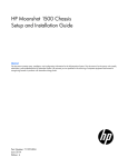
Chassis front panel LEDs and buttons
Item
Description
LED Status
1
Chassis power LED
Flashing Green = The chassis is waiting to power on.
Green = Normal operation
Amber = Standby operation
Off = No power
2
Chassis health LED
Green = Normal operation
Flashing Amber = Degraded condition
Flashing Red = Critical condition
Off = No power
3
Chassis UID LED/button
Blue = Chassis ID is selected.
Flashing blue = System firmware update is in process.
Off = Chassis ID is not selected.
4
Cartridge health LEDs
Green = Normal operation
Amber = Standby mode
Flashing Amber = Degraded condition
Flashing Amber (All) = Moonshot 1500 CM module is not installed.
Flashing Red = Critical condition
Off = Cartridge is not installed or no power exists.
5
Switch module A health
LED
Green = Normal operation
Flashing Amber = Degraded condition
Flashing Red = Critical condition
Off = Switch module is not installed or no power exists.
6
Switch module B health
LED
Green = Normal operation
Flashing Amber = Degraded condition
Flashing Red = Critical condition
Off = Switch module is not installed or no power exists.
Component and LED identification 5
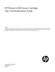
Moonshot-6SFP Uplink Module
Uplink module components
Item
Component
Description
1
Serial console port
For management
2
SFP+ ports X1–X6
1Gb or 10Gb Ethernet
SFP+ ports X1 through X6 support Ethernet traffic only.
SFP+ ports support the following pluggable Ethernet transceiver modules:
•
HP 1000BASE-T SFP
•
HP 10GBASE-SR SFP+
•
HP 10GBASE-DAC SFP+
Any available port can be used to connect to the data center. Ensure the port is populated with supported HP
transceiver modules that are compatible with the data center port type.
Uplink module buttons and LEDs
Component and LED identification 6
Item
Description
Status
1
Uplink module UID
LED/button
Solid blue = Switch module ID is selected.
Flashing blue = Switch module firmware
update is in progress.
Off = Switch module ID is not selected.
2
Uplink module health Green = Normal operation
LED
Flashing amber = Degraded condition
Flashing red = Critical condition
Off = No power
3
Uplink module link
LED
Solid green = Link
Off = No link
4
Uplink module
activity LED
Flashing green = Activity
Off = No activity
5
Reset button
Resets the switch module
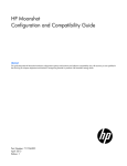
Moonshot-4QSFP+ Uplink Module
Uplink module components
Item
Component
Description
1
Serial console port
For management
2
QSFP+ ports Q1–Q4
40Gb Ethernet
QSFP+ ports Q1 through Q4 support Ethernet traffic only.
QSFP+ ports support the following pluggable Ethernet transceiver modules:
•
HP 40GBASE QSFP+
•
HP 40GBASE QSFP+ SR4
•
HP 40GBASE QSFP+ DAC
•
HP 40GBASE QSFP+ to 4x10G SFP+
Any available port can be used to connect to the data center. Ensure the port is populated with supported HP
transceiver modules that are compatible with the data center port type.
Component and LED identification 7
Uplink module buttons and LEDs
Item
Description
Status
1
Uplink module UID
LED/button
Solid blue = Switch module ID is selected.
Flashing blue = Switch module firmware
update is in progress.
Off = Switch module ID is not selected.
2
Uplink module health Green = Normal operation
LED
Flashing amber = Degraded condition
Flashing red = Critical condition
Off = No power
3
Uplink module link
LED
Solid green = Link
Off = No link
4
Uplink module
activity LED
Flashing green = Activity
Off = No activity
5
Reset button
Resets the switch module
Component and LED identification 8
Moonshot-45G Switch Module
Switch module button, sensor, and LEDs
Item
Description
Status
1
Switch module power Green = Normal operation
LED
Amber = Standby operation
Off = No power
2
Switch module health Green = Normal operation
LED
Flashing amber = Degraded condition
Flashing red = Critical condition
Off = No power
3
Switch module uplink Green = Link
activity LED
Flashing green = Activity
Off = No activity
4
Switch module
Green = Link
downlink activity LED Flashing green = Activity
Off = No activity
5
Switch module UID
LED/button
Solid blue = Switch module ID is selected.
Flashing blue = Switch module firmware
update is in progress.
Off = Switch module ID is not selected.
6
Access panel sensor
Detects the presence of the access panel*
*The fan speed adjusts automatically when the access panel is installed or removed.
Component and LED identification 9
Moonshot-180G Switch Module
Switch module button, sensor, and LEDs
Item
Description
Status
1
Switch module power Green = Normal operation
LED
Amber = Standby operation
Off = No power
2
Switch module health Green = Normal operation
LED
Flashing amber = Degraded condition
Flashing red = Critical condition
Off = No power
3
Switch module uplink Green = Link
activity LED
Flashing green = Activity
Off = No activity
4
Switch module
Green = Link
downlink activity LED Flashing green = Activity
Off = No activity
5
Switch module UID
LED/button
Solid blue = Switch module ID is selected.
Flashing blue = Switch module firmware
update is in progress.
Off = Switch module ID is not selected.
6
Access panel sensor
Detects the presence of the access panel*
*The fan speed adjusts automatically when the access panel is installed or removed.
Component and LED identification 10
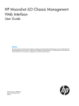
iLO CM management port
The iLO CM management port provides communication with the switch service port interface and is used for
remote sessions. All service port traffic is routed through the iLO/MGMT port, located on the iLO CM module:
The switch service port interface is enabled by default and can be used with the switch serial console port
when making configuration changes.
The switch serial console port is on the uplink module. To identify the switch serial console port, see uplink
module components (on page 7, on page 6).
To find the switch service port IP address for remote management, see "Obtaining the switch management IP
address (on page 28)."
Component and LED identification 11
Operations
Extend the chassis from the rack
1.
Pull down the quick release levers on each side of the chassis.
2.
Extend the chassis from the rack until it locks once.
3.
Press the push tab on the rail, and then fully extend the chassis.
WARNING: To reduce the risk of personal injury or equipment damage, be sure that the rack is
adequately stabilized before extending a component from the rack.
4.
After performing the installation or maintenance procedure, slide the chassis back into the rack, and
then press the chassis firmly into the rack to secure it in place.
WARNING: To reduce the risk of personal injury, be careful when pressing the server rail-release
latches and sliding the server into the rack. The sliding rails could pinch your fingers.
Operations
12
Remove the access panel
IMPORTANT: After performing a procedure inside the chassis, always install the access panel on
the chassis when complete. Do not operate the chassis for long periods of time with the access
panel removed.
1.
Release the access panel latch.
2.
Slide the access panel back about 1.5 cm (0.5 in).
3.
Lift and remove the access panel.
Operations
13
NOTE: Turn the access panel over to locate the hood labels. These labels provide information on
installing various options, flexible memory configurations, LED status indicators, and switch
settings.
Open the cable management arm
To open, lift the cable management arm up as you swing it open.
Remove the uplink module blank
Remove the component as indicated.
Operations
14
Remove the switch module blank
Remove the component as indicated.
Operations
15
Setup
Installation information and guidelines
Before installing the module, review the following:
•
Always install the switch module and the uplink module in corresponding bays. Both components must
be installed for normal operation.
•
The switch module and the uplink module can be installed in any order.
•
The switch module and the uplink module power down when either module is removed from the chassis.
•
The switch module and the uplink module power up after both modules are installed in the chassis.
•
Removing any component from bay A or bay B does not disrupt traffic for the other switch.
•
Always use the recommended firmware version. For current information on recommended firmware
versions, see the HP website (http://www.hp.com/go/moonshot/download).
•
For the most current product information, see the HP Moonshot Information Library
(http://www.hp.com/go/moonshot/docs).
Setup
16
Uplink module bays
The uplink module can be installed in the uplink module bays located in the rear of the chassis.
Installing the uplink module
IMPORTANT: To avoid connectivity loss, do not remove any network cables or uplink modules
already in operation.
1.
Remove the uplink module bay blank.
Setup
17
2.
Prepare the uplink module for installation.
3.
Install the uplink module.
4.
Do one of the following:
o
If the switch module is already installed, verify the uplink module powers on and the health LED is
green.
o
If the switch module is not installed, install the switch module before verifying LEDs.
For more information, see the "Installation information and guidelines (on page 16)."
5.
After both components have been installed, verify the switch firmware is at the recommended firmware
version. For more information, see the HP website (http://www.hp.com/go/moonshot/download).
The installation is complete.
Installing the switch module
CAUTION: To avoid connectivity loss, do not remove switches already in operation.
To install the switch module:
1.
Extend the chassis from the rack (on page 12).
2.
Remove the access panel (on page 13).
Setup
18
3.
Locate the switch module slot and remove the blank.
4.
Prepare the switch module for installation.
Setup
19
5.
Align and install the switch module into the chassis.
6.
Do one of the following:
o
If the uplink module is already installed, verify the switch module powers on and the health LED is
green.
o
If the uplink module is not installed, install the uplink module before verifying LEDs.
For more information, see "Installation information and guidelines (on page 16)."
7.
Install the access panel.
8.
Install the chassis in the rack.
9.
After both components have been installed, verify the switch firmware is at the recommended firmware
version. For more information, see the HP website (http://www.hp.com/go/moonshot/download).
The installation is complete.
Setup
20
Configuration
Configuring the switch
To configure the switch, see the Switch Administrator's Guide and the Switch CLI Command Reference in the
HP Moonshot Information Library (http://www.hp.com/go/moonshot/docs).
Configuration
21
Network mapping
Production network mapping
The first network interface discovered by the operating system routes traffic through switch A. The second
network interface discovered by the operating system routes traffic through switch B.
Configuration
22
Management network mapping
All traffic from the service port management interface is routed through the iLO CM management port (on
page 11).
Interfaces
Interfaces are identified by the switch CLI using a unit/slot/port naming convention.
For more information on interface naming, see the Switch Administrator's Guide and the Switch CLI
Command Reference in the HP Moonshot Information Library (http://www.hp.com/go/moonshot/docs).
Moonshot-6SFP uplink interfaces
Configuration
23
Item
Port
Interface
1
X1
1/1/1
2
X2
1/1/2
3
X3
1/1/3
4
X4
1/1/4
5
X5
1/1/5
6
X6
1/1/6
Interfaces 1/1/1–1/1/6 are the uplink ports that connect to the datacenter.
Moonshot-4QSFP+ uplink interfaces
Item
Port
Portmode
Interface
1
Q1
portmode 1x40G
portmode 4x10G
1/1/1
1/1/2-5
2
Q2
portmode 1x40G
portmode 4x10G
1/1/6
1/1/7-10
3
Q3
portmode 1x40G
portmode 4x10G
1/1/11
1/1/12-15
4
Q4
portmode 1x40G
portmode 4x10G
1/1/16
1/1/17-20
Interfaces 1/1/1–1/1/20 are the uplink ports that connect to the datacenter.
Configuration
24
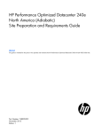
Moonshot-45G downlink interfaces
Interfaces 1/0/1–1/0/45 are the downlinks to the cartridge nodes.
Each SoC is identified as a cartridge node. The iLO CM firmware identifies each node as cxny, where c is
the cartridge and n is the node.
Switch interfaces correspond to cartridge nodes, respectively. For example, c28n1 corresponds to cartridge
28, node 1, and interface 1/0/28.
Configuration
25
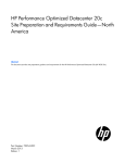
Moonshot-180G downlink interfaces
Interfaces 1/0/1–1/0/180 are the downlinks to the cartridge nodes.
Each SoC is identified as a cartridge node. The iLO CM firmware identifies each node as cxny, where c is
the cartridge and n is the node.
Switch interfaces correspond to cartridge nodes, respectively. For example, c22n3 corresponds to cartridge
22, node 3, and interface 1/0/87:
•
Cartridge 22
o
Node 1 - 1/0/85
o
Node 2 - 1/0/86
o
Node 3 - 1/0/87
o
Node 4 - 1/0/88
Configuration
26
Command Line Interface
Connect to the switch console
To manage the switch, use one of the following ports to connect to the switch console:
•
•
•
•
Service port:
o
Out-of-band management
o
Over TCP/IP
o
Connect through the iLO CM management port ("Obtaining the switch management IP address" on
page 28)
Network port:
o
Inband management
o
Over TCP/IP
o
Connect through the network interface
Serial console port:
o
Out-of-band management
o
Serial
o
Connect to the serial console port ("Access the CLI locally" on page 27)
Virtual serial port:
o
Out-of-band management
o
iLO CM firmware
o
Connect to the virtual serial port from the iLO CM firmware CLI ("Interacting with the switch from the
iLO CM firmware" on page 28)
Consider the following guidelines before managing the switch:
•
A TCP/IP port and a serial port can be in use at the same time.
•
Both TCP/IP ports cannot be in use at the same time.
•
The serial console port and the virtual serial port cannot be in use at the same time.
•
The switch requires a reboot before changing from one serial port to another.
Access the CLI locally
To access the CLI interface locally:
1.
Use a console cable to connect a PC or terminal to the serial console port on the uplink module.
2.
Configure the terminal with the following settings:
o
115200 baud rate
o
8 data bits
o
No parity
o
1 stop bit
Configuration
27
o
3.
No flow control
Start the terminal.
The switch login prompt appears.
4.
Enter: admin
No password is set by default.
Obtaining the switch management IP address
To access the switch console remotely, be sure network connectivity is established with the iLO CM
management port (on page 11).
If DHCP services are provided on the network, obtain the switch management IP address:
1.
Access the switch CLI interface locally.
2.
Enter privileged exec mode. At the switch prompt, enter:
enable
3.
Show the switch management IP address. At the privileged exec prompt, enter:
show serviceport
If DHCP services are not available, configure the serviceport IP address.
Be sure to configure the enable password before managing the switch remotely.
To configure the switch, see the Switch Administrator's Guide and the Switch CLI Command Reference in the
HP Moonshot Information Library (http://www.hp.com/go/moonshot/docs).
Configure the Enable password
The Enable password controls access to the privileged exec mode. The default authentication profile denies
remote access to the privileged exec mode if the Enable password is not configured. Configure the Enable
password before starting a remote session.
To configure the password:
1.
Access the CLI locally (on page 27).
2.
To access the privileged exec mode, enter the following command:
enable
No password prompt appears if a password is not configured.
3.
To configure the Enable password, enter the following command:
enable password {password}
Interacting with the switch from the iLO CM firmware
Use the following iLO CM firmware commands to show switch information, set switch parameters, or connect
to the switch console.
To show switch information:
o
o
o
o
show switch info
show switch list
show switch sn {sa|sb|sa-b}
show switch pid {sa|sb|sa-b}
Configuration
28
o
o
o
show firmware revisions
show switch power
show switch temperature
To set switch power or switch UID LED:
o
o
set switch power {off|on} {sa|sb|sa-b}
set switch uid {off|on} {sa|sb|sa-b}
To connect to the switch console using the virtual serial port:
connect switch vsp {sa|sb}
If the virtual serial port is not configured, configure the virtual serial port before connecting to the switch
console:
1.
2.
Enable VSP:
set switch vsp on {sa|sb}
Reload the switch:
set switch power off {sa|sb}
Traffic is halted on the associated switch.
set switch power on {sa|sb}
For more information on interacting with the switch from the iLO CM firmware, see the HP Moonshot iLO
Chassis Management CLI User Guide in the HP Moonshot Information Library
(http://www.hp.com/go/moonshot/docs).
Configuration
29
Firmware
Update the switch firmware
Switch firmware can be updated using the following CLIs:
•
The iLO CM firmware CLI
•
The switch CLI
To perform updates from the iLO CM firmware CLI, see the HP Moonshot iLO Chassis Management CLI User
Guide in the HP Moonshot Information Library (http://www.hp.com/go/moonshot/docs).
Switch updates are found on the HP Moonshot Component Pack download site
(http://www.hp.com/go/moonshot/download).
Updating the switch firmware using the switch console
Use TFTP, SFTP, or SCP to update the switch firmware using the switch console.
1.
Connect to the switch console.
2.
Log in to the switch.
3.
Enter privileged exec mode:
enable
4.
5.
6.
Verify the version of the current switch image:
show bootvar
Verify connectivity by pinging the file server:
ping x.x.x.x
Copy the firmware image from the file server to the alternate firmware bank of the switch:
copy tftp://x.x.x.x/<path_to_file> alternate
If using SFTP or SCP:
copy {sftp:|scp:}//[email protected]/<path_to_file> alternate
7.
8.
9.
Verify the version of the new switch image:
show bootvar
Configure the switch to boot from the alternate flash file system:
boot system alternate
Reset the switch to boot from the new image:
reload
Traffic is halted on the associated switch. The switch boots from the alternate flash file system. The
image is loaded and runs in the primary flash file system.
10.
11.
12.
Verify the firmware update was successful:
show bootvar
Update the boot loader on the switch:
update bootcode
Update the CPLDs on the switch:
NOTICE: The CPLD update halts network traffic on the associated switch. Once initiated, do not
interrupt the CPLD update. Permanent damage will occur to the switch. CPLD updates may last up
to 10 minutes.
Configuration
30
update cpld
The CPLD update reloads the switch and completes when the switch returns to an operational state. If no
CPLD update is found, the update is not performed.
13.
(Optional) Make a backup of the image:
copy primary alternate
This step overwrites the previous firmware version. Before committing, be sure no plans exist to
downgrade switch firmware.
For more information on updating switch firmware, see the Switch Module Administrator's Guide and the
Switch Module CLI Command Reference in the HP Moonshot Information Library
(http://www.hp.com/go/moonshot/docs).
Configuration
31
Troubleshooting
Troubleshooting resources
The HP Moonshot System Troubleshooting Guide provides procedures for resolving common problems and
comprehensive courses of action for fault isolation and identification, issue resolution, and software
maintenance on the HP Moonshot System. The document is available in the HP Moonshot Information Library
(http://www.hp.com/go/moonshot/docs).
Troubleshooting
32
Illustrated parts catalog
Customer self repair
HP products are designed with many Customer Self Repair (CSR) parts to minimize repair time and allow for
greater flexibility in performing defective parts replacement. If during the diagnosis period HP (or HP service
providers or service partners) identifies that the repair can be accomplished by the use of a CSR part, HP will
ship that part directly to you for replacement. There are two categories of CSR parts:
•
Mandatory—Parts for which customer self repair is mandatory. If you request HP to replace these parts,
you will be charged for the travel and labor costs of this service.
•
Optional—Parts for which customer self repair is optional. These parts are also designed for customer
self repair. If, however, you require that HP replace them for you, there may or may not be additional
charges, depending on the type of warranty service designated for your product.
NOTE: Some HP parts are not designed for customer self repair. In order to satisfy the customer warranty,
HP requires that an authorized service provider replace the part. These parts are identified as "No" in the
Illustrated Parts Catalog.
Based on availability and where geography permits, CSR parts will be shipped for next business day
delivery. Same day or four-hour delivery may be offered at an additional charge where geography permits.
If assistance is required, you can call the HP Technical Support Center and a technician will help you over the
telephone. HP specifies in the materials shipped with a replacement CSR part whether a defective part must
be returned to HP. In cases where it is required to return the defective part to HP, you must ship the defective
part back to HP within a defined period of time, normally five (5) business days. The defective part must be
returned with the associated documentation in the provided shipping material. Failure to return the defective
part may result in HP billing you for the replacement. With a customer self repair, HP will pay all shipping
and part return costs and determine the courier/carrier to be used.
For more information about HP's Customer Self Repair program, contact your local service provider. For the
North American program, refer to the HP website (http://www.hp.com/go/selfrepair).
Parts only warranty service
Your HP Limited Warranty may include a parts only warranty service. Under the terms of parts only warranty
service, HP will provide replacement parts free of charge.
For parts only warranty service, CSR part replacement is mandatory. If you request HP to replace these parts,
you will be charged for the travel and labor costs of this service.
Illustrated parts catalog
33
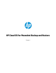
Switch customer self repair components
Item
Description
Spare part number
Customer self repair (on
page 33)
1
HP Moonshot-45G Switch Module
712675-001
Mandatory1
2
HP Moonshot-180G Switch Module
712692-001
Mandatory1
3
HP Moonshot-4QSFP+ Uplink Module
712694-001
Mandatory1
4
HP Moonshot-6SFP Uplink Module
712676-001
Mandatory1
5
Switch module bay blank*
726173-001
Mandatory1
6
Uplink module bay blank*
745288-001
Mandatory1
* Not shown
1
Mandatory—Parts for which customer self repair is mandatory. If you request HP to replace these parts, you will be
charged for the travel and labor costs of this service.
2
Optional—Parts for which customer self repair is optional. These parts are also designed for customer self repair. If,
however, you require that HP replace them for you, there may or may not be additional charges, depending on the type
of warranty service designated for your product.
3
No—Some HP parts are not designed for customer self repair. In order to satisfy the customer warranty, HP requires that
an authorized service provider replace the part. These parts are identified as "No" in the Illustrated Parts Catalog.
Illustrated parts catalog
34
Removal and replacement procedures
Removing the switch module
CAUTION: Be sure to save the running-configuration of the switch before removing any switch
components.
CAUTION: To avoid connectivity loss, do not remove switches already in operation.
CAUTION: For proper cooling, be sure every switch module bay and uplink module bay has either
a blank or a module installed.
To remove the switch module:
1.
Extend the chassis from the rack (on page 12).
2.
Remove the access panel (on page 13).
3.
Locate and remove the switch module.
Removing the uplink module
CAUTION: Be sure to save the running-configuration of the switch before removing any switch
components.
CAUTION: To avoid connectivity loss, do not remove switches already in operation.
Removal and replacement procedures
35
CAUTION: For proper cooling, be sure every switch module bay and uplink module bay has either
a blank or a module installed.
1.
Open the cable management arm (on page 14).
2.
Remove the component as indicated.
Removal and replacement procedures
36
Regulatory information
Safety and regulatory compliance
For safety, environmental, and regulatory information, see Safety and Compliance Information for Server,
Storage, Power, Networking, and Rack Products, available at the HP website
(http://www.hp.com/support/Safety-Compliance-EnterpriseProducts).
Turkey RoHS material content declaration
Ukraine RoHS material content declaration
Warranty information
HP ProLiant and X86 Servers and Options (http://www.hp.com/support/ProLiantServers-Warranties)
HP Enterprise Servers (http://www.hp.com/support/EnterpriseServers-Warranties)
HP Storage Products (http://www.hp.com/support/Storage-Warranties)
HP Networking Products (http://www.hp.com/support/Networking-Warranties)
Regulatory information 37
Electrostatic discharge
Preventing electrostatic discharge
To prevent damaging the system, be aware of the precautions you need to follow when setting up the system
or handling parts. A discharge of static electricity from a finger or other conductor may damage system
boards or other static-sensitive devices. This type of damage may reduce the life expectancy of the device.
To prevent electrostatic damage:
•
Avoid hand contact by transporting and storing products in static-safe containers.
•
Keep electrostatic-sensitive parts in their containers until they arrive at static-free workstations.
•
Place parts on a grounded surface before removing them from their containers.
•
Avoid touching pins, leads, or circuitry.
•
Always be properly grounded when touching a static-sensitive component or assembly.
Grounding methods to prevent electrostatic discharge
Several methods are used for grounding. Use one or more of the following methods when handling or
installing electrostatic-sensitive parts:
•
Use a wrist strap connected by a ground cord to a grounded workstation or computer chassis. Wrist
straps are flexible straps with a minimum of 1 megohm ±10 percent resistance in the ground cords. To
provide proper ground, wear the strap snug against the skin.
•
Use heel straps, toe straps, or boot straps at standing workstations. Wear the straps on both feet when
standing on conductive floors or dissipating floor mats.
•
Use conductive field service tools.
•
Use a portable field service kit with a folding static-dissipating work mat.
If you do not have any of the suggested equipment for proper grounding, have an authorized reseller install
the part.
For more information on static electricity or assistance with product installation, contact an authorized
reseller.
Electrostatic discharge
38
Specifications
Chassis environmental specifications
Specification
Value
Temperature range*
—
Operating
10°C to 35°C (50°F to 95°F)
Non-operating
-30°C to 60°C (-22°F to
140°F)
Maximum Wet bulb temperature
—
Operating
28ºC (82.4ºF)
Non-operating
38.7ºC (101.7ºF)
Relative humidity (noncondensing)** —
Operating
10% to 90%
Non-operating
5% to 95%
* All temperature ratings shown are for sea level. An altitude derating of 1°C per 304.8 m (1.8°F per 1000 ft) to 3048
m (10,000 ft) is applicable. No direct sunlight allowed. Upper operating limit is 3,048 m (10,000 ft) or 70 kPa/10.1
psia. Upper non-operating limit is 9,144 m (30,000 ft).
** Storage maximum humidity of 95% is based on a maximum temperature of 45°C (113°F). Altitude maximum for
storage corresponds to a pressure minimum of 70 kPa (10.1 psia).
Chassis specifications
Specification
Value
Height
18.96 cm (7.46 in)
Depth
84.91 cm (33.43 in)
Width
44.33 cm (17.45 in)
Weight, fully loaded
81.65 kg (180.00 lb)
Weight, empty
43.09 kg (95.00 lb)
Electrostatic discharge
39
Support and other resources
Before you contact HP
Be sure to have the following information available before you call HP:
•
Technical support registration number (if applicable)
•
Product name
•
Chassis serial number
•
Product identification number
•
Applicable error messages
•
Operating system type and revision level
To obtain product information, log in to iLO CM firmware and use the Show Chassis Info command. For
more information, see the HP Moonshot iLO Chassis Management CLI User Guide in the HP Moonshot
Information Library (http://www.hp.com/go/moonshot/docs).
HP contact information
For United States and worldwide contact information, see the Contact HP website
(http://www.hp.com/go/assistance).
In the United States:
•
To contact HP by phone, call 1-800-334-5144. For continuous quality improvement, calls may be
recorded or monitored.
•
If you have purchased a Care Pack (service upgrade), see the Support & Drivers website
(http://www8.hp.com/us/en/support-drivers.html). If the problem cannot be resolved at the website,
call 1-800-633-3600. For more information about Care Packs, see the HP website
(http://pro-aq-sama.houston.hp.com/services/cache/10950-0-0-225-121.html).
Support and other resources
40
Acronyms and abbreviations
CM
chassis management
CMU
HP Insight Cluster Management Utility
CPLD
complex programmable logic device
CSR
Customer Self Repair
DAC
direct attach cable
DHCP
Dynamic Host Configuration Protocol
ESD
electrostatic discharge
ID
identification
MAC
Media Access Control
QSFP
quad small form-factor pluggable
QSFP+
enhanced quad small form-factor pluggable
SCP
Secure Copy Protocol
Acronyms and abbreviations 41
SFP+
enhanced small form-factor pluggable
SFTP
Secure File Transfer Protocol
SoC
system on chip
SR
short range
SSH
Secure Shell
TFTP
Trivial File Transfer Protocol
UID
unit identification
VSP
virtual serial port
Acronyms and abbreviations 42
Documentation feedback
HP is committed to providing documentation that meets your needs. To help us improve the documentation,
send any errors, suggestions, or comments to Documentation Feedback (mailto:[email protected]).
Include the document title and part number, version number, or the URL when submitting your feedback.
Documentation feedback
43
Index
A
G
access panel 13
activity LED 5
administration 21
authorized reseller 40
guidelines, installation 16
guidelines, troubleshooting 32
B
health LED 5, 9
HP contact information 40
HP technical support 40
before you contact HP 40
blank, removal 14, 15
buttons 35
C
cable management arm 14
chassis, extend from rack 12
CLI (Command Line Interface) 27
CLI, accessing 27, 28
compliance 37
components 5, 33, 34
components, identification 5, 33
components, uplink module 6, 7
configuration 21
contact information 40
contacting HP 40
customer self repair (CSR) 33, 34, 40
D
default interfaces 23, 24, 25, 26
documentation feedback 43
downloading files 30, 40
E
electrostatic discharge 38
extending chassis from rack 12
F
firmware 30
front panel components 5
H
I
illustrated parts catalog 33
installation 17, 18
installing modules 17, 18
interface 23, 24, 25, 26
L
LED, health 5, 9
LEDs 5, 6, 8, 9
LEDs, front panel 5
LEDs, unit identification (UID) 5, 9
LEDs, uplink module 6, 8
P
part numbers 33, 37
port identification 23
port mapping 22, 23
port, management 11
preparation procedures 12
problem diagnosis 32
R
regulatory compliance identification numbers 37
regulatory compliance notices 37
remote management 28
replacing a module 35
resources 32, 40
S
serial console port 6, 7
Index
44
series number 37
setup 16
spare part numbers 33
static electricity 38
support and other resources 40
switch firmware, updating 30
switch health LEDs 5, 9
switch module bay numbering 16, 17
switch module, configuring 21
switch module, installing 17, 18
T
technical support 40
troubleshooting 32
U
updating firmware 28, 30
uplink module 6, 8, 17
uplink module bay identification 16, 17
uplink module components 6, 7
uplink module, configuring 21
uplink module, installing 17
uplink module, removing 35
W
warranty 33, 37
website, HP 40
Index
45