1
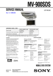
» Contents Page
Service Manual
HP MDTV Rear Projection TVs
Fall 2005
L1735A, L1736A, L1737A, L1798A
Preface
This manual is prepared for the maintenance service for HP's 50”, 58”, and 65” Rear Projection Multi-Purpose Display Unit. Maintenance procedures described in this manual are intended to isolate faulty parts and replace them in the field. It also aims to serve as a guide in
procuring replacement parts for this product.
This manual is copyrighted and all rights are reserved. This product may not, in whole or in
part, be copied, photocopied, translated or reduced to any electronic or machine readable
form without prior written consent except for copies retained by the purchaser for backup
purpose.
This manual includes basic specifications, major system assembly, components’ description,
and the “Troubleshooting” making explanations on how to detect errors. It also includes a flow
chart for checking or correcting faults.
No warranty or representation, either expressed or implied, is made with respect to this
documentation, its quality, performance, merchantability or fitness for particular purpose.
No event that the vendor will be liable for direct, indirect, special, incidental or consequential
damages arising out of the user or inability to use this product or documentation.
NOTICE :
The information found in this manual is subject to change without prior notice. Any subsequent
changes made in the data herein will be incorporated in further edition.
HP MDTV
2
Table of Contents
On-line links to chapter beginning
Introduction HP MDTV Product Information
Why HP High Definition? ...........................................................................................................4
Wobulation .................................................................................................................................5
Industrial Design ........................................................................................................................6
MDTV Features..........................................................................................................................7
Model Information ......................................................................................................................8
Accessories................................................................................................................................9
Model Specifications ................................................................................................................10
Chapter 1
Technical Specifications ...................................................................................................11
Chapter 2
Disassembly Procedure
Tools Needed...........................................................................................................................20
Disassemble Lamp Module......................................................................................................21
Disassemble Rear cover & Power Supply Module ..................................................................23
Disassemble System Fan, Main Board Module & Amplifier Board..........................................26
Disassemble Engine module ...................................................................................................30
Disassemble Speakers & Keypad Board .................................................................................34
Chapter 3
Troubleshooting
Main Procedure........................................................................................................................35
Power Troubleshooting ............................................................................................................36
Image Performance Troubleshooting.......................................................................................38
Sound Troubleshooting............................................................................................................39
Remote Control Troubleshooting .............................................................................................40
Chapter 4
Alignment & Function Test Procedure
Hot Key ....................................................................................................................................41
Function Test ...........................................................................................................................41
ADC Calibration .......................................................................................................................45
Optical Alignment .....................................................................................................................46
Chapter 5
Upgrade Procedure
Equipment Needed ..................................................................................................................47
USB Upgrade Function Overview ............................................................................................47
USB Flash Disk Usage ............................................................................................................47
Upgrade LED Indication...........................................................................................................48
USB Upgrade Procedure .........................................................................................................49
Error Handling ..........................................................................................................................49
Chapter 6
EDID Upgrade Procedure
Tools Needed...........................................................................................................................50
Setup Procedure ......................................................................................................................50
Notice .......................................................................................................................................56
Appendix A Exploded Overviews and Parts Lists .......................................................................................58
Appendix B System Serial Number Definition .............................................................................................74
Appendix C Glossary ................................................................................................................................75
3
Why HP High Definition?
The digital entertainment revolution is in full swing.
Digital cameras, digital camcorders, and CD
and DVD players already rule their respective
markets, empowering home consumers to easily
and affordably create, manage, and enjoy high
quality viewing and listening experiences. And
the next big wave—already roaring towards shore
and about to break—is high definition television.
HP is positioned to ride that wave with a complete
lineup of high definition TVs that will swamp the
competition with everything our customers want:
competitive pricing, unequaled ease of use, and
mind-boggling image quality.
HP HDTV is the latest and most exciting creation
of HP Visual Fidelity technologies. It’s grounded in
HP’s decades-long history of engineering excellence
and color science leadership. And it’s infused with
our unparalleled cutting-edge technological drive
and our determination to provide our customers with
digital entertainment products that are simple to use
yet produce consistently stunning visual experiences.
Pioneering innovation has always been a priority
at HP (take for example, the front connect panel on
the MDTVs). Nowhere is that innovative edge more
apparent, or more crucial to the company’s industryleading position, than in the application of color
science to electronic technology. For more than
two decades, HP has led the way in color science.
That experience and the depth of knowledge it
represents are key to the company’s new entry into
the home digital entertainment market. HP engineers
have taken what they know about ink, and applied
it to light—the science underlying ink droplets is
surprisingly similar to that of light droplets.
The result immerses the viewer in a dazzling home
theater experience: true-to-life color combined
with startlingly crisp image quality and ear-tingling
sound, all in an attractive, easy-to-use package at
a competitive price. That’s the HP HDTV experience.
4
The Wobulator
Images without Wobulation (top) are dramatically improved by
two-position Wobulation, which doubles the resolution.
The technology story:
HP Visual Fidelity and
Wobulation
Microdisplay TV and Wobulation
Wobulation is a funny name for a great technology.
And it’s another great example of HP ingenuity at
work—leveraging our industry-leading inkjet technology into new and dazzling consumer products.
HDTV and HP Visual Fidelity
Thanks to HP’s Visual Fidelity technologies—the
power behind the picture—our HDTVs deliver
unrivaled image quality and color brilliance.
Here’s how: both printers and digital projectors
create a color picture from a matrix of primary
color points. Historically, print resolution was
increased by placing more and overlapping ink
droplets within the same size grid; initially,
300 x 300 dot-per-inch (dpi) resolution became
600 x 300 dpi. That yielded significantly better
image quality from the same size dots of ink.
In LCD and plasma models, HP Visual Fidelity
technologies provide an advanced video pipeline
that combines photorealistic sharpness enhancement, scene-by-scene contrast adaptation keyed
to the room’s ambient lighting, and a 3D colorenrichment system.
HP Visual Fidelity includes technologies such as
Wobulation, which doubles the pixel resolution to
provide brilliant, crisp, true-to-life images. (See
illustration, above.) The lamp is brighter, offering
more accurate, vivid colors and an ultra-wide
viewing angle. And DLP™ technology fine-tunes
each individual pixel for a cleaner, sharper image.
HP engineers simulated applying the same principle
to “droplets” of light, with exciting results. Same
size spots, yet dramatically improved image quality.
In fact, the resulting light-imaging technology—
Wobulation—doubles the addressed resolution of
non-Wobulated, digitally projected images, without
diminishing their renowned crispness. This technology
virtually eliminates the screen-door effect commonly
seen in other displays. And it’s accomplished without expensive modifications, like changing the light
All HP HDTV models feature high contrast ratios for
modulator or increasing pixels.
brighter lights and deeper darks. That means truer
blacks—enhancing image sharpness and power,
Better resolution, eye-popping picture quality,
whether the scene is action-packed or brightly lit
virtually no increase in cost. So, HP customers who
or darkly shadowed. It means subtler color detail.
choose our MDTVs get the best possible HDTV
And it means increased tolerance of ambient light. viewing experience at a price they can afford.
The bottom line? A viewing experience like no
other, rich with stunning detail and true-to-life colors.
5
Industrial design
Form, function, and style
The HP HDTVs are as beautiful as the images they produce. Stylishly thin, the HP Plasma and LCD TVs
complement any décor and take up less space than a traditional TV. And they’re remarkably easy to
use; our intuitive onscreen menus and ergonomic remote controls turn typical setup and operation
nightmares into sweet dreams.
The satin-finished metal framing and cabinetry of
the HP MDTVs is mirrored in the optional matching
stands, as is their unique integrated cable management system. HP MDTVs feature a revolutionary
lighted, front-mounted quick-connect panel that
allows A/V cables to be easily connected from the
front, then hidden from view. Thumbnail source
selection (up to ten sources) and preset customizable
video and audio modes are key to their unparalleled
ease of use. And their built-in 85-watt audio system
with integrated subwoofer and SRS TruSurround
XT™ delivers thrilling sound.
6
HP MDTV:
a new approach
HP MDTV features
DLP™
While all
TVs share common characteristics,
you can really see the differences in HP MDTVs in
the areas of picture, sound, connectivity, styling,
and ease of use.
The 720p TVs—50-inch and 58-inch models—are
entry-level, offering great picture quality and ease
of setup. The higher end 1080p TVs, the 58-inch
and 65-inch models, feature advanced picture
technology, and are two of the few 1080p TVs on
the market capable of receiving and displaying
native 1080p compressed and uncompressed HD
content through HDMI at three frame rates. This
gives the consumer the opportunity to select from
price and feature options to fit individual budgets
and taste. HP is future-proofing the consumer’s
expensive investment.
HP Visual Fidelity
• HP Wobulation uses resolution doubling to produce
clean, crisp images and virtually eliminates
screen-door effect.
• The DynamicBlack™ aperture enhances resolution
for a smoother picture, vivid colors, fine detail,
and darker blacks.
• The white point in these TVs is truly white, making
it possible to see natural subjects in natural colors.
• The 1080p models (md5880n and md6580n)
are capable of receiving and displaying native
1080p compressed and uncompressed HD content
(through HDMI at three frame rates).
• HP-enhanced DLP technology and a brighter bulb
sharpen contrast ratios while delivering more vivid
color and less fall-off.
Image quality
• Picture uniformity across the screen makes for
an ultra-wide viewing angle, both horizontal
and vertically.
• The screen’s flatness and focal length improve
image sharpness and virtually eliminate glare
and reflection.
• The brighter 150-watt DC UHP lamp produces
more vivid color, more contrast, and less fall-off,
with no flicker. The picture is rich with detail,
even in daylight.
• The color wheel and lamp work together to deliver
more natural colors, especially noticeable in
realistic skin tones and truer greens.
• Color temperature is lower and warmer overall,
for a more true-to-life picture.
Connectivity
HP Visual Fidelity: the science of great image quality • Lighted, front connection panel provides inputs
for common sources such as a TV antenna and
HP’s rich assets and printing technology intelligence
cable service, a DVD player, an audio/video
have been employed to transform the art and science
receiver, a VCR, a personal digital video recorder,
of display. When we say “HP Visual Fidelity,” we’re
an HD camcorder, a video gaming device, a
talking about HP technologies that work together
personal computer, and a satellite receiver.
to provide outstanding image quality and color:
• The 1080p TVs are Digital Cable Ready with an
• HP Wobulation/resolution enhancement
integrated CableCARD slot. The 720p TVs allow
• Color science
for an optional CableCARD tuner module,
• Image processing and rendering
eliminating the need for a separate cable box.
• Illumination
• Viewing experience
7
HP MDTV models
Lighted, front
connection panel
HP md5880n
HP md6580n
HP Pavilion Microdisplay 1080p TV key features:
• High-definition 1080p resolution with contrast ratios up to 12,000:1 and built-in HD tuner
• HP Visual Fidelity™ technology for fine detail with warm, rich colors and natural skin tones
• Crisp, detailed blacks via the DynamicBlack™ aperture and 7-segment color wheel; ultra-wide
viewing angle, brighter 150w lamp
• Front-mounted Quick Connect panel for easy setup and use
• Industry first—thumbnail previews for easy source selection
• 2.1 audio, 85w (peak), integrated subwoofer, and SRS TruSurroundXT™
• CableCARD™ ready; optional matching stand with enhanced cable management
HP md5020n
HP md5820n
HP Pavilion Microdisplay 720p TV key features:
• High-definition 720p resolution; excellent contrast ratios and built-in HD tuner
• HP Visual Fidelity™ technology for fine detail with warm, rich colors and natural skin tones
• Front-mounted Quick Connect panel for easy setup and use
• Industry first—thumbnail previews for easy source selection
• Ultra-wide viewing angle, brighter 150w lamp
• 2.1 audio, 85w (peak), integrated subwoofer, and SRS TruSurroundXT™
• Optional CableCARD™ tuner and matching stand with enhanced cable management
Accessories:
remote control and stand
HP MDTV Remote Control
All HP MDTV models include a unique, ergonomically designed remote control
that’s been HP-engineered for years of smooth and reliable performance. It
nestles comfortably into your hand, responds decisively to your touch, and
intuitively translates your every command, instantly and flawlessly. The remote
allows you to access the TV like a pro videophile or like a regular consumer.
You’ll probably find yourself wishing you could use it to control the rest of
your life, too.
David Katzmaier, in his glowing test report in Sound & Vision Magazine
(October 2005), said “The TV’s Settings menu has more options than a panAsian takeout joint.”
HP MDTV Stand
The HP TV Stand is the perfect accessory for your new HP MDTV. It’s a
continuation of the sleek, clean design of your TV, and holds it at the ideal
viewing height. It’s designed to discreetly yet effectively manage your
cables—no more unsightly, tangled snake pit! And, the stand comfortably
houses at least four standard home entertainment peripherals (DVD player,
receiver, etc.).
9
720p resolution with Wobulation (1280 x 720)
•
•
•
•
Built-in 2.1 audio system (85-watt peak) with
integrated subwoofer
SRS TruSurround XT™ including Dialog Clarity
Enhancement and TruBass
•
•
•
•
•
•
Four customizable video and audio preset modes
Intuitive, ergonomic, universal remote control
Matching stand with enhanced cable management
•
•
•
•
•
•
•
integrated
•
•
•
•
•
•
•
•
•
•
•
integrated
•
•
•
•
•
•
•
•
•
•
•
65-inch screen (165cm)
133lb (60kg)
66.5x41.0x20.2in
(168.9x104.1x51.4cm)
HP Pavilion
md6580n
•
•
•
58-inch screen (147cm)
117lb (53kg)
60.0x38.0x19.2in
(152.4x96.5x48.9cm)
HP Pavilion
md5880n
*For more detailed information on the features and benefits described here, please refer to the DVD included with this kit.
**Native or compressed format
Optional extras
Tuners for both digital and analog sources;
built-in ATSC tuner
•
•
•
•
•
•
optional
On-screen thumbnail display for source selection
User Interface
Video input** 1080p at 24, 30, and 60 fps (through HDMI)
Video input** 480i/p, 720i/p, 1080i
Video handling
optional
•
•
Connection for up to 10 sources, including HDMI,
component video, S-video/composite-video, VGA,
coaxial cable, and more
CableCARD™ tuner module slot
•
•
Illuminated front-mounted connectivity panel with
integrated cable management slot
Connectivity
Sound
•
•
•
•
•
•
Brighter 150w DC UHP lamp
SmoothPicture™, DynamicBlack™ aperture
Seven-segment color wheel with DVE (Digital Video
Enhancement)
Six-segment color wheel
DLP™ featuring HP Visual Fidelity technology
with steeper contrast ratio (up to 12,000:1)
DLP™ featuring HP Visual Fidelity technology
with steep contrast ratio (up to 2,200:1)
1080p high-definition resolution with Wobulation
(1920 x 1080)
117lb (53kg)
58-inch screen (147cm)
•
50-inch screen (127cm)
Unique dual-component screen, measured
diagonally; 16:9 widescreen for all models
60.0x38.0x19.2in
(152.4x96.5x48.9cm)
HP Pavilion
md5820n
•
102lb (46kg)
Weight
Picture
53.0x34.0x17.2in
(134.6x86.4x43.8cm)
HP Pavilion
md5020n
Size
Physical characteristics
HP MDTV
specifications*
Comfortable, responsive movement through onscreen menus and controls
Quickly choose from modes tailored to the specific combination of room
and source
Switch between digital and analog signals with the push of a button
Easy push-button snapshot view and selection of up to ten sources
Make the most of 1080i and 1080p content
All the 1080i content you would need
Eliminates the need for a cable box
Get the most from your viewing experience from a variety of sources
Easier set-up and device management; cables tucked away, out of sight
Thumping home theater sound
Stereo sound independent of audio components
Ultra-wide viewing angles; more contrast, less fall-off; better daytime viewing
Blacker blacks, richer color tone, increased contrast, and greater detail
in darker scenes
Superior, lifelike, saturated colors and dramatic reduction of “dither noise”
in darker tones
Superior, lifelike, saturated colors
Incredible sharpness, brightness, and contrast, with improved picture
reliability, stunning rich blacks, and greater detail in darker scenes
Increased sharpness, brightness, and contrast, with improved picture
reliability and greater detail in darker scenes
Ability to receive and reproduce highest quality native and compressed signals
from any source; clean, crisp images and virtually no screen-door effect
Ability to receive and reproduce highest quality signals from any source
Chapter 1
Specifications
Technical Specification
The Zappa Family of Digital TVs consists of a portfolio of four TVs. The following table highlights the individual products.
Product Name
Summary of Differentiating Features
MD5020
Screen Size: 50"
DMD Resolution: HD4 1280 x 720
Turner: NTSC, ATSC, Clear QAM
MD5820
Screen Size: 58"
DMD Resolution: HD4 1280 x 720
Tuner: NTSC, ATSC, Clear QAM
MD5880
Screen Size: 58"
DMD Resolution: xHD4 1920 x 1080
Tuner: NTSC, ATSC, QAM w/ Cable Card
MD6580
Screen Size: 65"
DMD Resolution: xHD4 1920 x 1080
Tuner: NTSC, ATSC, QAM w/ Cable Card
1. Lamp
MD5020/ MD5820/ MD5880/ MD6580
Manufacture
Phoenix
Electrode Gap
1.1mm (Open type) with ellipse reflector E23
Wattage
150Wdc SHP Lamp
Rated Life
6000 hrs. (Typ.)/150W (based on lamp spec.)
Lamp Replacement Barrier
With warning label "DANGER: RISK OF EXPLOSION.
REPLACE LAMP IN ACCORDANCE WITH ALL
MANUFACTURER'S INSTRUCTIONS
11
2. Panel
MD5020/ MD5820
Manufacture
Texas Instruments
Type
HD4 DMD Chip
Size
0.55 inch
Total Pixels
640(H) x 720(V) Diamond pixels
Active Pixels
1280(H) x 720(V) Pixels
MD5880/ MD6580
Manufacture
Texas Instruments
Type
xHD4 DMD Chip
Size
0.843 inch
Total Pixels
960(H) x 1080(V) Diamond Pixels
Active Pixels
1920(H) x 1080(V) Pixels
3. Color Wheel
MD5020/ MD5820
Manufacture
KYO
Type
6 segments including with SLR on (spoke light recapture)
Motor
55mm diameter
S pi n S peed
10,800 rpm/NTSC
MD5880/ MD6580
Manufacture
KYO
Type
7 segments including with SLR on (spoke light recapture)
Motor
65mm diameter
S pi n S peed
10,800 rpm/NTSC
12
4. Screen Image
MD5020
Image Siz e
50 inches (1270.0mm)
Aspect Ratio
16:9
Image Horizontal Size
1106.9mm
Image Vertical Size
622.63mm
Projection Distance
608.746mm +/- 4.56mm (based on YOI Engine Spec.)
Distortion
(Horizontal), (Vertical)
2.0% (+/- 1.0%)
Over Scan
Diagonal 4% +/- 1%
MD5820
Image Siz e
58 inches (1473.2mm)
Aspect Ratio
16:9
Image Horizontal Size
1284.01mm
Image Vertical Size
722.25mm
Projection Distance
714.276mm +/- 5.35mm (based on YOI Engine Spec.)
Distortion
(Horizontal), (Vertical)
2.0% (+/- 1.0%)
Over Scan
Diagonal 4% +/- 1%
Distortion
(Horizontal), (Vertical)
2.0% (+/- 1.0%)
Over Scan
Diagonal 4% +/- 1%
MD5880
Image Siz e
58 inches (1473.2mm)
Aspect Ratio
16:9
Image Horizontal Size
1284.01mm
Image Vertical Size
722.25mm
Projection Distance
698.1mm +/- 5.35mm (based on YOI Engine Spec.)
Distortion
(Horizontal), (Vertical)
2.0% (+/- 1.0%)
Over Scan
Diagonal 4% +/- 1%
MD6580
Image Siz e
65 inches (1651.0mm)
Aspect Ratio
16:9
Image Horizontal Size
1438.97mm
Image Vertical Size
809.42mm
Projection Distance
788.6mm +/- 5.9mm (based on YOI Engine Spec.)
Distortion
(Horizontal), (Vertical)
2.0% (+/- 1.0%)
Over Scan
Diagonal 4% +/- 1%
13
5. Input Signal Characteristics
Analog RGB Input
Connector(s) Type
D-sub 15 pin
Resolution Compatibility
See Table 1.1
Digital RGB Input
Connector(s) Type
DVI Single Link
Resolution Compatibility
"Same as Analog"
Video Input
C ompati bi li ty
NTSC , PAL, S-Vi deo (Y/C ), C omposi te Vi deo
14
TV Input
Table 1.1
Connector
Signal
HxV/FrameRate
RF
Analog
Terrestrial
SMPTE 170M,
720 x 480i/29.97 (4:3)
720 x 480i/29.97 (16:9) EIA-608,
EIA-J CPR-1204,
IEC61880,
BT. 1119,
EIA/IS-702
EIA-744
54MHz-806MHz
carrier range,
(M)NTSC
modulation: 525-lines,
2:1 interlace, 59.94Hz fields/sec,
Fsc=3.58MHz,
BTSC audio, CC, XDS, CGMS-A,
WSS
RF
Analog
Cable
720 x 480i/29.97 (4:3)
720 x 480i/ 29.97
(16:9)
ANSI/SCTE 40 2004,
SMPTE 170M
EIA-608,
EIA-J CPR-1204,
IEC61880,
BT.1119,
EIA/IS-702,
EIA-744
54MHz-1002MHz
carrier range
(STD, IRC, HRC)
modulation: 525-lines,
2:1 interlace,
59.94Hz field/sec,
Fsc=3.58MHz,
BTSC audio,
CC, XDS, CGMS-A, WSS
RF
Digital
Terrestrial
ATSC A/52,
ATSC A/53,
ATSC A/54,
ATSC A/57,
ATSC A/64,
ATSC A/65,
EIA-708,
EIA-766
54MHz-806MHz
carrier range
8-VSB modulation,
Dolby DIgital audio,
Table A3 video
formats
640 x 480i/ 29.97
640 x 480i/30
640 x 480p/23.976
640 x 480p/24
640 x 480p/29.97
640 x 480p/30
640 x 480p/59.94
640 x 480p/60
704 x 480i/29.97 (4:3)
704 x 480i/30 (4:3)
704 x 480p/23.976
(4:3)
704 x 480/24 (4:3)
704 x 480p/29.97 (4:3)
704 x 480p/30 (4:3)
704 x 480p/59.94 (4:3)
704 x 480p/60 (4:3)
704 x 480i/29.97 (16:9)
704 x 480i/30 (16:9)
704 x 480p/23.976
(16:9)
704 x 480p/24 (16:9)
704 x 480p/29.97
(16:9)
704 x 480p/30 (16:9)
704 x 480p/59.94
(16:9)
704 x 480p/60 (16:9)
1280 x 720p/23.976
1280 x 720p/24
1280 x 720p/29.97
1280 x 720p/30
1280 x 720p/59.94
1280 x 720p/60
1920 x 1080i/29.97
1920 x 1080i/30
1920 x 1080p/23.976
1920 x 1080p/24
1920 x 1080p/29.97
1920 x 1080p/30
Standards
15
Details
Connector
Signal
RF
Digital
Cable
HxV/FrameRate
Standards
Details
ANSI/SCTE 40 2004
54MHz-1002MHz
carrier range,
64QAM or 256QAM
in-band modulation,
QPSK out-of-band modulation,
Dolby DIgital audio,
Table A3 video formats, CableCard:
Digital Cable Ready
640 x 480i/29.97
640 x 480i/30
640 x 480p/23.976
640 x 480p/24
640 x 480p/29.97
640 x 480p/30
640 x 480p/59.94
640 x 480p/60
704 x 480i/29.97 (4:3)
704 x 480i/30(4:3)
704 x 480p/23.976 (4:3)
704 x 480p/24 (4:3)
704 x 480p/29.97 (4:3)
704 x 480p/30 (4:3)
704 x 480p/59.94 (4:3)
704 x 480p/60 (4:3)
704 x 480i/29.97 (16:9)
704 x 480i/30 (16:9)
704 x 480p/23.976 (16:9)
704 x 480p/24 (16:9)
704 x 480p/29.97 (16:9)
704 x 480p/30 (16:9)
704 x 480p/59.94 (16:9)
704 x 480p/60 (16:9)
1280 x 720p/23.976
1280 x 720p/24
1280 x 720p/29.97
1280 x 720p/30
1280 x 720p/59.94
1280 x 720p/60
1920 x 1080i/29.97
1920 x 1080i/30
1920 x 1080p/23.976
1920 x 1080p/24
1920 x 1080p/29.97
1920 x 1080p/30
C BVS
(M)NTSC
640
640
720
720
864
864
940
960
x 480i/29.97 (4:3)
x 480i/30 (4:3)
x 480i/29.97 (4:3)
x 480i/30 (4:3)
x 480i/29.97 (16:9)
x 480i/30 (16:9)
x 480i/29.97 (16:9)
x 480i/30 (16:9)
BT.601,
SMPTE 170M
EIA-608,
EIA-J CPR-1204,
IEC61880,
BT.1119,
EIA/IS-702,
EIA-744,
BT.656
16
Connector
Signal
S-Video
(M)NTSC
HxV/FrameRate
Standards
BT.601,SMPTE 170M,
EIA-608, EIA-J CPR-1204, IEC61880,
BT.1119, EIA/IS-702, EIA-744
40 x 480i/29.97 (4:3)
640 x 480i/30 (4:3)
720 x 480i/29.97 (4:3)
720 x 480i/30 (4:3)
864 x 480i/29.97 (16:9)
864 x 480i/30 (16:9)
940 x 480i/29.97 (16:9)
960 x 480i/30 (16:9)
Component
480i
YPbPr
640
640
720
720
864
864
940
960
Component
BT.601
SMPTE 170M
EIA-770.1, EIA-770.2,SMPTE293M
480p
YPbPr
640
640
720
720
864
864
940
960
Component
x 480i/29.97 (4:3)
x 480i/30 (4:3)
x 480i/29.97 (4:3)
x 480i/30 (4:3)
x 480i/29.97 (16:9)
x 480i/30 (16:9)
x 480i/29.97 (16:9)
x 480i/30 (16:9)
x 480i/59.94 (4:3)
x 480i/60 (4:3)
x 480i/59.94 (4:3)
x 480i/60 (4:3)
x 480i/59.94 (16:9)
x 480i/60 (16:9)
x 480i/59.94 (16:9)
x 480i/60 (16:9)
BT.709, SMPTE 296M, EIA-770.3
720
YPbPr
1280
1280
1280
1280
Component
x 720p/23.976
x 720p/24
x 720p/59.94
x 720p/60
1080i
YPbPr
1920 x 1080i/29.97
1920 x 1080i/30
Component
BT.601
SMPTE 170M
EIA-770.1,EIA-770.2,EIA-608
EIA-J CPR-1204
IEC61880,EIA/IS-702
EIA-744
SMPTE125M
1080p
YPbPr
1920
1920
1920
1920
x 1080p/23.976
x 1080p/24
x 1080p/29.97
x 1080p/30
BT.709,
SMPTE 274M
EIA-770.3
BT.709,
SMPTE 274M
EIA-770.3
17
Details
Connector
Signal
HDMI/DVI
HxV/FrameRate
Standards
Details
Note: (16:9)formats
should have priority over (4:3)
formats. This means the (16:9)
formats should appear first in the
E-EDID structure.
High-Difinition
Multimedia Interface
Specification,
CEA-861B,
(and compatible with Digital
Visual Interface)
CEA EDID Timing
Extension Version 3
should be used. This
provides support for
more than "Basic
audio" and support for
both (16:9) and (4:3)
aspect ratios.
720 (1440) x 480i/29.97 (4:3)
720 (1440) x 480i/ 30 (4:3)
2880 x 480i/29.97 (4:3)
2880 x 480i/30 (4:3)
640 x 480p/59.94 (4:3)
640 x 480p/60 (4:3)
720 x 480p/59.94 (4:3)
720 x 480p/60 (4:3)
1440 x 480p/59.94 (4:3)
1440 x 480p/60 (4:3)
720 (1440) x 480i/29.97 (16:9)
720 (1440) x 480i/30 (16:9)
2880 x 480i/29.97 (16:9)
2880 x 480i/30 (16:9)
640 x 480p/59.94 (16:9)
640 x 480p/60 (16:9)
720 x 480p/59.94 (16:9)
720 x 480p/60 (16:9)
1440 x 480p/59.94 (16:9)
1440 x 480p/60 (16:9)
1280 x 720p/59.94
1280 x 720p/60
1920 x 1080i/29.97
1920 x 1080i/30
1920 x 1080p/23.976
1920 x 1080p/24
1920 x 1080p/29.97
1920 x 1080p/30
VGA
Primary
Primary
Primary
Primary
Primary
Primary
Primary
Primary
Primary
Primary
VESA Display Monitor Timing
Standard (Unless otherwise
specified)
VGA
640
640
640
640
x 480p/60
x 480p/72
x 480p/75
x 480p/85
480p
720 x 480p/60
(26.719MHz, Horiz Freq
29.820kHz, Neg Hsync, Pos
Vsync)
VESA Generalized Timing
Formula Standard
480p
720 x 480p/60
CEA-861B
480p
720 x 480p/60
SVGA
800
800
800
800
800
XGA
1024
1024
1024
1024
x 600p/56
x 600p/60
x 600p/72
x 600p/75
x 600p/85
x 768p/60
x 768p/70
x 768p/75
x 768p/85
18
Connector
Signal
HxV/FrameRate
Standards
Details
720p
1280 x 720p/60 (74.841MHz, Horiz Feq
44.769kHz, Neg Hsync, Pos Vsync)
VESA Generalized Timing
Formula Standard
720p
1280 x 720p/60
CEA-861B
720p
1280 x 720p/60
TBD
1080i
1920 x 1080i/29.97
1080i
1920 x 1080i/30
1080p
1920 x 1080p/29.97
1080p
1920 x 1080p/30
1080p
1920 x 1080p/23.976
1080p
1920 x 1080p/24
WXGA
1280 x 768p/60
(68.250MHz)
1280 x 768p/60
(79.500MHz)
1280 x 768p/75
1280 x 768p/85
1360 x 768p/60
SXGA
1280 x 1024p/60
1280 x 1024p/75
6. Audio System
Pow er Amplifier (Satellite)
Power
15W RMS/THD= 10%, R=8 ohm at 1 kHz
Frequency Response
70hz-15khz
Speakers (Satellite)
Power
15W RMS
Frequency Response
85-15khz
Pow er Amplifier (Subw oofer)
Power
25W RMS/THD= 10%, R=4 ohm at 100Hz
Frequency Response
30hz-3khz
Speakers (Satellite)
Power
25W RMS
Frequency Response
25-3khz
7. Physical
5020
5820
5880
6580
Physical Dimensions
(H*W*D)mm
868 x 1350 x 432
967 x 1530 x 482
967 x 1530 x 482
1055 x 1682 x 530
Weight Kgs
47
52
54
62.5
19
Chapter 2
Disassembly Procedure
Tools Needed
20
Disassemble Lamp Module
1.
Remove Easy Door Module.
2.
Unscrew 2 screws and then remove Lamp Cover (as 2 red circles show).
Lamp Cover
21
3.
Loosen 3 screws and then remove the Lamp Module.
Lamp Module
22
Disassemble Rear Cover and Power Supply Module
1.
Unscrew 10 screws and then remove the Rear Cover.
Rear Cover
23
2.
Unscrew 4 screws (step 1), unscrew 1 screw (step 2), unsrew 8 screws (step 3),
unplug 9 connectors (step 4) to remove Power Supply Module.
Step 1
Step 3
Step 1
Step 2
Step 4
24
3.
Unscrew 4 tenons shown in the red circle to remove Ballast from LVPS.
Ballast
LVPS
25
Disassemble System Fan, Main Board Module and
Amplifier Board
1.
Unscrew 2 screws to remove System Fan.
XHD4 Model:
HD4 Model:
26
2. Unscrew 3 screws (step 1), unscrew 5 screws (step2 & step 3) (shown in the yellow
square), unplug 17 connectors (XHD4)/ 16 connectors (HD4) (shown in red circle)
to remove Main Board Module.
XHD4 Model:
Step 1
Step 2 & Step 3
HD4 Model:
Step 1
Step 2 & Step 3
27
3. Lossen 4 tenons to remove Amplifier Board from Main Board Module.
4. Unscrew 14 screws (shown in red circle), 2 hex screws (shown in yellow square) to
remove Main Board Cover from Main Board Module.
28
5. Unscrew 2 screws to remove Cable Card Accessory. (for XHD4 model only)
6. Unscrew 2 Nuts (shown in yellow square) and 5 screws (shown in red circle) to re
move Tuner Board.
7. Lossen 2 tenons to remove Audio Board.
8. Unscrew 4 hex and 2 screws (step 1), 5 screws (as yellow circle) and 5 screws (as
red circle) (step 2) to remove Main Board.
Step 1
Step 2
29
Disassemble Engine Module
1.
Disconnect 3 connectors and unscrew 2 screws from the rear side of TV.
2.
Unscrew 4 screws to remove Front Cover. Note: Please use star type screwdriver.
3.
Unscrew 4 screws from Engine Module.
30
4.
Unscrew 2 screws to remove the cover the Speaker.
5.
Unscrew 2 screws to remove the holding parts.
31
6.
Remove 4 covers from the top of the TV first and remove 4 screws after, then the
screen can be removed.
Inside
Outside
Note: 1. To prevent the damage, use a sponge to support the screen.
2. Inside of the screen is brighter than outside.
7.
To gently remove the Engine Module, cover the lens with a Lens cover to preventing
damage.
Lens Cover
32
8.
Unscrew 1 screw to remove Thermal Sensor.
9.
Unscrew 3 screws to remove Engine Fan.
33
Disassemble Speaker Module and Keypad Board.
1.
Unscrew 8 screws and lossen 4 connectors to remove Speaker Module.
2. To remove Keypad Board, unscrew 4 screws and 1 connector.
34
Chapter 3
Troubleshooting
Main Procedure
35
Power Troubleshooting
36
37
Image Performance Troubleshooting
38
Sound Troubleshooting
39
Remote Control Troubleshooting
40
Chapter 4
Alignment & Function Test Procedure
Action Reference
Change parts/update Optical Alignment
ADC Calibration
Function Test
Channel Scan
Main Board
V(*)
V(**)
V
Firmware
V(*)
V(**)
EDID
V(*)
V(**)
V(**)
V(***)
Engine
V(*)
LVPS or Ballast
Board
V
Amp. Board
V
Tuner Board
V
Keypad Board
V
* : 1st step
** : 2nd step
*** : 3rd stepstep
Hot Key
- Factory Menu: Press “Source”, “-”, “CC”, “SAP”
to enter Factory Menu.
Function Test
A. Video/Audio
Test Instrument Facility:
1. Remote controller * 1
2. DVD player * 1 (must have the HDMI and DVI port)
3. Cable * 1 (component, composite, s-video, HDMI, DVI to HDMI, SPDIF)
4. VGA cable * 1 (D-sub 15 pin, audio)
5. Pattern generator * 1 (it can generate the 16 gray scale picture)
6. TV signal generator * 1 (optional, if antenna signal is ready)
41
42
43
Keypad
test
(1)Press SOURCE button on the remote
control and choose source to
Component 2 .
(2)Connect to DVD component signal
Check if the keypad
function
work well.
Remote
Control test
(1)Press SOURCE button on the remote
control and choose source to video 2.
(2)Connect to DVD composite signal
Check if the Remote
Control
function work well.
44
ADC Calibration
ADC - YPbPr Calibration
1.
2.
3.
Input “SMPTE”Test patter (Figure 1) from generator to TV component port. (component 1
or 2 is ok)
TV set to Factory Menu. Use cursor on the remote to move to “ADC Calibration” setting.
Like Figure 2.
Press “OK” on the remote.
ADC - VGA Calibration
1.
2.
3.
Input 16 gray scale pattern (Figure 1) from generator to TV VGA port.
TV set to Factory Menu. Use cursor on the remote to move to “ADC Calibration” setting.
Like Figure 2.
Press “OK” on the remote controller.
45
4-4 Optical Alignment
Test
Item
Working Items
1
Plug the power cord into socket behind Voltage 110V power cord should be
connected firmly
TV
2
Switch on power and press keypad
power button to ignite Lamp
3
Enter the factory mode
4
Press ok to enter Optical Alignment
color bar for image
slope/shape/trapezoid to go to the
permit area
Default value: md5020/5820:
left, right: 25 up, bottom: 16
md5880/ 6580:
left, right: 37 up, bottom: 20
5
Move and rotate engine module, adjust
center line to frame
6
If the image is too high, adjust front I
type screw clockwise rotation, then the
screen will be moved to the lower side.
If the picture is too low, adjust I type
screw to counter clockwise the unit in
order to move the picture higher.
7
Use ratch wrench locking front two
fixed studs.
8
Revolve TV, use ratch wrench locking
back twofixed studs. Attention: When
locking, can't damage the wire.
9
Revolve TV again, use gule machine to drop glue range area: screw circle 1/3
drop location to two I type screw
linear.
Check item/Spec/Figure
Check if Lamp is on
46
Chapter 5
Firmware Upgrade Procedure
Equipment Needed
Software :
- Zappa Projection Firmware
Hardware :
- Zappa Projection TV
- USB Flash Disk
USB Upgrade Function Overview
Zappa builds in USB OTG chip for F/W upgrade purpose; user just put F/W hex code into
USB Flash Disk, and then plug it to USB receptacle of TV, system will upgrade the F/W to
appropriate unit. There are 7 units can be upgrade, MTV512, VGA EDID, HDMI 1 EDID,
HDMI 2 EDID, Pixel works Flash, DTV module Flash and CSC1220.
USB Flash Disk Usage
Zappa USB OTG only recongnizes USB flash disk device, other devices will be ignored.
a. File system: USB driver support FAT 12, FAT 16 and FAT 32 file systems. Also support
OTG HOST mode only.
b. File location: User can put F/W hex code in any directory or root directory.
c. Sub File Name: Current driver only can recognize *.hex sub file name. So you may need to
rename the sub file name to be “HEX”, such as DTV module, that F/W file name is
“vxWorks_user.bin”, you need to rename it to be “vxWorks_user.hex”.
d. File Name: Driver recognizes prefix file name then decide which unit should be upgraded,
you can put any characters after prefix, such as date or version. For example, Mtv512_v02.
hex, “Mtv512” is prefix and driver will recognize it and upgrade it to MTV512. The prefix file
name of each unit list as below.
47
Upgrade Unit
MTV512
CSC1220
VGA EDID
Prefix File Name
MTV512
CSC1220
VGAEDID5020/
VGAEDID5820/
VGAEDID5880/
VGAEDID6580/
HDMI EDID
HDMIEDID5020/
HDMIEDID5820/
HDMIEDID5880/
HDMIEDID6580/
Pixel Works
APPCODE720P/
APPCODE1080P
FLASHER.HEX
DTV Boot Code BOOTROM
DTV Module
VXWORKS_USER
Upgrade Sequence
1
2
3
4
5
6
7
You can put all of above files into disk or individual file that depend on what unit you want to
upgrade. And driver will follow the upgrade sequence to upgrade each unit.
About VGA EDID and HDMI EDID, you can put all of model’s EDID code in one USB Flash
Drive, USB will according to product ID in EDID EEP ROM to choice correct EDID code.
Note: if the EDID EEP ROM is emtpy or the product ID is wrong, USB will pick one of
EDID code on the flash drive to upgrade. So, if you already know the EDID is empty,
just put one EDID code that you want to upgrade in USB Flash Drive.
Upgrade LED Indication
Due to LED are controlled by MTV512, so when MTV512 is upgrading, the LED will be lost
control, but when MTV512 upgrade complete, it will be reset and back to Standby mode, all
LED are OFF, except this unit, the LED indications as below description.
Status
LED B ehavior
Upgrade Proceedi ng
LED rotates from left to ri ght
Uni t Upgrade C omplete
POWER LED sti ll on
Enti re Upgrade Process C omplete
POWER LED flash
Upgrade Error
TEMP and LAMP are flashed both
48
USB Upgrade Procedure
1. Put F/W hex code to USB Flash Disk.
2. TV power state at Standby mode.
3. Plug USB Flash Disk to USB receptacle of TV.
4. LED rotates. (Except MTV512 Unit)
5. Waiting for POWER LED flash or all LED off (MTV512)
6. Power on TV.
7. TV shows Upgrade Complete List report.
Note 1: Pixel works upgrade function will decide what version will be upgraded
(720p or 1080p). It depends on VGA EDID product ID, so before upgrade pixel works
hex code, please make sure your EDID code is right.
Note 2: If you attempted to upgrade MTV512 and CSC1220, the LED behavior may
become strange.
Note 3: If you want to upgrade VGA EDID or HDMI EDID, please remove VGA cable or
HDMI cable, because the EDID 12C is wired with USB chip and VGA/HDMI 12C bus.
Error Handling
What situation Error message occurs.
1. Upgrade Pixel Works without flasher.hex.
2. Unplug USB Disk during upgrading.
3. HEX file format not correct.
4. Upgraded unit no response.
49
Chapter 6
EDID Upgrade Procedure
1. Tool Needed:
Hardware :
IBM compatible PC that minimum CPU requirement is Pentium III 800
D8330 Card (PCI Interface, see notice 3-1)
D8330 Interface Cable (see notice 3-1)
DVI to HDMI cable, like this
Software Tool:
OS need Microsoft Windows 98/NT/2000/XP
D8330 Display Data Channel Testing System (see notice 3-1)
2. Setup Procedure:
2-1. You should install the D8330 Display Data Channel Testing System first. (about install
“DDC” software please reference D8330 Display Data Channel Testing System user’s
manual)
2-2. Add DDC Data in your PC
Coretronic will provide the Archer DDC data for update purpose.
M5020 Model:
ZP5020_VGA.DDC for EDID-analog
ZP5020_HDMI.DDC for EDID-digital
50
M5820 Model:
ZP5820_VGA.DDC for EDID-analog
ZP5820_HDMI.DDC for EDID-digital
M5880 Model:
ZP5880_VGA.DDC for EDID-analog
ZP5880_HDMI.DDC for EDID-digital
M6580 Model:
ZP6580_VGA.DDC for EDID-analog
ZP6580_HDMI.DDC for EDID-digital
2 files, These files you should put them in C:\Program Files\DynaColor\DDC\data directory
2-3. Turn off protection for DDC upgrade. Press “Ch +” first, then press “Power” after. Hold the
both buttons simultaneously, let go, then press “Power”.
2-4. DDC- Analog data update. Here is analog cable installation method:
51
Double- click “DDC” icon to execute D8330 Display Data Channel Testing System. (about
install “DDC” software please reference D8330 Display Data Channel Testing System user’s
manual)
Then, you can see the picture:
Select “Working Model” to ZP5880_VGA. If can’t find the ZP5880_VGA,
(please see notice 3-2)
52
You can see this picture:
Then key in Serial Number. (see notice 3-3)
After press “Enter” key in your keyboard to execute. It will show “PASS” Information like this
picture.
53
From now, you have finished the DDC-analog data update. If you want to continue update
DDC digital data, please don’t power off your TV. Then go to 2-5 procedure.
2-5. DDC-digital data update
Here is communication cable installation method: (There are two DDC ports, finish one at the
time)
Please check your TV in the power on mode (it means the power light indicator in the front
keypad is green)
Double-click “DDC” icon to execute D8330 Display Data Channel Testing System. (about
install “DDC” software please reference D8330 Display Data Channel Testing System user’s
manual)
Then, you can see this picture:
54
Select “Working Model” to ZP5880_HDMI. If can’t find the ZP5880_HDMI,
(please see notice 3-2)
Execute “
“ function button in the left area.
You can see this picture:
Then key in Serial Number. (see notice 3-3)
55
After press “Enter” key to execute. It will show “Pass” Information like this picture:
From now, you have finished the DDC-digital data update.
Note: There are 2 DDC ports need upgrade.
2-6. Turn on the “Protection” for DDC upgrade, then press “Vol -” + “Menu” simultaneously.
3. Notice:
3-1. D8330 is a VESA Display Data Channel (DDC) test system. The versatile functions of
D8330 include download of DDC data from PC to display unit for configuration, or upload of
DDC data from display unit to PC for verification, parsing, and editing. D8330 also offers
multi-channel test capability once display unit equips with multiple signal inputs (VGA, DVI). It
developed and manufactured from DynaColor, Inc. More information please reference.
http://www.dynacolor.com.tw
The full D8330 Display Data Channel Testing System including
1. D8330 card
2. Interface cable (including digital and analog cable)
3. CD-ROM (D8330 software & user’s manual)
Please reference D8330 User’s Manual. If you can’t normal install, please call Coretronic
Service Center for help.
56
3-2. ZP5880_VGA.DDC, ZP5880_HDMI.DDC
they including DDC data, it’s text file. It’s provided by Coretronic. It should put in
C:\Program Files\DynaColor\DDC\data dictionary. If you got error in here, please call
Coretronic Customer Service Center.
3-3. If you key in incorrect serial number or TV doesn’t power on. You will show this picture.
57
Appendix A
Exploded Overview- 1
58
Exploded Parts List – 1
The following parts list is FOR REFERENCE ONLY, as not all parts/assemblies are available for ordering on
HP’s parts ordering web sites (CSN/Consumer Support Ordering and HP PartSurfer).
Item
Description
1
Lamp/interlock warning label
2
Open/close bushing
3
Wire Clip TDY 8-1
4
RP58 real-R-end cap
5
RP58 real-L-end cap
6
RP alignment door
7
RP screw cover
8
RP screen rubber
9
RP58 top extrusion
10
RP58 bottom extrusion
11
RP screen BKT
12
Screw star pan tap M4x12, black
13
Assembly, speaker/left 15W/8 3”
14
Assembly, speaker/right 15W/8 3”
15
Screw machine pan M4x8 NYLOK black
16
Crew pan tap M4x10 black green
17
Assembly, common chassis
18
Assembly, rear housing module
19
Assembly, keypad module
20
Assembly, screen module
21
Assembly, easy door module
22
Assembly, rear-shroud module
23
Assembly, RP58 right speaker grill
24
Assembly, RP58 left speaker grill
25
Fiber tape
59
Exploded Overview- 2
60
Exploded Parts List – 2
The following parts list is FOR REFERENCE ONLY, as not all parts/assemblies are available for ordering on
HP’s parts ordering web sites (CSN/Consumer Support Ordering and HP PartSurfer).
Item
Description
1
Handle, V0-11
2
RP58 EPE Bag
3
RP58 carton enclosure
4
RP58 C-cap + paper pallet
5
RP58 carton corner
6
MDTV unit (reference only)
7
RP58 cushion bottom left
8
RP58 cushion bottom right
9
RP58 cushion top left
10
RP58 cushion top right
11
RP58 cushion mid left
12
RP58 cushion mid right
13
Cable power cord AS 3P
14
Remote controller, USA
15
Super heavy battery #3
16
Carton pizza-box 278x233x45mm
17
Desiccative 250g
18
EPE foam cover 2060x1750mm
19
RP58 partition paper 1670x630mm
20
RP58 carton corner 1670x50x50mm
61
Exploded Overview- 3
62
Exploded Parts List – 3
The following parts list is FOR REFERENCE ONLY, as not all parts/assemblies are available for ordering on
HP’s parts ordering web sites (CSN/Consumer Support Ordering and HP PartSurfer).
Item
1
2
3
4
5
6
7
8
9
10
11
12
13
14
15
16
17
18
19
20
21
22
23
24
25
26
27
28
29
30
31
32
33
34
35
36
37
38
39
40
41
42
43
44
45
Description
RP58 product label
Wiring assembly DVI formatter board to main
Wiring assembly LVPS to main board
Wiring assembly main board to fan
Wiring assembly main board to ballast
Wiring assembly LVPS to DVT
Wiring assembly LVPS to amplifier
Wiring assembly main board to amplifier
Wiring assembly lamp to ballast
Wiring assembly formatter board to LVPS
Wiring assembly main board to control button
Wire saddle CH-20A
Wire saddle CH-01L
RP lamp door
RP58 front right end cap
RP58 front left end cap
Air guide for HD4
RP sub woofer rubber
RP bottom rear right bracket
RP bottom rear left bracket
RP bottom front right bracket
RP bottom mid left bracket
RP bottom front left bracket
Screw shoulder tap-2 M5x8
Screw hex machine M5x15 NI
Screw thumb slot machine M4x35
RP58 bottom extended right bracket
RP58 bottom extended left bracket
ENG mount plate 58HD4
Assembly 58” HD4 engine
Assembly RP sub-woofer
Screw pan tap M4x10 black
Screw pan mech W/SF M4x10 NYLOK
Screw machine pan M4x8 NYLOK black
Screw cap mech M3x6 black
Assembly air guide bracket
Assembly main board module
Assembly fan module
Assembly LVPS module
Assembly base module
PCBA thermal board
Washer flat 18x5.3x1.6T NI
Washer spring M5 NI
RP58 extended top right bracket
RP58 extended top left bracket
63
Exploded Overview- 4
64
Exploded Parts List – 4
The following parts list is FOR REFERENCE ONLY, as not all parts/assemblies are available for ordering on
HP’s parts ordering web sites (CSN/Consumer Support Ordering and HP PartSurfer).
Item
Description
1
RP I/O connector label
2
RP wire mount WAS-1
3
Spacer support SCE-11 “pin good”
4
Space support SCB-8A “pin good”
5
Air guide for main board
6
RP main board chassis
7
RP main board cover
8
Screw thumb M3x10 NI
9
Screw copper stick hex M3 H20xL6 green
10
Screw hex copper stick M3 H11xL6 green
11
ATSC/CNTC/QAM/DCR DTV RECEIVIN
12
PCBA main board
13
Audio amplifier board
14
PCBA audio processor board
15
Screw pan mech M3x6 NI NYLOK
16
Nut 3/8x32x11 NI
17
Washer blat 3/8x0.5x15 NI
18
RP cable card cover
19
RP cable card label
20
Hex I/O 4-4DUNCXH5XL9.0 NI
65
Exploded Overview- 5
66
Exploded Parts List – 5
The following parts list is FOR REFERENCE ONLY, as not all parts/assemblies are available for ordering on
HP’s parts ordering web sites (CSN/Consumer Support Ordering and HP PartSurfer).
Item
Description
1
Wiring assembly main board to IR receiver
2
Wiring assembly main board to LED
3
Wiring assembly main board to lighting LED
4
Wiring assembly lighting switch
5
RP wire mount WAS-1
6
RP wire mount CHA-3
7
Door lock DL-400D black
8
RP58 trim-front
9
RP common bottom base
10
RP main board base
11
RP foot pad
12
RP58 engine mount base
13
RP ground foil
14
Assembly RP58
15
Assembly RP58
16
Assembly RP58
17
Assembly RP HD4 engine lens sponge
18
PCBA LED board
19
PCBA IR board
20
PCBA door LED board
21
Screw binding mech M2.6x12 black
22
Screw pan tap M3x6 black
23
Screw pan tap M4x10 black green
24
Door lock female DL-10H
25
Door lock male DL-10K
26
Screw flat tap M3x5 black
67
Exploded Overview- 6
68
Exploded Parts List – 6
The following parts list is FOR REFERENCE ONLY, as not all parts/assemblies are available for ordering on
HP’s parts ordering web sites (CSN/Consumer Support Ordering and HP PartSurfer).
Item
Description
1
Handle V0-11
2
PE bag 1830x1600x0.08mm
3
RP50 carton enclosure
4
RP50 C-cap + paper pallet
5
RP50 carton corner
6
MDTV unit (reference only)
7
RP50 cushion bottom left
8
RP50 cushion bottom right
9
RP50 cushion top left
10
RP50 cushion top right
11
Cable power cord AC 3P
12
Remote controller
13
Super heavy battery #3
14
Carton pizza-box 278x233x45mm
15
Desiccative 250g
16
EPE foam cover 1830x1600mm
17
RP50 partition paper 1512x615mm
18
EPD foam cover 1830x1600mm
69
Exploded Overview- 7
70
Exploded Parts List – 7
The following parts list is FOR REFERENCE ONLY, as not all parts/assemblies are available for ordering on
HP’s parts ordering web sites (CSN/Consumer Support Ordering and HP PartSurfer).
Item
Description
1
Sanyodenki axial fan
2
RP wire mount WAS-1
3
RP sub woofer rubber
4
RP system fan bracket
5
Screw shoulder TAP2 M5x18 green
71
Exploded Overview- 8
72
Exploded Parts List – 8
The following parts list is FOR REFERENCE ONLY, as not all parts/assemblies are available for ordering on
HP’s parts ordering web sites (CSN/Consumer Support Ordering and HP PartSurfer).
Item
Description
1
RP Control buttons
2
PCBA keypad board
3
Scren pan tap M3x6 black
73
Appendix B
System Serial Number Definition
74
Appendix C
DLP™ is a Texas Instruments technology through which color images are made
by shining colored light onto a digital micromirror device (DMD) impregnated
with small, movable mirrors. Each micromirror is responsible for an individual
pixel and can oscillate several thousand times per second. The process reduces
“pixelation” by increasing “active area” of the pixel. Major advantages:
excellent, bright picture with good black quality; better visibility from side
viewing angles; capable of displaying HDTV at full resolution; produces less
heat; more reliable; no burn in; no maintenance. Major disadvantages:
comparatively expensive; limited viewing angle.
LCOS is an emerging LCD-based technology that reflects rather than directly
transmits light. LCOS projectors direct light through a series of polarizers,
again using three separate LCD panels, one for each RGB color. Major
advantages: excellent picture quality; high resolutions; slim profile. Major
disadvantages: expensive; poor black quality.
Glossary
0–9
5.1-channel surround system A speaker setup that places one speaker above
or below a television, on each side of the display, and two beside or just
behind the listener (standard surround). A subwoofer is usually placed to the
front of the listener. A surround system creates a more immersive, realistic
sound experience—the more speakers, the richer the sound.
7.1-channel surround system A speaker setup that places one speaker above
or below a television, one on each side of the display, two beside or slightly
behind the listener (standard surround), two behind the listener (surround
back channels), and a subwoofer to the front of the listener. A surround
system creates a more immersive, realistic sound experience—the more
speakers, the richer the sound.
480i (480-line interlaced scan) The vertical resolution of standard-definition
broadcasts, and the original resolution technology. Picture is 704 x 480 pixels,
sent at 60 interlaced frames per second (30 complete frames per second).
480p (480-line progressive scan) The vertical resolution of standard-definition
and some enhanced-definition broadcasts. Picture is 704 x 480 pixels, sent
at 60 complete frames per second.
720i (720-line interlaced scan) The vertical resolution of some high-definition
broadcasts. Picture is 1280 x 720 pixels, sent at 60 interlaced frames per
second (30 complete frames per second).
720p (720-line progressive scan) The vertical resolution of some high-definition
broadcasts. Picture is 1280 x 720 pixels, sent at 60 complete frames per second.
75
Source Format
Film Content
Full images 1080p
Delivery
Display
1080p
Even lines 1080i
De-Interlacer
Odd lines 1080i
1080i Camera
Even lines 1080i
1080p
Even lines 1080i
De-Interlacer
Odd lines 1080i
Odd lines 1080i
HD televisions and de-interlacing
Glossary continued
D
E
Electronic program guide A program menu on
Digital light processing (DLP™) A Texas Instruments
HP entertainment products, such as the Digital
display technology that uses a Digital Micromirror
Entertainment Center and Media Center PC, that
Device (DMD) to create and project vibrant, highdisplays chronological, and automatically updated,
definition images via either television or a projector.
program listings.
De-interlacing A feature that improves picture
quality, producing a film-like richness. Sixty frames
per second are shown as opposed to the standard
30 frames per second. Also called “line doubling.”
F-G-H
Dolby Digital A form of digital audio coding
that efficiently encodes sound to a digital format,
especially when multiple audio channels are
required.
HD televisions (see illlustration above) Any TV set
with native support for at least 720p is considered
an HDTV. But will HD programs viewed on a
1080p set look better than they do on 720p models? The answer depends on the type of HD
program. No HD shows are currently broadcast in
1080p; some are recorded in 720p, others in
1080i. 1080i content can be broadcast in 1080p
using a de-interlacer. A 720p set de-interlaces the
1080i image and then scales down the 1080 horizontal lines to 720 lines; a 1080p set only has to
do the first step, so it should produce a better-looking image. But 720p content is likely to look better
on a natively 720p set than on a 1080p model
that has to scale the image up.
DTS (Digital Theater System) Digital Surround
A surround sound format (5.1, 6.1, or 7.1), similar
to Dolby Digital standard, that features five to
seven discrete (independent) channels, plus a
channel for low frequency effects. See “Dolby
Digital” and also “Surround Sound.”
HD-Built-in vs. HD-Ready Some HDTVs (HD-Built-in)
have a built-in tuner to receive local high-definition
broadcasts, and are considered true HDTVs.
Sets without an integrated tuner are “HD-Ready”
and need a set-top box to decode the highdefinition signal.
Digital coaxial cable Carries a multi-channel
audio signal between digital or electronic devices,
separating sound into speaker-specific signals.
Dark video enhancement Enhances details in
dark scenes.
Digital tuner A set-top or built-in television tuner
that receives digital television signals. Also called
“digital receiver.”
Glossary continued
HD DVD (high-definition DVD) A next-generation
optical disc format developed for high-definition
video recording and rewriting. Types (red or blue
laser) and storage capacity of HD DVDs vary.
They include blue-laser DVD and Blu-ray disc.
HDMI (high-definition multimedia interface)
An uncompressed, all-digital audio/video interface
between any compatible digital audio/video source,
such as a set-top box, DVD player, and A/V receiver,
and a compatible digital audio and/or video monitor,
such as a digital television (DTV). HDMI supports
standard, enhanced, or high-definition video, plus
multi-channel digital audio on a single cable, and
is backward-compatible with DVI.
HDCP (high-definition content protection) An
encryption in high-definition signals that prevents
unlawful duplication. HP’s HD demo tapes have
HDCP encoded.
HDTV ATSC tuner An internal or external overthe-air tuner that receives high-definition television
signals. Also called “ATSC HD tuner.”
I
Integrated HD An HDTV that has a built-in
high-definition receiver/tuner.
Interlaced (i) scanning A method of displaying
images from a video signal on a TV screen by filling
in every other line (the odd lines), and then filling
in the other lines (the even lines), so only half of the
set’s lines are “firing” at a given time. Interlacing
allows for greater resolution at lower bandwidth,
but it can produce flicker if you’re watching sports
or other content showing rapid movement.
J-K-L
Low-angle interpolation A corrective feature in HP
TVs that smoothes out the “staircase effect” caused
by viewing at certain angles.
Lumen The unit used for measuring light output,
expressed in “candelas per square meter,” or cd/m².
M
Microdisplay TV A large-screen television using
rear projection technology. The newest generation
of microdisplay TVs are more lightweight and
compact than are their earlier counterparts.
Motion adaptive de-interlacing Detects and
compensates for motion in pictures, reducing
contours and greatly diminishing visual noise
without reducing picture detail.
N-O
Optical cable A digital connector that carries
information optically rather than electronically, which
renders it unsusceptible to electrical interference.
Over-the-air HD programming Requires TV owners
to have an HD antenna and HD-capable TV, and
live in an area where digital television is broadcast.
P
Personal video recorder A device that can record
and play back television in digital format, as
opposed to the analog format recorded by a VCR.
Also called “digital video recorder.”
PIP (picture in picture) A television feature that
allows you to view multiple TV channels
simultaneously by creating one or more smaller
displays within the larger television display.
POP (picture outside picture) A television feature
that allows you to view two or more (depending
on the type of POP capability the set has) TV
channels simultaneously by dividing the television
display into halves.
Progressive (p) scanning A method of displaying
images from a video signal on a TV screen by
filling in all of the vertical lines sequentially, rather
than in two passes, as with interlaced scanning.
Glossary continued
Q
T
Quick connect On HP microdisplay TVs, an
illuminated front connector panel that allows
for easy setup and component changes.
Terrestrial HD See “Over-the-air HD.”
R
Resolution-doubling technology A unique HP technology that projects digital images at double their
resolution for improved clarity without increased
cost. Also called “Wobulation.”
S
SPDIF (Sony/Philips Digital Interface) A digital audio
interface, most often used with an RCA connector.
SRS TruBass An audio technology that enhances
low-frequency sound. Also a feature of SRS
TruSurround XT.
Thumbnail view A feature on HP microdisplay TVs
that gives you a snapshot view via nine window
panes showing what is connected to the TV. Permits quick, simple change between each source
through remote control.
U
UHDV (ultra high-definition video) A next-generation
HD format developed by the Japanese Broadcasting
Corporation. Its resolution is 16 times greater than
standard HD video, but it requires several terabytes
of storage and a 450-inch diagonal screen to enjoy.
V
Visual Choice A feature on HP microdisplay TVs
that gives you a snapshot view via nine window
SRS Dialog Clarity Enhancement An audio technology
panes showing what is connected to the TV.
that makes movie and television dialogue crisper
Permits quick, simple change between each source
and more clearly articulated. Also a feature of SRS
through remote control.
TruSurround XT.
Visual Fidelity An HP picture-processing technology
SRS TruSurround XT A three-dimensional, highthat analyzes every pixel of every image from
definition audio technology that produces the effect
every video source for noise reduction, color
of surround-sound with as few as two speakers.
enhancement, motion compensation, and detail
Voices are more accurate, bass is richer, and
enhancement to deliver a spectacular picture.
sound is overall fuller and more dramatic.
SRS WOW An audio technology that strengthens
voices and creates rich bass without the need for
a subwoofer.
Surround-sound Three-dimensional sound, usually
created or amplified by the placement of multiple
speakers throughout a room or home theater.
W
Wobulation A unique HP technology that projects
digital images at double their resolution for
improved clarity without increased cost. Also
called “resolution-doubling technology.” Virtually
eliminates screen-door effect.