1
HP IBRIX X9000 Network Storage System
Installation Guide
Abstract
This document describes how to install the X9000 File Serving Software. It is intended for HP Services personnel who configure
X9000 series Network Storage systems at customer sites. For upgrade information, see the administration guide for your system.
For the latest X9000 guides, browse to http://www.hp.com/support/manuals. In the storage section, select NAS Systems and
then select HP X9000 Network Storage Systems from the IBRIX Storage Systems section.
HP Part Number: TA768-96058
Published: June 2012
Edition: 9
© Copyright 2009, 2012 Hewlett-Packard Development Company, L.P.
Confidential computer software. Valid license from HP required for possession, use or copying. Consistent with FAR 12.211 and 12.212, Commercial
Computer Software, Computer Software Documentation, and Technical Data for Commercial Items are licensed to the U.S. Government under
vendor's standard commercial license.
The information contained herein is subject to change without notice. The only warranties for HP products and services are set forth in the express
warranty statements accompanying such products and services. Nothing herein should be construed as constituting an additional warranty. HP shall
not be liable for technical or editorial errors or omissions contained herein.
Acknowledgements
Microsoft, Windows, Windows XP, and Windows NT are U.S. registered trademarks of Microsoft Corporation.
UNIX® is a registered trademark of The Open Group.
Revision History
Edition
Date
Software
Description
Version
1
November 2009 5.3.1
Initial release of HP StorageWorks X9000 File Serving Software
2
December 2009 5.3.2 or later
Updated license and quotas information
3
April 2010
5.4 or later
Major revision of installation and configuration information
4
May 2010
5.4 or later
Added X9720 on-site commissioning information; revise system restore information;
removed installation blueprints chapter
5
December 2010 5.5 or later
Updated for the X9000 Software 5.5 release
6
March 2011
5.5 or later
Added network best practices for X9720 systems, updated the network best practices
for X9300 and X9320 systems, and updated the configuration procedure for the
management console and file serving nodes
7
June 2011
5.6 or later
Updated network best practices, added installation and configuration information for
X9720 systems
8
September 2011 6.0 or later
Updated installation and configuration information, replaced Support Ticket with Ibrix
Collect, added information about ibrixinit
9
June 2012
Added new installation procedures and wizards for X9300, X9320, and X9730
systems.
6.1 or later
Contents
1 Installing X9300 and X9320 systems.............................................................6
Network information.................................................................................................................6
Installation checklist..................................................................................................................6
Installing the latest IBRIX X9000 software release..........................................................................7
Starting the installation and configuration....................................................................................8
Completing the installation in text mode — unified network..........................................................11
Installing additional servers without the template....................................................................14
Installing additional servers using the template.......................................................................17
Completing the installation in text mode — separate cluster and user networks...............................19
Installing additional servers.................................................................................................23
2 Configuring the cluster with the Getting Started Wizard (X9300/X9320
systems).....................................................................................................31
Running the wizard.................................................................................................................31
Troubleshooting the Getting Started Wizard...............................................................................36
Cluster Settings page..........................................................................................................36
DNS/FTP page.................................................................................................................37
File Servers page...............................................................................................................38
Create a Default File System page........................................................................................42
3 Installing X9730 systems............................................................................44
X9730 network layouts............................................................................................................44
IP address requirements...........................................................................................................45
Installation checklist................................................................................................................46
Configuring OA1 IP addresses for Onboard Administrator...........................................................46
Installing the latest IBRIX X9000 software release........................................................................48
Starting the installation and configuring the chassis.....................................................................49
Creating the cluster on blade 1................................................................................................59
Installing additional X9730 blades............................................................................................63
Firmware updates...................................................................................................................72
Troubleshooting .....................................................................................................................74
4 Post-installation tasks.................................................................................77
Updating license keys.............................................................................................................77
Configuring and Enabling High Availability...............................................................................77
X9730 systems..................................................................................................................77
X9300/X9320 systems.......................................................................................................77
Using the management console GUI.........................................................................................77
Changing the GUI user password........................................................................................77
X9000 software manpages......................................................................................................78
Configuring data collection with Ibrix Collect..............................................................................78
Configuring HP Insight Remote Support.....................................................................................78
Creating file systems...............................................................................................................78
Configuring NFS exports (optional)...........................................................................................78
NFS client implementation tuning.........................................................................................78
Configuring CIFS shares (optional)............................................................................................79
Configuring other X9000 software features................................................................................79
5 Configuring virtual interfaces for client access..............................................80
Network and VIF guidelines.....................................................................................................80
Creating a bonded VIF............................................................................................................80
Configuring standby backup nodes...........................................................................................80
Configuring NIC failover.........................................................................................................81
Contents
3
Configuring automated failover................................................................................................81
Example configuration.............................................................................................................81
Specifying VIFs in the client configuration...................................................................................82
Configuring link state monitoring for iSCSI network interfaces.......................................................82
6 Adding Linux and Windows X9000 clients..................................................83
Linux X9000 client..................................................................................................................83
Prerequisites for installing the Linux X9000 client....................................................................83
Installation procedure.........................................................................................................83
Registering Linux X9000 clients............................................................................................84
Registering multicluster clients..............................................................................................84
Preferring a network interface for a Linux X9000 client............................................................84
Preferring a network interface for a hostgroup........................................................................84
Removing an X9000 client from the cluster............................................................................85
Windows X9000 client...........................................................................................................85
System requirements...........................................................................................................85
Installing the Windows X9000 client....................................................................................85
Windows X9000 client setup...............................................................................................86
Setting up Windows Services for UNIX.................................................................................86
Configuring automatic user mapping....................................................................................86
Configuring static user mapping..........................................................................................87
Configuring groups and users on the Active Directory server...............................................87
Configuring Active Directory settings on the management console.......................................88
Registering Windows X9000 clients and starting services........................................................88
Importing UIDs/GIDs to the Active Directory server................................................................90
Using the Windows X9000 client GUI..................................................................................90
Preferring a user network interface for a Windows client.........................................................91
Enabling file system access.................................................................................................91
Managing Access Control Lists............................................................................................91
Uninstalling X9000 clients.......................................................................................................94
Uninstalling Linux X9000 clients...........................................................................................94
Uninstalling Windows X9000 clients....................................................................................95
7 Completing the X9730 Performance Module installation................................96
Prerequisites...........................................................................................................................96
Installing the latest IBRIX X9000 software release........................................................................96
Installing the first expansion blade............................................................................................97
Installing the second expansion blade.....................................................................................102
Using the new storage...........................................................................................................106
8 Expanding an X9720 or X9320 10GbE cluster by an X9730 module............109
Prerequisites.........................................................................................................................109
Installing the latest IBRIX X9000 software release......................................................................109
Installing the first expansion blade..........................................................................................110
Installing the second expansion blade.....................................................................................123
Using the new storage...........................................................................................................129
9 Expanding an X9320 cluster with an X9320 starter kit................................132
Installing the latest IBRIX X9000 software release......................................................................132
Installing the first expansion server..........................................................................................132
Completing the installation with the eWizard............................................................................135
Completing the installation in text mode..................................................................................136
10 Using ibrixinit.......................................................................................141
11 Setting up InfiniBand couplets.................................................................143
Downloading and installing the InfiniBand software..................................................................144
Installing the driver...............................................................................................................144
4
Contents
Troubleshooting the InfiniBand network....................................................................................145
Enabling client access...........................................................................................................146
Setting up Voltaire InfiniBand ................................................................................................146
12 Support and other resources...................................................................148
Contacting HP......................................................................................................................148
Related information...............................................................................................................148
HP websites.........................................................................................................................148
13 Documentation feedback.......................................................................149
Glossary..................................................................................................150
Contents
5
1 Installing X9300 and X9320 systems
The system is configured at the factory as follows:
•
X9000 File Serving Software 6.1 is installed on the servers but is not configured
•
For X9320 systems, LUNs are created and preformatted on the MSA storage system
You will need the following information when you perform the installation:
•
One IP address per server to assign to the network bond
•
One IP address per server to assign to the iLO interface
•
One virtual IP address (VIF) to assign to the entire cluster for management use
•
The IP addresses of your DNS servers
•
The IP addresses of your NTP servers
If you are performing the installation on an existing cluster, ensure that the same version of the
X9000 software is installed on all nodes.
Network information
In previous releases, X9300/X9320 systems were set up with two networks:
•
1GbE models used the LOMs for the cluster and management networks and used the PCI card
as the user network.
•
10GbE models placed the cluster and user networks on the 10GbE cards and used the LOMs
as a management network.
By default, the 6.1 release uses a unified network that incorporates cluster and user operations.
There is only one IP address per server by default, and the IP address exists on the public network.
The unified network creates bond0 on specific interfaces. For 10GigE systems, bond0 uses the
eth4/eth5 interfaces. For Quad GigE systems, bond0 uses interfaces eth4–eth7.
If necessary, you can create separate user and cluster networks, with bond0 as the cluster network
and bond1 as the user network. The initial installation configures bond0 on the default interfaces.
Later, you can customize bond0, selecting the correct interfaces for your network, and can then
define bond1. This procedure is described in detail later in this chapter.
See the HP IBRIX X9000 Network Storage System Network Best Practices Guide for a detailed
description of the unified network on X9300/X9320 systems, including the physical layout of the
network.
Installation checklist
6
Step
Task
More information
1.
For X9320 systems, set up the HP storage array
The array documentation is on http://
www.hp.com/support/manuals under storage >
Disk Storage Systems
2.
Set up iLO on the ProLiant servers
The server documentation is on http://
www.hp.com/support/manuals under servers >
ProLiant ml/dl and tc series servers
3.
For X9300 systems, ensure that the correct multipath solution See the documentation for the multipath solution
for the storage arrays connected to the gateways has been
configured and is running on each file serving node
4.
Install the latest IBRIX X9000 software release on each server “Installing the latest IBRIX X9000 software release”
(page 7)
Installing X9300 and X9320 systems
Step
Task
More information
5.
Perform the installation
“Starting the installation and configuration”
(page 8)
6.
Set up IBRIX virtual IP addresses for client access
“Configuring virtual interfaces for client access”
(page 80)
7.
Perform post-installation tasks:
“Post-installation tasks” (page 77)
• Update license keys if not done already
• Configure server standby pairs for High Availability
• Configure the Ibrix Collect feature
• Configure HP Insight Remote Support
• Create file systems if not already configured
Optionally, also configure the following features:
• NFS, CIFS, HTTP/HTTPS, FTP/FTPS shares
• Remote replication
• Data retention and validation
• Antivirus support
• Software snapshots
• Block snapshots
• Data tiering
• NDMP Backup Protocol Support
8.
Configure X9000 clients for Linux or Windows (optional)
“Adding Linux and Windows X9000 clients”
(page 83)
Installing the latest IBRIX X9000 software release
Obtain the latest 6.1 release from the IBRIX X9000 software dropbox. Download the Quick Restore
ISO image and then use either a DVD or a USB key to install the image.
Use a DVD
1.
2.
3.
4.
Burn the ISO image to a DVD.
Insert the Quick Restore DVD into the server's DVD-ROM drive.
Restart the server to boot from the DVD-ROM.
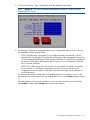
When the HP Network Storage System screen appears, enter qr to install the software.
Repeat steps 2–4 on each server.
Use a USB key
1.
2.
3.
Copy the ISO to a Linux system.
Insert a USB key into the Linux system.
Execute cat /proc/partitions to find the USB device partition, which is displayed as
dev/sdX. For example:
cat /proc/partitions
major minor #blocks
8
128
15633408
4.
name
sdi
Execute the following dd command to make USB the QR installer:
dd if=<ISO file name with path> of=/dev/sdi oflag=direct bs=1M
For example:
dd if=X9000-QRDVD-6.2.96-1.x86_64.iso of=/dev/sdi oflag=direct bs=1M
4491+0 records in
Installing the latest IBRIX X9000 software release
7
4491+0 records out
4709154816 bytes (4.7 GB) copied, 957.784 seconds, 4.9 MB/s
5.
6.
7.
Insert the USB key into the server to be installed.
Restart the server to boot from the USB key. (Press F11 and use option 3 ).
When the “HP Network Storage System” screen appears, enter qr to install the software.
Repeat steps 5–8 on each server and then go to the next section, “Starting the installation and
configuration.”
Starting the installation and configuration
Complete the following steps:
1. Boot the servers that will be in the cluster.
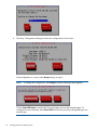
2. The setup wizard checks the network for an existing cluster. If a cluster is found, you will be
asked if you want to join an existing cluster or create a new cluster.
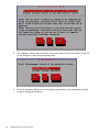
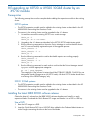
If there is not an existing cluster or you chose to create a new cluster, the setup process asks
for information about the server you are using. On the System Date and Time dialog box,
enter the system date (day/month/year) and time (in 24-hour format). Tab to the Time Zone
field and press Enter to display a list of time zones. Select your time zone from the list.
3.
8
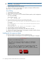
The Server Networking Configuration dialog box defines the server on bond0. Note the
following:
•
The hostname can include alphanumeric characters and the hyphen (–) special character.
It is a best practice to use only lowercase characters in hostnames; IBRIX issues can occur
with uppercase characters. Do not use an underscore (_) in the hostname.
•
The IP address is the address of the server on bond0.
Installing X9300 and X9320 systems
•
The default gateway provides a route between networks. If your default gateway is on a
different subnet than bond0, skip this field.
Later in this procedure, you can select either Web UI or ASCII text mode to complete the
installation. A gateway address is required to use the Web UI.
•
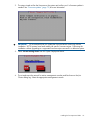
VLAN capabilities provide hardware support for running multiple logical networks over
the same physical networking hardware. IBRIX supports the ability to associate a VLAN
tag with a FSN interface. For more information, see the HP IBRIX X9000 Network Storage
System Network Best Practices Guide.
NOTE: If you see a message reporting that link-down networking issues were detected, select
Proceed.
4.
The Configuration Summary lists your configuration. Select Commit to continue the installation.
The setup wizard now configures the server according to the information you entered.
Starting the installation and configuration
9
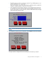
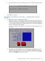
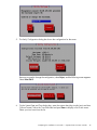
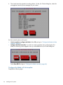
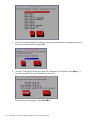
5.
Select a method to complete the installation:
•
Web UI over the network from a remote system. The URL for the IBRIX Getting Started
Wizard is displayed on the console when you select this option.
•
A local Web UI session on this console. Selecting this option launches the IBRIX Getting
Started Wizard from a web browser on this console.
•
ASCII text mode. This is a continuation of the menus you have been using.
IMPORTANT:
To configure separate cluster and user networks, you must use ASCII text mode.
IMPORTANT:
To use web UI, your cluster network must meet the following conditions:
•
Network bond0 was configured without errors.
•
Broadcast is enabled. The web UI relies on broadcast traffic.
•
The cluster has a single bond0 unified network for user/cluster traffic. (Using an external
management network for ILO traffic is okay.) The web UI assumes that a bond0 unified
network should be used throughout the cluster.
•
You entered a gateway IP address on the Server Setup screen.
If your cluster does not meet these conditions, select text mode to complete the installation.
If you would like to proceed with the Getting Started Wizard from some other laptop or desktop
connected to the network, select Install in graphical mode remotely. To proceed with the Getting
Started Wizard on this console, select Install in graphical mode at this console. If you are using
web UI, see “Configuring the cluster with the Getting Started Wizard (X9300/X9320 systems)”
(page 31).
If you are using text mode, go to the section corresponding to your network type.
10
•
Unified network. Configure the bond0 interface and the active management console (Fusion
Manager) on the server and, optionally, create a template for installing the remaining servers.
•
Separate cluster and user networks. Customize the bond0 cluster interface if needed, define
the bond1 user interface, and configure the active management console (Fusion Manager)
on the server. See “Completing the installation in text mode — separate cluster and user
networks” (page 19).
Installing X9300 and X9320 systems
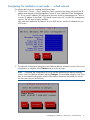
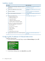
Completing the installation in text mode — unified network
To configure the first server, complete the following steps:
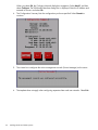
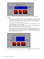
1. On the Form a Cluster — Step 2 dialog box, enter a name for the cluster and specify the IP
address and netmask for the Management Console IP (also called the Cluster Management
IP). This a virtual IP address (VIF) assigned to the entire cluster for management use. Think of
it as the “IP address of the cluster.” You should connect to this VIF in future GUI management
sessions. The VIF remains highly available.
Also enter the IP addresses and domain for your DNS servers, and the IP addresses for your
NTP servers.
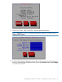
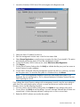
2.
The Network Configuration dialog box lists the Ethernet devices included in bond0. The bond0
configuration is complete; select Continue and go to the next step.
NOTE: If required, the configuration of bond0 can be modified at this step by selecting
bond0 in the list of devices and then selecting Configure. This should be necessary only if you
have a non-standard configuration and the slave devices chosen by the installer for bond0
are not correct for your environment.
Completing the installation in text mode — unified network
11
12
3.
The Configuration Summary lists the configuration you have specified. Select Commit to
continue.
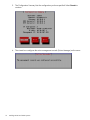
4.
The wizard now configures the active management console (Fusion Manager) on the server.
Installing X9300 and X9320 systems
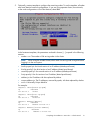
5.
Optionally, create a template to configure the remaining nodes. To use the template, all nodes
must have identical network configurations. If you are using separate cluster/user networks,
or the node configurations will not be identical, select Exit.
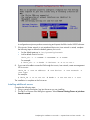
In the hostname templates, the parameters enclosed in braces ({...}) expand in the following
manner:
•
number num: The number of file serving nodes in the cluster.
NOTE: When using the number format, allow each file serving node to register before
logging in to the next system.
•
fourth-ip-quad ip4: the fourth section of an IP address (dotted quad format)
•
third-ip-quad ip3: the third section of an IP address (dotted quad format)
•
second-ip-quad ip2: the second section of an IP address (dotted quad format)
•
first-ip-quad ip1: the first section of an IP address (dotted quad format)
•
address ip: the IP address with dots replaced by dashes
•
reverse-address rip: The IP addresses, reversed by quads, with dots replaced by dashes
•
uuid: A Universally Unique Identifier
For example:
template: ib74s{fourth-ip-quad}
ip
hostname
192.168.74.3
ib74s3
template: ib74s{first-ip-quad}
ip
hostname
192.168.74.3
ib74s192
template: Noname-{address}
ip
hostname
192.168.74.3
Noname-192-168-74-3
template: Noname-{reverse-address}
ip
hostname
192.168.74.3
Noname-3-74-168-192
Completing the installation in text mode — unified network
13
A configuration script now performs some tuning and imports the LUNs into the X9000 software.
When the script is complete, you can install the remaining servers.
If you did not create a template, go to the next section.
If you created a template, go to “Installing additional servers using the template” (page 17).
Installing additional servers without the template
Complete the following steps:
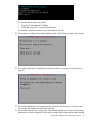
1. Using a console connection, log into the server you are installing. The Set IP or Discover FMs
dialog box appears. Select Discover Existing Clusters to join them from this console.
14
2.
The installation wizard scans the network for existing clusters and lists the clusters on the Join
Cluster dialog box. Select the appropriate cluster.
3.
The Verify Hostname dialog box lists a hostname generated from the management console.
Accept or change this hostname.
Installing X9300 and X9320 systems
4.
5.
6.
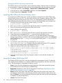
The Verify Configuration dialog box shows the configuration for the server. Select Commit to
continue.
On the Form a Cluster — Step 2 dialog box, enter the cluster name and specify the IP address
and netmask for the Management Console IP (also called the Cluster Management IP). Also
enter the IP addresses and domain for your DNS servers, and the IP addresses for your NTP
servers.
The Network Configuration dialog box lists the Ethernet devices included in bond0. The bond0
configuration is complete; select Continue and go to the next step.
NOTE: If required, the configuration of bond0 can be modified at this step by selecting
bond0 in the list of devices and then selecting Configure. This should be necessary only if you
have a non-standard configuration and the slave devices chosen by the installer for bond0
are not correct for your environment.
Completing the installation in text mode — unified network
15
7.
The Configuration Summary dialog box lists the configuration you specified. Select Commit
to apply the configuration.
8.
The wizard registers a passive Fusion Manager on the server, and then configures and starts
it.
The installation is complete.
16
Installing X9300 and X9320 systems
Installing additional servers using the template
Complete the following steps:
1. Using a console connection, log into the server you are installing. The Set IP or Discover FMs
dialog box appears. Select Discover Existing Clusters to join them from this console.
2.
The installation wizard scans the network for existing clusters and lists the clusters on the Join
Cluster dialog box. Select the appropriate Fusion Manager management console.
3.
The server you are installing is assigned the appropriate name from the template, plus the last
octet IP for a hostname. If necessary, you can change the hostname on the Verify Hostname
dialog box.
Completing the installation in text mode — unified network
17
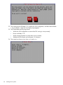
4.
The Verify Configuration dialog box shows the configuration for the server.
If the configuration is correct, select Accept and go to step 4.
NOTE:
To change the configuration, select Reject, and the following screen appears.
Choose Select FM Again to reselect the Fusion Manager and use the template again. To
configure the server manually, select Enter FM IP and use the procedure corresponding to your
network type.
18
Installing X9300 and X9320 systems
5.
The wizard registers a passive Fusion Manager on the server, and then configures and starts
it.
The installation is complete.
Completing the installation in text mode — separate cluster and user
networks
To configure the first server, complete the following steps:
1. On the Form a Cluster — Step 2 dialog box, enter a name for the cluster and specify the IP
address and netmask for the Management Console IP (also called the Cluster Management
IP). This a virtual IP address (VIF) assigned to the entire cluster for management use. Think of
it as the “IP address of the cluster.” You should connect to this VIF in future GUI management
sessions. The VIF remains highly available.
Also enter the IP addresses and domain for your DNS servers, and the IP addresses for your
NTP servers.
2.
The Network Configuration dialog box lists the Ethernet devices included in bond0. If the
devices are correct, go to step 3. If you have a non-standard configuration and the slave
devices chosen by the installer for bond0 are not correct for your environment, select bond0
and then select Configure to customize the interface.
Completing the installation in text mode — separate cluster and user networks
19
On the Edit Bonded Interface dialog box, enter the IP address and netmask and specify any
bond options. The slaves are selected by the system based on the following preference:
•
10G dual port PCI add-on card
•
1G quad port PCI add-on card
•
Embedded server network ports
Change the slave devices as necessary for your configuration.
When you select Ok, the Configuration Summary dialog box appears. Select Back and return
to the Network Configuration dialog box.
3.
20
Set up bond1. On the Network Configuration dialog box, select <Add Device>.
Installing X9300 and X9320 systems
On the Select Interface Type dialog box, select Ok to create a bonded interface.
On the Add Bonded Interface dialog box, enter bond1 as the name for the interface. Also
specify the appropriate options and slave devices. Use mode 6 bonding for a 1GbE network,
and mode 1 bonding for a 10GbE network.
Completing the installation in text mode — separate cluster and user networks
21
When you select Ok, the Configure Network dialog box reappears. Select bond1, and then
select Configure. The Edit Bonded Interface dialog box is displayed. Enter the IP address and
netmask for bond1 and select Ok.
22
4.
The Configuration Summary lists the configuration you have specified. Select Commit to
continue.
5.
The wizard now configures the active management console (Fusion Manager) on the server.
6.
The template does not apply when configuring separate cluster and user networks. Select Exit.
Installing X9300 and X9320 systems
A configuration script now performs some tuning and imports the LUNs into the X9000 software.
7.
If the bond0/cluster network is not routed and the bond1/user network is routed, complete
the following steps to define the default gateway for bond1:
•
Set the default gateway in /etc/sysconfig/network.
•
Add a default route for bond1:
ibrix_nic -r -n IFNAME -h HOSTNAME -A -R ROUTE
For example:
# ibrix_nic -r -n bond1 -h ibrix02a -A -R 10.10.125.1
8.
If you want to be able to access the FM through the bond1/user network, create a management
VIF for bond1:
ibrix_fm -c <VIF IP address> -d <VIF device> -n <VIF netmask> -V
<VIF type>
For example:
# ibrix_fm -c 10.10.125.101 -d bond1:1 -n 255.255.255.0 -v user
The installation is complete on the first server.
Installing additional servers
Complete the following steps:
1. Using a console connection, log into the server you are installing.
2. The Set IP or Discover FMs dialog box appears. Select Discover Existing Clusters to join them
from this console.
Completing the installation in text mode — separate cluster and user networks
23
24
3.
The installation wizard scans the network for existing clusters and lists the clusters on the Join
Cluster dialog box. Select the appropriate cluster.
4.
The Verify Hostname dialog box lists a hostname generated from the management console.
Accept or change this hostname.
Installing X9300 and X9320 systems
5.
The Verify Configuration dialog box shows the configuration for the server.
Because you need to change the configuration, select Reject, and the following screen appears.
Select Enter FM IP.
6.
On the System Date and Time dialog box, enter the system date (day/month/year) and time
(24-hour format). Tab to the Time Zone field and press Enter to display a list of time zones.
Select your time zone from the list.
Completing the installation in text mode — separate cluster and user networks
25
7.
The Server Networking Configuration dialog box defines the server on bond0. Note the
following:
•
The hostname can include alphanumeric characters and the hyphen (–) special character.
It is a best practice to use only lowercase characters in hostnames; uppercase characters
can cause issues with IBRIX software. Do not use an underscore (_) in the hostname.
•
The IP address is the address of the server on bond0.
•
The default gateway provides a route between networks. If your default gateway is on a
different subnet than bond0, skip this field.
Later in this procedure, you can select either Web UI or ASCII text mode to complete the
installation. A gateway address is required to use the Web UI.
•
8.
26
VLAN capabilities provide hardware support for running multiple logical networks over
the same physical networking hardware. IBRIX supports the ability to associate a VLAN
tag with a FSN interface. For more information, see the HP IBRIX X9000 Network Storage
System Network Best Practices Guide.
The Configuration Summary lists your configuration. Select Commit to continue the installation.
Installing X9300 and X9320 systems
9.
On the Join a Cluster – Step 2 dialog box, enter the requested information.
NOTE: Register IP is the Fusion Manager (management console) IP, not the IP you are
registering for this server.
10. The Network Configuration dialog box lists the Ethernet devices in bond0. If the devices are
correct, go to the next step. If the devices are not correct, select bond0 and then select Configure
to customize the interface.
Completing the installation in text mode — separate cluster and user networks
27
On the Edit Bonded Interface dialog box, enter the IP address and netmask, specify any bond
options, and change the slave devices as necessary for your configuration.
When you select Ok, the Configuration Summary dialog box appears. Select Back and return
to the Network Configuration dialog box.
11. Configure bond1. Select <Add Device> from the Network Configuration dialog box.
28
Installing X9300 and X9320 systems
On the Select Interface Type dialog box, select Ok to create a bonded interface.
On the Add Bonded Interface dialog box, enter bond1 as the name for the interface. Also
specify the appropriate options and slave devices. Use mode 6 bonding for a 1GbE network,
and mode 1 bonding for a 10GbE network.
Completing the installation in text mode — separate cluster and user networks
29
When you select Ok, the Configure Network dialog box reappears. Select bond1, and then
select Configure. The Edit Bonded Interface dialog box is displayed. Enter the IP address and
netmask for bond1, specify any bond options, and change the slave devices if necessary.
12. The Configuration Summary dialog box lists the configuration you specified. Select Commit
to apply the configuration.
13. The wizard registers a passive Fusion Manager on the server, and then configures and starts
it.
14. If necessary, complete the bond1 configuration on the server:
•
If the bond0/cluster network is not routed and the bond1/user network is routed, set the
default gateway in /etc/sysconfig/network.
•
On the active FM, set the default route for bond1:
ibrix_nic -r -n <bond> -h <hostname> -A -R <route>
For example:
ibrix_nic -r -n bond1 -h ibrix02a -A -R 10.10.125.1
The installation is complete.
30
Installing X9300 and X9320 systems
2 Configuring the cluster with the Getting Started Wizard
(X9300/X9320 systems)
The Getting Started Wizard configures the cluster in a few steps. Be sure to have the necessary IP
addresses available.
NOTE:
This wizard can be used only for X9300 and X9320 systems.
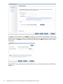
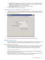
Running the wizard
The Cluster Settings page asks for information to identify your cluster. Enter a name for the cluster
and specify the Cluster Management IP address.
Running the wizard
31
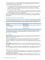
To update your license keys, click Update. Typically, you will need a license key for each server.
Download your licenses from the HP website and place them in a location that can be accessed
by this server. Use Browse to locate a license key and then click Add. Repeat this step for each
license key.
Enter the DNS server addresses and search domain for your cluster. Also enter your NTP server
addresses.
32
Configuring the cluster with the Getting Started Wizard (X9300/X9320 systems)
The wizard attempts to access the addresses that you specify. If it cannot reach an address, a
message such as Primary DNS Server Unreachable will be displayed on the screen.
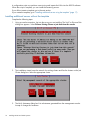
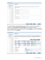
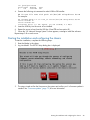
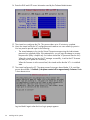
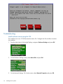
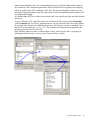
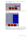
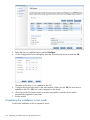
The File Servers page lists all servers the wizard found on your network. If the list includes servers
that do not belong in the cluster, select those servers and click Remove. If a server is not defined,
select the server and click Configure.
Running the wizard
33
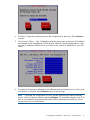
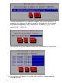
To configure a server, select the server on the File Servers page and click Configure. Enter the host
name and IP address of the server. If the wizard can locate the subnet masks and iLO IP address,
it will fill in those values.
If your cluster should include servers that were not listed on the File Servers page, configure an IP
address manually on the servers, using their local console setup screens. Then click Add on the
File Servers page to add the servers to the cluster. You can enter a single IP address on the Add
Servers dialog box, or you can enter a range of addresses and the wizard will locate all servers
with IP addresses in the range.
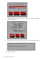
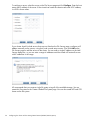
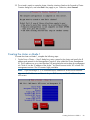
HP recommends that you create a single file system using all of the available storage. You can
create this file system on the Create a Default File System page. You can also create NFS and CIFS
shares on the file system.
34
Configuring the cluster with the Getting Started Wizard (X9300/X9320 systems)
f you create a CIFS share, you will need to configure the file serving nodes for CIFS and configure
authentication. You might also want to set certain CIFS parameters such as user permissions. Other
configuration options are also available for NFS shares. See the HP IBRIX X9000 Network Storage
System File System User Guide for more information.
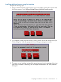
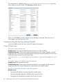
The Summary lists any warnings or other items noted during the post-installation checks. Click the
items to determine whether further action is needed.
Running the wizard
35
The wizard saves an installation log at /usr/local/ibrix/log/installtime.log on the
server where you ran the wizard. Click View Log to display the log.
When you click Finish to exit the wizard, the Fusion Manager is restarted. When the service is
running again, you can log into the GUI.
Troubleshooting the Getting Started Wizard
If you are unable to resolve an issue, contact HP support for assistance.
Cluster Settings page
The cluster name cannot be set
Probable cause: The command failed because of a timeout or other condition.
Troubleshooting steps: There may be network inconsistencies or an outage. Typically, a network
outage lasts only a few minutes. Check the network settings and retry the operation. You can also
use the following command to set the cluster name:
ibrix_fm_tune -S -o clusterName=<clusterName>, fusionPrimaryAddress=<Vif
add>
The cluster name and IP address cannot be retrieved
Probable cause: The command timed out.
Troubleshooting steps: There may be network inconsistencies or an outage. Usually a network
outage lasts only a few minutes. Relaunch the wizard and try the operation again.
The VIF for the primary file server cannot be registered
Probable cause:
36
•
The specified IP address is already assigned to another server.
•
The Fusion Manager registration failed for the primary file server.
•
The segment server registration failed for the primary file server.
Configuring the cluster with the Getting Started Wizard (X9300/X9320 systems)
Troubleshooting steps:
1. Relaunch the wizard, go to the Cluster Settings page, and click Next to retry the operation.
If the operation fails again, run ifconfig bond0:0. If the output is empty, use the following
command to set the VIF on the server:
ibrix_fm -c <VIF IP address> -d bond0:0 -n <VIF Netmask> -v cluster
2.
Check the status of the Fusion Manager registration on the primary server:
ibrix_fm –i
If the output is FusionServer: fusion manager name not set! (active, quorum
is not configured) and the output of ibrix_fm –l is empty, use the following command
to perform the Fusion Manager registration:
ibrix_fm -R hostname -I ipaddress
3.
Run the ibrix_server –l command. If there is no output, use the following command to
register the segment server:
/usr/local/ibrix/bin/register_server -p -c bond0 -n <hostname> -a
none -H /usr/local/ibrix <VIF IP address>
4.
Restart the server:
/usr/local/ibrix/bin/init/ibrix_server start
If the registration continues to fail, use the text-based installation method to set the VIF. If that fails,
QR the system.
DNS/FTP page
DNS and /NTP cannot be set
Probable cause:
•
The specified DNS/NTP IP addresses are not valid.
•
The specified domain name is not valid.
•
A network outage or connectivity situation occurred.
Troubleshooting steps:
•
Determine whether the specified IP addresses are valid and can be pinged. Run the following
command:
dig +short @ <DNS server IP>
If the output is empty or the connection times out, contact the administrator for the DNS/NTP
server. Then relaunch the wizard to configure the DNS/NTP settings.
•
If the DNS/NTP IP addresses are valid, the wizard will configure them. However, if you want
to set DNS and NTP manually, use the following Linux command to set the NTP server settings:
ntpdate –u <NTP server IP> )
To set the DNS server, edit the /etc/resolv.conf file, where:
◦
search <domainname.com>: The search list is normally determined from the local
domain name. By default, it contains only the local domain name.
◦
nameserver <Name-server-IP-address>: Point to your name server or the ISP
name server. You can list up to three name servers.
For example:
search mydomain.com
nameserver 201.52.1.10
nl
nl
Troubleshooting the Getting Started Wizard
37
nameserver 202.52.1.11
If the operation still fails, there may be network inconsistencies or an outage. Typically, a network
outage lasts only a few minutes. Try the operation later. If the operation continues to fail, contact
your network administrator.
DNS/NTP information cannot be retrieved
Probable cause: The command timed out.
Troubleshooting steps: The network is experiencing inconsistencies or an outage. Usually a network
outage last only a few minutes. Relaunch the wizard and start the operation again.
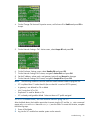
File Servers page
No servers are detected
Probable cause:
•
The discovery service is not running on the servers.
•
The X9000 version on the servers does not match the version on the primary (Active ) server.
•
The servers belong to another cluster.
•
Multicast is not enabled on the servers.
•
The network is behaving inconsistently, causing a timeout.
Troubleshooting steps:
•
Check the system type. Run the following command on the servers you expected to discover:
/opt/hp/platform/bin/hpsp_srvid
If the system type is X9720, the servers will not be displayed. The installation does not support
X9720 systems.
•
Check the status of the discovery service on all expected servers. (If the expected servers do
not have an IP address, use the ILO to check the status.)
service ibrix_discovery status
If the discovery service is stopped, restart the service:
service ibrix_discovery start
Then relaunch the wizard and go to the File Servers page.
NOTE:
•
If the discovery does not start, files may be missing or deleted. QR the system.
Check the X9000 software version on the servers. (If the expected servers do not have an IP
address, use the ILO to check the version.)
ibrix_version –l
If the major and minor version numbers on the expected servers do not match the version on
the active server, update the X9000 software on the expected servers. Then relaunch the
wizard, go to the File Servers page, and check for the servers.
•
Determine whether multicast broadcasting is enabled on the active server:
ibrix_discovery -d
If the command does not discover any nodes, multicast broadcasting may be disabled. If so,
enable multicast on the server, relaunch the wizard, go to the File Servers page, and check
for the servers. You can also use the text-based installation method to form the cluster.
•
38
Check the network connection. The discovery period for servers is approximately one minute.
If the active server does not receive a response within that time, the servers will not be
Configuring the cluster with the Getting Started Wizard (X9300/X9320 systems)
displayed. This situation could be caused by network inconsistencies or an outage. Usually a
network outage lasts only a few minutes. Try relaunching the wizard and revisiting this page.
If the operation continues to fail, use the text-based installation method to form the cluster.
Server registration fails with “Error: Registering server” or “Error: Passive FM”
Probable cause:
•
The operation failed when checking and configuring network details for a passive server.
•
The hostname is not valid and cannot be reached.
•
The operation failed when registering the server with the active Fusion Manager.
•
The operation failed when setting passive mode on the server.
•
The operation failed when setting nofailover mode on the server.
•
The operation failed when restarting the Fusion Manager.
•
The operation failed because of a timeout or other condition.
Troubleshooting steps:
1. Try to ping the server. If the server cannot be reached, the network settings on that server may
have failed. This can be due to temporary connectivity conditions. Try using the iLO to assign
network details such as the IP address and hostname and then launch the wizard again. If
connectivity is restored, the server will be discovered as already configured, and it can be
used to form the cluster.
2. Check the status of the Fusion Manager registration on the primary server:
ibrix_fm –i
If the output is FusionServer: fusion manager name not set! (active, quorum
is not configured) and the output of ibrix_fm –l is empty, use the following command
to perform the Fusion Manager registration:
ibrix_fm -R hostname -I ipaddress
3.
Run the ibrix_server –l command. If there is no output, use the following command to
register the segment server:
/usr/local/ibrix/bin/register_server -p -c bond0 -n <hostname> -a
none -H /usr/local/ibrix <VIF IP address>
4.
Restart the server:
/usr/local/ibrix/bin/init/ibrix_server start
Alternatively, you can use the text-based installation method to perform the registration, but you
will need to enable the HA configuration after the registration is complete.
If the registration continues to fail, there may be a network inconsistency or outage. A network
outage usually lasts only a few minutes. If the operation continues to fail, contact your network
administrator.
An HA pair cannot be configured
Probable cause:
•
Network configuration failed on the server.
•
The command timed out.
Troubleshooting steps:
•
Try to ping the server. If you cannot reach the server, the network settings on the server may
have failed. This can be due to temporary connectivity conditions. Use the iLO to assign
Troubleshooting the Getting Started Wizard
39
network details such as the IP address and hostname, relaunch the wizard, and try to set the
HA pair again.
If the operation still fails, use the following command to set the HA pair:
ibrix_server -b -h SERVERNAME1,SERVERNAME2
•
Network inconsistencies or an outage could cause the wizard to fail. Usually a network outage
lasts only a few minutes. Relaunch the wizard, go to the File Servers page, and click Next to
try to set HA pair again.
If the operation continues to fail, QR the system and retry the operation.
An HA backup server cannot be configured
Probable cause:
•
No storage was detected.
•
A backup candidate server was not listed.
Troubleshooting steps:
•
If the backup candidate server is not listed on the screen, restart the listener on that server
using service ibrix_discovery restart, relaunch the wizard, and go to the File
Servers page.
•
Run the ibrix_version –l command and check the X9000 software version on the backup
server. If the version does not match the version on the active server, update the X9000
software and QR the system again.
•
If the backup candidate server is listed but the Back-up not found error occurs, possibly
storage was not detected on either or both of the servers, or the storage was detected but it
did not match with the expected HA pair. If so, run the appropriate command on both servers:
X9730 systems: ccu show controllers all
X 9300/X9320 systems: multipath -ll
If the output matches on both servers, restart the discovery service:
service ibrix_discovery restart
Then relaunch the wizard and go to the File Servers page.
If the output does not match, the two servers are not considered to be an HA pair. Check the
storage settings and mapping to the controllers/servers.
If the HA pair detection fails after taking these actions, use the text-based installation method to
form the cluster.
A power source cannot be added
Probable cause:
•
The iLO IP address is not reachable.
•
The command timed out.
Troubleshooting steps:
•
Use the following command to determine whether the iLO can be accessed:
ping <iLO address>
If the iLO cannot be reached, use the route command to check the gateway used for the
server. Both the server and iLO should be on the same network. After verifying this, relaunch
the wizard and go to the File Servers page. Click Next to add the power source again.
If the operation still fails, use the following command to set the power source:
40
Configuring the cluster with the Getting Started Wizard (X9300/X9320 systems)
ibrix_powersrc -a -t ilo -h HOSTNAME -I IPADDR [-u USERNAME -p
PASSWORD] [-s]
•
If the network is experiencing inconsistencies or an outage, the wizard can fail to add the
power source. Typically, a network outage lasts only a few minutes. Relaunch the wizard, go
to the File Servers page, and click Next to try to add the power source again.
If the operation continues to fail, QR the system again and retry the operation.
Bond creation fails with “Error: Fetching bond details”
Probable cause:
•
The bond0 device is not present on the server.
•
The operation to get the bond details failed.
Troubleshooting steps:
•
Use the ifconfig bond0 command to check for bond0. If the bond is not present, restart
the discovery service:
service ibrix_discovery restart
•
If restarting the discovery service fails, run the /opt/hp/platform/bin/hpsp_srvid
script and verify that the system type is not X9720. The installation does not support X9720
systems.
•
The discovery service does not create the bond if network configurations already exist on
eth0. If network settings exist on the eth0 port, remove the network configuration and then
restart the discovery service.
•
Check the value of the LISTENER_BONDED_INTERFACE entry in the /usr/local/ibrix/
bin/listener.conf file. If it is not bond0, edit the file, setting the value for
LISTENER_BONDED_INTERFACE to bond0, and then restart the discovery service:
service ibrix_discovery restart
•
If the previous step fails to create the bond0 interface, either use the text-based installation
method to perform the network settings or create the bond interface on the server using the
following command:
/usr/local/ibrix/autocfg/bin/create_bonds -d 0 <Bond Mode> bond0
<eth port(s)>
Restart the discovery application. To determine values for the bond mode and Ethernet ports,
contact HP Support or your network administrator, or follow these steps:
◦
On X9730 systems, create the bond on internal NIC ports.
◦
On X9300/X9320 systems, create the bond on external NIC ports. To detect the external
NIC ports connected to the server, run the following command to list all available NIC
ports:
ip add| grep eth
Run the following command to list only internal NIC ports:
dmidecode | grep "MAC address”
The external NIC ports appear on the ipadd output but not on the dmidecode output.
Troubleshooting the Getting Started Wizard
41
Use ethtool <eth port> to detect the speed information. The port value for X9300/X9320
systems is detected as described in the previous step. For X9730 systems, the ports are internal.
•
◦
If the speed of the NIC ports selected for bond creation is 10GB, use any two NIC ports
in bond mode 1.
◦
If the speed of the NIC ports selected for bond creation is 1GB, use four NIC ports in
bond mode 6.
If these steps do not resolve the condition, use the text-based installation method to form the
cluster.
Create a Default File System page
The default file system cannot be created
Probable cause:
•
The file system mount operation failed.
•
The specified volume group name already exists.
•
The storage is not preformatted properly.
Troubleshooting steps:
•
Determine if the file system was actually created. Run the ibrix_fs –l command. If the file
system exists but is not mounted, use the GUI or the following command to mount the file
system:
ibrix_mount -f FSNAME [-o { RW | RO } ] [-O MOUNTOPTIONS] [-h
HOSTLIST] -m MOUNTPOINT
•
The storage might be unavailable. To determine the storage exposed to the server, run the
following command to discover devices:
ibrix_pv –a
List the discovered physical devices:
ibrix_pv –l
If the output of ibrix_pv –l is not empty, relaunch the wizard, go to the Create a Default
File System page, and create the file system. If the output is empty, no storage is available to
create the file system. Add storage to the server and run the previous commands again to
make the storage available for the file system.
•
The storage exposed to the servers might be in an inconsistent state. Preformat the storage
before trying to create the default file system. Complete the following steps on any server:
1. On the GUI, unmount the file system created in a previously formed cluster.
2. Delete all shares and the file system.
3. Use putty or ssh to connect to each node you need to QR and run following commands:
a. Reinitialize the physical volume so that it can be used by LVM. A new physical volume
is not created.
pvcreate -ff device path
For example:
pvcreate -ff /dev/sda
b.
Preformat the device:
/usr/local/ibrix/bin/preformat_segment -d device path
For example:
/usr/local/ibrix/bin/preformat_segment -d /dev/sda
42
Configuring the cluster with the Getting Started Wizard (X9300/X9320 systems)
QR the preformatted systems.
An NFS/CIFS share cannot be created
Probable cause:
•
The server on which the file system is mounted is not available for share creation.
•
The storage configuration is incorrect.
Troubleshooting steps:
Run the ibrix_fs –l command to determine whether the file system was actually created. If the
file system exists but is unmounted, use the GUI or the following command to mount the file system:
ibrix_mount -f FSNAME [-o { RW | RO } ] [-O MOUNTOPTIONS] [-h HOSTLIST]
-m MOUNTPOINT
After mounting the file system on the servers, use the GUI share creation wizard or a CLI command
to create the export or share.
Create a NFS export:
ibrix_exportfs -f FSNAME -h HOSTLIST -p
CLIENT1:PATHNAME1,CLIENT2:PATHNAME2, [ -o "OPTIONS"] [-b]
Create a CIFS share:
ibrix_cifs -a -f FSNAME -s SHARENAME -p SHAREPATH [-D SHAREDESCRIPTION]
[-S SETTINGLIST] [-h HOSTLIST]
Check the output of the appropriate command to verify that the export or share was created:
•
ibrix_exportfs –l (For NFS export)
•
ibrix_cifs -i (For CIFS shares)
If the NFS or CIFS share still cannot be created, preformat the storage. See “The default file system
cannot be created” (page 42).
Troubleshooting the Getting Started Wizard
43
3 Installing X9730 systems
The system is configured at the factory as follows:
•
X9000 File Serving Software 6.1 is installed on the servers.
•
LUNs are created and preformatted on the X9730 CX storage system.
•
Depending on the system size, the X9730 system is partially or totally preracked and cabled.
You will need the following information when you perform the installation:
•
IP addresses as specified in “IP address requirements” (page 45).
•
The administrator passwords for OA and VC. The default passwords are on the labels affixed
to the back of the chassis.
If you are performing the installation on an existing cluster, ensure that the same version of the
X9000 software is installed on all nodes.
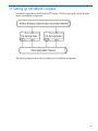
X9730 network layouts
The X9730 supports four networking layouts. The default is to use a single, unified network for all
cluster and user traffic. The other layouts provide a dedicated management network, a user/cluster
network, and, optionally, additional user networks. To use a network layout other than the default,
you need to specify the number of networks needed when you run the X9730 Setup Wizard.
NOTE:
Use layout 2 when adding an X9730 system to an existing 2-network IBRIX cluster.
See the HP IBRIX X9000 Network Storage System Network Best Practices Guide for detailed
information about the network layouts.
Table 1 Supported X9730 network layouts
Layout
Description
Number of
networks
Network
name
Ethernet
devices
Bond speed
1
Unified network (default)
1
bond0
eth0, eth3
10GB
2
Dedicated management network
2
bond0
eth0, eth3
1GB
bond1
eth1, eth2
9GB
bond0
eth0, eth3
1GB
User/cluster network
bond1
eth1, eth2
4.5GB
User2 network
bond2
eth4, eth5
4.5GB
bond0
eth0, eth3
1GB
User/cluster network
bond1
eth1, eth2
3.5GB
User2
bond2
eth4, eth5
3.5GB
User3
bond3
eth6, eth7
2GB
User/cluster network
3
4
44
Dedicated management network
Dedicated management network
Installing X9730 systems
3
4
IMPORTANT: In previous releases, the X9720 system shipped with access to the management,
user and cluster networks through a single FSN bond. The field setup moved the user and cluster
network access to a separate bond once the connection between a FSN and the customer network
was established.
X9730 systems default to a unified network configuration that places the chassis management
components on one subnet and the user/cluster components on a separate subnet. File serving
nodes are configured to access the user, cluster, and management networks through a single bond
attached to the user/cluster subnet. File serving node access to the components on the management
subnet requires a route in the customer network that connects the management and user/cluster
subnets.
IMPORTANT: The default unified network layout requires the customer to configure a router to
provide a level-3 route that connects the user/cluster subnet and the management subnet. The setup
process will not complete if the level-3 route is not in place for system installation. During the setup
process, the installer software makes sure that it can ICMP ping the OA to verify the route between
the user/cluster and management subnets. If it is unsuccessful, the installer software prompts the
user to correct the problem before proceeding.
IP address requirements
You will need the following IP addresses when you perform the installation for the unified network.
The HP IBRIX X9000 Network Storage System Network Best Practices Guide describes the
components in more detail, and also lists IP address requirements for the other supported network
layouts.
Table 2 IP addresses for unified network layout
Maximum number of
addresses
Component
Subnet
Minimum number of addresses
Cluster management VIF
user/cluster
1 (one virtual IP address to assign to the entire
cluster for management use)
1
User VIF
user/cluster
2 ( virtual IP address for failover)
Variable. At least 1
per node (16 included
in total)
File serving nodes
user/cluster
2 (one IP address per server to assign to the
network bond)
16
iLO
management
16
16
Interconnect bays
management
8
8
OA module
management
2 (OA primary and secondary)
2
31 for minimum configuration
59 for maximum
configuration
You also need to provide the IP addresses of the DNS servers, NTP servers, and, optionally, the
default gateway.
HP recommends that you use sequential addresses for the blades, iLOs, and Interconnect.
IP address requirements
45
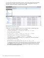
Installation checklist
Step
Task
More information
1.
Configure active and standby IP addresses for Onboard
Administrator
“Configuring OA1 IP addresses for Onboard
Administrator” (page 46)
2.
Install the latest IBRIX X9000 software release
“Installing the latest IBRIX X9000 software release”
(page 48)
3.
Perform the installation
“Starting the installation and configuring the
chassis” (page 49)
4.
Set up virtual IP addresses for client access
“Configuring virtual interfaces for client access”
(page 80)
5.
Perform post-installation tasks:
“Post-installation tasks” (page 77)
• Update license keys if needed
• Enable High Availability
• Configure Ibrix Collect
• Configure HP Insight Remote Support
• Create file systems if not already configured
Optionally, also configure the following features:
• NFS, CIFS, HTTP/HTTPS, FTP/FTPS shares
• Remote replication
• Data retention and validation
• Antivirus support
• Software snapshots
• Data tiering
• NDMP Backup Protocol Support
6.
Configure X9000 clients for Linux or Windows (optional)
“Adding Linux and Windows X9000 clients”
(page 83)
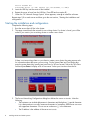
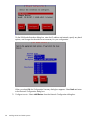
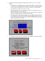
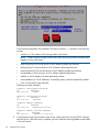
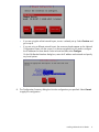
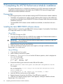
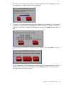
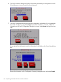
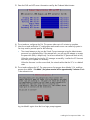
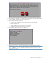
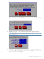
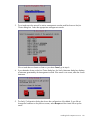
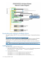
Configuring OA1 IP addresses for Onboard Administrator
Complete the following steps:
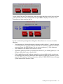
1. From the Main Menu of the Insight Display, navigate to Enclosure Settings and press OK.
2.
46
On the Enclosure Settings screen, select Active OA and press OK.
Installing X9730 systems
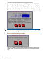
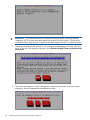
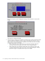
3.
On the Network Settings: OA1 Active screen, select Network Properties and press OK.
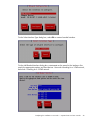
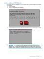
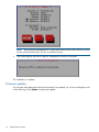
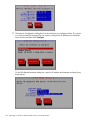
4.
On the Change OA Network Properties screen, set Enclosure IP to Enable and press OK to
Accept.
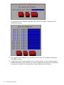
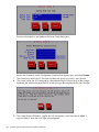
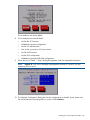
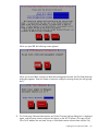
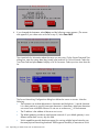
5.
On the Network Settings:OA1 Active screen, navigate to Active IPv4 and press OK.
6.
On the Change:OA1 Network Mode screen, change DHCP to Static and press OK to Accept.
Configuring OA1 IP addresses for Onboard Administrator
47
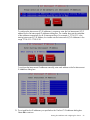
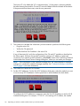
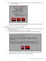
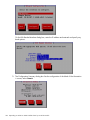
7.
On the Change: OA1 IP Address screen, set the IP address, subnet mask, and gateway
(optional) and Accept the changes.
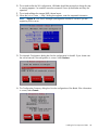
8.
On the Network Settings: OA1 Active screen, select Accept All and press OK.
9.
10.
11.
12.
On the Enclosure Settings screen, select Standby OA or OA2 and press OK.
On the Network Settings:OA2 screen, navigate to Active IPv4 and press OK.
Set the IP address, subnet mask, and gateway (optional) and Accept the changes.
Back on the Network Settings:OA2 screen, navigate to Accept All and press OK.
The Main Menu reappears and the procedure is complete.
Installing the latest IBRIX X9000 software release
Obtain the latest 6.1 release from the IBRIX X9000 software dropbox. Download the Quick Restore
ISO image and transfer it to a DVD or USB key.
Use a DVD
1.
2.
Burn the ISO image to a DVD.
Insert the Quick Restore DVD into a USB DVD drive cabled to the Onboard Administrator or
to the Dongle connecting the drive to the front of the blade.
IMPORTANT: Use an external USB drive that has external power; do not rely on the USB
bus for power to drive the device.
3.
4.
Restart the server to boot from the DVD-ROM.
When the HP Network Storage System screen appears, enter qr to install the software.
Repeat steps 2–4 on each server.
Use a USB key
1.
2.
3.
48
Copy the ISO to a Linux system.
Insert a USB key into the Linux system.
Execute cat /proc/partitions to find the USB device partition, which is displayed as
dev/sdX. For example:
Installing X9730 systems
cat /proc/partitions
major minor #blocks
8
128
15633408
4.
name
sdi
Execute the following dd command to make USB the QR installer:
dd if=<ISO file name with path> of=/dev/sdi oflag=direct bs=1M
For example:
dd if=X9000-QRDVD-6.2.96-1.x86_64.iso of=/dev/sdi oflag=direct bs=1M
4491+0 records in
4491+0 records out
4709154816 bytes (4.7 GB) copied, 957.784 seconds, 4.9 MB/s
5.
6.
7.
Insert the USB key into the server to be installed.
Restart the server to boot from the USB key. (Press F11 and use option 3 ).
When the “HP Network Storage System” screen appears, enter qr to install the software.
Repeat steps 5–8 on each server.
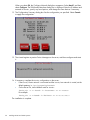
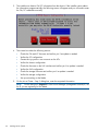
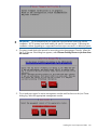
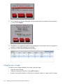
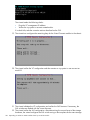
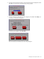
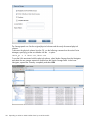
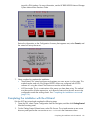
Starting the installation and configuring the chassis
To start the installation, complete the following steps:
1. Boot the blades in the cluster.
2. Log into blade1. The X9730 Setup dialog box is displayed.
3.
The setup wizard verifies the firmware on the system and notifies you if a firmware update is
needed. See “Firmware updates” (page 72) for more information.
Starting the installation and configuring the chassis
49
IMPORTANT: HP recommends that you update the firmware before continuing with the
installation. X9730 systems have been tested with specific firmware recipes. Continuing the
installation without upgrading to a supported firmware recipe can result in a defective system.
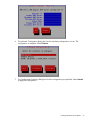
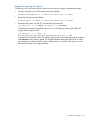
4.
The setup wizard checks the network for an existing cluster. If a cluster is found, you will be
asked if you want to join an existing cluster or create a new cluster.
If there is not an existing cluster or you chose to a new cluster, the setup wizard asks for
information about the blade you are using. On the System Date and Time dialog box, enter
the system date (day/month/year) and time (24-hour format). Tab to the Time Zone field and
press Enter to display a list of time zone. Then select your time zone from the list.
50
Installing X9730 systems
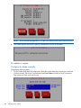
5.
The Server Networking Configuration dialog box defines the server on bond0. Note the
following:
•
The hostname can include alphanumeric characters and the hyphen (–) special character.
It is a best practice to use only lowercase characters in hostnames; uppercase characters
can cause issues with IBRIX software. Do not use an underscore (_) in the hostname.
•
The IP address is the address of the server on bond0.
•
The default gateway provides a route between networks. If your default gateway is on a
different subnet than bond0, skip this field.
Later in this procedure, you can select either Web UI or ASCII text mode to complete the
installation. A gateway address is required to use the Web UI.
•
6.
VLAN capabilities provide hardware support for running multiple logical networks over
the same physical networking hardware. IBRIX supports the ability to associate a VLAN
tag with a FSN interface. For more information, see the HP IBRIX X9000 Network Storage
System Network Best Practices Guide.
The Configuration Summary lists your configuration. Select Commit to continue the installation.
Starting the installation and configuring the chassis
51
The wizard now sets up the blade based on the information you entered.
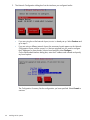
7.
The setup wizard next configures the chassis on the X9730 system. See the HP IBRIX X9000
Network Storage System Network Best Practices Guide for detailed information about the
chassis components. (This step will fail if the OA IP address has not been set up or if the blade
cannot communicate with the OA.) The Active Virtual Connect is by default the Virtual Connect
in interconnect bay 1. If the system is at factory defaults, the administrator passwords for OA
and Virtual Connect are on the labels affixed to the back of the chassis. If the passwords have
been reset, enter the new passwords.
IMPORTANT: If you are using the default unified network layout, select OK on the Confirming
Onboard Administrator and Virtual Connect Settings dialog box and go to step 8. To use a
different network layout, press F2.
When you press F2, the following screen appears.
When you answer Yes to configure a dedicated management network, the following screen
appears. Specify the number of networks for your layout on the Get Total Networks dialog
box.
52
Installing X9730 systems
8.
The wizard now validates the information you have entered. It performs the following tests:
•
Pings the active OA.
•
Verifies the OA password.
•
Verifies that that OA at that IP address is the active OA.
If any of these tests fail, verify the configuration of the OA and VC modules as described on
the failure report displayed on the GUI. If you need to re-enter the IP address for the OA, select
Back to return to the Confirming Onboard Administrator and Virtual Connect Settings dialog
box, where you can make your changes.
NOTE: If the initialization of the credential manager fails, the GUI displays a message asking
you to initialize the credential manager manually. See “Credential Manager initialization
failed” (page 76) for more information.
9. The wizard now verifies the OA firmware.
10. Set the iLO IP addresses. On the Get iLO IP Addresses dialog box, select the method you want
to use to set up iLO IP addresses. Use the space bar to select/deselect the check boxes.
To configure the iLO IP addresses in sequence, enter the first iLO IP address on the Set iLO IP
Addresses dialog box. For example, if 172.16.3.1 is the starting iLO IP address, the installer
sets the iLO IP addresses in the range 172.16.3.1 to 172.16.3.16 by incrementing 1 to the
last octet of the IP address.
Starting the installation and configuring the chassis
53
To configure the iLO IP addresses manually, enter each iLO IP address on the Enter iLO IP
Addresses dialog box.
11. The wizard lists the IP addresses you specified on the Confirm iLO IP Addresses dialog box.
Select Ok to continue.
12. Configure the chassis interconnect bays (VCs and SAS switches). On the Get Interconnect IP
Addresses dialog box, specify whether you want to configure the Interconnect (IC) IP addresses
in sequence or manually. Use the space bar to select/deselect the check boxes.
54
Installing X9730 systems
To configure the Interconnect (IC) IP addresses in sequence, enter the first Interconnect (IC) IP
address on the Set Interconnect IP Addresses dialog box. The installer then sets the remainder
of the addresses sequentially for all 8 interconnect bays. For example, if 172.16.3.21 is the
starting Interconnect (IC) IP Address, the installer sets the Interconnect (IC) IP Addresses in the
range 172.16.3.21–172.16.3.28.
To configure the Interconnect IP addresses manually, enter each address on the Set Interconnect
IP Addresses dialog box.
13. The wizard lists the IP addresses you specified on the Confirm IC IP Addresses dialog box.
Select Ok to continue.
Starting the installation and configuring the chassis
55
14. Enter the DNS and NTP server information used by the Onboard Administrator.
15. The wizard now configures the OA. This process takes up to 45 minutes to complete.
16. Next, the wizard verifies the VC configuration and creates a new user called hpspAdmin.
You may need to provide input for the following:
•
The wizard attempts to log into the Virtual Connect manager using the Administrator
password you supplied earlier. If the attempt fails, you can retry the attempt or re-enter
the password. (Retry is helpful only if a timeout caused the VC password check to fail.)
When the wizard can log into the VC manager successfully, it verifies the VC firmware
and asks you to update it if necessary.
When the firmware is at the correct level, the wizard verifies that the VC is in a default
state.
17. The wizard configures the VC. The setup process first powers down blades 2–16, and then
powers down blade 1. On blade 1, the power remains off for approximately 3 minutes. Blade
1 then reboots twice.
Log into blade1 again when the Linux login prompt appears.
56
Installing X9730 systems
The wizard makes the following checks:
•
Pings the VC management IP address.
•
Verifies the hpspAdmin account created earlier.
If a check fails, take the corrective actions described on the GUI.
18. The wizard now configures the remaining bays for the Virtual Connect modules in the chassis.
19. The wizard verifies the VC configuration and then creates an hpspAdmin user account on
each iLO.
20. The wizard validates the VC configuration and verifies the SAS firmware. If necessary, the
SAS switches are flashed with the correct firmware.
21. The wizard verifies the SAS configuration. After determining the correct layout of the storage
hardware, the wizard configures the SAS switch zoning so that couplets see the same storage.
Starting the installation and configuring the chassis
57
22. The wizard powers off blades 2–16, applies the SAS configuration, and then reboots blade
1. Log into blade 1 when the Linux login prompt appears.
23. The wizard takes the following actions:
•
Verifies the SAS configuration to ensure that SAS zoning is set up correctly
•
Powers on blades 2–16
•
Verifies storage firmware to ensure that is set up correctly
•
Validates the LUN layout and configures it if necessary
24. The wizard now forms bond0 from eth0 and eth3.
58
Installing X9730 systems
25. The wizard is ready to create the cluster. Note the situations listed on the Proceed to Cluster
Creation dialog box, and select Exit if they apply to you. Otherwise, select Proceed.
Creating the cluster on blade 1
To create the cluster on blade 1, complete the following steps:
1. On the Form a Cluster — Step 2 dialog box, enter a name for the cluster and specify the IP
address and netmask for the Management Console IP (also called the Cluster Management
IP). This IP address runs on a virtual interface (VIF) assigned to the entire cluster for management
use. Think of it as the “IP address of the cluster.” You should connect to this VIF in future GUI
management sessions. The VIF remains highly available.
NOTE:
If you are using a 2, 3, or 4 network layout, install this IP on the bond1 network.
Also enter the IP addresses and domain for your DNS servers, and the IP addresses for your
NTP servers.
Creating the cluster on blade 1
59
2.
The Network Configuration dialog box lists the interfaces you configured earlier.
•
If you are using the unified network layout, bond0 is already set up. Select Continue and
go to step 3.
•
If you are using a different network layout, the necessary bonds appear on the Network
Configuration screen with the correct eth devices assigned, but you need to configure
the IP addresses for those bonds. Select a bond and then select Configure.
On the Edit Bonded Interface dialog box, enter the IP address and netmask and specify
any bond options.
The Configuration Summary lists the configuration you have specified. Select Commit to
continue.
60
Installing X9730 systems
NOTE: Ensure that the Management IP is on the same subnet as the cluster network
(bond0 for the unified network layout; bond1 for all other layouts).
3.
The wizard now configures the active management console (Fusion Manager) on this blade.
4.
Optionally, create a template to configure the remaining nodes. The template is useful only if
all of the blades have identical network configurations, such as in the unified network.
Creating the cluster on blade 1
61
In the hostname templates, the parameters enclosed in braces ({...}) expand in the following
manner:
•
number num: The number of file serving nodes in the cluster.
NOTE: When using the number format, allow each file serving node to register before
logging in to the next system.
•
fourth-ip-quad ip4: the fourth section of an IP address (dotted quad format)
•
third-ip-quad ip3: the third section of an IP address (dotted quad format)
•
second-ip-quad ip2: the second section of an IP address (dotted quad format)
•
first-ip-quad ip1: the first section of an IP address (dotted quad format)
•
address ip: the IP address with dots replaced by dashes
•
reverse-address rip: The IP addresses, reversed by quads, with dots replaced by dashes
•
uuid: A Universally Unique Identifier
Following are some examples:
template: ib74s{fourth-ip-quad}
ip
hostname
192.168.74.3
ib74s3
template: ib74s{first-ip-quad}
ip
hostname
192.168.74.3
ib74s192
template: Noname-{address}
ip
hostname
192.168.74.3
Noname-192-168-74-3
template: Noname-{reverse-address}
ip
hostname
192.168.74.3
Noname-3-74-168-192
5.
62
A configuration script now performs some tuning, imports the LUNs into the X9000 software,
and sets up HA. When the script is complete, you can install the remaining blades as described
in the next section.
Installing X9730 systems
Installing additional X9730 blades
Use this procedure to install blades 2–16 on an X9730 system. Complete the following procedure
on each blade:
1. Log into the blade.
2. The X9730 Setup dialog box is displayed.
3.
The wizard verifies the firmware on the system and notifies you if a firmware update is needed.
IMPORTANT: HP recommends that you update the firmware before continuing with the
installation. X9730 systems have been tested with specific firmware recipes. Continuing the
installation without upgrading to a supported firmware recipe can result in a defective system.
Installing additional X9730 blades
63
4.
The wizard scans the network for existing clusters. On the Join Cluster dialog box, select the
management console (Fusion Manager) for your cluster.
You have several options at this point:
•
Use the template to configure the blade. Select Ok, and go to “Configure the blade with the
template” (page 64).
•
Configure the blade manually. If you did not create a template when configuring the first
blade, the following screen appears when you select Ok on the Join Cluster dialog box:
Select Enter FM IP and go to “Configure the blade manually” (page 68).
Configure the blade with the template
Complete the following steps:
64
Installing X9730 systems
1.
The blade you are installing is assigned the appropriate name from the template, plus the last
octet IP for a hostname. If necessary, you can change the hostname on the Verify Hostname
dialog box.
2.
The Verify Configuration dialog box shows the configuration for this blade.
If the configuration is correct, select Accept and go to step 3.
NOTE:
To change the configuration, select Reject, and the following screen appears.
Choose Select FM Again to reselect the Fusion Manager and use the template again. To
configure the node manually, select Enter FM IP and and go to “Configure the blade manually”
(page 68).
Installing additional X9730 blades
65
3.
The installer now obtains OA/VC information from the chassis. If the installer cannot obtain
the information programmatically, the following screen will appear and you will need to enter
the OA/VC credentials manually.
4.
The wizard now takes the following actions:
5.
•
Checks the OA and VC firmware and notifies you if an update is needed
•
Verifies the VC configuration
•
Creates the hpspAdmin user accounts on the iLOs
•
Verifies the chassis configuration
•
Checks the firmware on the SAS switches and notifies you if an update is needed
•
Verifies the SAS configuration
•
Checks the storage firmware and notifies you if an update is needed
•
Verifies the storage configuration
•
Sets up networking on the blade
On the Join a Cluster – Step 2 dialog box, enter the requested information.
NOTE: On the dialog box, Register IP is the Fusion Manager (management console) IP, not
the IP you are registering for this blade.
66
Installing X9730 systems
6.
The Network Configuration dialog box lists the interfaces configured on bond0. The
configuration is complete. Select Continue.
7.
The Configuration Summary dialog box lists the configuration you specified. Select Commit
to apply the configuration.
Installing additional X9730 blades
67
NOTE:
8.
Ensure that the Management IP is on the same subnet as the cluster network (bond0).
The wizard registers and starts a passive management console on the blade.
The installation is complete.
Configure the blade manually
Complete the following steps:
1. On the System Date and Time dialog box, enter the system date (day/month/year) and time
(24-hour format). Tab to the Time Zone field and press Enter to display a list of time zones.
Then select your time zone from the list.
68
Installing X9730 systems
2.
On the Server Networking Configuration dialog box, configure this server for bond0, the
cluster network. Note the following:
•
The hostname can include alphanumeric characters and the hyphen (–) special character.
It is a best practice to use only lowercase characters in hostnames; uppercase characters
can cause issues with IBRIX software. Do not use an underscore (_) in the hostname.
•
The IP address is the address of the server on bond0.
•
The default gateway provides a route between networks. If your default gateway is on a
different subnet than bond0, skip this field.
•
VLAN capabilities provide hardware support for running multiple logical networks over
the same physical networking hardware. IBRIX supports the ability to associate a VLAN
tag with a FSN interface. For more information, see the HP IBRIX X9000 Network Storage
System Network Best Practices Guide.
3.
The Configuration Summary lists your configuration. Select Commit to continue the installation.
4.
The blade needs OA/VC information from the chassis. It can obtain this information directly
from blade 1, or you can enter the OA/VC credentials manually.
Installing additional X9730 blades
69
5.
6.
The wizard now takes the following actions:
•
Checks the OA and VC firmware and notifies you if an update is needed
•
Verifies the VC configuration
•
Creates the hpspAdmin user accounts on the iLOs
•
Verifies the chassis configuration
•
Checks the firmware on the SAS switches and notifies you if an update is needed
•
Verifies the SAS configuration
•
Checks the storage firmware and notifies you if an update is needed
•
Verifies the storage configuration
•
Sets up networking on the blade
On the Join a Cluster – Step 2 dialog box, enter the requested information.
NOTE: On the dialog box, Register IP is the Fusion Manager (management console) IP, not
the IP you are registering for this blade.
7.
70
The Network Configuration dialog box lists the interfaces you configured earlier.
Installing X9730 systems
•
If you are using the unified network layout, bond0 is already set up. Select Continue and
go to step 8.
•
If you are using a different network layout, the necessary bonds appear on the Network
Configuration screen with the correct eth devices assigned, but you need to configure
the IP addresses for those bonds. Select a bond and then select Configure.
On the Edit Bonded Interface dialog box, enter the IP address and netmask and specify
any bond options.
8.
The Configuration Summary dialog box lists the configuration you specified. Select Commit
to apply the configuration.
Installing additional X9730 blades
71
NOTE: Ensure that the Management IP is on the same subnet as the cluster network (bond0)
for the unified network layout; bond1 for all other layouts).
9.
The wizard registers and starts a passive management console on the blade.
The installation is complete.
Firmware updates
If a firmware check determines that firmware needs to be updated, you will see a dialog box such
as the following. Select Update to perform the update.
72
Installing X9730 systems
If the firmware check determines that firmware should be downgraded, you will see a dialog box
such as the following. You cannot downgrade the firmware during the installation. Select Skip and
then downgrade the firmware when the installation is complete.
Chassis component firmware can be flashed only from blade 1. When installing blade 2 and any
remaining blades, you may see the following dialog box if you are running the GUI from a blade
other than blade 1.
Firmware updates
73
Troubleshooting
Install software cannot ping the OA
This condition can occur if OA2 becomes the Active OA. Configure the OA as follows to resolve
this condition:
1. From the Main Menu of the Insight Display, navigate to Enclosure Settings and press OK.
74
2.
On the Enclosure Settings screen, select Active OA and press OK.
3.
On the Network Settings: OA1 Active screen, select Network Properties and press OK.
Installing X9730 systems
4.
On the Change OA Network Properties screen, set Enclosure IP to Enable and press OK to
Accept.
5.
On the Network Settings: OA1 Active screen, select Accept All and press OK.
6.
7.
8.
9.
On the Enclosure Settings screen, select Standby OA and press OK.
On the Network Settings:OA2 screen, navigate to Active IPv4 and press OK.
Set the IP address, subnet mask, and gateway (optional) and Accept the changes.
On the Network Settings:OA2 screen, navigate to Accept All and press OK.
NOTE:
The following conditions can also make the install software unable to ping the OA:
•
VC is uplinked from X1 rather than X6 (be sure that X6 is used on X9730 systems)
•
A gateway is not defined for OA or blade
•
No L3 route from VC to OA
•
Duplicate IP is used for blade or OA
•
VC is already configured but blade 1 does not have a VC profile assigned
An X9370 blade boots, but the Installer cannot ping the VC
After the blade boots, the Installer reports that it cannot ping the VC and the ip addr command
reports only eth0 and eth1. Networks eth[2–7] are not visible. To correct this situation, complete
the following steps:
1. Power off the blade.
2. Log into the VC module from another system on the network.
Troubleshooting
75
3.
4.
5.
Unassign the blade's profile.
Reassign the blade's profile.
Reboot the blade, and continue the installation.
Credential Manager initialization failed
If the default username or password is changed or the IP address of the OA is changed, the step
to initialize the Credential Manager will fail. To initialize the Credential Manager from the command
line, complete the appropriate procedure.
OA and VC have the same username and password.
1. Update the OA and VC with their credentials:
/opt/hp/platform/bin/hpsp_credmgmt --init-cred
--master-passwd=hpdefault --hw-username=<username>
--hw-password=<password>
2.
Update the iLO with its credentials:
/opt/hp/platform/bin/hpsp_credmgmt --update-cred
--cred-selector=chassis:global/ilo --cred-type=upwpair
--cred-username=<ilo-username> --cred-password=<ilo-password>
OA and VC have different usernames and passwords.
1. Update the OA with its credentials:
/opt/hp/platform/bin/hpsp_credmgmt --update-cred
--cred-selector=chassis:chassis/oa --cred-type=upwpair
--cred-username=<username> --cred-password=<password>
2.
Update the VC with its credentials:
/opt/hp/platform/bin/hpsp_credmgmt --update-cred
--cred-selector=chassis:chassis/vc --cred-type=upwpair
--cred-username=<username> --cred-password=<password>
3.
Update the iLO with its credentials:
/opt/hp/platform/bin/hpsp_credmgmt --update-cred
--cred-selector=chassis:global/ilo --cred-type=upwpair
--cred-username=<ilo-username> --cred-password=<ilo-password>
76
Installing X9730 systems
4 Post-installation tasks
Updating license keys
Typically you need a license key for each server. If you did not update your license keys during
the installation, download the license keys and install them as described in the administrator guide
for your system.
Configuring and Enabling High Availability
X9730 systems
The installation process configures the servers for High Availability; however, HA is disabled. To
enable HA on the cluster, run the following command on the server hosting the active Fusion
Manager:
ibrix_server –m
X9300/X9320 systems
The servers in the cluster should be configured in backup pairs. To do this, assign standby backup
nodes for the bond0:1 interface. For example, node1 is the backup for node2, and node2 is
the backup for node1. Complete these steps:
1. Identify the VIF:
# ibrix_nic –a -n bond0:2 –h node1,node2
2.
Set up a standby server for each VIF:
# ibrix_nic –b –H node1/bond0:1,node2/bond0:2
# ibrix_nic –b –H node2/bond0:1,node1/bond0:2
nl
To enable HA on the cluster, run the following command on the server hosting the active Fusion
Manager:
ibrix_server –m
NOTE: The example shows bond0, which is correct for the unified network. If you are using
separate cluster and user networks, specify bond1.
Using the management console GUI
The GUI is a browser-based interface to the X9000 management console.
If you are using HTTP to access the GUI, navigate to the following location, specifying port 80:
http://<management_console_IP>:80/fusion
If you are using HTTPS, navigate to the following location, specifying port 443:
https://<management_console_IP>:443/fusion
You can open multiple GUI windows to monitor the effect of configuration changes on cluster status.
Changing the GUI user password
The default GUI user is ibrix and the default password is ibrix. The password can be changed
with the Linux passwd command. Run the command on each node and enter the new password
when prompted:
# passwd ibrix
Updating license keys
77
X9000 software manpages
X9000 software provides manpages for most X9000 software commands. To view the manpages,
set the MANPATH variable on the management console to include the path to the manpages and
then export it. The manpages are in the $IBRIXHOME/man directory. For example, if $IBRIXHOME
is /usr/local/ibrix, the default, you would set the MANPATH variable as follows and then
export the variable.
MANPATH=$MANPATH:/usr/local/ibrix/man
Configuring data collection with Ibrix Collect
Ibrix Collect is a log collection utility that gathers relevant information for diagnosis by HP Support.
For information about configuring Ibrix Collect, see “Collecting information for HP Support with
Ibrix Collect” in the administrator guide for your system.
Configuring HP Insight Remote Support
See the administrator guide for your system for information about configuring HP Insight Remote
Support on X9000 systems.
Creating file systems
For more information, see “Creating and mounting file systems” in the HP IBRIX X9000 Network
Storage System File System User Guide.
Configuring NFS exports (optional)
The GUI provides the easiest way to configure NFS exports. For more information, see “Using
NFS” in the HP IBRIX X9000 Network Storage System File System User Guide.
NOTE: On the Export Filesystem via NFS dialog box, change the path as needed to meet customer
requirements. The default value for path is the root directory of the file system. The other default
values on the dialog box should be adequate for most sites.
NFS client implementation tuning
NFS clients perform best when the file system policy on the X9000 file servers is tuned to prefer
LOCAL segments and ROUNDROBIN. This tuning ensures that NFS client writes will not suffer a
network hop penalty on writes to remote file serving nodes. To implement the tuning, place the
following script on the management console in /root, make the script executable and then run
it. The script runs commands necessary to tune servers for NFS performance.
#!/bin/bash
# LOCAL + ROUNDROBIN for NFS to write to local segments
# Do this for each segment server in your IBRIX Cluster
ibrix_fs -l |tail -n +3 |awk '{ print $1 }' > /tmp/.fs
ibrix_server -l |tail -n +3 |awk '{ print $1 }' > /tmp/.hosts
for fs in `(tac /tmp/.fs)`
do
for host in `(tac /tmp/.hosts)`
do
echo "ibrix_fs_tune on ${host}${i} LOCAL and ROUNDROBIN"
/usr/local/ibrix/bin/ibrix_fs_tune -f ${fs} -h ${host} -S LOCAL
/usr/local/ibrix/bin/ibrix_fs_tune -f ${fs} -h ${host} -p ROUNDROBIN
# This holds more files in cache (memory)
echo "Tuning cache on ${host}"
/usr/local/ibrix/bin/ibrix_host_tune -S -h ${host} -o "deleg_lru_high_wm=2000000,deleg_lru_low_wm=1999000"
# Set's the IBRIX threads to 64, this is similar to NFS threads
echo "setting IBRIX threads to 64"
/usr/local/ibrix/bin/ibrix_host_tune -t 64 -h ${host}
echo "Now set the NFS threads to 64 on your segment servers in /etc/sysconfig/nfs variable RPCNFSDCOUNT, I do
not do this automatically incase you already tuned your NFS"
done
done
78
Post-installation tasks
Configuring CIFS shares (optional)
NOTE: Before attempting to configure CIFS, ensure that the DNS entries for the user network IP
addresses have PTR (reverse lookup) records configured.
When setting up CIFS, you will need to configure user authentication and then create CIFS shares.
For more information, see the following:
•
“Configuring authentication for CIFS, FTP, and HTTP” and “Using CIFS” in the HP IBRIX X9000
Network Storage System File System User Guide
•
Managing X9000 CIFS Shares in an Active Directory Environment Quick Start Guide
Configuring other X9000 software features
See the HP IBRIX X9000 Network Storage System File System User Guide for information about
configuring the following features:
•
HTTP/HTTPS
•
FTP/FTPS
•
Remote replication
•
Data retention and validation
•
Antivirus support
•
Software snapshots
•
Block snapshots (not supported on X9720/X9730 systems)
•
Data tiering
See the administrator guide for your platform for information about configuring Insight Remote
Support and NDMP Backup Protocol Support.
Configuring CIFS shares (optional)
79
5 Configuring virtual interfaces for client access
X9000 Software uses a cluster network interface to carry Fusion Manager traffic and traffic between
file serving nodes. This network is configured as bond0 when the cluster is installed. For clusters
with an agile Fusion Manager configuration, a virtual interface is also created for the cluster network
interface to provide failover support for the console.
Although the cluster network interface can carry traffic between file serving nodes and clients, HP
recommends that you configure one or more user network interfaces for this purpose.
To provide high availability for a user network, you should configure a bonded virtual interface
(VIF) for the network and then set up failover for the VIF. This method prevents interruptions to client
traffic. If necessary, the file serving node hosting the VIF can fail over to its standby backup node,
and clients can continue to access the file system through the backup node.
Network and VIF guidelines
To provide high availability, the user interfaces used for client access should be configured as
bonded virtual interfaces (VIFs). Note the following:
•
Nodes needing to communicate for file system coverage or for failover must be on the same
network interface. Also, nodes set up as a failover pair must be connected to the same network
interface.
•
Use a Gigabit Ethernet port (or faster) for user networks.
•
NFS, CIFS, FTP, and HTTP clients can use the same user VIF. The servers providing the VIF
should be configured in backup pairs, and the NICs on those servers should also be configured
for failover.
•
For Linux and Windows X9000 clients, the servers hosting the VIF should be configured in
backup pairs. However, X9000 clients do not support backup NICs. Instead, X9000 clients
should connect to the parent bond of the user VIF or to a different VIF.
Creating a bonded VIF
NOTE: The examples in this chapter use the unified network and create a bonded VIF on bond0.
If your cluster uses a different network layout, create the bonded VIF on a user network bond such
as bond1.
Use the following procedure to create a bonded VIF (bond1:1 in this example):
1. If high availability (automated failover) is configured on the servers, disable it. Run the following
command on the Fusion Manager:
# ibrix_server –m -U
2.
Identify the bond0:1 VIF:
# ibrix_nic –a -n bond0:1 –h node1,node2,node3,node4
3.
Assign an IP address to the bond1:1 VIFs on each node. In the command, -I specifies the
IP address, -M specifies the netmask, and -B specifies the broadcast address:
#
#
#
#
ibrix_nic
ibrix_nic
ibrix_nic
ibrix_nic
–c
–c
–c
–c
–n
–n
–n
–n
bond0:1
bond0:1
bond0:1
bond0:1
–h
–h
–h
–h
node1
node2
node3
node4
–I
–I
–I
–I
16.123.200.201
16.123.200.202
16.123.200.203
16.123.200.204
–M
–M
–M
–M
255.255.255.0
255.255.255.0
255.255.255.0
255.255.255.0
-B
-B
-B
-B
16.123.200.255
16.123.200.255
16.123.200.255
16.123.200.255
Configuring standby backup nodes
The servers in the cluster are configured in backup pairs. If this step was not done when your cluster
was installed, assign standby backup nodes for the bond0:1 interface. For example, node1 is
the backup for node2, and node2 is the backup for node1.
80
Configuring virtual interfaces for client access
1.
Add the VIF:
# ibrix_nic –a -n bond0:2 –h node1,node2,node3,node4
2.
Set up a standby server for each VIF:
#
#
#
#
ibrix_nic
ibrix_nic
ibrix_nic
ibrix_nic
–b
–b
–b
–b
–H
–H
–H
–H
node1/bond0:1,node2/bond0:2
node2/bond0:1,node1/bond0:2
node3/bond0:1,node4/bond0:2
node4/bond0:1,node3/bond0:2
Configuring NIC failover
NIC monitoring should be configured on VIFs that will be used by NFS, CIFS, FTP, or HTTP.
IMPORTANT: When configuring NIC monitoring, use the same backup pairs that you used when
configuring standby servers.
For example:
#
#
#
#
ibric_nic
ibric_nic
ibric_nic
ibric_nic
–m
–m
–m
–m
-h
-h
-h
-h
node1
node2
node3
node4
-A
-A
-A
-A
node2/bond0:1
node1/bond0:1
node4/bond0:1
node3/bond0:1
Configuring automated failover
To enable automated failover for your file serving nodes, execute the following command:
ibrix_server —m [-h SERVERNAME]
Example configuration
This example uses two nodes, ib50-81 and ib50-82. These nodes are backups for each other,
forming a backup pair.
[root@ib50-80 ~]# ibrix_server -l
Segment Servers
===============
SERVER_NAME BACKUP
STATE
----------- ------- -----------ib50-81
ib50-82 Up
ib50-82
ib50-81 Up
HA
ID
GROUP
--- ------------------------------------ ----on 132cf61a-d25b-40f8-890e-e97363ae0d0b servers
on 7d258451-4455-484d-bf80-75c94d17121d servers
All VIFs on ib50-81 have backup (standby) VIFs on ib50-82. Similarly, all VIFs on ib50-82
have backup (standby) VIFs on ib50-81. NFS, CIFS, FTP, and HTTP clients can connect to bond0:1
on either host. If necessary, the selected server will fail over to bond0:2 on the opposite host.
X9000 clients could connect to bond1 on either host, as these clients do not support or require
NIC failover. (The following sample output shows only the relevant fields.)
Configuring NIC failover
81
Specifying VIFs in the client configuration
When you configure your clients, you may need to specify the VIF that should be used for client
access.
NFS/CIFS. Specify the VIF IP address of the servers (for example, bond0:1) to establish connection.
You can also configure DNS round robin to ensure NFS or CIFS client-to-server distribution. In both
cases, the NFS/CIFS clients will cache the initial IP they used to connect to the respective share,
usually until the next reboot.
FTP. When you add an FTP share on the Add FTP Shares dialog box or with the ibrix_ftpshare
command, specify the VIF as the IP address that clients should use to access the share.
HTTP. When you create a virtual host on the Create Vhost dialog box or with the
ibrix_httpvhost command, specify the VIF as the IP address that clients should use to access
shares associated with the Vhost.
X9000 clients. Use the following command to prefer the appropriate user network. Execute the
command once for each destination host that the client should contact using the specified interface.
ibrix_client -n -h SRCHOST -A DESTNOST/IFNAME
For example:
ibrix_client -n -h client12.mycompany.com -A ib50-81.mycompany.com/bond1
NOTE: Because the backup NIC cannot be used as a preferred network interface for X9000
clients, add one or more user network interfaces to ensure that HA and client communication work
together.
Configuring link state monitoring for iSCSI network interfaces
Do not configure link state monitoring for user network interfaces or VIFs that will be used for CIFS
or NFS. Link state monitoring is supported only for use with iSCSI storage network interfaces, such
as those provided with X9300 Gateway systems.
To configure link state monitoring on an X9300 system, use the following command:
ibrix_nic -N -h HOST -A IFNAME
To determine whether link state monitoring is enabled on an iSCSI interface, run the following
command:
ibrix_nic -l
Next, check the LINKMON column in the output. The value yes means that link state monitoring
is enabled; no means that it is not enabled.
82
Configuring virtual interfaces for client access
6 Adding Linux and Windows X9000 clients
Linux and Windows X9000 clients run applications that use the file system. The clients can read,
write, and delete files by sending requests to File Serving Nodes. This chapter describes how to
install, configure, and register the clients.
Linux X9000 client
Prerequisites for installing the Linux X9000 client
Before installing the client software, do the following:
•
Install a supported version of the operating system, accepting all packages. Do not add or
delete packages from the package list.
•
Disable SELinux. X9000 software services will not start if SELinux is enabled.
•
Disable DHCP. X9000 software requires static IP addresses to communicate.
•
Start the rpcidmap.d daemon.
•
Use the hostname command to verify that the host name returned is the expected name and
that it can be resolved by its name and IP address on all file serving nodes and the client itself.
•
Ensure that the machine clock is synchronized (for example, via Network Time Protocol).
•
If an IBRIX user and group exists on the machine, delete them. X9000 software requires
exclusive use of the IBRIX user and group.
•
In the operating system, set up the network interface that will be used for cluster network
communications. Set up only one cluster interface.
NOTE: By default, communication flows through the cluster network. If that network is not
available to the client, you will need to prefer another communication route for the client. See
“Preferring a network interface for a Linux X9000 client” (page 84).
•
Verify that the client machine can communicate with the active management console and file
serving nodes. X9000 software requires successful ping -s 16000 communications between
all machines.
Installation procedure
To install the client software, complete the following steps:
1. Expand the distribution tarball, or mount the distribution DVD in a directory of your choice.
This creates an ibrix subdirectory containing the installer program. For example, if you
expand the tarball in /root, the installer is in /root/ibrix.
2. Change to the installer directory. To install into the default home directory (/usr/local/
ibrix), enter the following command, where CLUSTER_IF specifies the interface to be used
for cluster communication, and CLUSTER_VIF is the cluster name or VIF for the management
console:
./ibrixinit -tc -C CLUSTER_IF -i CLUSTER_NAME/VIF_IP
For example:
./ibrixinit -tc -C eth4 -i 192.168.49.54
To install into a different directory, use the following command:
./ibrixinit -tc -C CLUSTER_IF -i CLUSTER_NAME/VIF_IP -P PATHNAME
Linux X9000 client
83
3.
Verify that the X9000 client is operational. The following command reports whether X9000
services are running:
/etc/init.d/ibrix_client status
Registering Linux X9000 clients
Linux X9000 clients must be registered manually with the management console before they can
mount a file system. To register a client using the CLI, use the following command:
<installdirectory>/bin/ibrix_client -a -h HOST -e IPADDRESS
For example, to register client12.hp.com, which is accessible at IP address 192.168.2.12:
<installdirectory>/bin/ibrix_client -a -h client12.hp.com -e 192.168.2.12
Registering multicluster clients
A multicluster client is one that is registered to more than one management console and is thus a
member of more than one cluster. To configure such a remote client, you will need to run programs
as the root user on both the client and the management console.
The remote X9000 client and the new cluster must be in the same subnet and routable to each
other. The remote client and the new cluster’s management console must be running the same
version of X9000 software.
Install and register the X9000 client on the first cluster, and then run the following procedure as
user root:
1. From the X9000 client, register the client with the new cluster:
register_client -p IPADDRESS -c clusterIF —n ClientName
IPADDRESS is the address of the new management console and clusterIF is the interface
used for cluster communication. The new management console entry is added to the client
iadconf.xml file and can be listed by executing the ibrix_client command on the new
management console.
2.
Restart X9000 client services:
/etc/init.d/ibrix_client restart
3.
On the new cluster’s active management console, create a mountpoint for the new client and
set the mount intent. In this example, the file system is ifs1, the mountpoint is /mnt_ifs1,
and the client’s host name is client1.net.com.
<installdirectory>/bin/ibrix_mountpoint -c -m /mnt_ifs1 -h client1.net.com
<installdirectory>/bin/ibrix_mount -f ifs1 -m /mnt_ifs1
On the client, specify the cluster name when mounting a file system located on the second cluster:
ibrix_lwmount -f <cluster-name>:fs1 -m /fs1
Preferring a network interface for a Linux X9000 client
Use the following command to prefer a network interface:
<installdirectory>/bin/ibrix_client -n -h SRCHOST -A DESTHOST/IFNAME
Execute this command once for each destination host that the X9000 client should contact using
the specified network interface (IFNAME).
Preferring a network interface for a hostgroup
You can prefer an interface for multiple X9000 clients at one time by specifying a hostgroup. To
prefer a user network interface for all X9000 clients, specify the clients hostgroup. After preferring
a network interface for a hostgroup, you can locally override the preference on individual X9000
clients with the command ibrix_lwhost.
84
Adding Linux and Windows X9000 clients
To prefer a network interface for a hostgroup, use the following command:
<installdirectory>/bin/ibrix_hostgroup -n -g HOSTGROUP -A DESTHOST/IFNAME
The destination host (DESTHOST) cannot be a hostgroup. For example, to prefer network interface
eth3 for traffic from all X9000 clients (the clients hostgroup) to file serving node s2.hp.com:
<installdirectory>/bin/ibrix_hostgroup -n -g clients -A s2.hp.com/eth3
Removing an X9000 client from the cluster
To remove an X9000 client from the cluster, use the following command:
<installdirectory>/bin/ibrix_client -d -h CLIENTLIST
Windows X9000 client
The Windows X9000 client allows applications running on Windows machines to access and
update a file system. Cross-platform access is achieved by mapping Linux UIDs and GIDs to
Windows users and storing the information on the Active Directory server.
IMPORTANT: CIFS and X9000 Windows clients cannot be used together because of incompatible
AD user to UID mapping. You can use either CIFS or X9000 Windows clients, but not both at the
same time.
System requirements
The Windows X9000 client requires that Microsoft .NET Framework Version 2.0 be installed.
Client computers must be members of a security domain managed by Active Directory.
The client also requires a connection to a Windows Active Directory server to look up mappings
between Windows and Linux users. The following versions of Active Directory servers are supported:
•
Windows Server 2003 SP2. This server requires that you install the SFU 3.5 software, which
is part of the server distribution but is not installed by default.
•
Windows Server 2003 R2, Windows Server 2008, Windows Server 2008 R2. User Mapping
Services are built into these operating systems and do not require installation.
Note the following requirements:
•
DHCP must be disabled. X9000 software requires static IP addresses to communicate.
•
The machine clock must be synchronized (for example, via Network Time Protocol).
•
A network interface must be configured for cluster network communications. Set up only one
cluster interface.
Installing the Windows X9000 client
Copy the Windows client installer MSI file to the X9000 client machine, launch the installer, and
follow the instructions to complete the installation.
The installation includes an X9000 software Virtual Bus Enumerator that creates a Virtual Disk
Device on the bus and registers a plug-and-play driver to service it. This virtual partition provides
the mountpoint for the X9000 software file system. To verify the installation of the driver, click
Control Panel > System > Hardware tab > Device Manager. In Device Manager, look for the IBRIX
Virtual Disk Device.
NOTE: This volume is shown with a capacity of 2 TB, the maximum size of a disk in a 32-bit
Windows system. Your volume might be bigger or smaller, but because of synchronization issues,
the disk appears as 2 TB regardless of the actual size.
The installed files for the virtual bus and driver are C:\windows\system32\drivers\idef.sys
and virtbd.sys.
Windows X9000 client
85
Windows X9000 client setup
When setting up the Windows X9000 client, you will need to perform specific tasks on the Active
Directory server, the management console, and the Windows X9000 client.
1. Set up Services for UNIX 3.5 on the Active Directory global catalog server.
2. To configure automatic user mapping, either specify your domain controllers, or allow mapping
of local users. See “Configuring automatic user mapping” (page 86).
3. To configure static user mapping, complete the following steps, which are described in detail
in “Configuring static user mapping” (page 87).
a. Define an administrative group with a GID of 0 (zero) on the Active Directory server.
b. Create a default Windows user on the Active Directory server.
c. Create an Active Directory proxy user with permission to read only UID/GID information,
and delegate control of user folders to this proxy user.
d. Configure Active Directory settings on the management console to enable client lookups
on the Active Directory server.
4.
Set up and register each Windows X9000 client on the management console.
The following procedures were tested on the Active Directory Users and Computers component of
the Microsoft Management Console shipped with Windows Server 2003.
Setting up Windows Services for UNIX
Use the setup procedure corresponding to your operating system.
Services for UNIX on Windows 2003 SP2
Windows Services for UNIX 3.5 can be downloaded from the Microsoft website. X9000 software
does not require installation of the entire SFU 3.5 package. What you install depends on what
your site supports, but you must install the Server for NIS component. When you run the SFU Setup
Wizard, you must select at least the Server for NIS component.
Services for UNIX on Windows 2003 R2 and later
1.
2.
3.
4.
5.
On the Active Directory server, open the Control Panel, select Add or Remove Programs, and
click Add or Remove Windows Components. (For Windows Server 2008 and later, open
Control Panel in Programs, and select Turn Windows features on or off.)
Select Active Directory Services and click Details.
Select Identity Management for UNIX and click Details.
Select Server for NIS.
Click OK to close the Identity Management for UNIX window, click OK to close the Active
Directory Services window, and click Next to install.
You do not need to install SFU on servers running Windows 2003 R2. User Mapping Services are
built in.
Configuring automatic user mapping
Use the automatic user mapping feature to assign IDs based on the users listed in the domain
controllers, or to map local users. With automatic user mapping, the administrator does not have
to manage UIDs/GIDs; they are automatically and uniquely assigned to the users.
The following command configures the user mapping. To base mapping on the information in the
domain controllers, include the -d option. If your configuration does not include domain controllers,
use the -L option to enable mapping of local users. Be sure to enclose the DEFAULTWINUSERNAME
in double quotation marks.
ibrix_activedirectory -A [-d DOMAIN_NAMES] [-L] [-W “DEFAULTWINUSERNAME”]
86
Adding Linux and Windows X9000 clients
After configuring automatic user mapping, register the Windows client, and start the service. See
“Registering Windows X9000 clients and starting services” (page 88).
Configuring static user mapping
This section describes how to configure static user mapping.
Configuring groups and users on the Active Directory server
You must configure an administrative user and group, a proxy user, the “unknown” Windows user,
and any other Windows client users.
Creating an administrative user and group
An administrative user in Active Directory must be mapped to Linux root (UID 0) in order to extend
root’s permissions on the file system to the Windows side. You can create a new user or modify
an existing user, but the user must be assigned the UID of 0 on its Properties > UNIX Attributes
tab.
Alternatively, you can create or modify an administrative group in Active Directory, with all members
having root privileges on X9000 software files and folders. This group must be assigned the GID
of 0 on the group’s Properties > UNIX Attributes tab, and must be mapped to the root group on
Linux with GID 0. Note, however, that the Linux root group might have a lower level of permissions
than root itself (for example, it might not have write permission). If you use this method, ensure that
the permissions on the Linux root group are rwx before mapping.
Mapping a single user to UID 0 might be more secure than granting the same level of control over
all X9000 software files to multiple users.
Creating a proxy user and delegate control folder
The proxy user queries the Active Directory server on behalf of the client to find mappings from
Linux UIDs/GIDs to Windows SSIDs. This user is required. It must be defined in the management
console using the ibrix_activedirectory command, and it must be created in Active Directory.
1. Log in to the Active Directory’s Main Catalog server and open the Active Directory Users and
Computer window.
2. Under the domain where the user will be created, right-click Users, select New, and then select
User.
3. On the Create New Object - User screen, add the user. Two fields are required: Full name
and User logon name . You can use a name such as X9000_proxy for both fields, but it can
be a name of your choice. The domain is automatically assigned. Click Next. Assign a
password and password policy. Click Next, and then click Finish.
4. Right-click the Users folder, select Delegate Control to open the delegation wizard, and then
click Next to open the Users or Groups window.
5. Click Add to open the Select Users, Computers, or Groups window. Add your new user
(X9000_proxy) in the Enter Object Names field. Click Next to open the Tasks to Delegate
window.
6. Select Create a Custom Task to Delegate.
7. Click Next to open the Active Directory Object Type window. Select Only the Following
Objects. Scroll to and select User Objects. Click Next to open the Permissions window.
8. Select Property-Specific. The property names vary by server version:
9.
•
Windows Server 2003 SP2: Scroll to and select Read msSFU30GidNumber and Read
msSFU30UidNumber.
•
Windows Server 2003 R2 and later: Scroll to and select Read gidNumber and Read
uidNumber.
Click Next, and then click Finish.
Windows X9000 client
87
If you create other OUs in Active Directory and users in those units will access the file system,
delegate control for these OUs to the proxy user also.
Configuring an “unknown” Windows user
The “unknown” Windows user is displayed as the owner of a file when the client cannot resolve
a user mapping. This user is required and must be defined on the management console with the
ibrix_activedirectory command. You can assign any name to this user.
Configuring other Windows client users
All Windows users that will access the file system must be assigned a UID and GID on their UNIX
Attributes tab. If you want to map these users to specific Linux users, use the IDs from the Linux side
(for example the users in /etc/passwd). If specific mappings are not important, you can accept
the next available UID and GID generated by Active Directory when the users are added. Unmapped
users are granted the Others permissions, as defined by the mode mask settings.
Unmapped users cannot create new files or directories in the file system, even if they have such
permissions on Windows.
Configuring Active Directory settings on the management console
From the management console, configure Active Directory settings, and then register each client
on the management console.
To enter Active Directory settings using the CLI, execute ibrix_activedirectory on the
management console, entering the proxy user name and unknown Windows user name, with
passwords, as created in Active Directory.
On Windows Server 2003 R2, the -E and -F arguments are required. Use the field names
gidNumber and uidNumber as values.
<installdirectory>/bin/ibrix_activedirectory -S [-d DOMAIN_NAME] [-i DOMAIN_CONTROLLER_IP]
[-u PROXY_USER] [-p PROXY_PASSWORD] [-E UID_FIELD_NAME][-F GID_FIELD_NAME] [-W WIN_USER]
NOTE: Specify the proxy user name in the format "domainname\username", where
domainname is the name of the NIS domain in Active Directory. The double quotes are required.
Some examples follow. The second example applies to Windows Server 2003 R2.
<installdirectory>/bin/ibrix_activedirectory -S -d fm1.hp.com -i 192.168.1.1
-u "cs\X9000_proxy" -p proxy12345 -W X9000_winuser
<installdirectory>/bin/ibrix_activedirectory -S -d fm1.hp.com -i 192.168.1.1
-u "cs\X9000_proxy" -p proxy12345 -E uidNumber -F gidNumber -W X9000_winuser
Registering Windows X9000 clients and starting services
The Active Directory setup must be complete before registering Windows X9000 clients on the
management console. All clients must be registered with the management console before they can
mount a file system. Windows X9000 clients are registered on the client itself. Repeat this procedure
on each Windows client.
NOTE: You might encounter problems with client access due to firewall settings. HP recommends
that you turn off the firewall during testing. When you turn the firewall back on, open ports 1234
and 9000 through 9010 in both directions for X9000 software use.
To register clients, complete the following steps:
88
Adding Linux and Windows X9000 clients
1.
Launch the Windows X9000 client GUI and navigate to the Registration tab.
2.
3.
4.
Select the client’s IP address from the list.
Enter the management console name in the FM Host Name field.
Select Recover Registration to avoid having to re-register this client if you reinstall it. This option
automatically retrieves the client’s ID from the management console.
To start the Windows X9000 client service, select Start Service After Registration.
Click Register.
On the Active Directory Settings tab, click Verify to validate that the proxy user has access to
Active Directory for query mapping.
On the client’s Mount tab, select the management console from the list, if necessary, and enter
the file system name. To mount the file system to a Windows drive, click Mount.
5.
6.
7.
8.
NOTE: If you are using Remote Desktop to access the client and the drive letter is not
displayed, log out and log back in. This is a known limitation of Windows Terminal Services
when exposing new drives.
If you change the Active Directory settings on the management console, copy the new settings to
each client. Also verify that the proxy account is correct and clients can connect to the Active
Directory server. Use the following procedure:
1. On every client’s Active Directory Settings tab, click Update to copy settings to the client.
2. On any client, click Verify to test the settings. A success message indicates that all clients can
communicate. A failure message indicates a settings error on one or more clients.
3. Restart the X9000 software service after the update.
Windows X9000 client
89
Starting the X9000 client service automatically
The X9000 client service, FusionClient, starts manually by default. When the client is functioning
to your satisfaction, change the client service to start automatically when the machine is booted.
1. On the client machine, select Settings > Control Panel > Administrative Tools > Services.
2. In the services list, scroll to FusionClient, right-click, and select Properties.
3. Set the Startup Type to Automatic. Click OK.
Importing UIDs/GIDs to the Active Directory server
If you have many X9000 client users, use this procedure to import their Linux UIDs/GIDs to the
Active Directory server with SFU. You only need to do this once. Thereafter, add new UIDs/GIDs
directly to the Active Directory server as new users. You must explicitly activate imported users
after adding them because the Active Directory server immediately disables newly created users.
1. From any File Serving Node, get the contents of the passwd file:
# getent passwd > /tmp/passwd
2.
3.
4.
Edit tempPasswdFile to remove users that do not need to be imported to Windows.
Enter x in the password field (the second field) for all entries.
Get the contents of the group file:
# getent group > /tmp/group
5.
6.
7.
Edit tempGroupFile to remove groups that do not need to be imported to Windows.
Copy the password and group files to c:\temp on the Active Directory server.
On Windows Server 2003 SP2 only, install SFU 3.5 to the default location on the Active
Directory server/domain controller. In the User Name Mapping install window, select Password
and Group file and enter c:\temp\passwd for the password file and c:\temp\group for
the group file.
8. On Windows Server 2003 SP2 only, create the file <SFU program
directory>\nis\ldif.log. (Windows does not create this file when SFU is installed.)
9. Open a DOS command window and change directory to c:\temp.
10. Import user UIDs and GIDs to the Active Directory server:
nis2ad -y ibrix -a <Active Directory domain name> -r yes -d c:\temp -m group
nis2ad -y ibrix -a <Active Directory domain name> -r yes -d c:\temp -m passwd
\\for Windows 2000
%systemroot%\system32\ldifde -m -i c:\passwd.ldf
\\for Windows 2003 R2 and later
%systemroot%\system32\ldifde -m -f c:\passwd.ldf
11. Open the Active Directory Users and Computer window to verify that the user data was
imported.
Using the Windows X9000 client GUI
The Windows X9000 client GUI is the client interface to the management console. To open the
GUI, double-click the desktop icon or select the IBRIX Client program from the Start menu on the
client. The client program is organized into tabs by function.
90
•
Status. Shows the client management console registration status and mounted file systems,
and provides access to the IAD log for troubleshooting.
•
Registration. Registers the client with the management console (see “Registering Windows
X9000 clients and starting services” (page 88)).
•
Mount. Mounts a file system. Select the Cluster Name from the list (the cluster name is the
management console name), enter the name of the file system to mount, select a drive, and
then click Mount. If you are using Remote Desktop to access the client and the drive letter does
not appear, log out and log back in.
•
Umount. Unmounts a file system.
Adding Linux and Windows X9000 clients
•
Tune Host. Tunable parameters include the NIC to prefer (the client uses the cluster interface
by default unless a different network interface is preferred for it), the communications protocol
(UDP or TCP), and the number of server threads to use.
•
Active Directory Settings. Displays current Active Directory settings.
See the online help for the client GUI if necessary.
Preferring a user network interface for a Windows client
If multiple user network interfaces are configured on the cluster, you will need to select the preferred
interface for this client. On the Windows X9000 client GUI, specify the interface on the Tune Host
tab, as in the following example.
Repeat this setting for each file serving node that Windows clients need to contact.
Enabling file system access
Only the user who has mounted the filesystem initially has write permission or full privilege for the
file system. To give other users write permission, edit the properties of the root file system.
Managing Access Control Lists
Because the Windows X9000 client might be operating in a “mixed-mode” environment in which
the same file objects are accessed from both Linux and Windows, system administrators must
consider the differences between the Linux and Windows models of file access permissions.
Windows Access Control Entries
The Linux standard file mask assigns read, write, and execute permissions on files and folders to
three classes of user (Owner, Group, Other).
Windows defines permissions on files and folders in the ACL, a data structure that consists of ACEs
that allow or deny a given permission on the file to a given user or group.
Windows X9000 client
91
ACEs can be explicit or inherited. An explicit ACE is assigned directly to the object by the owner
or an administrator, while an inherited ACE is inherited from the parent directory. ACEs are
governed by the following precedence rules:
•
An explicit deny ACE overrides an explicit allow ACE, and an inherited deny ACE overrides
an inherited allow ACE. For example, if an explicit allow ACE grants a user read-write
permission, but an explicit deny ACE denies the same user write permission, the effective
permission for this user is read-only.
•
An explicit ACE overrides an inherited ACE. For example, if an explicit allow ACE grants the
user read-write permission and an inherited deny ACE denies this same user write permission,
the resulting permission for this user is still read-write.
An ACL that is assigned to a file created by X9000 software defines up to three special explicit
allow ACEs derived from the file mask, in addition to any other explicit and inherited ACEs the
file might have.
Linux mode mask and special ACEs mapping
The X9000 client maps the mode mask for a file to a set of up to three special explicit allow ACEs,
as shown in the following table. The first ACE is for the Windows user that corresponds to the file
UID, the second ACE is for the Windows group that corresponds to the file GID, and the third ACE
is for the built-in Windows group Everyone, which corresponds to the file's Other class of user.
Linux class
Windows account
Owner (owning user)
Owner special ACE
Group (owning group)
Group special ACE
Other
Everyone special ACE
The permissions for each special ACE are set according to the bits in each category. If all bits in
some categories are cleared, no corresponding special ACE is added to the file ACL, and no
explicit deny ACE is generated.
User mapping
Owner mapping. Each file and directory in Linux has a UID that defines its owner and should be
mapped to a corresponding Windows user. See “Configuring groups and users on the Active
Directory server” (page 87).
If the user mapping can be resolved, this user is designated as the owner in the Owner special
ACE, and is displayed as the owner of the file. If the user mapping cannot be resolved, an
“unknown” Windows user is used instead. The unknown user must be defined on the management
console.
Group mapping. Each file and directory in Linux has a GID that defines its owner group, with
access rights as specified by the mode mask. A Windows group can be mapped to a corresponding
Linux GID.
If the mapping can be resolved, this group is designated as the owning group in the Group special
ACE. If the mapping cannot be resolved, the Group special ACE is not added to the file ACL.
Mapping ACLs to mode masks
If a special ACE is modified by the Windows client, the corresponding bits in the file mode mask
are updated. Likewise, if the mode mask is modified by the Linux client, the corresponding permission
in the special ACEs is updated.
Inherited ACEs do not affect the file mode mask, only special ACEs do this. For example, if you
have a special ACE for Everyone with read permission, and an inherited ACE for Everyone with
92
Adding Linux and Windows X9000 clients
read-write-execute permissions, the corresponding permission in the file mode mask for others is
set to read-only. The write-execute permissions of the inherited ACE are ignored in the mapping.
When an explicit deny ACE is added to a file’s ACL, the corresponding allow permissions are
removed for group and others in the file mode mask, and the corresponding special explicit ACEs
are updated accordingly.
An inherited deny ACE has no effect on the mode mask. Any explicitly set rights override inherited
restrictions.
To view a Windows ACL, right-click any file on a Windows 2003 server and select Properties.
Click the Security tab. The Security Properties tab for your file will look like the one shown below.
(If you right-click a directory, the additional permission List Directory Contents is included). This is
the ACL for a file named postinfo.html. The windows show the permissions granted to the
group Everyone by the ACL for this file.
Each Windows permission that is listed as Allow or Deny on the Security tab is a grouping of
related special permissions, as shown on the Permission Entry window.
Windows X9000 client
93
The Permissions Entry window has three permissions that are important to X9000 software: Read
Data, Write Data, and Execute File. These map directly to Read, Write, and Execute in the Linux
mode mask, as shown in the following table.
Linux permission
Windows permission
Read
Read Data
Write
Write Data
Execute
Execute
File creation, ownership, and administrative rights
Only the Windows root user (mapped to UID 0), a member of the root group (mapped to GID 0),
or the owner of a file can change the permissions assigned to a file or directory.
If a file or folder already has ACLs assigned on its native system (for example, Linux POSIX ACLs),
they cannot be changed on the other system. Only limited access is allowed; no ACL translation
is performed.
Because only mapped users can create files, all Windows users who will create files must be
mapped. Any Windows user not mapped to a Linux UID has read access to the file system but
cannot create files or directories.
The mode mask of a new file or directory is initialized as follows:
•
Owner is granted read-write-execute permissions.
•
Group and Other are granted read permission only if the file’s parent had read permission
for these classes of user. In addition, the execute permission is set on directories for Group
and Other.
A Linux-like permission schema can be implemented by setting a umask. The umask defines the
bits to clear in the target file mode mask. For example, a umask of 022 allows for an initial file
mode mask permission of 755—rwx for owner and rx for group and other. An administrator can
restrict it by setting the umask to 077, which clears all bits in the file mode mask for group and
other. Setting the umask to 000 allows the maximum permission of 766 for files and 777 for
directories.
The mode mask of a file or directory is initialized to 766 or 777, respectively, and then adjusted
to the umask.
In the absence of a umask, the mode mask is initialized according to the schema described above.
Uninstalling X9000 clients
Uninstalling Linux X9000 clients
IMPORTANT:
Be sure to unmount the file system from X9000 clients before uninstalling the clients.
To uninstall a client, complete the following steps:
1. On each X9000 client, run the following command to unmount the file system:
<installdirectory>/bin/ibrix_lwumount -f <fsname>
You can also use the management console GUI to perform the unmount.
2.
On the active management console, delete the X9000 clients from the configuration database:
<installdirectory>/bin/ibrix_client -d -h <CLIENTLIST>
3.
On each X9000 client, change to the installer directory and run the following command:
./ibrixinit -tc -U
94
Adding Linux and Windows X9000 clients
Uninstalling Windows X9000 clients
NOTE: It is not necessary to unmount the file system before uninstalling the Windows X9000
client software.
To uninstall a client, complete the following steps:
1. On the active management console, delete the Windows X9000 clients from the configuration
database:
<installdirectory>/bin/ibrix_client -d -h <CLIENTLIST>
2.
Locally uninstall the Windows X9000 client software from each X9000 client via the Add or
Remove Programs utility in the Control Panel.
Uninstalling X9000 clients
95
7 Completing the X9730 Performance Module installation
This chapter describes how to complete the installation of an X9730 Performance Module after
installing the module hardware as described in the HP IBRIX X9730 Network Storage System
Performance Module Installation Instructions.
Prerequisites
The following prerequisites must be met before starting the X9730 Performance Module installation:
•
The blades in the performance module must be seated and the storage must be cabled and
powered on as described in the HP IBRIX X9730 Network Storage System Performance Module
Installation Instructions.
•
The latest IBRIX X9000 release must be installed on each blade, as described in the next
section.
Installing the latest IBRIX X9000 software release
Obtain the latest 6.1 release from the IBRIX X9000 software dropbox. Download the Quick Restore
ISO image and transfer it to a DVD or USB key.
Use a DVD
1.
2.
Burn the ISO image to a DVD.
Insert the Quick Restore DVD into a USB DVD drive cabled to the Onboard Administrator or
to the Dongle connecting the drive to the front of the blade.
IMPORTANT: Use an external USB drive that has external power; do not rely on the USB
bus for power to drive the device.
3.
4.
Restart the server to boot from the DVD-ROM.
When the HP Network Storage System screen appears, enter qr to install the software.
Repeat steps 2–4 on each server.
Use a USB key
1.
2.
3.
Copy the ISO to a Linux system.
Insert a USB key into the Linux system.
Execute cat /proc/partitions to find the USB device partition, which is displayed as
dev/sdX. For example:
cat /proc/partitions
major minor #blocks
8
128
15633408
4.
name
sdi
Execute the following dd command to make USB the QR installer:
dd if=<ISO file name with path> of=/dev/sdi oflag=direct bs=1M
For example:
dd if=X9000-QRDVD-6.2.96-1.x86_64.iso of=/dev/sdi oflag=direct bs=1M
4491+0 records in
4491+0 records out
4709154816 bytes (4.7 GB) copied, 957.784 seconds, 4.9 MB/s
5.
6.
7.
Insert the USB key into the server to be installed.
Restart the server to boot from the USB key. (Press F11 and use option 3 ).
When the “HP Network Storage System” screen appears, enter qr to install the software.
Repeat steps 5–8 on each server.
96
Completing the X9730 Performance Module installation
Installing the first expansion blade
The examples in this procedure show the installation of the first performance module, adding new
blades to an existing X9730 cluster with two blades. Additional performance modules are installed
in the same manner. The following screen shows the cluster before the expansion blades are added.
To install the first blade in the expansion module, complete these steps:
1. Log into the blade in the first expansion slot. The X9730 Setup dialog box is displayed.
2.
The setup wizard verifies the firmware on the system and notifies you if a firmware update is
needed. See “Firmware updates” (page 72) for more information.
Installing the first expansion blade
97
IMPORTANT: HP recommends that you update the firmware before continuing with the
installation. X9730 systems have been tested with specific firmware recipes. Continuing the
installation without upgrading to a supported firmware recipe can result in a defective system.
98
3.
The setup wizard checks the network for an existing active Management Console. When the
Set IP or Discover FMs dialog box appears, select Discover Existing Clusters to join them from
this console.
4.
The wizard scans again for active management consoles and lists them on the Join Cluster
dialog log. Select the appropriate management console.
Completing the X9730 Performance Module installation
5.
The Verify Hostname dialog box displays a hostname generated by the management console.
If the hostname is incorrect, enter the correct hostname..
6.
The Verify Configuration dialog box shows the configuration of the blade. If you changed the
hostname in the previous step, select Reject because the IP address is incorrect. If all of the
information on the Verify Configuration dialog box is correct, select Accept and go to the next
step.
If you rejected the configuration, the following screen appears. Select Enter FM IP to continue.
On the System Date and Time dialog box, enter the system date (day/month/year) and time
(24-hour format). Tab to the Time Zone field and press Enter to display a list of time zones.
Then select your time zone from the list.
Installing the first expansion blade
99
Enter the information for the blade on the Server Setup dialog box.
Review the information on the Configuration Summary that appears next, and select Commit.
7.
8.
The wizard now verifies the VC firmware and then sets up the hpspAdmin user account.
The wizard verifies the SAS configuration. After determining the correct layout of the storage
hardware, the wizard configures the SAS switch zoning so that couplets see the same storage.
9.
The wizard powers off blade 4, applies the SAS configuration, and then reboots blade 3.
Log into blade 3 when the Linux login prompt appears.
100 Completing the X9730 Performance Module installation
10. The wizard verifies the SAS configuration. All blades should be powered on during this step.
A warning appears if a controller cannot be accessed. Power up the blades and retry the
operation.
11. The wizard validates the storage RAID/volume layout.
12. When the Join a Cluster — Step 2 dialog box appears, enter the requested information.
NOTE: Register IP is the Fusion Manager (management console) IP, not the IP you are
registering for this server.
13. The Network Configuration dialog box lists the configuration for bond0. If your cluster uses
the unified network, the configuration is correct. Select Continue.
14. The Configuration Summary dialog box lists the configuration of the blade. If the information
is correct, select Commit.
Installing the first expansion blade
101
15. The blade is now registered with the active management console and a passive management
console is installed and registered on the blade.
16. The GUI now shows the blade has been added to the cluster.
Installing the second expansion blade
The installation procedure is similar to the first node, except the firmware, chassis, SAS, and storage
checks are already in place.
1. Log into the second expansion node (slot 4 in our example).
2. Log into the blade in the first expansion slot. The X9730 Setup dialog box is displayed.
3.
The setup wizard verifies the firmware on the system and notifies you if a firmware update is
needed. See “Firmware updates” (page 72) for more information.
102 Completing the X9730 Performance Module installation
IMPORTANT: HP recommends that you update the firmware before continuing with the
installation. X9730 systems have been tested with specific firmware recipes. Continuing the
installation without upgrading to a supported firmware recipe can result in a defective system.
4.
The setup wizard checks the network for an existing active Management Console. When the
Set IP or Discover FMs dialog box appears, select Discover Existing Clusters to join them from
this console.
5.
The wizard scans again for active management consoles and lists them on the Join Cluster
dialog log. Select the appropriate management console.
Installing the second expansion blade 103
6.
The Verify Hostname dialog box displays a hostname generated by the management console.
If the hostname is incorrect, enter the correct hostname.
7.
The Verify Configuration dialog box shows the configuration of the blade. If you changed the
hostname in the previous step, select Reject because the IP address is incorrect. If all of the
information on the Verify Configuration dialog box is correct, select Accept and go to the next
step.
If you rejected the configuration, enter the information for the blade on the Server Setup dialog
box.
Review the information on the Configuration Summary that appears next, and select Commit.
104 Completing the X9730 Performance Module installation
The wizard now sets up the blade.
8.
9.
The wizard performs several checks:
•
Verifies the VC firmware
•
Validates the chassis configuration
•
Verifies VC authentication
•
Sets up the hpspAdmin iLO user account
•
Verifies SAS firmware
•
Verifies SAS configuration
•
Validates the storage RAID LUN configuration
When the Join a Cluster — Step 2 dialog box appears, enter the requested information.
NOTE: Register IP is the Fusion Manager (management console) IP, not the IP you are
registering for this server.
10. The Network Configuration dialog box lists the configuration for bond0. If your cluster uses
the unified network, the configuration is correct. Select Continue.
Installing the second expansion blade 105
11. The Configuration Summary dialog box lists the configuration of the blade. If the information
is correct, select Commit.
12. The blade is now registered with the active management console and a passive management
console is installed and registered on the blade.
13. The GUI now shows the fourth blade in the cluster.
Using the new storage
To make the new storage available to the cluster, take these steps:
•
Verify the vendor storage
•
Import the new physical volumes into the IBRIX database
•
Extend an existing file system to include the new physical volumes or create a new file system
106 Completing the X9730 Performance Module installation
Verify vendor storage
Run the Linux pvscan command on the expansion blades to verify that the operating system can
see the factory-provisioned preformatted segments (physical volumes):
[root@ib121-121 ~]# pvscan
PV /dev/sdh
VG vg7a32272126c746bfb7829a688c61e5b8
PV /dev/sdg
VG vg22d0827592e34a6b9cda1daa746ca4ba
. . . .
. . . .
lvm2 [5.46 TB / 0
lvm2 [5.46 TB / 0
free]
free]
To verify the vendor storage from IBRIX, run the following command to list the VS storage modules:
root@ib121-121 ~]# ibrix_vs -l
NAME
HARDWARE_UNIT_TYPE
------------------------- -----------------x9730_ch_09USE127C72Y_vs1 x9730
x9730_ch_09USE127C72Y_vs2 x9730
The first entry is the original X9730 system. The second entry is the new expansion module.
To verify the chassis registration, run the following command:
[root@ib121-121 ~]# ibrix_chassis -l
NAME
HARDWARE_UNIT_TYPE
--------------------- -----------------x9730_ch_09USE127C72Y x9730
SERIAL_NUMBER
------------09USE127C72Y
Import the new physical volumes into the IBRIX database
The new physical volumes must be discovered by the X9000 software to make them available to
the cluster. On the GUI, select Storage from the Navigator. The Storage panel lists the physical
volumes included on the original X9730 system. Click Discover, at the top of the Storage panel,
to discover the new physical volumes.
Use the default options on the Discover Storage dialog box, and click OK.
The Storage panel now lists the original physical volumes and the newly discovered physical
volumes.
To discover the physical volumes from the CLI, run the following command on the active Fusion
Manager, specifying just the new blades with the -h option:
ibrix_pv -a -h ib121-123,ib121-124
Using the new storage 107
To see the LUNs associated with the physical volumes, select Vendor Storage from the Navigator
and select the new storage expansion module from the Vendor Storage Panel. In the lower
Navigator, expand the Summary completely and select LUN.
Expand an existing file system
To add any or all of the new physical volumes to an existing file system, complete these steps:
•
Create a mountpoint for the file system on the new blades:
]# ibrix_mountpoint -c -h ib121-123,ib121-124 -m /ibfs1
•
Mount the file system on the blades:
# ibrix_mount -f ibfs1 –h ib121-123,ib121-124 -m /ibfs1
•
Extend the file system. On the CLI, use the following command:
~]# ibrix_fs -e -f FSNAME -p PVLIST [-t TIERNAME]
The following command extends file system ibfs1 with physical volumes d39–d68 and
assigns them to data tier SAS:
~]# ibrix_fs -e -f ibfs1 -p
d39,d40,d41,d42,d43,d44,d63,d64,d65,d66,d67,d68 -t SAS
To expand a file system from the GUI, select the file system on the Filesystems panel, and then
select Extend on the Summary panel. The Extend Filesystem dialog box allows you to select
the storage to be added to the file system. If data tiering is used on the file system, you can
also enter the name of the appropriate tier.
108 Completing the X9730 Performance Module installation
8 Expanding an X9720 or X9320 10GbE cluster by an
X9730 module
Prerequisites
The following prerequisites must be complete before adding the expansion module to the existing
cluster:
X9720 systems
•
The X9730 expansion module must be cabled to the existing cluster as described in the HP
IBRIX X9000 Networking Best Practices Guide.
•
The servers in the existing cluster must be upgraded to the 6.1 release:
1. List and then remove the existing X9720 exds vendor storage:
ibrix_vs -l
ibrix_vs -d -n <vs-name>
nl
2.
3.
Upgrade to the 6.1 release as described in the X9720/X9730 administrator guide.
Run the following commands on the active Fusion Manager to confirm that the chassis
and VS were successfully registered as part of the upgrade process:
ibrix_chassis -l
ibrix_chassis –l -s
ibrix_vs –l
nl
nl
4.
Run the following commands to confirm that health reports are working properly:
ibrix_chassis -i
ibrix_chassis –i -s
ibrix_vs –i
nl
nl
5.
Run the following command on each node to confirm that the Fusion Manager started
hpspmon with the appropriate categories:
ps -ef | grep hpspmon
The categories in the process list output should be STORAGE, SERVER, CHASSIS for one
designated Vendor Storage server (an X9720 node). All other X9720 nodes should show
monitoring of the SERVER category only.
X9320 10GbE systems
•
The X9730 expansion module must be cabled to the existing cluster as described in the HP
IBRIX X9000 Networking Best Practices Guide.
•
The servers in the existing cluster must be upgraded to the 6.1 release.
Installing the latest IBRIX X9000 software release
Obtain the latest 6.1 release from the IBRIX X9000 software dropbox and install it on each
expansion blade. Download the Quick Restore ISO image and transfer it to a DVD or USB key.
Use a DVD
1.
2.
Burn the ISO image to a DVD.
Insert the Quick Restore DVD into a USB DVD drive cabled to the Onboard Administrator or
to the Dongle connecting the drive to the front of the blade.
Prerequisites 109
IMPORTANT: Use an external USB drive that has external power; do not rely on the USB
bus for power to drive the device.
3.
4.
Restart the blade to boot from the DVD-ROM.
When the HP Network Storage System screen appears, enter qr to install the software.
Repeat steps 2–4 on each expansion blade.
Use a USB key
1.
2.
3.
Copy the ISO to a Linux system.
Insert a USB key into the Linux system.
Execute cat /proc/partitions to find the USB device partition, which is displayed as
dev/sdX. For example:
cat /proc/partitions
major minor #blocks
8
128
15633408
4.
name
sdi
Execute the following dd command to make USB the QR installer:
dd if=<ISO file name with path> of=/dev/sdi oflag=direct bs=1M
For example:
dd if=X9000-QRDVD-6.2.96-1.x86_64.iso of=/dev/sdi oflag=direct bs=1M
4491+0 records in
4491+0 records out
4709154816 bytes (4.7 GB) copied, 957.784 seconds, 4.9 MB/s
5.
6.
7.
Insert the USB key into the first expansion blade.
Restart the blade to boot from the USB key. (Press F11 and use option 3 ).
When the “HP Network Storage System” screen appears, enter qr to install the software.
Repeat steps 5–8 on each expansion blade.
Installing the first expansion blade
To install the first blade in the expansion module, complete these steps:
1. Log into the blade in the first expansion slot. The X9730 Setup dialog box is displayed.
110
Expanding an X9720 or X9320 10GbE cluster by an X9730 module
2.
The setup wizard verifies the firmware on the system and notifies you if a firmware update is
needed. See “Firmware updates” (page 72) for more information.
IMPORTANT: HP recommends that you update the firmware before continuing with the
installation. X9730 systems have been tested with specific firmware recipes. Continuing the
installation without upgrading to a supported firmware recipe can result in a defective system.
3.
Select Join an existing cluster from the System Deployment Menu.
4.
The wizard scans the network for active management consoles and lists them on the Join
Cluster dialog log. Select the appropriate management console.
Installing the first expansion blade
111
5.
The Verify Hostname dialog box displays a hostname generated by the management console.
Enter the correct hostname and select Ok.
6.
The Verify Configuration dialog box shows the configuration of the blade. Select Reject; it is
necessary to specify the setup information for the server.
The following screen appears. Select Enter FM IP.
112
Expanding an X9720 or X9320 10GbE cluster by an X9730 module
On the System Date and Time dialog box, enter the system date (day/month/year) and time
(24-hour format). Tab to the Time Zone field and press Enter to display a list of time zones.
Then select your time zone from the list.
The Server Networking Configuration dialog box defines the server on bond0. Note the
following:
•
The hostname can include alphanumeric characters and the hyphen (–) special character.
It is a best practice to use only lowercase characters in hostnames; uppercase characters
can cause issues with IBRIX software. Do not use an underscore (_) in the hostname.
•
The IP address is the address of the server on bond0.
•
The default gateway provides a route between networks. If your default gateway is on a
different subnet than bond0, skip this field.
•
VLAN capabilities provide hardware support for running multiple logical networks over
the same physical networking hardware. IBRIX supports the ability to associate a VLAN
tag with a FSN interface. For more information, see the HP IBRIX X9000 Network Storage
System Network Best Practices Guide.
Installing the first expansion blade
113
Review the information on the Configuration Summary. If the information is correct, select
Accept.
The wizard now configures the blade.
7.
114
The network layout configured on the blade must match the layout used by the X9720or X9320
system. By default, the installation creates a single, unified network for all cluster and user
traffic. However, if the existing cluster uses separate user and cluster networks, you need to
configure those networks on this blade.
•
If the existing cluster uses a single network, go to step 8 for information about the
Confirming Onboard Administrator and Virtual Connect Settings dialog box.
•
If the existing cluster uses a different network layout, do not make any entries on the
Confirming Onboard Administrator and Virtual Connect Settings dialog box. Instead,
press F2 to configure a compatible network layout on this blade.
Expanding an X9720 or X9320 10GbE cluster by an X9730 module
When you press F2, the following screen appears.
When you answer Yes to configure a dedicated management network, the Get Total Networks
dialog box appears. Enter the number of networks used by the existing cluster (this will typically
be 2).
8.
The Confirming Onboard Administrator and Virtual Connect Settings dialog box is displayed
again, and the setup wizard configures the chassis on the X9730 system. (This step will fail
if the OA IP address has not been set up or if the blade cannot communicate with the OA.)
Installing the first expansion blade
115
The Active VC is by default the VC in interconnect bay 1. If the system is at factory defaults,
the administrator passwords for OA and VC are on the labels affixed to the back of the chassis.
If the passwords have been reset, enter the new passwords.
9.
The wizard now validates the information you have entered. It performs the following tests:
•
Pings the active OA.
•
Verifies the OA password.
•
Verifies that that OA IP address is the active OA.
If any of these tests fail, verify the configuration of the OA and VC modules as described on
the failure report. (Failures are typically caused by entering an IP address or password
incorrectly.) If you need to re-enter information, select Back to return to the Confirming Onboard
Administrator and Virtual Connect Settings dialog box, where you can make your changes.
NOTE: If the initialization of the credential manager fails, the wizard displays a message
asking you to initialize the credential manager manually. See “Credential Manager initialization
failed” (page 76) for more information.
10. The wizard now verifies the OA firmware.
11. Set the iLO IP addresses. On the Get iLO IP Addresses dialog box, select the method you want
to use to set up iLO IP addresses. Use the space bar to select/deselect the check boxes.
To configure the iLO IP addresses in sequence, enter the first iLO IP address on the Set iLO IP
Addresses dialog box. For example, if 172.16.3.1 is the starting iLO IP address, the installer
116
Expanding an X9720 or X9320 10GbE cluster by an X9730 module
sets the iLO IP addresses in the range 172.16.3.1 to 172.16.3.16 by incrementing 1 to the
last octet of the IP address.
To configure the iLO IP addresses manually, enter each iLO IP address on the Enter iLO IP
Addresses dialog box.
12. The wizard lists the IP addresses you specified on the Confirm iLO IP Addresses dialog box.
Select Ok to continue.
13. Configure the chassis interconnect bays (VCs and SAS switches). On the Get Interconnect IP
Addresses dialog box, specify whether you want to configure the Interconnect (IC) IP addresses
in sequence or manually. Use the space bar to select/deselect the check boxes.
Installing the first expansion blade
117
To configure the Interconnect (IC) IP addresses in sequence, enter the first Interconnect (IC) IP
address on the Set Interconnect IP Addresses dialog box. The installer then sets the remainder
of the addresses sequentially for all 8 interconnect bays. For example, if 172.16.3.21 is the
starting Interconnect (IC) IP Address, the installer sets the Interconnect (IC) IP Addresses in the
range 172.16.3.21–172.16.3.28.
To configure the Interconnect IP addresses manually, enter each address on the Set Interconnect
IP Addresses dialog box.
14. The wizard lists the IP addresses you specified on the Confirm IC IP Addresses dialog box.
Select Ok to continue.
118
Expanding an X9720 or X9320 10GbE cluster by an X9730 module
15. Enter the DNS and NTP server information used by the Onboard Administrator.
16. The wizard now configures the OA. This process takes up to 45 minutes to complete.
17. Next, the wizard verifies the VC configuration and creates a new user called hpspAdmin.
You may need to provide input for the following:
•
The wizard attempts to log into the Virtual Connect manager using the Administrator
password you supplied earlier. If the attempt fails, you can retry the attempt or re-enter
the password. (Retry is helpful only if a timeout caused the VC password check to fail.)
When the wizard can log into the VC manager successfully, it verifies the VC firmware
and asks you to update it if necessary.
When the firmware is at the correct level, the wizard verifies that the VC is in a default
state.
18. The wizard configures the VC. The setup process first powers down blades 2–16, and then
powers down blade 1. On blade 1, the power remains off for approximately 3 minutes. Blade
1 then reboots twice.
Log into blade1 again when the Linux login prompt appears.
Installing the first expansion blade
119
The wizard makes the following checks:
•
Pings the VC management IP address.
•
Verifies the hpspAdmin account created earlier.
If a check fails, take the corrective actions described on the GUI.
19. The wizard now configures the remaining bays for the Virtual Connect modules in the chassis.
20. The wizard verifies the VC configuration and then creates an hpspAdmin user account on
each iLO.
21. The wizard validates the VC configuration and verifies the SAS firmware. If necessary, the
SAS switches are flashed with the correct firmware.
22. The wizard verifies the SAS configuration. After determining the correct layout of the storage
hardware, the wizard configures the SAS switch zoning so that couplets see the same storage.
120 Expanding an X9720 or X9320 10GbE cluster by an X9730 module
23. The wizard powers off blades 2–16, applies the SAS configuration, and then reboots blade
1. Log into blade 1 when the Linux login prompt appears.
24. The wizard takes the following actions:
•
Verifies the SAS configuration to ensure that SAS zoning is set up correctly
•
Powers on blades 2–16
•
Verifies storage firmware to ensure that is set up correctly
•
Validates the LUN layout and configures it if necessary
25. The wizard now forms bond0 from eth0 and eth3.
26. When the Join a Cluster — Step 2 dialog box appears, enter the requested information.
NOTE: Register IP is the Fusion Manager (management console) IP, not the IP you are
registering for this server.
Installing the first expansion blade
121
27. The Network Configuration dialog box lists the interfaces you configured earlier. The correct
eth devices should be assigned, but you need to configure the IP addresses for the bonds.
Select a bond and then select Configure.
On the Edit Bonded Interface dialog box, enter the IP address and netmask and specify any
bond options.
122
Expanding an X9720 or X9320 10GbE cluster by an X9730 module
28. The Configuration Summary dialog box lists the configuration of the blade. If the information
is correct, select Commit.
29. The blade is now registered with the active management console and a passive management
console is installed and registered on the blade.
Installing the second expansion blade
The installation procedure is similar to the first node, except the firmware, chassis, SAS, and storage
checks are already in place.
1. Log into the second expansion node (slot 4 in our example).
2. Log into the blade in the first expansion slot. The X9730 Setup dialog box is displayed.
3.
The setup wizard verifies the firmware on the system and notifies you if a firmware update is
needed. See “Firmware updates” (page 72) for more information.
Installing the second expansion blade
123
IMPORTANT: HP recommends that you update the firmware before continuing with the
installation. X9730 systems have been tested with specific firmware recipes. Continuing the
installation without upgrading to a supported firmware recipe can result in a defective system.
124
4.
The setup wizard checks the network for an existing active Management Console. When the
Set IP or Discover FMs dialog box appears, select Discover Existing Clusters to join them from
this console.
5.
The wizard scans again for active management consoles and lists them on the Join Cluster
dialog log. Select the appropriate management console.
Expanding an X9720 or X9320 10GbE cluster by an X9730 module
6.
The Verify Hostname dialog box displays a hostname generated by the management console.
Select Ok. You will enter the correct hostname later in this procedure.
7.
The Verify Configuration dialog box shows the configuration of the blade. Select Reject, as it
is necessary to customize the configuration.
The following screen appears. Select Enter FM IP.
Enter the information for the blade on the Server Setup dialog box.
Installing the second expansion blade
125
Review the information on the Configuration Summary that appears next, and select Commit.
The wizard now sets up the blade.
8.
The wizard performs several checks:
•
Verifies the VC firmware
•
Validates the chassis configuration
•
Verifies VC authentication
•
Sets up the hpspAdmin iLO user account
•
Verifies SAS firmware
•
Verifies SAS configuration
•
Validates the storage RAID LUN configuration
During the checks, you will be asked for authentication information for blade1.
126
Expanding an X9720 or X9320 10GbE cluster by an X9730 module
If the blade check fails, select Enter Manually and enter the information on the following dialog
box.
9.
When the Join a Cluster — Step 2 dialog box appears, enter the requested information.
NOTE: Register IP is the Fusion Manager (management console) IP, not the IP you are
registering for this server.
10. The Network Configuration dialog box lists the interfaces you configured earlier. The correct
eth devices should be assigned, but you need to configure the IP addresses for those bonds.
Select a bond and then select Configure.
Installing the second expansion blade
127
On the Edit Bonded Interface dialog box, enter the IP address and netmask and specify any
bond options.
11. The Configuration Summary dialog box lists the configuration of the blade. If the information
is correct, select Commit.
128
Expanding an X9720 or X9320 10GbE cluster by an X9730 module
12. The blade is now registered with the active management console and a passive management
console is installed and registered on the blade.
Using the new storage
To make the new storage available to the cluster, take these steps:
•
Verify the vendor storage
•
Import the new physical volumes into the IBRIX database
•
Extend an existing file system to include the new physical volumes or create a new file system
Verify vendor storage
Run the Linux pvscan command on the expansion blades to verify that the operating system can
see the factory-provisioned preformatted segments (physical volumes):
[root@ib121-121 ~]# pvscan
PV /dev/sdh
VG vg7a32272126c746bfb7829a688c61e5b8
PV /dev/sdg
VG vg22d0827592e34a6b9cda1daa746ca4ba
. . . .
. . . .
lvm2 [5.46 TB / 0
lvm2 [5.46 TB / 0
free]
free]
To verify the vendor storage from IBRIX, run the following command to list the VS storage modules:
root@ib121-121 ~]# ibrix_vs -l
NAME
HARDWARE_UNIT_TYPE
------------------------- -----------------x9730_ch_09USE127C72Y_vs1 x9730
x9730_ch_09USE127C72Y_vs2 x9730
The first entry is the original X9730 system. The second entry is the new expansion module.
To verify the chassis registration, run the following command:
[root@ib121-121 ~]# ibrix_chassis -l
NAME
HARDWARE_UNIT_TYPE
--------------------- -----------------x9730_ch_09USE127C72Y x9730
SERIAL_NUMBER
------------09USE127C72Y
Import the new physical volumes into the IBRIX database
The new physical volumes must be discovered by the X9000 software to make them available to
the cluster. On the GUI, select Storage from the Navigator. The Storage panel lists the physical
volumes included on the original X9730 system. Click Discover, at the top of the Storage panel,
to discover the new physical volumes.
Use the default options on the Discover Storage dialog box, and click OK.
Using the new storage
129
The Storage panel now lists the original physical volumes and the newly discovered physical
volumes.
To discover the physical volumes from the CLI, run the following command on the active Fusion
Manager, specifying just the new blades with the -h option:
ibrix_pv -a -h ib121-123,ib121-124
To see the LUNs associated with the physical volumes, select Vendor Storage from the Navigator
and select the new storage expansion module from the Vendor Storage Panel. In the lower
Navigator, expand the Summary completely and select LUN.
130 Expanding an X9720 or X9320 10GbE cluster by an X9730 module
Expand an existing file system
To add any or all of the new physical volumes to an existing file system, complete these steps:
•
Create a mountpoint for the file system on the new blades:
]# ibrix_mountpoint -c -h ib121-123,ib121-124 -m /ibfs1
•
Mount the file system on the blades:
# ibrix_mount -f ibfs1 –h ib121-123,ib121-124 -m /ibfs1
•
Extend the file system. On the CLI, use the following command:
~]# ibrix_fs -e -f FSNAME -p PVLIST [-t TIERNAME]
The following command extends file system ibfs1 with physical volumes d39–d68 and
assigns them to data tier SAS:
~]# ibrix_fs -e -f ibfs1 -p
d39,d40,d41,d42,d43,d44,d63,d64,d65,d66,d67,d68 -t SAS
To expand a file system from the GUI, select the file system on the Filesystems panel, and then
select Extend on the Summary panel. The Extend Filesystem dialog box allows you to select
the storage to be added to the file system. If data tiering is used on the file system, you can
also enter the name of the appropriate tier.
Using the new storage
131
9 Expanding an X9320 cluster with an X9320 starter kit
The following prerequisites must be complete before adding the new couplet to the existing cluster:
•
The X9320 starter kit must be cabled to the existing cluster as described in the HP IBRIX X9000
Networking Best Practices Guide.
•
The servers in the existing cluster must be upgraded to the 6.1 release.
Installing the latest IBRIX X9000 software release
Obtain the latest 6.1 release from the IBRIX X9000 software dropbox and install it on each
expansion server. Download the Quick Restore ISO image and transfer it to a DVD or USB key.
Use a DVD
1.
2.
Burn the ISO image to a DVD.
Insert the Quick Restore DVD into the first expansion server.
IMPORTANT: Use an external USB drive that has external power; do not rely on the USB
bus for power to drive the device.
3.
4.
Restart the server to boot from the DVD-ROM.
When the HP Network Storage System screen appears, enter qr to install the software.
Repeat steps 2–4 on the second expansion server.
Use a USB key
1.
2.
3.
Copy the ISO to a Linux system.
Insert a USB key into the Linux system.
Execute cat /proc/partitions to find the USB device partition, which is displayed as
dev/sdX. For example:
cat /proc/partitions
major minor #blocks
8
128
15633408
4.
name
sdi
Execute the following dd command to make USB the QR installer:
dd if=<ISO file name with path> of=/dev/sdi oflag=direct bs=1M
For example:
dd if=X9000-QRDVD-6.2.96-1.x86_64.iso of=/dev/sdi oflag=direct bs=1M
4491+0 records in
4491+0 records out
4709154816 bytes (4.7 GB) copied, 957.784 seconds, 4.9 MB/s
5.
6.
7.
Insert the USB key into the first expansion server.
Restart the server to boot from the USB key. (Press F11 and use option 3).
When the “HP Network Storage System” screen appears, enter qr to install the software.
Repeat steps 5–8 on the second expansion server.
Installing the first expansion server
1.
2.
132
Log into the server.
Select Join an existing cluster from the System Deployment Menu.
Expanding an X9320 cluster with an X9320 starter kit
3.
The wizard scans the network for active management consoles and lists them on the Join
Cluster dialog box. Select the appropriate management console.
If the wizard does not locate a cluster or you select Cancel, go to step 6.
4.
If you selected a cluster on the Join Cluster dialog box, the Verify Hostname dialog box displays
a hostname generated by the management console. If the name is not correct, enter the correct
hostname.
5.
The Verify Configuration dialog box shows the configuration of the blade. If you did not
change the hostname on the previous screen, select Accept and the wizard will set up the
server.
Installing the first expansion server
133
6.
If you changed the hostname, select Reject, and the following screen appears. (The screen
also appears if your cluster was not found in step 3.) Select Enter FM IP.
The wizard asks for information about the server you are using. On the System Date and Time
dialog box, enter the system date (day/month/year) and time (in 24-hour format). Tab to the
Time Zone field and press Enter to display a list of time zones. Select your time zone from the
list.
The Server Networking Configuration dialog box defines the server on bond0. Note the
following:
134
•
The hostname can include alphanumeric characters and the hyphen (–) special character.
It is a best practice to use only lowercase characters in hostnames; uppercase characters
can cause issues with IBRIX software. Do not use an underscore (_) in the hostname.
•
The IP address is the address of the server on bond0.
•
The default gateway provides a route between networks. If your default gateway is on a
different subnet than bond0, skip this field.
•
VLAN capabilities provide hardware support for running multiple logical networks over
the same physical networking hardware. IBRIX supports the ability to associate a VLAN
Expanding an X9320 cluster with an X9320 starter kit
tag with a FSN interface. For more information, see the HP IBRIX X9000 Network Storage
System Network Best Practices Guide.
Review the information on the Configuration Summary that appears next, select Commit, and
the wizard will set up the server.
7.
Select a method to complete the installation:
•
The eWizard. This wizard configures and registers your new servers in a few steps. This
method can be used only if the original X9320 cluster was configured with X9000
software 6.1 using the wizard. The cluster must use the unified network.
•
ASCII text mode. This is a continuation of the menus you have been using. This method
must be used for all other expansions, as it allows the network on the new server to be
configured to match the existing cluster. See “Completing the installation in text mode”
(page 136).
Completing the installation with the eWizard
Exit the ASCII text wizard and complete the following steps:
1. Open the GUI, select Cluster Configuration from the Navigator, and then click Getting Started
from the Summary panel.
2. On the Getting Started Wizard menu, select File Servers. The wizard executes a new server
discovery and specifies the new servers as Not Defined in the Hostname column.
Completing the installation with the eWizard
135
3.
4.
Select the first new undefined server and click Configure.
On the Configure File Server dialog box, enter the information for the server and click OK.
The status of the server is now updated on the GUI.
5.
6.
7.
Configure the second new server in the same manner. When you click OK, the new server is
updated on the GUI. IBRIX HA is also configured on the servers.
Click Next on the File Servers screen to save the configuration, and the servers will be
automatically registered in the cluster.
Exit the wizard.
Completing the installation in text mode
Continue the installation of the first expansion server:
136
Expanding an X9320 cluster with an X9320 starter kit
1.
On the Join a Cluster – Step 2 dialog box, enter the requested information.
NOTE: Register IP is the Fusion Manager (management console) IP, not the IP you are
registering for this server.
2.
The Network Configuration dialog box allows you to configure the network on this server to
be compatible with the existing cluster:
•
X9320 10GbE having bond0(eth4,5) as a combined cluster/user network, with the
onboard LOM nic ports(eth0-3) used in the configuration of the management network for
iLO and Management Ethernet for MSA storage controllers. To emulate this configuration
on the new server, either add interface eth0 or create a bond1 composed of onboard
eth0-3 as slave interfaces.
•
X9320 with 1GbE, having the cluster network on bond0(eth0-3) and the user network
on bond1(eth4-7). To match this configuration on the new server, edit the bond0
configuration to use use eth0-3 as the slave interfaces, and create bond1 with eth 4-7
as slave interfaces.
The Network Configuration dialog box lists the Ethernet devices included in bond0. If the
slave devices are correct and you do not need to add bond1, select Continue and go to step
4.
If the slave devices chosen by the installer for bond0 are not correct for your environment,
select bond0 and then select Configure to customize the interface.
Completing the installation in text mode
137
On the Edit Bonded Interface dialog box, enter the IP address and netmask, specify any bond
options, and change the slave devices as necessary.
When you select Ok, the Configuration Summary dialog box appears. Select Back and return
to the Network Configuration dialog box.
3.
138
Set up bond1 if necessary. On the Network Configuration dialog box, select <Add Device>.
Expanding an X9320 cluster with an X9320 starter kit
On the Select Interface Type dialog box, select Ok to create a bonded interface.
On the Add Bonded Interface dialog box, enter bond1 as the name for the interface. Also
specify the appropriate options and slave devices. Use mode 6 bonding for a 1GbE network,
and mode 1 bonding for a 10GbE network.
Completing the installation in text mode
139
When you select Ok, the Configure Network dialog box reappears. Select bond1, and then
select Configure. The Edit Bonded Interface dialog box is displayed. Enter the IP address and
netmask for bond1 and select Ok.
4.
The Configuration Summary lists the configuration you have specified. Select Commit to
continue.
The server is registered in the cluster and the wizard configures a passive management console
(Fusion Manager) on the server.
Repeat this procedure to install the second server.
140 Expanding an X9320 cluster with an X9320 starter kit
10 Using ibrixinit
The ibrixinit utility is used to install or uninstall the Fusion Manager, file serving node, and
statstool packages on a file serving node. It can also be used to install or uninstall the X9000
client package on a Linux client.
Synopsis
Install the Fusion Manager, file serving node, and statstool packages on a file serving node:
./ibrixinit -C <CLUSTER_IF> -v <VIF_IP> -m <VIF_NETMASK> -d <VIF_DEVICE>
-w <PORT_NO> -F [-V <USERVIF_IP>] [-D <USERVIF_DEV>] [-N
<USERVIF_NETMASK>]
For example:
./ibrixinit -C eth4 -v 192.168.49.54 -m 255.255.0.0 -d eth4:1 -w 9009
-F -V 10.30.49.54 -D eth0:1 -N 255.255.0.0
Uninstall the Fusion Manager, file serving node, and statstool packages from a file serving node,
including the RPMs:
./ibrixinit -u
Uninstall the Fusion Manager, file serving node, and statstool packages from a file serving node,
retaining the RPMs:
./ibrixinit -U
Install the X9000 client package on a Linux client:
./ibrixinit -tc -C <CLUSTER_IF> -i <CLUSTER_NAME/VIF_IP>
For example:
./ibrixinit -tc -C eth4 -i 192.168.49.54
Uninstall the X9000 client package from a Linux client , including the RPMs:
./ibrixinit -tc -u
Uninstall the X9000 client package from a Linux client , retaining the RPMs:
./ibrixinit -tc -U
Options
Option
Description
-C <CLUSTER_IF>
Specifies the cluster interface
-D <USERVIF_DEV>
Specifies the User virtual interface device name for Fusion Manager (for example: eth0:1)
-F
Forces overwriting the existing files.
-N
<USERVIF_NETMASK>
Specifies the User virtual interface network mask for Fusion Manager
-P <PATH>
Specifies the path for installing X9000 client software
-U
Uninstalls Fusion Manager, file serving node software, and statstool components on this file
serving node, but retains the RPMs
-V <USERVIF_IP>
Specifies the User virtual interface IP address for Fusion Manager
-d <VIF_DEVICE>
Specifies the Cluster virtual interface device name for Fusion Manager (for example, eth0:0)
-i <CLUSTER_NAME/
VIF_IP>
Specifies the Cluster virtual interface when installing the X9000 client software
141
142
Option
Description
-m <VIF_NETMASK>
Specifies the Cluster virtual interface network mask for Fusion Manager
-tc
Installs or uninstalls the Linux X9000 client
-u
Uninstalls Fusion Manager, file serving node software, and statstool components, including
the RPMs, on this file serving node
-v <VIF_IP>
Specifies the Cluster virtual interface IP address for Fusion Manager
-w <PORT_NO>
Specifies a port for Fusion Manager to listen on for webserver communication
-h
Display a help message for this command
Using ibrixinit
11 Setting up InfiniBand couplets
InfiniBand is supported for X9300 and X9320 systems. The following logical network diagram
shows an InfiniBand configuration.
The following diagram shows network cabling for an InfiniBand configuration.
143
Downloading and installing the InfiniBand software
HP supports Mellanox OFED 1.5.3 for use with X9300/X9320 systems. To download the software,
go to:
http://h20311.www2.hp.com/hpc/us/en/infiniband-matrix.html
Locate the HCA you have installed and click Firmware/Software. Select your version of Red Hat
Enterprise Linux 5 Server, and then download the appropriate Mellanox InfiniBand Driver.
Install OFED 1.5.3 on each file serving node, following the installation instructions provided with
the software.
NOTE:
Review the release notes for general limitations and known issues with OFED 1.5.3.
Installing the driver
To install the driver, complete the following steps:
1. Install the IB OFFED stack without 32-bit and without ib-bonding. Run the following command:
mlnxofedinstall --without-32bit - -without-ib-bonding
2.
Check the affected kernel files.
/lib/modules/2.6.18-194.el5/updates/kernel/net/sunrpc/sunrpc.ko
/lib/modules/2.6.18-194.el5/updates/kernel/fs/nfsd/nfsd.ko
/lib/modules/2.6.18-194.el5/updates/kernel/fs/nfs/nfs.ko
/lib/modules/2.6.18-194.el5/updates/kernel/fs/lockd/lockd.ko
/lib/modules/2.6.18-194.el5/updates/kernel/fs/nfs_common/nfs_acl.ko
144 Setting up InfiniBand couplets
/lib/modules/2.6.18-194.el5/updates/kernel/net/sunrpc/auth_gss/auth_rpcgss.ko
/lib/modules/2.6.18-194.el5/updates/kernel/fs/exportfs/exportfs.ko
3.
Rename all of the above files to use the following suffix: /path/name.ofed. For example:
mv /lib/modules/2.6.18-194.el5/updates/kernel/fs/nfs/nfs.ko
/lib/modules/2.6.18-194.el5/updates/kernel/fs/nfs/nfs.ko.ofed
4.
Clean up the modules with the depmod -a command and reboot the nodes. A reboot is
necessary for the changes to take effect.
"depmod -a" , "reboot"
5.
Execute the following commands on each node to ensure that the modules are loaded on
startup:
chkconfig openibd on
service openibd start
6.
This step is needed only if you have unmanaged InfiniBand switches in your network. If the
subnet manager runs on managed switches, skip this step.
The Subnet Manager opensmd must be running on at least one file serving node. Run the
command /usr/sbin/sminfo as root to determine whether opensmd is running on the
IB network.
If opensmd is not running, issue the following commands:
chkconfig opensmd on
service opensmd start
7.
Verify the status of the HCA.
NOTE:
If you are using Host Based SM, by default it is tied to Port1 of the HCA.
Run the following checks:
*
*
*
*
8.
ofed_info
ibstat
ibclearcounters
ibdiagnet -lw 4x -ls 10 -r
Verify that the link is up and the state is active. If the state is initializing, there is no
subnet manager running on the fabric. See step 6.
Troubleshooting the InfiniBand network
Force connected mode for a file serving node:
/sys/class/net/ib0
"echo connected > /sys/class/net/ib0/mode"
"ifconfig ib0 mtu 65520"
NOTE: For Windows WinOF (OFFED) IB client connectivity, check Windows Sockets Direct
(wsd). This must be enabled for Windows.
Troubleshoot physical errors (logical, sim erros, and so on). Note the following:
•
Use ibstat to check errors on InfiniBand nodes.
•
Use ibclearcounters to watch for error counter increments.
•
Check /sys/class/infiniband/mthca0/ports/1/counters.
•
symbol_error and port_rcv_erros are physical hardware failures.
Troubleshooting the InfiniBand network
145
InfiniBand tests for end to end:
•
On listener host, run ib_read_bw.
•
On sender, run ib_read_bw <ip address>. You might need to specify a port number
with -i.
•
Run ibnetdiscover. This is a Voltaire tool that does a LID crawl.
Troubleshoot switches:
•
Run the Voltaire switch port_verify utility. This utility reports status for the ports and indicates
any problems. Also use port_verify -v.
•
Verify that Link Aggregation is set up to optimize switch redundancy and network load
optimization:
lag-mode show
To set up Link Aggregation, use this command:
lag-mode set full
NOTE: If LAG is full on the InfiniBand switch, ensure that the connecting Ethernet switch
ports are also set up for aggregation.
Enabling client access
To enable client access to file systems, complete these steps:
•
Export the file systems to NFS.
•
On the client, mount the exported NFS shares over the InfiniBand network.
Setting up Voltaire InfiniBand
NOTE: The installation procedure of the third-party InfiniBand drivers could be different than
what is shown here. Refer to the third party documentation for the most accurate information or
contact your vendor's support.
1.
Install the Voltaire OFED drivers on each couplet and client:
[root@ib VoltaireOFED-1.4.2_2-k2.6.18-128.el5-x86_64]# ./install.sh
installation will replace your iscsi-initiator-utils
RPM Uninstalling the previous version of OFED. This may take few moments.
Preparing to install
Verifying installation
Installing 64 bit RPMS
Preparing...
########################################### [100%]
1:libibverbs
########################################### [ 2%]
2:librdmacm
########################################### [ 5%]
3:libibcommon
########################################### [ 7%]
4:libibumad
########################################### [ 9%]
5:libibmad
########################################### [ 12%]
6:opensm-libs
########################################### [ 14%]
7:dapl
########################################### [ 16%]
8:ibvexdmtools
########################################### [ 19%]
9:compat-dapl
########################################### [ 21%]
10:libibcm
########################################### [ 23%]
11:libsdp
########################################### [ 26%]
...
IMPORTANT: The installation overwrites pre-existing /lib/modules vital to X9000 software
and NFS protocol. You will need to rename the modules, run depmod -a, and reboot.
Complete steps 2–4 in the procedure “Installing the driver” (page 144).
2.
146
Install the UFM Client software on the couplets and clients:
Setting up InfiniBand couplets
[root@ib~]# tar -xf ufm-client-utils-2.0.0-28.tgz
[root@ib ~]# cd ufm-client-utilst
[root@ib ufm-client-utils]# ./install.sh
Check dependencies ... OK
Checking VoltaireOFED ....... OK
Checking version ... 1.4.2_2
Check the distribution ... Red Hat
Proceed ufm-discover package
/usr/src/redhat/SRPMS/ufm-discover-1.0.0-1.src.rpm
ucceed to building ufm-discover package
Preparing...
###########################################
1:ufm-discover
###########################################
Proceed ib-gvd package
/usr/src/redhat/SRPMS/ib-gvd-1.0.0-1.src.rpm
Succeed to building ib-gvd package
/usr/src/redhat/RPMS/x86_64/ib-gvd-1.0.0-1.x86_64.rpm
Preparing...
###########################################
1:ib-gvd
###########################################
Proceed ufm-client-utils package
/usr/src/redhat/SRPMS/ufm-client-utils-1.0.0-2.src.rpm
Succeed to building ufm-client-utils package
/usr/src/redhat/RPMS/x86_64/ufm-client-utils-1.0.0-2.x86_64.rpm
Preparing...
###########################################
1:ufm-client-utils
###########################################
Service ufmdiscoverd installed succesfully.
Service ib-gvd installed succesfully.
DHCP client installed succesfully.
Start ufmagentd.
UFM discover proc started
UFM gvd proc started
3.
4.
[100%]
[100%]
[100%]
[100%]
[100%]
[100%]
Install the Voltaire UFM server software on the UFM server. This is a Management Server that
is required to manage the Voltaire InfiniBand Switch. This UFM Server is attached to the
Voltaire InfiniBand switch via Ethernet. Refer to the Voltaire documentation for installation
procedures.
The Voltaire UFM GUI automatically adds each server to a full partition. This can be changed
by creating environments, local networks, logical server groups, and logical servers in the
UFM GUI to create limited and full partitions.
Setting up Voltaire InfiniBand
147
12 Support and other resources
Contacting HP
For worldwide technical support information, see the HP support website:
http://www.hp.com/support
Before contacting HP, collect the following information:
•
Product model names and numbers
•
Technical support registration number (if applicable)
•
Product serial numbers
•
Error messages
•
Operating system type and revision level
•
Detailed questions
Related information
The following documents provide related information:
•
HP IBRIX X9000 Networking Best Practices Guide
•
HP IBRIX X9000 Network Storage System Release Notes
•
HP IBRIX X9000 Network Storage System File System User Guide
•
HP IBRIX X9000 Network Storage System CLI Reference
•
HP IBRIX X9300/X9320 Network Storage System Administrator Guide
•
HP IBRIX X9720/X9730 Network Storage System Administrator Guide
Related documents are available on the Manuals page at http://www.hp.com/support/manuals.
On the Manuals page, select storage > NAS Systems > Ibrix Storage Systems > HP X9000 Network
Storage Systems.
HP websites
For additional information, see the following HP websites:
148
•
http://www.hp.com/go/X9000
•
http://www.hp.com
•
http://www.hp.com/go/storage
•
http://www.hp.com/service_locator
•
http://www.hp.com/support/manuals
•
http://www.hp.com/support/downloads
•
http://www.hp.com/storage/whitepapers
Support and other resources
13 Documentation feedback
HP is committed to providing documentation that meets your needs. To help us improve the
documentation, send any errors, suggestions, or comments to Documentation Feedback
([email protected]). Include the document title and part number, version number, or the URL
when submitting your feedback.
149
Glossary
ACE
access control entry.
ACL
access control list.
ADS
Active Directory Service.
ALB
Advanced load balancing.
BMC
Baseboard Management Configuration.
CIFS
Common Internet File System. The protocol used in Windows environments for shared folders.
CLI
Command-line interface. An interface comprised of various commands which are used to control
operating system responses.
CSR
Customer self repair.
DAS
Direct attach storage. A dedicated storage device that connects directly to one or more servers.
DNS
Domain name system.
FTP
File Transfer Protocol.
GSI
Global service indicator.
HA
High availability.
HBA
Host bus adapter.
HCA
Host channel adapter.
HDD
Hard disk drive.
IAD
HP X9000 Software Administrative Daemon.
iLO
Integrated Lights-Out.
IML
Initial microcode load.
IOPS
I/Os per second.
IPMI
Intelligent Platform Management Interface.
JBOD
Just a bunch of disks.
KVM
Keyboard, video, and mouse.
LUN
Logical unit number. A LUN results from mapping a logical unit number, port ID, and LDEV ID to
a RAID group. The size of the LUN is determined by the emulation mode of the LDEV and the
number of LDEVs associated with the LUN.
MTU
Maximum Transmission Unit.
NAS
Network attached storage.
NFS
Network file system. The protocol used in most UNIX environments to share folders or mounts.
NIC
Network interface card. A device that handles communication between a device and other devices
on a network.
NTP
Network Time Protocol. A protocol that enables the storage system’s time and date to be obtained
from a network-attached server, keeping multiple hosts and storage devices synchronized.
OA
Onboard Administrator.
OFED
OpenFabrics Enterprise Distribution.
OSD
On-screen display.
OU
Active Directory Organizational Units.
RO
Read-only access.
RPC
Remote Procedure Call.
RW
Read-write access.
SAN
Storage area network. A network of storage devices available to one or more servers.
SAS
Serial Attached SCSI.
150
Glossary
SELinux
Security-Enhanced Linux.
SFU
Microsoft Services for UNIX.
SID
Secondary controller identifier number.
SNMP
Simple Network Management Protocol.
TCP/IP
Transmission Control Protocol/Internet Protocol.
UDP
User Datagram Protocol.
UID
Unit identification.
USM
SNMP User Security Model.
VACM
SNMP View Access Control Model.
VC
HP Virtual Connect.
VIF
Virtual interface.
WINS
Windows Internet Naming Service.
WWN
World Wide Name. A unique identifier assigned to a Fibre Channel device.
WWNN
World wide node name. A globally unique 64-bit identifier assigned to each Fibre Channel node
process.
WWPN
World wide port name. A unique 64-bit address used in a FC storage network to identify each
device in a FC network.
151