1
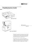
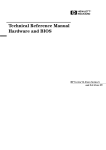
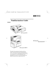
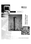
Familiarization Guide HP Vectra VL PC HP Vectra VL 5/xxx Series 5 PC HP Vectra VL MT PC Notice The information contained in this document is subject to change without notice. Hewlett-Packard makes no warranty of any kind with regard to this material, including, but not limited to, the implied warranties of merchantability and fitness for a particular purpose. Hewlett-Packard shall not be liable for errors contained herein or for incidental or consequential damages in connection with the furnishing, performance, or use of this material. Hewlett-Packard assumes no responsibility for the use or reliability of its software on equipment that is not furnished by Hewlett-Packard. This document contains proprietary information that is protected by copyright. All rights are reserved. No part of this document may be photocopied, reproduced, or translated to another language without the prior written consent of Hewlett-Packard Company. Centronics® is a registered trademark of Centronics Data Computer Corporation. Microsoft®, Windows® and MS-DOS® are registered trademarks of the Microsoft Corporation. Novell® and Netware® are registered trademarks of Novell Inc. PentiumTM is a trademark of the Intel Corporation. SoundBlasterTM is a trademark of Creative Technology Limited. Hewlett-Packard France Performance Desktop Computing Division 38053 Grenoble Cedex 9 France 1997 Hewlett-Packard Company HP Vectra VL 5/xxx Series 5 PC This guide is for experienced technicians who have already completed the HP Vectra PC family training course. It is a self-paced training guide designed to train you to repair the PC. It solely contains information specific to the repair of these PCs. For information on the installation of accessories, see the User’s Guide and the Online documents that are supplied with the PC. 1 HP Vectra VL 5/xxx Series 5 PC Desktop package Desktop package Front logo does not show processor speed or series information Wty: WBK@ Sup: SAB@ Model VL 5/200 series 5 Prod: D4570A #ABU S/N: FR63412345 Product information appears on a label on the lower front recess or the right hand side panel Remote Power-On network connector Power connector USB 2 HP Vectra VL 5/xxx Series 5 PC Minitower package Minitower package USB connector Front logo does not show processor speed or series information. Instead this information appears on a label on the right hand side panel Wty: WBK@ Sup: SAB@ Model VL 5/200 series 5 Prod: D4578A #ABA S/N: FR63498765 Voltage selection Power connector 3 HP Vectra VL 5/xxx Series 5 PC Product Specific Operations Product Specific Operations The following sections cover the following subjects: • Procedure for flashing the System BIOS • Procedures for checking or changing the system configuration • Procedures for replacing and installing components and accessories • Layout of the system board and backplanes • Layout of the Matrox Millennium graphics controller board, audio controller board, and the Ethernet 10BT PCI board. Flashing the Latest Version of the System BIOS BIOS upgrades can be downloaded, on to flexible diskette, from the HP World Wide Web site. Following the instructions which you are given, you will obtain the flash utility programs, FLASH.BAT, AUTOEXEC.BAT and PHLASH.EXE programs, the BIOS file, HAxxxx.FUL, and a file called pfmha106.bin, on a bootable flexible diskette. Insert the flexible diskette into drive A. Re-boot the system. Enter the command of the form FLASH HAxxxx.FUL (where xxxx is replaced by the version number of the BIOS that you have downloaded). Access HP World Wide Web Site World-Wide Web URL http://www.hp.com/go/vectrasupport Only use the flash utility programs that are supplied with the BIOS file. Do not switch off the computer until the System BIOS update has been completed, otherwise irrecoverable damage to the ROM could be incurred. 4 HP Vectra VL 5/xxx Series 5 PC Checking or Changing the System Configuration Checking or Changing the System Configuration Viewing or changing the current settings Processor frequency Viewable on the summary screen Changeable using the system board switches (SW1-4,7 — see the table on the next page) Main memory size Viewable on the summary screen Cache memory size Viewable on the summary screen Video memory size Viewable on the summary screen CMOS configuration data Clearable using the system board switches (SW6 — see the table on the next page) Keyboard power-on Can be enabled/disabled using the system board switches (SW9 — see the table on the next page) and within the Setup program IRQ selection Viewable and changeable within the Setup program Mass storage and I/O devices Parameters viewable on the summary screen and within the BIOS Setup program Enabled/disabled within the Setup program Locked/unlocked within the Setup program or the Lock my HP Vectra PC menu in Windows 95 Control Panel Video plug and play Enabled/disabled within the Setup program and within the Display menu in the Windows 95 Control Panel Passwords Not viewable Clearable using the system board switches (SW5 — see the table on the next page) Changeable within the Setup program or the Lock my HP Vectra PC menu in the Windows 95 Control Panel Screen blanking Enabled/disabled within the Setup program Screen hiding Enabled/disabled within the Lock my HP Vectra PC menu in the Windows 95 Control Panel or the Display/Screen Saver menu in the Windows 95 Control Panel Power management System standby: Enabled/disabled within the Setup program System suspend: Enabled/disabled within the Power menu in the Windows 95 Control Panel Monitor standby / suspend: Enabled/disabled within the Display/Screen Saver menu in the Windows 95 Control Panel The Setup program is run by typing whilst the initial Vectra logo is being displayed on the screen, just after power-on or restarting the computer. The Summary screen is displayed by typing being displayed. whilst the Vectra logo is 5 HP Vectra VL 5/xxx Series 5 PC Precautions When Replacing the System Board Switch 1-4,7 Functions of the System Board Switches Processor frequency (see the information printed on the system board) 5 Password: Open = enabled (default) Closed = disabled / clear User and Administrator passwords 6 Prevents changes to the PC’s configuration (in CMOS) in the Setup program: Open = normal (default — you can change the configuration in the Setup program) Closed = clear CMOS (to reload the Setup program defaults and to prohibit changes to the Setup program) 8 Not used 9 10 Keyboard space-bar power-on: Open = disabled Closed = enabled (default) Product identification: Open = normal operation (default) Closed = clear the product identification field in the CMOS memory Precautions When Replacing the System Board After replacing the system board, flash the System ROM with the latest version of the System BIOS. Then reconfigure the PC using the Setup program. Do not remove the thermal interface material between the processor and the heat-sink. To do so would affect the cooling of the processor. This interface material may stick the processor and heat-sink together. Do not attempt to separate them. Manipulate them as a single unit. Do not reinstall the memory modules haphazardly. There are three memory banks, which can be filled in any order, each comprising a pair of sockets. Different banks can contain memory module pairs of different sizes or types. However, in each bank which is occupied, you must install a pair of identical modules. Always use the specific extraction tool (PLCC IC Extraction, part number 5041-2553) when removing the video memory upgrade chips. 6 HP Vectra VL 5/xxx Series 5 PC Precautions When Replacing the Power Supply Precautions When Replacing the Power Supply With the minitower package, always check the position of the voltage selection switch. Replacing the Processor Chip If any thermal interface material, such as aluminium foil or silicone, is supplied with the heat-sink or the processor chip, place it carefully on the top of the processor before installing the heat-sink. System Board The system board layout is shown on the next page. Most desktop and minitower models are supplied with an S3 Trio 64 V2 video controller integrated on the system board. Models that are supplied with a Matrox graphics controller on a PCI board do not have an integrated graphics controller. 7 HP Vectra VL 5/xxx Series 5 PC System Board 8 HP Vectra VL 5/xxx Series 5 PC Backplanes Backplanes VL5 Desktop (front view) VL5 Desktop (rear view) (network models only) VL5 Minitower (top view) 9 HP Vectra VL 5/xxx Series 5 PC Accessory Boards that are Supplied with the PC Accessory Boards that are Supplied with the PC Matrox MGA Millennium This PCI board is Plug-and-Play. It is supplied with the correct drivers, and Video Controller Board does not require specific configuration when installed in this PC. 2 MB memory chips Top and bottom halves of the upgrade socket. (For the installation of a video memory upgrade module or the Matrox MPEG module). Display connector Configuration switches. (Set to their bottom position for normal operation). Audio Controller Board Although this is an ISA board, it is Plug-and-Play. It is supplied with the correct drivers, and does not require specific configuration when installed in this PC. CD-Audio Front panel (used only on the XA) Line-In Microphone-In Line-Out Internal Speaker Speaker-Out Joystick 10 HP Vectra VL 5/xxx Series 5 PC Accessory Boards that are Supplied with the PC Enhanced Ethernet Network Board The Enhanced Ethernet Network board, depicted below, is a PCI board, and so does not require specific configuration when installed in the PC. RJ-45 UTP 10 BaseT network Remote start For the coax adapter board Hole to accept a coax BNC 11 HP Vectra VL 5/xxx Series 5 PC Complete the Questionnaire to Check Your Understanding Complete the Questionnaire to Check Your Understanding Draw a circle around each letter that corresponds with a correct answer. (There may be more than one correct answer to each question). 1 What do you need to do to obtain the latest System BIOS? a Order a BIOS diskette. b Connect to the World Wide Web URL, at http://www.hp.com/go/ vectra/support. c Connect to ftp-boi.external.hp.com, and type anonymous as the login name. d Dial +1(208).344-1691, and connect with a 2400 baud modem. 2 What would you do to fix an IRQ conflict? a Look at the jumper and switch settings on each accessory board. b Run the BIOS Setup program, and select the configuration menu. 3 What would you do to enable video plug and play? a Nothing, it enables itself automatically on power-on. b Run the BIOS Setup program, and select the configuration menu, and the video sub-menu. c Go to the Windows 95 Control panel, and select the Display/Screensaver menu. d Go to the Windows 95 Control panel, and select the Display/Setting/AdvancedProperties/Monitor menu. 4 What would you do to check the size of the installed cache memory? a Run the Setup program by typing b Look at the summary screen by typing after restarting the PC. after restarting the PC. c Go to the Windows 95 Control panel, and select the General tab on the System menu. 12 HP Vectra VL 5/xxx Series 5 PC Answers and Explanations Answers and Explanations 1 What do you need to do to obtain the latest System BIOS? b Connect to the World Wide Web URL, at http://www.hp.com/go/ vectra/support. The World Wide Web site is kept updated with the latest version. 2 What would you do to fix an IRQ conflict? a Look at the jumper and switch settings on each accessory board. b Run the BIOS Setup program, and select the configuration menu. 3 What would you do to enable video plug and play? b Run the BIOS Setup program, and select the configuration menu, and the video sub-menu. d Go to the Windows 95 Control panel, and select the Display/ Setting/AdvancedProperties/Monitor menu. Video plug-and-play is normally enabled, by default. However, if it has been disabled in the Setup program, it must be enabled from there, too. It might be necessary to switch the display off, and the back on. 4 What would you do to check the size of the installed cache memory? b Look at the summary screen by typing after restarting the PC. 13 50% Paper not bleached with chlorine. Manual Part Number D4550-90901 Printed in France - 02/97