1
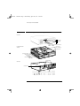
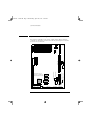
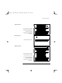
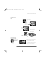
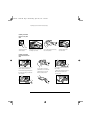
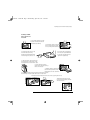
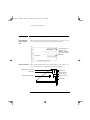
1book.bk : 1bookf.fb4 Page 1 Wednesday, April 30, 1997 3:36 PM Familiarization Guide HP Vectra VL PC HP Vectra VL 6/xxx Series 6 PC HP Vectra VL MT PC This guide is for experienced technicians who have already completed the HP Vectra PC family training course. It is a self-paced training guide designed to train you to repair the PC. It contains information specific only to the repair of these PCs. For information on the installation of accessories, see the User’s Guide and the Online documents that are supplied with the PC. 1book.bk : 1bookf.fb4 Page 2 Wednesday, April 30, 1997 3:36 PM Notice The information contained in this document is subject to change without notice. Hewlett-Packard makes no warranty of any kind with regard to this material, including, but not limited to, the implied warranties of merchantability and fitness for a particular purpose. Hewlett-Packard shall not be liable for errors contained herein or for incidental or consequential damages in connection with the furnishing, performance, or use of this material. Hewlett-Packard assumes no responsibility for the use or reliability of its software on equipment that is not furnished by Hewlett-Packard. This document contains proprietary information that is protected by copyright. All rights are reserved. No part of this document may be photocopied, reproduced, or translated to another language without the prior written consent of Hewlett-Packard Company. Centronics® is a registered trademark of Centronics Data Computer Corporation. Microsoft®, Windows® and MS-DOS® are registered trademarks of the Microsoft Corporation. PentiumTM is a trademark of the Intel Corporation. SoundBlasterTM is a trademark of Creative Technology Limited. Hewlett-Packard France Performance Desktop Computing Division 38053 Grenoble Cedex 9 France 1997 Hewlett-Packard Company 1book.bk : 1ch01.fb4 Page 1 Wednesday, April 30, 1997 3:36 PM Vectra Products Comparison Vectra Products Comparison Component HP Vectra VL 6/xxx PC HP Vectra VL 6/xxx MT PC Microprocessor Pentium II, 233 MHz or 266 MHz, 32 KB of level-1 cache memory, 256 KB or 512 KB of level-2 cache memory VRM 2.8 Volt Voltage Regulator Module Main memory 32 MB or 64 MB (standard), 192 MB(maximum), non-ECC EDO 60 ns DRAM, Six SIMM sockets (organized as three pairs) Graphics controller Cirrus 5446 integrated on the system board, with 2 MB video memory not upgradeable OR: Matrox MGA Millennium II on a PCI accessory board, with 4 MB video memory upgradeable to 12 MB Communications ports 2 USB connectors, 2 serial ports, parallel port, keyboard, mouse Mass storage 4.0 GB IDE or 2.5 GB IDE 4.0 GB IDE or 2.5 GB IDE 5 shelves (3 front access, 2 internal) 6 shelves (4 front access, 2 internal) Accessory board slots 5 slots 6 slots (2 PCI, 1 ISA, 2 combination PCI/ISA) (2 ISA, 2 PCI, 2 combination PCI/ISA) Audio board New ISA Plug-and-Play audio board on multimedia models CD-ROM drive 24✕ speed IDE on multimedia models Flexible disk drive New version without bezel Standard version with bezel Power supply Auto-ranging 100/240 VAC, 150 W input, 120 W output Manually switched 115/230 VAC, 200 W input, 160 W output Power saving 115 V, 60 Hz: 21 W in suspend mode, 27 W in standby mode 230 V, 50 Hz: 25 W in suspend mode, 30 W in standby mode 1 1book.bk : 1ch01.fb4 Page 2 Wednesday, April 30, 1997 3:36 PM New Package for the Desktop Models New Package for the Desktop Models Front view activity light status light (Multimedia models only) Front view with cover removed Hard disk drive 24✕ CD-ROM drive Flexible disk drive System board switches Video memory Processor VRM Main memory Retaining brackets Rear view Security lock hole Display Keyboard USB Mouse 2 Parallel Serial A Serial B 1book.bk : 1ch01.fb4 Page 3 Wednesday, April 30, 1997 3:36 PM Minitower Package Minitower Package Front view with cover removed System board switches Processor VRM Video memory Main memory Rear view Serial B Serial A Parallel Mouse USB Keyboard Voltage selection switch Display 3 1book.bk : 1ch01.fb4 Page 4 Wednesday, April 30, 1997 3:36 PM System Board and Backplanes System Board and Backplanes Most desktop and minitower models are supplied with a Matrox graphics controller on a PCI board, and do not have the integrated graphics controller loaded on the system board. 3.3 V Connector Power Connector Not Used VESA Connector 4 Kbd USB Mou Parallel Port Serial Port A Serial Port B External Battery Connector External Speaker System Board Switches Graphics Controller Chip External Start Video Memory (Items shown in grey are present only on models with integrated graphics controller) Internal Speaker Connector Processor Slot Hard Disk Connector CD-ROM Connector Flexible Disk Connector Memory Slots Display Voltage Regulator Module Status Panel A A B B C C 1book.bk : 1ch01.fb4 Page 5 Wednesday, April 30, 1997 3:36 PM System Board and Backplanes Desktop (front view) 2 ✕ PCI slot (shown in white) 2 ✕ ISA/PCI combination slot (shown in light grey) 1 ✕ system board slot (shown in dark grey) Desktop (rear view) 1 ✕ ISA slot (shown in grey) Minitower (top view) 2 ✕ PCI slot (shown in white) 2 ✕ ISA slot (shown in grey) 2 ✕ ISA/PCI combination slot (shown in light grey) 1 ✕ system board slot (shown in dark grey) 5 1book.bk : 1ch01.fb4 Page 6 Wednesday, April 30, 1997 3:36 PM Installing Accessories in the New Desktop Package Installing Accessories in the New Desktop Package The new package for the desktop models involves a number of new procedures. Removing the Cover 3. Unlock with the key 1. Press the latch down 2. Press the two tabs down, pivot the panel downward, and lift it off 4. Push the cover away from you and lift off Removing the Power Supply 1. Remove all external cables 2. Lift the front of the power supply to free the two side catches 3. Slide it horizontally out 6 4. Lift the power supply clear and lay it upside down on the front drive unit 1book.bk : 1ch01.fb4 Page 7 Wednesday, April 30, 1997 3:36 PM Installing Accessories in the New Desktop Package Installing an Accessory Board 1. Unscrew the retaining bracket 2. Remove the slot cover 3. Slide the board into the slot 4. Slide it horizontally out 5. Replace the retaining bracket. Installing an ISA board on the rear of the backplane 1. Unscrew the retaining bracket at the rear of the computer 2. Remove the rear tray by sliding it forward about 1.5 cm (1/2 inch), and lifting it up and out. Access is then clear for installing a short ISA board in the slot on the rear side of the backplane. 7 1book.bk : 1ch01.fb4 Page 8 Wednesday, April 30, 1997 3:36 PM Installing Accessories in the New Desktop Package Installing a Hard Disk Drive in the Top Rear Shelf 1. Unscrew the retaining bracket at the rear of the computer 2. Remove the rear tray by sliding it forward about 1.5 cm (1/2 inch), and lifting it up and out 3. Align the disk drive with the holes in the tray, and secure using the screws provided 4. Connect the data cable and power cable to the rear of the drive Installing a Hard Disk Drive in the Bottom Rear Shelf 1. Unclip the metal plate at the rear of the computer, and remove it 2. Remove the tray by pushing it from the inside, and sliding it out the back of the computer 8 3. Secure the 3.5-inch drive (shown above) or 5.25-inch drive (shown below) on to the tray with the screws provided 4. Slide the tray back into the rear of the computer 5. Replace the metal plate. Insert the flat end first then push it until it clicks into place. 1book.bk : 1ch01.fb4 Page 9 Wednesday, April 30, 1997 3:36 PM Installing Accessories in the New Desktop Package Installing a CD-ROM Drive or Zip Drive in a Front Shelf 1. Press the two retaining clips of the front drive unit inward, and slide the unit forward about half way 2. Push the two catches on the front drive unit down, and then slide the unit out, holding it with both hands 3. Carefully place the unit on its side, and remove the top mounting bracket. Remove the metal filler plate from the empty shelf, if there is one 4. If the drive has a tray, attach the drive on to the tray. (CD-ROM drives do not need a tray. Many zip drives require an HP-supplied tray) 5. Lower the drive into the free grove of the mounting bracket. Use the two pins on the mounting bracket to slot the drive into place. 6. Position the other mounting bracket on top, aligning it properly so that it clicks into place 7. Draw the computer’s cables through the front drive bay area and connect the data cable to the rear of each drive 8. Using both hands, lift the drive unit and slide it back into the computer about half way. Connect the power cable to the rear of each drive 9. Retrieve the universal front bezel from the PC’s chassis by opening the two clips. 10. Remove the filler bezel from the PC’s front panel and replace it with the universal front bezel. 9 1book.bk : 1ch01.fb4 Page 10 Wednesday, April 30, 1997 3:36 PM Installing Accessories in the New Desktop Package Replacing the Pentium II The Pentium II processor is contained on a module which is installed in a socket on the system board. It is held in place by a bracket. There are two Processor plastic clips, one on the top of each pillar of the bracket, to prevent the processor module from slipping out. Plastic clips Bracket pillars Heat-sink To remove the old processor module: 1 Press the two plastic clips towards each other. 2 Carefully pull the processor module away from its connector on the system board. The heat-sink is supplied with the processor, and is bolted to it by the manufacturer. 10 1book.bk : 1ch01.fb4 Page 11 Wednesday, April 30, 1997 3:36 PM Installing Accessories in the New Desktop Package Replacing the Flexible Disk Drive The flexible disk drive is mounted vertically in the front, right-hand edge of the computer. It is held in place by two plastic clips, one visible from above, and the other visible through a square hole in the right-hand bottom panel of the computer. Flexible disk drive Plastic clips To remove the flexible disk drive, press both plastic clips leftward, and pull the drive out through the front of the computer. To install the new processor module, reverse the above procedure. Replacing the System Board The system board is secured in place by the familiar system board handle mechanism. However, before the system board can be removed, it is necessary first to remove the left-hand bottom panel of the computer. This is held in place by a metal clip at the front end, and can be released by levering it at this end with a screw-driver, or similar implement. Once the replacement system board has been installed, reverse the above procedure. Insert the back end of the left-hand bottom panel into its slots in the back panel of the computer, and then push the front end until it clips into place. 11 1book.bk : 1ch01.fb4 Page 12 Wednesday, April 30, 1997 3:36 PM Accessories that are Supplied with the PC Accessories that are Supplied with the PC Matrox Millennium II Graphics Controller Board This PCI board is Plug-and-Play. It is supplied with the correct drivers, and does not require specific configuration when installed in this PC. 4 MB memory chips Top and bottom halves of the upgrade socket. (For the installation of a video memory upgrade module or the Matrox MPEG module). Display connector Audio Controller Board This new Plug-and-Play ISA board is supplied with the correct drivers, and does not require specific configuration when installed in this PC. Telephone answering device connector CD audio connector AUX-IN connector Multimedia control panel microphone connector Multimedia control panel connector Internal speaker connector Joystick connector 12 1book.bk : 1ch01.fb4 Page 13 Wednesday, April 30, 1997 3:36 PM Flashing the Latest Version of the System BIOS Flashing the Latest Version of the System BIOS BIOS upgrades can be downloaded, on to flexible diskette, from the HP World Wide Web site. Following the instructions which you are given, you will obtain the flash utility programs, FLASH.BAT, AUTOEXEC.BAT and PHLASH.EXE programs, the BIOS file, HD07xx.FUL, and a file called pfmhd106.bin, on a bootable flexible diskette. Insert the flexible diskette into drive A. Re-boot the system. Enter the command of the form FLASH HD07xx.FUL (where xx is replaced by the version number of the BIOS that you have downloaded). Access HP World Wide Web Site World-Wide Web URL http://www.hp.com/go/vectrasupport 13 1book.bk : 1ch01.fb4 Page 14 Wednesday, April 30, 1997 3:36 PM Complete the Questionnaire to Check Your Understanding Complete the Questionnaire to Check Your Understanding Draw a circle around each letter that corresponds with a correct answer. (There may be more than one correct answer to each question). 1 The following PC, supplied with a 4 GB hard disk, CD-ROM drive and audio board, has had components added by the user, and now no longer works. Which of the following could be the source of its failure to operate properly? a An 1 GB IDE hard disk drive has been fitted in the second internal shelf, and has been connected to the spare grey IDE connector. b A non-HP tape drive has been fitted in the lower front access shelf, and has been connected to the spare FDD connector. c There is an HP 32 MB memory module in memory socket C1, but socket C2 is empty. d Memory sockets B1 and B2 are empty. e There is a pair of non-HP 4 MB memory modules in bank A. f A non-HP network-board has been installed as a PCI accessory. 2 The client wishes to accelerate the processing throughput of the PC. Which of the following options are viable: a Replacing the current 233 MHz processor by a 266 MHz processor. b Replacing the current processor by an overdrive processor (when available). c Installing more level-2 cache memory modules. d Installing more main memory modules. 3 Which of the following statements is correct (when installing a device in the lower 5.25-inch front-access drive shelf of the desktop model)? a The new drive will already have the correct front bezel. b The filler bezel on the front panel needs to be modified with a knife. c The PC is supplied with the correct replacement bezel for the drive. d A kit of bezels (PN 5064-2667) needs to be ordered from HP. e No bezel is necessary. 14 1book.bk : 1ch01.fb4 Page 15 Wednesday, April 30, 1997 3:36 PM Complete the Questionnaire to Check Your Understanding 4 The client is unable to obtain the performance that is expected from a hard disk drive. What would you suggest might be the problem? a The drive has been installed in the slave position of the primary IDE cable. b The drive has been installed on the secondary IDE cable. c The jumpers on the drive have not been set correctly. d The drive has not been correctly detected by the Setup program, and needs to be configured manually. 5 The client is unable to start the PC from the keyboard. What would you suggest might be the problem? a The PC is not plugged in. b The Keyboard-Power-On function has not be enabled in the Setup program. c The Keyboard-Power-On function has not be enabled on the system board switches. d The Keyboard-Power-On function has not be enabled in Display Properties menu of the operating system. e The PC is running the wrong operating system for this function. 15 1book.bk : 1ch01.fb4 Page 16 Wednesday, April 30, 1997 3:36 PM Answers and Explanations Answers and Explanations 1 The following PC, supplied with a 4 GB hard disk, CD-ROM drive and audio board, has had components added by the user, and now no longer works. Which of the following could be the source of its failure to operate properly? c There is an HP 32 MB memory module in memory socket C1, but socket C2 is empty. d Memory sockets B1 and B2 are empty. e There is a pair of non-HP 4 MB memory modules in bank A. Installing non-HP accessory boards and drives does not infringe the specification of the PC (though the non-HP products are not supported by HP, and the customer pays for the visit, the HP PC remains supported). However, installing non-HP memory modules is not within the specification of the PC, and would cause the PC to be unsupported by HP. 2 The client wishes to accelerate the processing throughput of the PC. Which of the following options are viable: b Replacing the current processor by an overdrive processor (when available). d Installing more main memory modules. HP does not support the replacement of a processor by a faster one, unless it is an official overdrive equivalent for the original processor, even when models exist that use the faster processor. It is not possible to install modules into the processor module. Installing more main memory increases the performance of the virtual memory system. 3 Which of the following statements is correct (when installing a device in the lower 5.25-inch front-access drive shelf of the desktop model)? c The PC is supplied with the correct replacement bezel for the drive. The Universal Front Bezel is supplied in the side of the PC (see page 9) and should fit most designs of 5.25-inch drive. The kit of bezels can be ordered if the client has lost this bezel. The PC risks accumulating dust and dirt, and will not look attractive, if the drive is fitted without a bezel. 16 1book.bk : 1ch01.fb4 Page 17 Wednesday, April 30, 1997 3:36 PM Answers and Explanations 4 The client is unable to obtain the performance that is expected from a hard disk drive. What would you suggest might be the problem? a The drive has been installed in the slave position of the primary IDE cable. b The drive has been installed on the secondary IDE cable. c The jumpers on the drive have not been set correctly. d The drive has not been correctly detected by the Setup program, and needs to be configured manually. The correct answer to this question is, “all of the above”. Response (d) is unlikely to be the case, but is worth checking for the information that it can yield. 5 The client is unable to start the PC from the keyboard. What would you suggest might be the problem? a The PC is not plugged in. b The Keyboard-Power-On function has not be enabled in the Setup program. c The Keyboard-Power-On function has not be enabled on the system board switches. The function works with any operating system, and is not configured on any particular Windows menu. 17 1book.bk : 1bookb.fb4 Page xviii Wednesday, April 30, 1997 3:36 PM 50% Paper not bleached with chlorine. Manual Part Number D5040-90901 Printed in France - 05/97