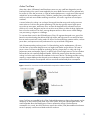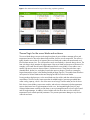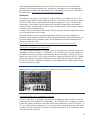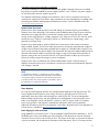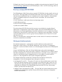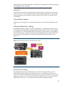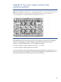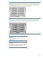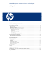
1
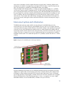
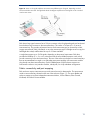
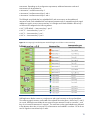
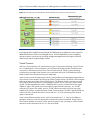
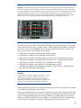
HP BladeSystem c3000 Enclosure technologies
technology brief
Abstract.............................................................................................................................................. 2
Overview of HP BladeSystem c3000 Enclosure ....................................................................................... 2
HP Thermal Logic technologies .............................................................................................................. 4
Active Cool fans .............................................................................................................................. 5
HP PARSEC architecture.................................................................................................................... 6
Thermal Logic for the server blade and enclosure ................................................................................. 7
Power supplies and enclosure power subsystem................................................................................... 8
HP BladeSystem Power Sizer ......................................................................................................... 9
Pooled power ............................................................................................................................ 10
Dynamic Power Saver mode ........................................................................................................ 11
Power Regulator ......................................................................................................................... 11
Power Capping for each server blade........................................................................................... 11
Interconnect options and infrastructure.................................................................................................. 12
Fabric connectivity and port mapping............................................................................................... 13
Virtual Connect .............................................................................................................................. 16
Enclosure-based DVD ROM................................................................................................................. 17
Onboard Administrator ...................................................................................................................... 17
Insight Display ............................................................................................................................... 19
Web GUI...................................................................................................................................... 20
Command-line interface .................................................................................................................. 20
Onboard Administrator cabling ....................................................................................................... 20
Enclosure link cabling ..................................................................................................................... 20
Recommendations.............................................................................................................................. 21
Summary .......................................................................................................................................... 21
Appendix A. Acronyms in text............................................................................................................. 22
Appendix B. Fan, power supply, and device bay population guidelines ................................................... 23
For more information.......................................................................................................................... 28
Call to action .................................................................................................................................... 28
Abstract
The HP BladeSystem c3000 Enclosure is the next generation in an evolution of the entire rackmounted infrastructure. The c3000 Enclosure is designed for remote sites, small and medium-sized
businesses, and data centers with special power and cooling constraints. This technology brief
provides an overview of the HP BladeSystem c3000 Enclosure, including a comparison with the
enterprise-class HP BladeSystem c7000 Enclosure, Thermal Logic power and cooling technologies,
and interconnect options.
This technology brief assumes the reader is familiar with HP ProLiant server technology and has some
knowledge of general BladeSystem architecture. For more information about the infrastructure
components, see the HP website at www.hp.com/go/bladesystem/.
Overview of HP BladeSystem c3000 Enclosure
The HP BladeSystem c3000 Enclosure, announced in September 2007, is the newest enclosure
implemented using the BladeSystem c-Class architecture. While the c7000 Enclosure is optimized for
enterprise data center applications, the c3000 Enclosure is optimized for other computing
environments, such as remote sites or small businesses. More information on c-Class architecture and
the c7000 Enclosure is available on the HP technology website at www.hp.com/servers/technology.
The c3000 Enclosure fits into standard size HP and third-party racks, and accommodates c-Class
form-factor server/storage blades and interconnect modules. It has the flexibility to scale from a single
enclosure holding up to 8 server blades, to a rack containing 7 enclosures holding up to 56
server/storage blades total. It is optimized for data centers with special power and cooling
constraints, such as DC powered racks, or data centers with low power and cooling capacities (under
4000 watts per rack). The c3000 Enclosure is designed for use with management devices such as
local KVM switches for local administration.
The HP BladeSystem c3000 Enclosure has a fully redundant design with redundant signal paths
between servers and interconnect modules. The enclosure is available with a single-phase power
subsystem. It can be populated with the following components:
• Up to 4 full-height (FH) server blades or up to 8 half-height (HH) server and/or storage blades per
enclosure
• Up to 4 interconnect modules simultaneously supporting a variety of network interconnect fabrics
such as Ethernet, Fibre Channel (FC), InfiniBand (IB), Internet Small Computer System Interface
(iSCSI), or Serial-attached SCSI (SAS)
• Active Cool fan kits for a maximum of 6 fans
• Up to 6 power supplies, accepting either low-line (100 to 120 volts alternating current [VAC]), or
high-line (200 to 240 VAC) power input
• Onboard Administrator (OA) management module
• Optional DVD drive
• Optional KVM enclosure module for connecting the c3000 to a in-rack KVM switch
Both c-Class enclosures have common critical components such as servers, interconnects, mezzanine
cards, storage blades, power supplies, and fans. Table 1 lists components supported by the c3000
and c7000 Enclosures.
2
Table 1. Comparison of components supported by HP BladeSystem c-Class Enclosures
Enclosure
c3000
c7000
Height
6U
10U
Blade orientation
Horizontal
Vertical
Blades supported
8 HH , 4 FH, 6HH/1FH
16 HH, 8 FH
Interconnect bays
4
8
Power supplies
6 at up to 1200 watts each
6 at 2250 watts each
Active Cool fans
6
10
Enclosure KVM support
Yes
No
CD/DVD support
Enclosure-based available
External
OA support
Single (now)
Single or dual
Dual (future)
Midplane speed
Tested up to 10 Gbit on Midplane
Tested up to 10 Gbit on midplane
OA Serial/USB connections
In front
In rear
Figures 1 and 2 show the front and rear view of the HP BladeSystem c3000 Enclosure.
Figure 1. HP BladeSystem c3000 Enclosure – front view
3
Figure 2. HP BladeSystem c3000 Enclosure – rear view
HP Thermal Logic technologies
HP BladeSystem c-Class products have been designed with a variety of HP Thermal Logic
technologies―a set of technologies integrated across server blades, enclosures, and interconnect
modules―all of which combined provide significant power and cooling benefits in comparison to
traditional rack and tower based servers. HP BladeSystem products reduce overall demand for power
and cooling by as much as 40 percent compared to standard rack and tower based servers. Thermal
Logic is the term that HP uses to define the mechanical design features, built-in intelligence, and
control capabilities throughout the BladeSystem c-Class. Thermal Logic technologies enable IT
administrators to make the most of the power and thermal environments. They provide an instant view
of power usage and temperature at the server, enclosure, or rack level. Thermal Logic technologies
automatically adjust power and thermal controls to minimize power and cooling usage while
maintaining adequate cooling for all devices and ensuring high availability.
HP Thermal Logic technologies include the following elements and capabilities:
• Active Cool fans
• Parallel Redundant Scalable Enclosure Cooling (PARSEC) design
• Instant power and thermal monitoring
• Pooled power for a variety of power redundancy modes
• Dynamic Power Saver mode
• Power Regulator
• Power workload balancing
4
Active Cool fans
Quite often, dense, full-featured, small form-factor servers use very small fans designed to provide
localized cooling in the specific areas needed by the server blade. Because such fans generate fairly
low airflow (in cubic feet per minute, or CFM) at medium backpressure, a single server often requires
multiple fans to ensure adequate cooling. Therefore, installing many server blades together in an
enclosure, with each server blade containing several fans, can result in significant cost and space
overhead.
A second solution for cooling is to use larger, blower-style fans that can provide cooling across an
entire enclosure. Such fans are good at generating CFM, but they typically require higher power
input, take up more space, make more noise, and must be designed for the maximum load in an
enclosure. As a result, designers may have to sacrifice server features to allow the large, high-power
fans to fit in the enclosure. Even then, ensuring adequate airflow to all the servers without leakage,
over provisioning, or bypass is a challenge.
To overcome these issues for the HP BladeSystem c-Class, HP engineers designed a new type of fan
based on aircraft technology that delivers both high airflow and high pressure in a small form factor
that can scale to meet future cooling needs. HP Active Cool fan technology optimizes airflow, reduces
power draw, and improves acoustic performance for any server blade configuration.
With 20 patents pending involving Active Cool fan technology and its implementation, HP Active
Cool fans are an innovative design that can cool eight server blades using as little as 100 watts of
power. Active Cool fans use ducted fan technology (the fan is longer than it is wide) with a high
performance motor and impeller (Figure 3) to deliver high CFM at a high pressure. The fan includes a
bell mouth inlet with a specially-designed impeller, followed by a stator section that also provides
cooling fins for the motor and acoustic treatments in the rear of the fan. This design providies cooling
capacity to support blade products beyond current roadmaps. Its unique shape allows for highpressure flow at even the slowest speeds with low noise levels and minimal power consumption.
Figure 3. Ducted fan cross-section and ducted fan blade compared to traditional server fan
Active Cool fans are controlled by the c-Class Onboard Administrator so that cooling capacity can be
ramped up or down based on the needs of the entire system. Along with optimizing the airflow, this
control algorithm allows the BladeSystem c-Class to optimize the acoustic levels and power
consumption. As a result, the c3000 Enclosure requires less airflow (CFM) than traditional rack-mount
servers to properly cool the server blades within the enclosure.
5
HP PARSEC architecture
HP Parallel Redundant Scalable Enclosure Cooling (PARSEC) architecture is a hybrid model for
cooling that combines the best of local and centralized cooling in a single system to ensure optimum
airflow and cooling for all servers. Density, once a barrier to cooling, is turned into an advantage
with HP Thermal Logic technologies like HP PARSEC architecture and HP Active Cool fans. With these
innovations, server blades get more cooling airflow where it is needed most and use less power than
traditional rack servers.
To optimize thermal design, HP developed a relatively airtight center air plenum, or air chamber. For
example, all device bays include a shutoff door that is normally closed to prevent air leakage through
that device bay. When a server blade is inserted, it seals into the center air plenum docking collar,
and the server shut-off door opens to allow airflow across that server blade. Similarly, the fan seals
into the center air plenum docking collar. Each fan bay includes louvers that automatically open when
a fan is installed. If a fan is not installed or is not functional, the pressure distribution around the fan
changes. This pressure change causes the louvers to close, ensuring that cooling air is not diverted
through the non-operating fan.
The enclosure and the components within it optimize the cooling capacity through unique mechanical
designs. Airflow through the enclosure is managed to ensure that every device gets cool air, that no
device sits in the hot exhaust air of another device, and that air only goes where it is needed for
cooling. Fresh air is pulled into the interconnect bays through a slot in the front of the enclosure. Ducts
move the air from the front to the rear of the enclosure, where it is then pulled into the interconnects
and the central plenum. The air is then exhausted out the rear of the system (Figure 4).
Figure 4. HP BladeSystem c3000 self-sealing enclosure
Base BladeSystem c3000 Enclosures ship with four installed fans that support up to four half-height
devices in device bays 1, 2, 5, and 6, or two full-height server blades in device bays 1 and 2.
Adding two additional fans to the enclosure allows population of eight half-height devices or four fullheight server blades.
In a four-fan configuration, the Onboard Administrator prevents server and storage blades installed in
device bays 3, 4, 7, and 8 from powering on until two additional fans are added into fan bays 1
and 3. To populate blade devices in all eight device bays, it is necessary to populate c3000
Enclosures with six Active Cool fans. Figure 5 shows enclosure fan bay and device bay population
guidelines. See Appendix B for more detailed fan and device bay population guidelines.
6
Figure 5. The c3000 Enclosure fan bay and device bay population guidelines
Thermal Logic for the server blade and enclosure
The server blade design uses precise ducting throughout the server blade to manage airflow and
temperature based on the unique thermal requirements of all the critical components. The airflow is
tightly ducted to ensure that no air bypasses the server blade and to obtain the most thermal work
from the least amount of air. This concept allows much more flexibility in heat sink design choice. The
heat sink design closely matches the requirements of the server blade and processor architecture. For
example, in the Intel® Xeon® based HP BladeSystem BL460c server blade, HP was able to use a
smaller, high-power processor heat sink than in rack-mount servers. These heat sinks have vapor
chamber bases, thinner fins, and tighter fin pitch than previous designs. This allows creating the
largest heat transfer surface in the smallest possible package (Figure 6). The smaller heat sink allows
more space for full-size DIMM sockets and hot plug hard drives on the server blades.
Ducting produces high pressure, so the server blade uses less airflow and that reduces fan power
requirements. The lower airflow requirement has the added benefit of optimizing available data
center cooling capacity, which is one of the main issues facing IT facilities today and in the future.
Each device (server blades, interconnect modules, and enclosure subsystems) includes temperature
sensors that monitor heat. If high temperature levels occur, the Integrated Lights-Outs (iLO) and
Onboard Administrator modules provide alerts to various management tools such as Insight Control
and HP Insight Manager. In addition, built-in failsafes will shut down devices in the enclosure if
temperature levels exceed specified parameters. This prevents permanent damage to any devices
within the enclosure.
7
Figure 6. Processor heat sink using fully ducted design (left) and a traditional heat sink in a 1U rack-mount server
(right)
Instant Thermal Monitoring provides a real-time view of heat, power, and cooling data. The Onboard
Administrator retrieves thermal information from all server blades, storage blades, and interconnect
modules in the enclosure to ensure an optimal balance between cooling, acoustic levels, and power
consumption. The Thermal Logic feature of the Onboard Administrator keeps fan and system power at
the lowest level possible. However, if the thermal load within the enclosure increases, the Thermal
Logic feature instructs the fan controllers to increase fan speeds to accommodate the additional
demand. Typically, a distributed element manager queries the thermal conditions of the hardware
every few minutes in a polling cycle. Onboard Administrator, on the other hand, monitors the thermal
conditions on the hardware in real-time, without a delay for a polling cycle.
HP’s Thermal Logic includes sophisticated algorithms in each BladeSystem ROM, iLO, and Onboard
Administrator. In combination, these algorithms minimize the power and cooling required to properly
operate the HP BladeSystem environment.
Power supplies and enclosure power subsystem
Power is delivered through a pooled power backplane that ensures that the full capacity of the power
supplies is available to all server blades. BladeSystem c3000 power supplies are single-phase power
supplies, supporting both low-line and high-line environments. Wattage output per power supply
depends on the rated alternating current (AC) input voltage. The BladeSystem c3000 Enclosure ships
with two power supplies; however, up to six power supplies can be installed, depending on the AC
redundancy level required and the number of devices installed in the enclosure. AC power supplies
auto-switch between 100VAC and 240VAC, to provide deployment options.
The BladeSystem c3000 Enclosure houses the power supplies in the same enclosure as the server
blades, storage blades, and interconnect modules (Figure 7). The power supply modules connect to a
passive power backplane that distributes power to all the components in a shared manner. Moving
the power supplies into the enclosure allowed HP to reduce the transmission distance for DC power
distribution and to use an industry-standard 12V infrastructure for the BladeSystem c-Class. Using a
12V infrastructure allowed HP to eliminate several power-related components and improve power
efficiency on the server blades and in the infrastructure. The control circuitry was stripped and put on
the management board and fans.
8
Figure 7. HP BladeSystem c3000 Enclosure supports up to six power supplies
The new, high efficiency HP c3000 power supplies provide greater than 90 percent efficiency in AC
to DC conversion. These power supplies use the ProLiant universal form factor so they can also be
used in other ProLiant servers. Each AC power supply ships with a standard power distribution unit
(PDU) power cord (C13 to C14 ). By purchasing proper wall outlet cords, users can connect the
power supplies to standard wall outlets.
NOTE
Wall outlet power cords should only be used with low-line
(100 to 120 VAC) power sources. If high-line (200 to 240
VAC) power outlets are required, safety regulations require the
use of a PDU or a UPS between the c3000 Enclosure power
supplies and wall outlets.
The enclosure can contain up to six 1200-watt self-cooled power supplies. A pair of PDUs is required
for AC line redundancy. A variety of PDUs can be chosen, as indicated in the c3000 QuickSpecs
available at this URL: http://h18004.www1.hp.com/products/quickspecs/12790_div/12790_div.html. The
HP BladeSystem Power Sizer should be used to size the PDU appropriately for the c3000 storage and
server configuration.
HP expects that in the markets targeted for the c3000 Enclosure (midmarket and remote sites), the
c3000 will be connected to an uninterruptible power supply (UPS) for power backup instead of to a
PDU. Use the HP BladeSystem Power Sizer to determine the UPS capacity requirement.
NOTE
The rack-mountable HP R5500 UPS (5000VA/4500 watts)
supports four power supplies in the power supply redundant
(N+1) power mode.
HP BladeSystem Power Sizer
The HP BladeSystem Power Sizer is a tool that assists facilities teams and IT staff in sizing their power
and cooling infrastructure to meet the needs of an HP BladeSystem solution. The BladeSystem Power
Sizer is based on actual component-level power measurements of a system stressed to maximum
capability. The sizer allows a customer to select the type and number of components within each
server blade and enclosure and to see the effect of changes on power consumption and heat
loading.
9
Values obtained from the BladeSystem Power Sizer tool are based on worst case loads and are
intended for facility planning purposes only. Actual power consumption will vary with application
type, application utilization, and ambient temperature. The BladeSystem Power Sizer is available at
the following URL: http://www.hp.com/go/bladesystem/powercalculator.
Pooled power
All the power in the enclosure is provided as a single pool that any server blade can access. This
provides maximum flexibility when configuring the power in the system so that customers can choose
what level of redundancy is required. Because this power design has no zones, it facilitates both
N+N and N+1 power modes, which future-proofs the enclosure for higher power requirements, if
needed. Therefore, looking forward at least five years, HP believes there is sufficient power capacity
to handle future power-hungry devices.
If needed, customers can constrain the maximum BTUs per enclosure and rack to enable the enclosure
to fit in an existing rack power envelope.
The c3000 Enclosure has three configurable redundancy modes: power supply redundant, AC
redundant, and no redundancy mode. The c3000 Onboard Administrator or the Insight Display can
be used to select the power redundancy mode. The HP BladeSystem Onboard Administrator User
Guide is available at this URL:
http://h20000.www2.hp.com/bc/docs/support/SupportManual/c00705292/c00705292.pdf.
Typical power configuration connecting to UPS
If N+1 power supply redundancy is configured (Figure 8), then total power is defined as total power
available less one power supply (3+1 configuration = up to 3600W). Up to six power supplies can
be installed, with one power supply always reserved to provide redundancy. Typically, four power
supplies are used for an N+1 power supply connection to a high-line (200-240 VAC) UPS. A smaller
UPS may be adequate, but the power calculator should be used to determine the VAC required for
the UPS. In the event of a single power supply failure, the redundant power supply will take over the
load of the failed power supply.
Figure 8. Redundant HP BladeSystem c3000 power supplies connected to an HP R5500 UPS
Connecting to PDUs with AC redundancy to each rack
If N+N AC redundancy is configured, then total power available is the amount from the A or B side
containing fewer power supplies (3+3 configuration = up to 3600W). In this configuration, N power
supplies are used to provide power and N are used to provide redundancy, where N can equal 1, 2,
or 3. Any number of power supplies from 1 to N can fail without causing the enclosure to fail. When
correctly wired with redundant AC line feeds, this will also ensure that an AC line feed failure will not
cause the enclosure to power off.
10
Connecting with no power redundancy configured
If no power redundancy is configured, the total power available is defined as the power available
from all power supplies installed (six power supplies installed = up to 7200W). Any power supply or
AC line failure may cause the system to power off.
The Onboard Administrator manages power allocation rules of various components and can limit
overall power capacity for the enclosure. More information on power management is available in the
technology brief entitled “Managing the HP BladeSystem c-Class,” which is available at this URL:
www.hp.com/servers/technology.
Dynamic Power Saver mode
Dynamic Power Saver mode provides power load shifting for maximum efficiency and reliability.
Dynamic Power Saver technology, first introduced with the BladeSystem p-Class1U power enclosure,
maximizes power supply efficiency to provide real customer power savings that result in capital
savings. Power supply efficiency is simply a measure of AC watts input in versus DC watts out: At 50
percent efficiency, 2000W in would equal 1000W out. The difference is wasted energy, which
generates unnecessary heat.
Dynamic Power Saver mode is active by default since it saves power in the majority of situations.
When enabled, Dynamic Power Saver mode saves power by running the required power supplies at
a higher rate of utilization and putting unneeded power supplies in a standby mode. Dynamic Power
Saver uses the fact that most power supplies will operate less efficiently when lightly loaded and more
efficiently when heavily loaded. A typical power supply running at 20 percent load could have an
efficiency rating as low as 60 percent. However, at 50 percent load it could be up to 90 percent
efficient, providing a significant savings in power consumption.
Dynamic Power Saver is enabled by the Onboard Administrator module. When this feature is
enabled, the total enclosure power consumption is monitored in real-time and automatically adjusted
with changes in demand.
NOTE
In redundant environments, a minimum of two power supplies
are always active, and the maximum load that can be reached
on any power supply is 50 percent. Once the 50 percent load
is reached, another two power supplies are activated to ensure
that redundancy is maintained at all times.
Power Regulator
HP’s ProLiant Power Regulator provides iLO-controlled speed stepping for Intel x86 processors. The
Power Regulator feature improves server energy efficiency by giving processors full power for
applications when they need it and reducing power when they do not. This power management
feature enables ProLiant servers with policy-based power management to control processor power
states. Power Regulator can be configured for continuous, static low power mode or for Dynamic
Power Savings mode in which power is automatically adjusted to match processor demand.
Additional information on the HP Power Regulator is provided in the paper titled “Power Regulator for
ProLiant servers,” available at www.hp.com/servers/power-regulator.
Power Capping for each server blade
Using updated iLO 2 firmware (version 1.30) and updated System ROM/BIOS (dated May 1, 2007),
HP BladeSystem c-Class server blades now have the ability to limit the amount of power consumed.
Customers can set a limit in watts or BTUs per hour. The purpose of this limit is to constrain the amount
of power consumed, which reduces the heat output into the data center. The iLO 2 firmware monitors
11
server power consumption, checks it against the power cap goal, and, if necessary, adjusts server
performance to maintain an average power consumption that is less than or equal to the power cap
goal. This functionality is available on all Intel-based ProLiant server blades.
Using the Insight Power Manager (IPM) v1.10 plug-in to Systems Insight Manager v5.1, customers
can set power caps on groups of supported servers. The IPM software statically allocates the group
power cap among the servers in the group. The group cap is allocated equitably among all servers in
the group based on a calculation using the idle and maximum measured power consumption of each
server. In addition, IPM can track and graph over time the actual power usage of groups of servers
and enclosures. This provides data center facilities managers with measured power consumption for
various time periods, reducing the need to install monitored PDUs to measure actual power usage in
data centers.
Interconnect options and infrastructure
The BladeSystem enclosures easily enable connecting the ports of embedded devices to the
interconnect bays. The c3000 Enclosure signal midplane (Figure 9) acts as a PCI Express (PCIe) bus
connecting interconnect ports on blade devices to interconnect modules. It has eight device bay signal
connectors (one for each half-height server blade and two for each full-height server blade) and four
interconnect module connectors (one for each interconnect bay). The device connections are in groups
of lanes. Each lane is a group of four pins (two sending traces and two receiving traces), resulting in
full-duplex communication. This combination provides a 1x (500Mb/s) transfer rate with 2x = 2 lanes
(1Gb/s).
Figure 9. Diagram of the HP BladeSystem c3000 signal midplane
By taking advantage of the similar four-wire differential transmit and receive mechanism, the signal
midplane can support either network-semantic protocols (for example, Ethernet, Fibre Channel, and
InfiniBand) or memory-semantic protocols (PCIe), using the same signal traces. Figure 10 illustrates
how the physical lanes can be logically “overlaid” onto sets of four traces. Interfaces such as Gigabit
Ethernet (1000-base-KX) or Fibre Channel need only a 1x lane, or a single set of 4 traces. Higher
bandwidth interfaces, such as InfiniBand DDR, will need to use up to four lanes.
12
Figure 10. Traces on the signal midplane can transmit many different types of signals, depending on which
interconnect fabrics are used. The right-hand side of the diagram represents how the signals can be “overlaid”
onto the same traces.
Each device bay signal connector has a 100-pin connector with 64 high-speed signal pins hard-wired
from the device bay connector to the interconnect bays. This results in 16 lanes (64 ÷ 4) to each
interconnect bay. This provides at least two lanes to each interconnect port for connectivity to LAN,
storage area network (SAN), InfiniBand, or any other interconnect type. Full-height servers occupy two
half-height device bays and therefore have up to 32 lanes available.
A single lane supports up to 10-Gb signals, depending on the protocol requirement. Each lane
provides the flexibility of 1x, 2x, or 4x connections from the server blade mezzanine cards, which
provide connectivity to the interconnect bays. The rear of the enclosure includes four interconnect bays
that can accommodate four single or two redundant interconnect modules. All interconnect modules
plug directly into these interconnect bays. Each HP BladeSystem c3000 Enclosure requires two
interconnect switches or two pass-thru modules, side-by-side, for a fully redundant configuration.
Fabric connectivity and port mapping
Each enclosure requires interconnects to provide network access for data transfer. The interconnects
reside in interconnect bays located on the rear of the enclosure (Figure 11). The server blades and
enclosure support up to three independent interconnect fabrics, such as Ethernet, Fibre Channel,
InfiniBand, and Virtual Connect modules.
13
Figure 11. HP BladeSystem c3000 interconnect bay numbering
For interconnect bay mapping purposes, it does not matter in which device bay a server blade is
installed. The mezzanine connectors always connect to the same interconnect bays. Because the
connections between the device bays and the interconnect bays are hard-wired through the signal
midplane, the server mezzanine cards must be matched to the appropriate type of interconnect
module. For example, a Fibre Channel mezzanine card must be placed in the mezzanine connector
that connects to an interconnect bay holding a Fibre Channel switch.
Embedded NICs and adapters installed in Mezzanine 1 are supported by single-wide interconnects in
interconnect bays 1 and 2 respectively. Mezzanine 2 and 3 can be supported by either single-wide
or double-wide interconnects such as InfiniBand or 10 Gb Ethernet devices in interconnect bays 3 and
4. To simplify the installation of the various mezzanine cards and interconnect modules, the Onboard
Administrator uses an electronic keying process to detect any mismatch between the mezzanine cards
and the interconnect modules.
An internal connection on the midplane between interconnect bays 1 and 2 and an additional
connection between interconnect bays 3 and 4 provide an internal link for use as a crosslink port
between interconnect bays 1 and 2 or interconnect bays 3 and 4. NIC teaming can be configured
between embedded NICs and Mezzanine 1 NICs using the internal crosslinks between the switches
through this internal connection.
Several port types are referenced in Figures 12 and 13:
• Examples of 1x ports are 1-Gb Ethernet (1-GbE) pass-thru modules and Fibre Channel interconnect
modules.
• An example of a 2x port is a SAS interconnect module.
• Examples of 4x ports are 10-GbE pass-thru modules and InfiniBand interconnect modules.
A full-height server blade plugs into two device bay connectors and has 32 lanes available to the 4
interconnect bays (16 lanes x 2x in Figure 12). Interconnect bay 1 is reserved for Ethernet
interconnects. It connects embedded Ethernet NICs to the internal facing ports on the Ethernet
14
interconnect. Depending on the configuration requirements, additional mezzanine cards and
interconnects can be populated in:
• Mezzanine 1 and Interconnect Bay 2
• Mezzanine 2 and Interconnect Bays 3 and 4
• Mezzanine 3 and Interconnect Bays 3 and 4
The full-height server blade has four embedded NICs and can accept up to three additional
mezzanine cards. Each embedded NIC and optional mezzanine port is mapped through the signal
midplane to specific ports on interconnect bays. A full-height server blade installed in device bay 1
would have NICs mapped in the following manner:
• NIC 1 (PXE default) — Interconnect bay 1 port 5
• NIC 2 — Interconnect bay 1 port 13
• NIC 3 — Interconnect bay 1 port 1
• NIC 4 — Interconnect bay 1 port 9
Figure 12. Port mapping for HP BladeSystem c3000 full-height server blades to interconnect bays
Half-height server blades connect to a single power and signal connector on the signal midplane.
The remaining signal connector is allocated to the adjacent device bay (that is, device bays 1 and 5).
As a result, half-height server blades do not support four-port mezzanine cards on connector 1, and
they do not contain a Mezzanine 3 connector. The extra lanes on the signal midplane are allocated
to the adjacent device bay. A four-port PCIe x8 mezzanine card installed in connector 2 PCIe x8 can
send x2 signals to interconnect bays 3 and 4.
15
Figure 13 lists the available configurations for half-height devices installed in device bay N (1–8).
Figure 13. Port mapping for HP BladeSystem c3000 half-height server blades to interconnect bays
Port mapping differs slightly between full-height and half-height server blades due to the support for
additional mezzanine cards on the full-height version. HP has simplified the process of mapping
mezzanine ports to switch ports by providing intelligent management tools through the Onboard
Administrator and HP Insight Manager software.
Virtual Connect
With the c-Class architecture, HP introduced a new type of interconnect technology: Virtual Connect.
As it is implemented in c-Class architecture, Virtual Connect technology provides virtualized server
connections to the Ethernet (LAN) or Fibre Channel (SAN) networks. Virtual Connect technology
virtualizes the server-edge so that networks can communicate with pools of HP BladeSystem server
blades instead of the conventional one-to-one relationship.
Virtual Connect consists of hardware (the Virtual Connect module) and a management agent that runs
on the Virtual Connect module. Like Ethernet and Fibre Channel switches, the Virtual Connect modules
slide into the interconnect bays of the c3000 Enclosure. The Ethernet module is necessary to install
Fibre Channel because the Virtual Connect Manager software runs on a processor on the Ethernet
module. The Ethernet module has sixteen 1-GbE downlinks to servers (connected across the signal
midplane), eight 1-GbE uplinks to the network (RJ-45 copper Ethernet connectors), two 10-GbE
connectors (for copper CX4 cables), and one 10-GbE internal inter-switch link (across the signal
midplane) for a failover connection between Virtual Connect modules. The Fibre Channel module has
sixteen 4-Gb Fibre Channel downlinks to servers and four 1/2/4-Gb auto-sensing Fibre Channel
uplinks to the network.
Virtual connect Ethernet modules can be used in interconnect bays 1, 2, 3 and 4 when Ethernet
mezzanine cards are used in the appropriate mezzanine slot on the server blade. Virtual Connect
Fibre Channel modules can only be used in interconnect bays 3 and 4 and require a Fibre Channel
mezzanine card in Mezzanine slot 2 or 3 in the server blade.
16
Full details about Virtual Connect technology are available in the technology brief entitled “HP Virtual
Connect technology implementation for the HP BladeSystem c-Class” on the HP technology website at
www.hp.com/servers/technology.
Enclosure-based DVD ROM
The HP BladeSystem c3000 Enclosure has an optional CD/DVD ROM drive that installs in the front of
the enclosure. The Insight Display and Onboard Administrator allow system administrators to connect
and disconnect the media device to one or multiple servers at a time. In addition, a browser-based
console is available through the iLO functionality of each server blade. The console enables
administrators to:
• Use HP SmartStart to install system software and operating systems
• Install additional software
• Perform critical OS updates and patches
• Update server platform ROMs
The enclosure-based CD/DVD offers local drive access to server blades by using the Onboard
Administrator or Insight Display. When media is loaded in the enclosure-based DVD ROM, local
administrators can use the Insight Display to attach the media device to one or multiple server blades
simultaneously. When the DVD Connect Status screen is displayed on the Insight Display, choosing to
connect the media device to a server or group of servers prompts the user to connect or to connect
and reboot the server.
When it is connected and no read operations have occurred in the last 16 seconds, the media device
can be disconnected from server blades.
Onboard Administrator
The Onboard Administrator is a management controller module that resides within the HP
BladeSystem c3000 Enclosure. The Onboard Administrator works with the iLO 2 management
processors on each server blade to form the core of the management architecture for HP BladeSystem
c-Class.
Unique to the BladeSystem c-Class, the Onboard Administrator is the enclosure management
processor, subsystem, and firmware base used to support the c7000 Enclosure, the c3000 Enclosure,
and all the managed devices contained within these enclosures. It provides a secure single point of
contact for users performing basic management tasks on server blades or switches within the
enclosure. It is fully integrated into all HP system management applications.
The Onboard Administrator module offers web-based and command line interface (CLI)
manageability. It drives all management features through two interfaces:
• Inter-Integrated Circuit (I2C) — Through an I2C master, the Onboard Administrator controls and
monitors all data and interrupts with every subsystem in the infrastructure and in each server. All
subsystems have electrically erasable programmable read-only memory (EEPROM) to store fieldreplaceable unit (FRU) data. The Onboard Administrator provides I2C to fans, power supply
modules, and interconnect and device bays.
• Intelligent Chassis Management Bus (ICMB) — Through ICMB, the Onboard Administrator shares
information (for example, power and rack location) with the other infrastructure management
modules at the rack level.
17
The Onboard Administrator aggregates up to eight iLO 2 ports in a c3000 Enclosure, simplifying
cable management and providing a graphical interface to launch individual server iLO management
interfaces.
The rear of each module has an LED (blue unit identification) that can be enabled locally or remotely
and can be used to identify the enclosure from the back of the rack.
The c3000 Enclosure currently supports one Onboard Administrator module. Enclosure devices
continue to operate normally in the event of a hardware failure or removal; however, management
capabilities of the enclosure are lost. Enclosure fans run at full speed to ensure adequate cooling
when no Onboard Administrator is present.
Onboard Administrator collects system parameters related to thermal and power status, system
configuration, and managed network configuration. It manages these variables cohesively and
intelligently so that IT personnel can configure the HP BladeSystem c-Class and manage it in a fraction
of the time that other solutions require.
Onboard Administrator retrieves thermal information from the components in the enclosure. If the
enclosure’s thermal load increases, the Onboard Administrator’s thermal logic feature instructs the fan
controllers to increase fan speeds to accommodate the additional demand. Individual fan speeds can
be adjusted to reduce noise and power consumption, and to compensate for airflow differences
within the enclosure. Performance of each subsystem is proactively monitored, and any failures or
warnings can be reported to the system log and to broader infrastructure management tools such as
HP Systems Insight Manager (when SNMP is enabled). The Onboard Administrator manages
subsystem failure by taking appropriate action, including adjusting fan speed or reducing power
consumption, to maintain the enclosure’s ability to operate.
The Onboard Administrator uses sophisticated power measurement sensors to accurately monitor
exactly how much power is being consumed and how much power is available. Because Onboard
Administrator uses real-time measured power data instead of maximum power envelopes, customers
can deploy as many servers and interconnect modules as possible for the available power.
Onboard Administrator includes logic to manage multiple enclosures in a rack. The Onboard
Administrator allows single-point access for up to four enclosures. Thus, an IT administrator can use a
single sign-on to log into a single Onboard Administrator and use the web GUI to graphically view
and manage all the c-Class components within the linked enclosures. For example, an IT administrator
could automatically propagate management commands—such as putting an upper limit on power
levels for all server blades—throughout the linked enclosures.
A major advantage of the HP BladeSystem c-Class is its configuration flexibility. The configuration
logic resides in the management controller module in the front of the enclosure. The Onboard
Administrator module communicates with the iLO 2 management processor on each server blade to
form the core of the management architecture for HP BladeSystem c-Class. The configuration logic
powers up the interconnect modules first. Server blades are not powered up until the Onboard
Administrator has verified that the configuration is correct. If there is a configuration issue, the Insight
Display identifies the issue and possible remedies.
To assist IT administrators in the configuration and setup process, the Onboard Administrator verifies
four attributes for each server blade and interconnect module as they are added to the enclosure:
• Electronic keying—The Onboard Administrator automatically queries all mezzanine cards and
interconnect modules as they are deployed to check whether the interconnect fabric types match. If
they do not, the Onboard Administrator issues a warning with suggested corrective action.
• Power—The Onboard Administrator ensures that sufficient power is available to power up a server
blade or interconnect module.
18
• Cooling—The Onboard Administrator makes sure there is sufficient cooling capacity for the server
blade or interconnect module by retrieving thermal information from all of the server blades, power
supplies, Active Cool fans, and interconnect modules in the enclosure.
• Location—The Onboard Administrator checks the locations of server blades, Active Cool fans, and
power supplies to determine if they are placed to receive proper cooling and to support the chosen
power configuration.
If a configuration problem exists, the Onboard Administrator gives diagnostic help so that the IT
technician can easily determine the problem by looking at the Insight Display.
The Onboard Administrator significantly enhances network infrastructure management by offering two
methods to initially configure the IP addresses of the server blade iLO 2 ports and the interconnect
module management ports through the management network: DHCP or Enclosure Bay Static IP
Addressing. This configuration capability is managed through a single point, the Onboard
Administrator, rather than managing each iLO or interconnect module individually.
There are three ways for IT technicians and administrators to access the Onboard Administrator:
• The Insight Display
• The web GUI
• A command-line interface (CLI)
More information about the Onboard Administrator is available in the technology brief entitled
“Managing the HP BladeSystem c-Class” at this URL:
http://h18004.www1.hp.com/products/servers/technology/whitepapers/proliant-servers.html.
Insight Display
The Insight Display (Figure 14) is an ever-ready, rack-mounted information exchange device with
access to all of the Onboard Administrator setup, management, and troubleshooting information. It
simplifies initial enclosure configuration. It also provides information about the health and operation
of the enclosure. The device is big enough to display ample information, yet can be tucked away
inside the enclosure when not in use.
Figure 14. Insight Display Main Menu and Enclosure Settings menu
When the enclosure is powered up for the first time, the Insight Display launches an installation
wizard to guide the user through the configuration process. To identify the enclosure being
configured, the enclosure UID LED and the background of the Insight Display are illuminated blue
when the enclosure is initially powered on. The Installation Wizard automatically turns on the
enclosure UID at the beginning of the installation and turns it off when the installation is complete.
After configuring the enclosure, the Insight Display verifies that there are no installation or
configuration errors.
19
More information about the Insight Display is available in the technology brief entitled “Managing the
HP BladeSystem c-Class” at this URL:
http://h18004.www1.hp.com/products/servers/technology/whitepapers/proliant-servers.html.
Web GUI
The web GUI uses event-driven, push technology. No screen refresh is necessary to view failures or
events. If an event occurs, it is pushed to the web GUI and updated immediately. The GUI provides
seamless integration with HP OpenView, Insight Control Data Center Edition, and Insight Control
Linux® Edition.
Command-line interface
Administrators who commonly use scripting commands can access the Onboard Administrator this
way.
Onboard Administrator cabling
The standard Onboard Administrator module is preinstalled in a front-loading tray that also houses
the HP BladeSystem Insight Display. The Onboard Administrator module contains a serial connector
for connection to a PC with a null-modem RS232 serial cable. A USB connector is also available for
future USB connectivity. A separate rear-loading Onboard Administrator link module contains RJ-45
ports for enclosure link-up/link-down connectivity and Onboard Administrator network access
(Figure 15).
Figure 15. HP BladeSystem c3000 Onboard Administrator module
Enclosure link cabling
The Onboard Administrator link module contains two enclosure link ports to allow any active
Onboard Administrator module to access linked enclosures. On a standalone enclosure or top
enclosure in a series of linked enclosures, the top enclosure link-up port functions as a service port for
temporary connection to a PC with a CAT5 patch cable. It provides quick access to any Onboard
Administrator module, iLO 2, or interconnect module with Ethernet management ability.
20
The enclosure link-down port connects to the enclosure link-up port on the enclosure below it. The
enclosure link-up port connects to the enclosure link-down port on the enclosure above it. Linking the
enclosures enables the rack technician to access all the enclosures through the open link-up/service
port. If more c-Class enclosures are added to the rack, they can be linked through the open enclosure
link-up port on the top enclosure or the link-down port on the bottom enclosure.
NOTE
The enclosure link ports are designed only to support c-Class
enclosures in the same rack. The enclosure link-down port on the
top enclosure is the service port. The enclosure link-down port
on the bottom linked enclosure is unused.
IMPORTANT
The HP BladeSystem c-Class enclosure link ports are not
compatible with the HP BladeSystem p-Class enclosure link
ports.
Recommendations
HP recommends the following for configuring BladeSystem c-Class enclosures:
• Use Virtual Connect or managed switches to reduce cabling and management overhead.
• Use the HP BladeSystem Power Sizer.
• For all server blades other than BL685c, the InfiniBand 4x DDR single-port mezzanine card will
work in Mezzanine 1, but it will work better in Mezzanine 2 or Mezzanine 3. For BL685c, the
InfiniBand 4x DDR single-port mezzanine card will work equally well in Mezzanine 1, Mezzanine
2, or Mezzanine 3 connectors.
• The HP BladeSystem c-Class Solution Overview might indicate to install the Onboard Administrator
into the rear of the enclosure. This information applies to only the HP BladeSystem c7000
Enclosure. Install the Onboard Administrator module into the front of the HP BladeSystem c3000
Enclosure.
Summary
The HP BladeSystem c3000 Enclosure is the next generation of a new modular computing architecture
that consolidates and simplifies infrastructure, reduces operational cost, and delivers IT services more
effectively. The c3000 Enclosure is designed for remote sites, small and medium-sized businesses, and
data centers with special power and cooling constraints. Thermal Logic technologies provide the
mechanical design features, built-in intelligence, and control capabilities throughout the BladeSystem
c-Class that enable IT administrators to make the most of the power and thermal environments. The
shared, high-speed midplane and pooled-power backplane in the enclosure accommodate new
bandwidths and new technologies. The Onboard Administrator supplies an intelligent infrastructure to
provide essential power and cooling information and help automate the management of the
infrastructure. The BladeSystem c3000 Enclosure provides all the power, cooling, and infrastructure to
support c-Class modular servers, interconnects, and storage components, today and throughout the
next several years.
21
Appendix A. Acronyms in text
The following acronyms are used in the text of this document.
Table A-1. Acronyms
Acronym
Acronym expansion
AC
Alternating current
BTU
British thermal unit
CFM
Cubic feet per minute
CLI
Command line interface
DC
Direct current
DDR
Double data rate
FC
Fibre Channel
IB
InfiniBand
iLO
Integrated Lights Out
iSCSI
Internet Small Computer System Interface
KVM
Keyboard, video, mouse
LAN
Local area network
LED
Light emitting diode
NIC
Network interface card
OA
Onboard Administrator
PARSEC
Parallel, redundant, scalable enclosure cooling
PCIe
PCI Express
PDU
Power distribution unit
PSU
Power supply unit
SAN
Storage area network
SAS
Serial attached SCSI
U
Unit of measurement for rack-mount equipment (1U is 1.75
inches or 4.44cm)
UID
Unit identification
UPS
Uninterruptible power supply
VA
Volt-ampere
W
Watt
22
Appendix B. Fan, power supply, and device bay
population guidelines
Figure B-1. HP BladeSystem c3000 Enclosure – Fan population guidelines. For correct operation, fans and server
blades must be installed in the correct fan bays. The Onboard Administrator will ensure that fans and
server/storage blades are correctly placed before allowing systems to power on.
Base BladeSystem c3000 Enclosures ship with four fans installed, supporting up to four half-height
devices or two full-height server blades. Adding two additional fans to the enclosure allows
population with eight half-height devices or four full-height server blades.
• Four-fan configuration requires population of fan bays 2, 4, 5, and 6.
• Six-fan configuration enables population of all fan bays.
In a four-fan configuration the Onboard Administrator prevents blade devices in device bays 3, 4, 7,
and 8 from powering on and identifies the fan subsystem as degraded. To populate blade devices in
these device bays, populate c3000 Enclosures with six Active Cool fans.
23
Figure B-2. HP BladeSystem c3000 Enclosure – Power supply population guidelines
Table B-1. Power supply placement
Number of power supplies
Power supply bays used
2
1 and 4
4
1, 2, 4, and 5
6
All power supply bays filled
Table B-2. Power supply redundancy options
Number of power supplies
Power supply bays used
1+1
1 and 4
2+1
1, 4, and 2
3+1
1, 4, 2, and 5
4+1
1, 4, 2, 5, and 3
5+1
Populate all power supply bays
Table B-3. AC redundancy options
Number of power supplies
Power supply bays used
1+1
1 and 4
2+2
1, 2, 4, and 5
3+3
Populate all power supply bays
24
Figure B-3. HP BladeSystem c3000 Enclosure – Full-height server blade device bay numbering. Full--height servers
should be populated from bottom to top when viewing from the front of the enclosure. With four fans, only the
bottom two device bays can be used; with six fans, all device bays can be used.
Figure B-4. HP BladeSystem c3000 Enclosure – Half-height server blade device bay numbering. Half--height
servers should be populated from the bottom of the enclosure, in the following order: Device bays 1, 5, 2, 6, 3,
7, 4, 8.
IMPORTANT
When looking at the rear of the enclosure, device bay
numbering is reversed.
CAUTION
To prevent improper cooling or thermal damage, do not operate
the server blade or the enclosure unless all device bays are
populated with either a component or a blank.
25
Figure B-5. The c3000 Enclosure is divided by sheet metal panels into 2 full-height zones. Each horizontal zone
is divided vertically by a removable shelf to make a maximum of 8 half-height device bays. These zones reflect
the PCIe bus mapping in the signal midplane and limit placement of the server blade/storage blade combination.
The signal midplane has a direct PCIe link connecting adjacent paired device bays. Important: The server
blade/storage blade relationship cannot extend horizontally beyond the vertical dividers between full height
device bays, nor can it span the removable bay shelf dividing the zone into half-height device bays
.
The enclosure comes preinstalled with removable full-height dividers between the top four device bays
and the bottom four device bays. In addition, there is a half-height divider available for use between
device bays 4 and 8 if the full-height divider is removed. Using these combinations of dividers, the
following combinations of server blades can be installed:
• 8 half-height server blades with both full-height dividers installed
• 4 full-height server blades with both full-height dividers removed
• 4 half-height server blades in the bottom half of the enclosure with 1 full-height divider installed
• 2 full-height server blades in the bottom half of the enclosure with 1 full-height divider removed
• 4 half-height server blades in the top half with 1 full-height divider installed
• 2 full-height server blades in the top half with 1 full-height divider removed
• 1 full-height server blade and 2 half-height server blades in the top half with 1 full-height divider
removed and the half-height divider installed
CAUTION
If a full-height server blade is installed in device bay 1/5 and
half-height server blades are installed in device bays 2 or 6,
removing the full-height server blade leaves server blades
installed in device bays 2 and 6 unsupported. This might cause
damage to the server blades and the enclosure connectors.
Removing the full-height divider in the bottom half of the enclosure allows only full-height server blades
to be installed in the bottom half of the enclosure.
Removing the full-height divider in the top half of the enclosure requires either installing only full-height
server blades in the top half of the enclosure or installing the half-height divider between device bays
4 and 8. Installing the half-height divider enables installation of two half-height devices (two server
blades, one companion blade and one server blade, or one blade blank and one companion blade
or server blade) in device bays 4 and 8 and 1 full-height server blade in device bay 3/7.
26
When installing a companion blade (HP StorageWorks SB40c Storage Blade, HP PCI Expansion
Blade, or HP StorageWorks Ultrium 448c Tape Blade), the companion blade can be installed in
either of the paired device bays (1/2, 3/4, 5/6, or 7/8) with a half-height server blade installed in
the other paired device bay.
To install a companion blade with a full-height server blade, the companion blade must be installed in
device bay 8 with the full-height server blade installed in device bay 3/7. The half-height divider must
be installed between device bays 4 and 8, and either a blade blank or a half-height server blade can
be installed in device bay 4.
27
For more information
For additional information, refer to the resources listed below.
Resource description
Web address
General HP BladeSystem information
http://www.hp.com/go/bladesystem/
HP BladeSystem c-Class
documentation
http://h71028.www7.hp.com/enterprise/cache/316735-0-0-0121.html
HP BladeSystem c3000 Enclosure
Maintenance and Service Guide
http://h20000.www2.hp.com/bc/docs/support/SupportManual/
c01126895/c01126895.pdf
HP BladeSystem c3000 Enclosure
QuickSpecs
http://h18004.www1.hp.com/products/quickspecs/12790_div/1
2790_div.html
HP BladeSystem Onboard
Administrator User Guide
http://h20000.www2.hp.com/bc/docs/support/SupportManual/
c00705292/c00705292.pdf
HP BladeSystem c-Class interconnects
www.hp.com/go/bladesystem/interconnects
Technology briefs about HP
BladeSystem
http://h18004.www1.hp.com/products/servers/technology/white
papers/proliant-servers.html
HP BladeSystem Power Sizer
http://www.hp.com/go/bladesystem/powercalculator
HP BladeSystem c-Class firmware
compatibility matrix
http://www.hp.com/go/bladesystemupdates
Call to action
Send comments about this paper to [email protected].
© 2007 Hewlett-Packard Development Company, L.P. The information contained
herein is subject to change without notice. The only warranties for HP products and
services are set forth in the express warranty statements accompanying such
products and services. Nothing herein should be construed as constituting an
additional warranty. HP shall not be liable for technical or editorial errors or
omissions contained herein.
Intel and Xeon are trademarks or registered trademarks of Intel Corporation in the
U.S. and other countries and are used under license.
Linux is a U.S registered trademark of Linus Torvalds.
TC071001TB, October 2007