1
HP Integrity iLO 2 MP Operations Guide
HP Part Number: 5991-6005
Published: January 2008
© Copyright 2008, Hewlett-Packard Development Company, L.P.
Legal Notices
The information contained herein is subject to change without notice. The only warranties for HP products and services are set forth in the express
warranty statements accompanying such products and services. Nothing herein should be construed as constituting an additional warranty. HP
shall not be liable for technical or editorial errors or omissions contained herein.
Intel, Pentium, Intel Inside, Itanium, and the Intel Inside logo are trademarks or registered trademarks of Intel Corporation or its subsidiaries in
the United States and other countries.
Linux is a U.S. registered trademark of Linus Torvalds.
Microsoft and Windows are U.S. registered trademarks of Microsoft Corporation.
Acrobat is a trademark of Adobe Systems Incorporated.
Java is a US trademark of Sun Microsystems, Inc.
UNIX is a registered trademark of The Open Group.
Table of Contents
About This Document.......................................................................................................15
Intended Audience................................................................................................................................15
New and Changed Information in This Edition...................................................................................15
Publishing History................................................................................................................................15
Document Organization.......................................................................................................................16
Typographic Conventions.....................................................................................................................17
Related Information..............................................................................................................................17
Warranty Information...........................................................................................................................18
HP Encourages Your Comments..........................................................................................................18
1 Introduction to iLO 2 MP.............................................................................................19
Features.................................................................................................................................................19
Standard Features............................................................................................................................19
Always-on Capability.................................................................................................................20
Virtual Front Panel.....................................................................................................................20
Multiple Access Methods...........................................................................................................20
Security.......................................................................................................................................20
User Access Control...................................................................................................................20
Multiple Users............................................................................................................................20
IPMI over LAN...........................................................................................................................21
Firmware Upgrades...................................................................................................................21
Internal Subsystem Information................................................................................................21
DHCP and DNS Support...........................................................................................................21
HP SIM Group Actions..............................................................................................................21
SNMP.........................................................................................................................................22
SMASH.......................................................................................................................................22
SM CLP.......................................................................................................................................22
Mirrored Console.......................................................................................................................22
Remote Power Control...............................................................................................................22
Event Logging............................................................................................................................22
Advanced Features..........................................................................................................................22
Virtual Media.............................................................................................................................22
IRC..............................................................................................................................................22
Directory-Based Secure Authorization Using LDAP.................................................................22
LDAP Lite...................................................................................................................................23
Power Meter Readings...............................................................................................................23
HP Insight Power Manager........................................................................................................23
Advanced Pack License.........................................................................................................................23
Obtaining and Activating iLO 2 MP Advanced Pack Licensing.....................................................24
Supported Systems and Required Components and Cables................................................................24
iLO 2 MP Supported Browsers and Client Operating Systems............................................................24
Security.................................................................................................................................................25
Protecting SNMP Traffic..................................................................................................................26
Lights-Out Advanced/KVM Card........................................................................................................26
2 Ports and LEDs..............................................................................................................27
HP Integrity Server Blade Components...............................................................................................27
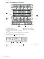
Onboard Administrator...................................................................................................................27
HP Integrity rx2660 Server Components..............................................................................................29
Table of Contents
3
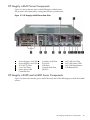
HP Integrity rx3600 and rx6600 Server Components...........................................................................29
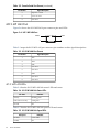
iLO 2 MP Status LEDs...........................................................................................................................30
iLO 2 MP Reset Button..........................................................................................................................31
Resetting Local User Accounts and Passwords to Default Values..................................................31
Console Serial Port and Auxiliary Serial Port.......................................................................................31
iLO 2 MP LAN Port...............................................................................................................................32
iLO 2 MP LAN LEDs.......................................................................................................................32
3 Setting Up and Connecting the Console...................................................................33
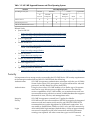
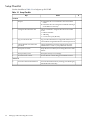
Setup Checklist......................................................................................................................................34
Setup Flowchart....................................................................................................................................35
Preparing to Set Up iLO 2 MP..............................................................................................................36
Determining the Physical iLO 2 MP Access Method......................................................................36
Determining the iLO 2 MP LAN Configuration Method................................................................36
Configuring the iLO 2 MP LAN Using DHCP and DNS.....................................................................37
Configuring the iLO 2 MP LAN Using ARP Ping................................................................................37
Configuring the iLO 2 MP LAN Using the Console Serial Port...........................................................39
Logging In to the iLO 2 MP..................................................................................................................40
Physically Connecting the Server Blade to the iLO 2 MP.....................................................................40
Connecting the Server Blade to the iLO 2 MP Using the Onboard Administrator.........................41
Auto-Login.................................................................................................................................41
Initiating an Auto-Login Session..........................................................................................42
Terminating an Auto-Login Session.....................................................................................43
User Account Cleanup during IPF Blade Initialization........................................................43
Auto-Login Troubleshooting................................................................................................43
Connecting the Server Blade to the iLO 2 MP Using the Console Serial Port.................................43
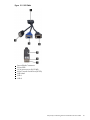
Connecting the SUV Cable to the Server Blade.........................................................................44
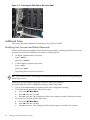
Additional Setup...................................................................................................................................46
Modifying User Accounts and Default Passwords.........................................................................46
Setting Up Security..........................................................................................................................47
Setting Security Access...............................................................................................................47
4 Accessing the Host Console........................................................................................49
Interacting with the iLO 2 MP Using the Web GUI..............................................................................49
Accessing Online Help....................................................................................................................50
Accessing the Host Console Using the TUI..........................................................................................50
Help System.....................................................................................................................................50
Accessing the Host Console Using vKVM (Integrated Remote Console)............................................51
Accessing the Host Console Using SMASH SM CLP...........................................................................51
Accessing iLO 2 MP Using Onboard Administrator............................................................................51
Accessing the Graphic Console Using VGA ........................................................................................51
5 Configuring DHCP, DNS, LDAP, and LDAP Lite........................................................53
Configuring DHCP...............................................................................................................................53
Configuring DNS..................................................................................................................................54
Configuring LDAP Extended Schema..................................................................................................55
Login Process Using Directory Services with Extended LDAP......................................................56
Configuring LDAP Lite Default Schema..............................................................................................56
Setting up Directory Security Groups.............................................................................................57
Login Process Using Directory Services Without Schema Extensions............................................58
6 Using iLO 2 MP............................................................................................................59
4
Table of Contents
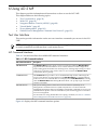
Text User Interface................................................................................................................................59
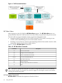
MP Command Interfaces.................................................................................................................59
MP Main Menu................................................................................................................................60
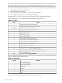
MP Main Menu Commands.......................................................................................................60
CO (Console): Leave the Main Menu and enter console mode.............................................61
VFP (Virtual Front Panel): Simulate the display panel.........................................................61
CM (Command Mode): Enter command mode.....................................................................61
SMCLP (Server Management Command Line Protocol): Switch to the SMASH SMCLP.....61
CL (Console Log): View the history of the console output...................................................61
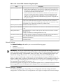
SL (Show Logs): View events in the log history...................................................................61
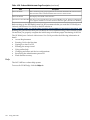
HE (Help): Display help for the menu or command in the MP Main Menu........................63
X (Exit): Exit the iLO 2 MP....................................................................................................63
Command Menu..............................................................................................................................63
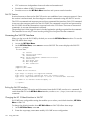
Command Line Interface Scripting.................................................................................................64
Expect Script Example................................................................................................................65
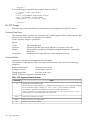
Command Menu Commands and Standard Command Line Scripting Syntax.............................66
BP: Reset BMC passwords..........................................................................................................67
BLADE: Display BLADE parameters.........................................................................................67
CA: Configure asynchronous local serial port............................................................................68
DATE: Display date.....................................................................................................................69
DC (Default Configuration): Reset all parameters to default configurations.............................69
DF: Display FRU information.....................................................................................................69
DI: Disconnect LAN, WEB, SSH or Console..............................................................................70
DNS: DNS settings......................................................................................................................70
FW: Upgrade the MP firmware...................................................................................................70
HE: Display help for menu or command in command menu interface.....................................70
ID: System information settings................................................................................................71
IT: Inactivity timeout settings...................................................................................................71
LC: LAN configuration usage.....................................................................................................72
LDAP: LDAP directory settings..................................................................................................72
LDAP: LDAP group administration......................................................................................74
LDAP: LDAP Lite...................................................................................................................74
LM: License management............................................................................................................74
LOC: Locator UID LED configuration........................................................................................74
LS: LAN status...........................................................................................................................74
PC: Power control access............................................................................................................75
PM: Power regulator mode.........................................................................................................75
PR: Power restore policy configuration......................................................................................76
PS: Power status.........................................................................................................................76
RB: Reset BMC............................................................................................................................76
RS: Reset system through the RST signal...................................................................................77
SA: Set access LAN/WEB/SSH/IPMI over LAN ports................................................................77
SNMP: Configure SNMP parameters..........................................................................................77
SO: Security option help.............................................................................................................78
SS: System Status.......................................................................................................................78
SYSREV: Firmware revisions......................................................................................................79
TC: System reset through INIT or TOC signal...........................................................................79
TE: Send a message to other mirroring terminals......................................................................79
UC: User Configuration (users, passwords, and so on).............................................................80
WHO: Display a list of iLO 2 MP connected users.......................................................................81
XD: iLO 2 MP Diagnostics or reset..............................................................................................81
Web GUI................................................................................................................................................82
System Status...................................................................................................................................82
Status Summary > General ........................................................................................................82
Table of Contents
5
Status Summary > Active Users.................................................................................................83
Server Status > General..............................................................................................................84
Server Status > Identification.....................................................................................................85
System Event Log.......................................................................................................................86
Events....................................................................................................................................87
Integrated Remote Console (vKVM)...............................................................................................88
IRC Requirements and Usage....................................................................................................88
Limitations of the vKVM Mouse and Keyboard..................................................................89
Browsers and Client Operating Systems that Support vKVM.............................................89
vKVM-Supported Resolutions and Browser Configurations...............................................89
Accessing the IRC.......................................................................................................................90
Integrated Remote Console Fullscreen.................................................................................92
Remote Serial Console.....................................................................................................................93
Virtual Serial Port.......................................................................................................................95
Virtual Media...................................................................................................................................95
Using iLO 2 MP Virtual Media Devices.....................................................................................96
Virtual CD/DVD....................................................................................................................97
Creating the iLO 2 MP Disk Image Files.............................................................................100
Virtual Floppy/USB Key......................................................................................................101
Virtual Media Applet Timeout...........................................................................................102
Supported Operating Systems and USB Support for vMedia.................................................102
Java Plug-in Version.................................................................................................................103
Client Operating System and Browser Support for vMedia....................................................103
Power Management.......................................................................................................................103
Power & Reset...........................................................................................................................103
Power Meter Readings.............................................................................................................105
Power Regulator.......................................................................................................................107
Administration...............................................................................................................................108
Firmware Upgrade...................................................................................................................109
Licensing...................................................................................................................................109
User Administration > Local Accounts....................................................................................111
Group Accounts.......................................................................................................................112
Access Settings..........................................................................................................................113
LAN..........................................................................................................................................113
Serial Page.................................................................................................................................114
Login Options Page..................................................................................................................115
Current LDAP Parameters.......................................................................................................116
Network Settings......................................................................................................................117
Network Settings > Standard...................................................................................................117
Domain Name Server...............................................................................................................118
SNMP Settings..........................................................................................................................119
BL c-Class.......................................................................................................................................121
Help...............................................................................................................................................122
SMASH Server Management Command Line Protocol.....................................................................123
SM CLP Features and Functionality Overview.............................................................................123
SM CLP Session........................................................................................................................124
Accessing the SM CLP Interface....................................................................................................124
Exiting the SM CLP Interface...................................................................................................124
Changing the iLO 2 Default Interface to SM CLP....................................................................124
Using the SM CLP Interface...........................................................................................................125
SM CLP Syntax..............................................................................................................................126
Command Line Terms..............................................................................................................126
Command Verbs.......................................................................................................................126
Command Targets....................................................................................................................127
Command Target Properties....................................................................................................127
6
Table of Contents
Command Options...................................................................................................................128
Level Option........................................................................................................................128
Display Option....................................................................................................................128
Character Set, Delimiters, Special, and Reserved Characters..................................................129
System1 Target...............................................................................................................................130
Target: SYSTEM1......................................................................................................................130
System Reset Power Status and Power Control.............................................................................130
Resetting the System................................................................................................................130
Displaying Power Status..........................................................................................................131
Powering Off the System..........................................................................................................131
Powering On the System..........................................................................................................131
Map1 (iLO 2) Target.......................................................................................................................131
Target: map1.............................................................................................................................131
Map1 Example..........................................................................................................................132
Resetting the iLO 2 MP.............................................................................................................132
Text Console Services.....................................................................................................................132
Opening the MP Main Menu from SM CLP............................................................................132
Target: map1/textredirectsap1.............................................................................................132
Opening the System Console Interface from SM CLP.............................................................133
Target: system1/consoles1/textredirectsap1........................................................................133
Switching Between the System Console and the SM CLP.......................................................133
Starting a System Console Session......................................................................................134
Determining the Session Termination Character Sequence for the System Console.........134
Exiting the System Console Session and Returning to SM CLP.........................................134
Entering the MP Main Menu Interface From SM CLP.......................................................134
Exiting the MP Main Menu Session and Returning to SM CLP.........................................134
Firmware Revision Display and Upgrade.....................................................................................134
SM CLP Firmware Targets........................................................................................................134
Target: map1/swinstallsvc1.................................................................................................134
Target: map1/swinventory1................................................................................................135
Target: map1/swinventory1/swid#......................................................................................135
Displaying Firmware Revisions...............................................................................................135
Firmware Upgrade...................................................................................................................136
Remote Access Configuration.......................................................................................................136
Telnet SM CLP Targets.............................................................................................................136
Target: map1/telnetsvc1......................................................................................................137
Telnet Examples..................................................................................................................137
SSH...........................................................................................................................................137
Target: map1/sshsvc1................................................................................................................137
SSH Examples...........................................................................................................................138
Network Configuration.................................................................................................................138
SM CLP Network Targets, Properties, and Verbs....................................................................138
Target: map1/enetport1.......................................................................................................138
Target: map1/enetport1/lanendpt1.....................................................................................138
Target: map1/enetport1/lanendpt1/ipendpt1......................................................................139
Target: map1/dhcpendpt1...................................................................................................139
Target: map1/dnsendpt1.....................................................................................................140
Target: map1/enetport1/lanendpt1/ipendpt1/gateway1.....................................................140
Target: map1/dnsserver1, map1/dnsserver2, map1/dnsserver3.........................................140
Target: map1/settings1/dnssettings1...................................................................................141
SM CLP Network Command Examples...................................................................................141
vMedia......................................................................................................................................142
Target: map1/oemhp_vm1/cddr1........................................................................................142
SM CLP vMedia Use Cases.................................................................................................143
User Accounts Configuration........................................................................................................143
Table of Contents
7
Target: map1/group1................................................................................................................143
Target: map1/group1/account#.................................................................................................143
User Account Examples...........................................................................................................144
LDAP Configuration......................................................................................................................144
Target: map1/settings1/oemhp_ldapsettings1..........................................................................144
LDAP Configuration Examples................................................................................................145
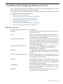
7 Installing and Configuring Directory Services .......................................................147
Directory Services...............................................................................................................................147
Features Supported by Directory Integration...............................................................................148
Directory Services Installation Prerequisites.................................................................................148
Installing Directory Services..........................................................................................................148
Schema Documentation.................................................................................................................149
Directory Services Support............................................................................................................149
eDirectory Installation Prerequisites.............................................................................................149
Required Schema Software............................................................................................................150
Schema Installer.............................................................................................................................150
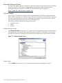
Schema Preview Screen............................................................................................................150
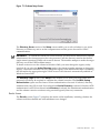
Setup Screen.............................................................................................................................150
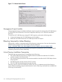
Results Screen...........................................................................................................................151
Management Snap-In Installer......................................................................................................152
Directory Services for Active Directory..............................................................................................152
Active Directory Installation Prerequisites....................................................................................152
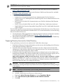
Preparing Directory Services for Active Directory........................................................................153
Installing and Initializing Snap-Ins for Active Directory..............................................................154
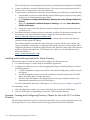
Example: Creating and Configuring Directory Objects for Use with iLO 2 in Active Directory...154
Directory Services Objects.............................................................................................................158
Active Directory Snap-Ins........................................................................................................158
Managing HP Devices In a Role.........................................................................................158
Managing Users In a Role...................................................................................................159
Setting Login Restrictions.........................................................................................................160
Setting Time Restrictions....................................................................................................160
Defining Client IP Address or DNS Name Access.............................................................161
Setting User or Group Role Rights................................................................................................162
Directory Services for eDirectory........................................................................................................163
Installing and Initializing Snap-In for eDirectory.........................................................................163
Example: Creating and Configuring Directory Objects for Use with iLO 2 MP Devices in
eDirectory......................................................................................................................................163
Creating Objects.......................................................................................................................163
Creating Roles..........................................................................................................................164
Directory Services Objects for eDirectory......................................................................................166
Adding Role Managed Devices................................................................................................166
Adding Members......................................................................................................................166
Setting Role Restrictions................................................................................................................167
Setting Time Restrictions...............................................................................................................168
Defining Client IP Address or DNS Name Access...................................................................168
Setting Lights-Out Management Device Rights............................................................................168
Installing Snap-Ins and Extending Schema for eDirectory on a Linux Platform..........................169
Installing the Java Runtime Environment................................................................................169
Installing Snap-Ins....................................................................................................................170
Extending Schema....................................................................................................................170
Verifying Snap-In Installation and Schema Extension.............................................................171
Using the LDAP Command to Configure Directory Settings in the iLO 2 MP.............................171
User Login Using Directory Services..................................................................................................172
8
Table of Contents
Certificate Services..............................................................................................................................173
Installing Certificate Services........................................................................................................173
Verifying Directory Services..........................................................................................................173
Configuring an Automatic Certificate Request.............................................................................173
Directory-Enabled Remote Management...........................................................................................173
Using Existing Groups...................................................................................................................174
Using Multiple Roles.....................................................................................................................174
Creating Roles that Follow Organizational Structure...................................................................175
Restricting Roles............................................................................................................................175
Role Time Restrictions..............................................................................................................175
IP Address Range Restrictions.................................................................................................176
IP Address and Subnet Mask Restrictions...............................................................................176
DNS-Based Restrictions............................................................................................................176
Role Address Restrictions........................................................................................................176
How Directory Login Restrictions Are Enforced..........................................................................176
How User Time Restrictions Are Enforced...................................................................................177
User Address Restrictions.............................................................................................................178
Creating Multiple Restrictions and Roles......................................................................................178
Directory Services Schema (LDAP)....................................................................................................179
HP Management Core LDAP Object Identifier Classes and Attributes........................................179
Core Classes..............................................................................................................................180
Core Attributes.........................................................................................................................180
Core Class Definitions..............................................................................................................180
hpqTarget............................................................................................................................180
hpqRole...............................................................................................................................181
hpqPolicy.............................................................................................................................181
Core Attribute Definitions........................................................................................................181
hpqPolicyDN.......................................................................................................................181
hpqRoleMembership...........................................................................................................181
hpqTargetMembership........................................................................................................182
hpqRoleIPRestrictionDefault..............................................................................................182
hpqRoleIPRestrictions.........................................................................................................182
hpqRoleTimeRestriction.....................................................................................................182
iLO 2 MP-Specific LDAP OID Classes and Attributes..................................................................183
iLO 2 MP Classes......................................................................................................................183
iLO 2 MP Attributes.................................................................................................................183
iLO 2 MP Class Definitions......................................................................................................183
hpqLOMv100......................................................................................................................183
iLO 2 MP Attribute Definitions................................................................................................184
hpqLOMRightLogin............................................................................................................184
hpqLOMRightRemoteConsole............................................................................................184
hpqLOMRightRemoteConsole............................................................................................184
hpqLOMRightServerReset..................................................................................................184
hpqLOMRightLocalUserAdmin.........................................................................................185
hpqLOMRightConfigureSettings........................................................................................185
Glossary.........................................................................................................................187
Index...............................................................................................................................195
Table of Contents
9
10
List of Figures
2-1
2-2
2-3
2-4
2-5
2-6
3-1
3-2
3-3
4-1
4-2
6-1
6-2
6-3
6-4
6-5
6-6
6-7
6-8
6-9
6-10
6-11
6-12
6-13
6-14
6-15
6-16
6-17
6-18
6-19
6-20
6-21
6-22
6-23
6-24
6-25
6-26
6-27
6-28
6-29
6-30
6-31
7-1
7-2
7-3
7-4
7-5
7-6
7-7
7-8
7-9
7-10
OA/iLO Network Port and Components......................................................................................28
Onboard Administrator LEDs and Buttons..................................................................................28
HP Integrity rx2660 Server Rear View..........................................................................................29
HP Integrity rx3600 and rx6600 Server Rear Ports and LEDs.......................................................30
Console Serial Port (RS-232) Connector........................................................................................31
iLO 2 MP LAN Port.......................................................................................................................32
Setup Flowchart.............................................................................................................................35
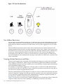
SUV Cable......................................................................................................................................45
Connecting the SUV Cable to the Server Blade.............................................................................46
Web Login Page.............................................................................................................................49
Status Summary Page....................................................................................................................50
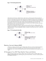
MP Command Interfaces...............................................................................................................60
Status Summary General Page......................................................................................................83
Status Summary Active Users Page..............................................................................................84
Server Status General Page............................................................................................................85
Server Status Identification Page...................................................................................................86
System Event Log Page.................................................................................................................87
Integrated Remote Console Page..................................................................................................91
Integrated Remote Console Window............................................................................................92
Remote Serial Console Page..........................................................................................................93
Remote Serial Console Window....................................................................................................94
Virtual Media Page........................................................................................................................96
Virtual Media Dialog Box (Before Connection)............................................................................98
Virtual Media Dialog Box (after connection)................................................................................99
Local Image File Dialog Box........................................................................................................100
Create Media Image Dialog Box..................................................................................................101
Virtual Floppy/USB Key..............................................................................................................102
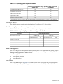
Power & Reset Page.....................................................................................................................104
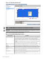
Power Meter Readings Page........................................................................................................106
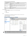
Power Regulator Page..................................................................................................................107
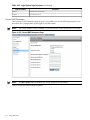
Licensing Page.............................................................................................................................110
Local Accounts Page....................................................................................................................111
Group Accounts Page..................................................................................................................112
LAN Page.....................................................................................................................................113
Serial Page....................................................................................................................................114
Login Options Page.....................................................................................................................115
Current LDAP Parameters Page..................................................................................................116
Standard Page..............................................................................................................................118
Domain Name Server Page..........................................................................................................119
SNMP Settings Page....................................................................................................................120
Onboard Administrator...............................................................................................................121
Help Page.....................................................................................................................................123
Schema Preview Screen...............................................................................................................150
Schema Setup Screen...................................................................................................................151
Schema Results Screen.................................................................................................................152
Directory Example.......................................................................................................................155
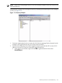
Create New HP Management Object Dialog Box........................................................................156
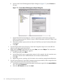
Select Users Dialog Box...............................................................................................................157
Lights-Out Management Tab.......................................................................................................157
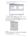
HP Devices Tab............................................................................................................................159
Members Tab...............................................................................................................................159
Role Restrictions Tab...................................................................................................................160
11
7-11
7-12
7-13
7-14
7-15
7-16
7-17
7-18
7-19
7-20
7-21
7-22
7-23
7-24
7-25
7-26
7-27
12
Logon Hours Screen....................................................................................................................161
New IP/Mask Dialog Box............................................................................................................161
Lights Out Management Tab.......................................................................................................162
Roles and Devices Example.........................................................................................................163
Select Object Subtype Dialog Box................................................................................................164
Setting Role Rights.......................................................................................................................165
Role Managed Devices Subtab....................................................................................................166
Members Tab (eDirectory)...........................................................................................................167
Role Restrictions Subtab (eDirectory)..........................................................................................167
Add New Restriction Dialog Box................................................................................................168
Lights-Out Management Device Rights Tab...............................................................................169
Admin User Gaining Admin Role Right, Example 1..................................................................175
Admin User Gaining Admin Role Right, Example 2..................................................................175
User and Role Access Restrictions...............................................................................................177
User Time Restrictions.................................................................................................................178
Restricting General Use...............................................................................................................179
Restricting the Reset Role............................................................................................................179
List of Figures
List of Tables
1
1-1
1-2
2-1
2-2
2-3
2-4
2-5
3-1
3-2
3-3
3-4
6-1
6-2
6-3
6-4
6-5
6-6
6-7
6-8
6-9
6-10
6-11
6-12
6-13
6-14
6-15
6-16
6-17
6-18
6-19
6-20
6-21
6-22
6-23
6-24
6-25
6-26
6-27
6-28
6-29
6-30
6-31
6-32
6-33
6-34
6-35
6-36
6-37
6-38
6-39
6-40
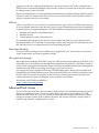
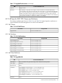
Publishing History Details............................................................................................................16
Supported Systems and Required Components Matrix...............................................................24
iLO 2 MP Supported Browsers and Client Operating Systems....................................................25
iLO 2 MP Status LEDs...................................................................................................................30
Console Serial Port Pinouts...........................................................................................................31
iLO 2 MP LAN Port Pinouts..........................................................................................................32
iLO 2 MP LAN Link Status LEDs..................................................................................................32
iLO 2 MP LAN Link Speed LEDs..................................................................................................32
Setup Checklist..............................................................................................................................34
Physical Connection Matrix..........................................................................................................36
LAN Configuration Methods........................................................................................................36
ARP Ping Commands....................................................................................................................38
MP Command Interfaces...............................................................................................................59
MP Main Menu Commands..........................................................................................................60
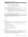
Events............................................................................................................................................62
Alert Levels....................................................................................................................................62
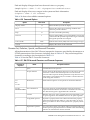
Command Menu Commands........................................................................................................63
Status Summary General Page Description..................................................................................83
Active Users Page Description......................................................................................................84
Server Status General Page Description........................................................................................85
Server Status Identification Page Description...............................................................................86
System Event Log Page Description..............................................................................................87
IRC Page Description.....................................................................................................................91
IRC Window Description..............................................................................................................92
Operating System Support for vMedia.......................................................................................103
Client Operating System and Browser Support for vMedia.......................................................103
Power & Reset Page Description.................................................................................................104
Power Meter Readings Page Description....................................................................................106
Power Regulator Page Description..............................................................................................108
Licensing Page Description.........................................................................................................110
Local Accounts Page Description................................................................................................112
Group Accounts Page Description..............................................................................................113
LAN Page Description.................................................................................................................114
Serial Page Description................................................................................................................115
Login Options Page Description..................................................................................................115
Current LDAP Parameters Page Description..............................................................................117
Standard Page Description..........................................................................................................118
DNS Page Description.................................................................................................................119
SNMP Settings Page Description.................................................................................................120
Onboard Administrator Page Description..................................................................................121
Supported Command Verbs........................................................................................................126
Command Options......................................................................................................................129
SM CLP Reserved Characters and Character Sequences............................................................129
system1 Properties.......................................................................................................................130
map1 Properties...........................................................................................................................131
/map1/textredirectsap1 Properties..............................................................................................133
/system1/consoles1/textredirectsap1 Properties..........................................................................133
swinstallsvc1 Properties..............................................................................................................134
swinventory1 Properties..............................................................................................................135
swid# Properties..........................................................................................................................135
telnetsvc1 Properties....................................................................................................................137
sshsvc1 Properties........................................................................................................................137
13
6-41
6-42
6-43
6-44
6-45
6-46
6-47
6-48
6-49
6-50
6-51
6-52
7-1
7-2
7-3
7-4
7-5
7-6
7-7
7-8
7-9
7-10
7-11
7-12
7-13
7-14
7-15
7-16
7-17
7-18
7-19
7-20
7-21
7-22
14
enetport1 Properties....................................................................................................................138
lanedpt1 Properties......................................................................................................................138
ipendpt1 Properties.....................................................................................................................139
dhcpendpt1 Properties................................................................................................................139
dnsendpt1 Properties...................................................................................................................140
gateway1 Properties....................................................................................................................140
dnsserver1, dnsserver2, dnsserver3 Properties...........................................................................140
dnssettings1 Properties................................................................................................................141
cddr1 Properties..........................................................................................................................142
group1 Properties........................................................................................................................143
account# Properties.....................................................................................................................143
oemhp_ldapsettings1 Properties.................................................................................................145
Lights Out Management Rights..................................................................................................162
Management Device Rights.........................................................................................................169
Core Classes.................................................................................................................................180
Core Attributes............................................................................................................................180
hpqTarget.....................................................................................................................................180
hpqRole........................................................................................................................................181
hpqPolicy.....................................................................................................................................181
hpqPolicyDN...............................................................................................................................181
hpqRoleMembership...................................................................................................................181
hpqTargetMembership................................................................................................................182
hpqRoleIPRestrictionDefault.......................................................................................................182
hpqRoleIPRestrictions.................................................................................................................182
hpqRoleTimeRestriction..............................................................................................................182
iLO 2 MP Classes.........................................................................................................................183
iLO 2 MP Attributes....................................................................................................................183
hpqLOMv100...............................................................................................................................183
hpqLOMRightLogin....................................................................................................................184
hpqLOMRightRemoteConsole....................................................................................................184
hpqLOMRightRemoteConsole....................................................................................................184
hpqLOMRightServerReset...........................................................................................................184
hpqLOMRightLocalUserAdmin..................................................................................................185
hpqLOMRightConfigureSettings................................................................................................185
List of Tables
About This Document
This document provides information and instructions on how to use the HP Integrated Lights
Out 2 Management Processor (iLO 2 MP) for Integrity.
The document printing date and part number indicate the document’s current edition. The
printing date changes when a new edition is printed. Minor changes may be made at reprint
without changing the printing date. The document part number changes when extensive changes
are made.
Document updates may be issued between editions to correct errors or document product changes.
To ensure that you receive the updated or new editions, subscribe to the appropriate product
support service. See your HP sales representative for details.
The latest version of this document can be found on the HP website
at:http://www.docs.hp.com
Intended Audience
This document provides technical product and support information for authorized service
providers, system administrators, and HP support personnel.
New and Changed Information in This Edition
The following information available for BL870c, BL860c, rx2660, rx3600, and rx6600 servers was
added to this guide:
•
vMedia - virtual floppy/USB key capability, see “Virtual Floppy/USB Key” (page 101)
This document is also a reference for the following HP Integrity servers with Integrity iLO:
•
•
•
rx7640
rx8640
Superdome sx2000
Publishing History
The publishing history below identifies the edition dates of this manual. Updates are made to
this publication on an unscheduled, as needed, basis. The updates consist of a complete replacement
manual and pertinent online or CD documentation.
Intended Audience
15
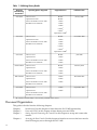
Table 1 Publishing History Details
Document
Manufacturing
Part Number
5991–6005
Operating Systems Supported
Supported Servers
Publication Date
HP-UX 11i v2
BL870c
January 2008
OpenVMS 8.3 1H1
BL860c
Microsoft Windows Server 2003
rx2660
Red Hat Linux and SuSE
rx3600
rx6600
rx76401
rx86401
Superdome sx20001
5991-5992
HP-UX 11i v2
BL860c
OpenVMS 8.3 1H1
rx2660
Microsoft Windows Server 2003
rx3600
Red Hat Linux and SuSE
rx6600
November 2007
rx76401
rx86401
Superdome sx20001
5991-5983
AD217-9001A
AB419-9006A
HP-UX 11i v2
BL860c
OpenVMS 8.3
rx2660
Microsoft Windows Server 2003
rx3600
Red Hat Linux and SuSE
rx6600
HP-UX 11i v2
BL860c
OpenVMS 8.3
rx2660
Microsoft Windows Server 2003
rx3600
Red Hat Linux and SuSE
rx6600
HP-UX 11i v2
rx2660
OpenVMS 8.3
rx3600
Microsoft Windows Server 2003
rx6600
June 2007
February 2007
December 2006
Red Hat Linux and SuSE
5971-4292
HP-UX 11i v2
rx3600
OpenVMS 8.3
rx6600
September 2006
Microsoft Windows Server 2003
Red Hat Linux and SuSE
1
All of the iLO 2 functionality is not currently available on this server.
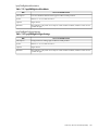
Document Organization
This guide is divided into the following chapters.
Chapter 1
Chapter 2
Chapter 3
Chapter 4
16
Introduction Use this chapter to learn about the iLO 2 MP functionality.
Ports and LEDs Use this chapter to learn about ports and LEDs.
Setting Up and Connecting the Console Use this chapter to set up and connect the
console.
Accessing the Host Console Use this chapter to learn how to access the host console
of an HP Integrity server through the iLO 2 MP.
Chapter 5
Chapter 6
Chapter 7
Glossary
Configuring DHCP, DNS, LDAP, and LDAP Lite Use this chapter to configure
DHCP, DNS, LDAP extended schema, and LDAP Lite default schema.
Using the iLO 2 MP This chapter provides information on the different interfaces
you can use to interact with the iLO 2 MP such as text user interface, web GUI,
and SMASH SM CLP.
Installing and Configuring Directory Services Use this chapter to learn about
installing and configuring directory services functions.
Use the glossary to learn iLO 2 MP terms and definitions.
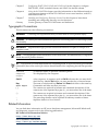
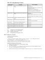
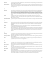
Typographic Conventions
This document uses the following conventions.
WARNING!
A warning lists requirements that you must meet to avoid personal injury.
CAUTION: A caution provides information required to avoid losing data or avoid losing system
functionality.
IMPORTANT: Important messages provide essential information to explain a concept or to
complete a task.
NOTE: A note highlights useful information such as restrictions, recommendations, or important
details about HP product features.
TIP: Tips provide you with helpful hints for completing a task. A tip is not used to give essential
information, but can be used to provide an alternate method for completing the task that precedes
it.
Command
Computer
Output
Ctrl+X
Key
User Input
[]
{}
...
|
A command name or qualified command phrase.
Text displayed by the computer.
A key sequence. A sequence such as Ctrl-X indicates that you must hold
down the key labeled Ctrl while you press another key or mouse button.
The name of a keyboard key. Return and Enter both refer to the same key.
Commands and other text that you enter.
The contents are optional in formats and command descriptions. If the
contents are a list separated by a pipe (|), you must select one of the items.
The contents are required in formats and command descriptions. If the
contents are a list separated by a pipe (|), you must select one of the items.
The preceding element can be repeated an arbitrary number of times.
Separates items in a list of choices.
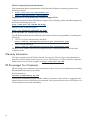
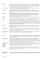
Related Information
You can find other information on HP server hardware management, Microsoft® Windows®,
and diagnostic support tools in the following publications.
HP Technical Documentation Website
http://www.docs.hp.com
Server Hardware Information
http://docs.hp.com/HP-UX/hw/
Typographic Conventions
17
Windows Operating System Information
Find information about administration of the Microsoft Windows operating system at the
following websites
•
•
http://www.docs.hp.com/windows_nt/
http://www.microsoft.com/technet/
Diagnostics and Event Monitoring: Hardware Support Tools
Complete information about HP hardware support tools, including online and offline diagnostics
and event monitoring tools, is at:
http://www.docs.hp.com/HP-UX/diag/
Website for HP Technical Support
http://us-support2.external.hp.com/
Books about HP-UX Published by Prentice Hall
The HP Books website lists the HP books that Prentice Hall currently publishes, including the
following:
•
•
HP-UX 11i System Administration Handbook
http://www.hp.com/hpbooks/prentice/ptr_0130600814.html
HP-UX Virtual Partitions
http://www.hp.com/hpbooks/prentice/ptr_0130352128.html
HP Books are available worldwide through bookstores, online booksellers, and office and
computer stores.
Warranty Information
The latest versions of the BCS Global Limited Warranty and Technical Support documentation is
posted on the HP website in the Enterprise Servers, Workstations, and System Hardware collection
under each server to which it applies, at: http://www.docs.hp.com.
HP Encourages Your Comments
HP encourages your comments concerning this document. We are truly committed to providing
documentation that meets your needs.
Send comments to:
[email protected]
Include title, manufacturing part number, and any comments, errors found, or suggestions for
improvement you have concerning this document. Also, please include what we did right so we
can incorporate it into other documents.
18
1 Introduction to iLO 2 MP
The Integrated Lights-Out Management Processor (iLO MP) for entry class Integrity servers is
an autonomous management subsystem embedded directly on the server. It is the foundation
of the server’s High Availability (HA) embedded server and fault management. It also provides
system administrators secure remote management capabilities regardless of server status or
location. The iLO MP is available whenever the system is connected to a power source, even if
the server main power switch is in the off position.
HP has used several different names to describe the management functionality embedded in
servers, including “the management processor.” In addition, HP uses the term “management
processor” to refer to any embedded microprocessor that manages a system. Management
processor is a descriptive term (such as “server”), and iLO is a brand name or label (such as
“Integrity”).
Remote access is the key to maximizing efficiency of administration and troubleshooting for
enterprise servers. Integrity servers are designed so all administrative functions that can be
performed locally, can also be performed remotely. iLO enables remote access to the operating
system console, control over the server’s power and hardware reset functionality, and works
with the server to enable remote network booting through a variety of methods.
iLO 2 is an Integrated Lights Out 2 Management Processor (iLO 2 MP) with the latest advanced
digital video redirection technology. This new feature gives you a higher performance graphics
console redirection experience than with the previous iLO.
This chapter addresses the following topics:
•
•
•
•
•
“Features” (page 19)
“Advanced Pack License” (page 23)
“Supported Systems and Required Components and Cables” (page 24)
“iLO 2 MP Supported Browsers and Client Operating Systems” (page 24)
“Security” (page 25)
Features
iLO 2 MP functionality includes the following:
• Control of power, reset, and Transfer of Control (TOC) capabilities
• Console access
• Display and recording of system events
• Display of detailed information about the various internal subsystems and field replaceable
units (FRUs)
• A virtual front panel to monitor system status and see the state of front panel LEDs
The iLO 2 MP is completely independent of the host system and the operating system. It has its
own microprocessor and runs its own firmware. The operating system cannot send packets out
on the iLO 2 MP LAN, and packets on the iLO 2 MP LAN cannot go to the operating system.
The iLO 2 MP LAN is exclusive to the iLO 2 MP and is driven by an embedded realtime operating
system (RTOS) running on the iLO 2 MP.
The iLO 2 MP offers the following standard and advanced features.
Standard Features
The iLO 2 MP standard features provide the following basic system board management functions,
diagnostics, and essential Lights-Out functionality on iLO 2-supported HP servers:
Features
19
Always-on Capability
The iLO 2 MP is active and available through the iLO 2 MP LAN connection and the local serial
port connection as long as the power cord is plugged in. In the event of a complete power failure,
the iLO 2 MP data is protected by an onboard battery backup.
Virtual Front Panel
The virtual front panel (VFP) presents a summary of the system front panel using direct console
addressing.
Multiple Access Methods
The available methods to access the iLO 2 MP are as follows:
IPMI/LAN
LAN
Local Serial Port
Web
Through the iLO 2 MP MAC address
Using telnet, web, or SSH to access the iLO 2 MP LAN
Using a terminal or laptop computer for direct connection
Using a GUI
Security
The iLO 2 MP provides strong security for remote management in IT environments, such as the
following:
•
•
•
•
User-defined TCP/IP ports
User accounts and access management
Lightweight Directory Access Protocol- (LDAP) based directory services authentication and
authorization
Encrypted communication using SSL and SSH
User Access Control
The iLO 2 MP is restricted by user accounts. User accounts are password protected and are
assigned access rights that define a specific level of access to the server and to the iLO 2 MP
commands. The iLO 2 MP supports both LDAP directory user authentication and locally stored
iLO 2 MP user accounts. iLO 2 MP users can have any of the following access rights:
Console Access
Power Control Access
Local User Administration Access
iLO 2 MP Configuration Access
Virtual Media Access
Right to access the system console (the host operating
system). This does not bypass host authentication
requirements, if any.
Right to power on, power off, or reset the server, and the
right to configure the power restore policy.
Right to configure locally stored user accounts.
Right to configure all iLO 2 MP settings and some system
settings, such as the power restore policy.
Enables Advanced Pack license users the right to use the
virtual media applet.
Multiple Users
Multiple users can interact with the iLO 2 MP. However, iLO 2 MP command mode and console
mode are mirrored, allowing only one user at a time to have write access to the shared console.
When a command is completed, write access is released and any user can initiate another
command.
20
Introduction to iLO 2 MP
IMPORTANT: Although the iLO 2 MP can support multiple simultaneous connections, to do
so can impact performance. HP does not recommend running more than eight simultaneous
connections.
The iLO 2 MP supports the following connections simultaneously:
•
•
•
•
•
•
•
Four web (each web connection can have a remote serial console connection as well and not
be counted as part of the total number of connections allowed)
Eight SSH
One local console serial port (RS-232)
Four IPMI over LAN
Four telnet
One Integrated Remote Console (IRC)
One vMedia
IPMI over LAN
The Intelligent Platform Management Interface (IPMI) option provides direct access from the
iLO 2 MP LAN port to the server Baseboard Management Controller (BMC) monitoring and
controlling functions such as temperature, voltage, fans, and power supplies. IPMI defines a
common interface for platform management hardware. With IPMI over LAN enabled, BMC
functions are available to other management software applications. The iLO 2 MP supports up
to four simultaneous IPMI over LAN connections.
Firmware Upgrades
Firmware upgrades enhance the functionality of the iLO 2 MP.
The MP firmware is packaged along with system, BMC, and FPGA/PSOC firmware. You can
download and upgrade the firmware package from the HP website at:
http://www.hp.com/go/bizsupport.
Internal Subsystem Information
The iLO 2 MP displays information about the following internal subsystems:
•
•
•
FRU information
System power state and fan status
Processor Status
DHCP and DNS Support
The iLO 2 MP supports the Dynamic Host Configuration Protocol (DHCP) and the Domain
Name System (DNS) configuration options for acquiring network information through the iLO
2 MP LAN port. When the iLO 2 MP starts, it acquires the port configuration stored on a DHCP
server to assign an IP address to the iLO 2 MP LAN port. If DNS is configured, this information
is updated on the DNS server. The simplest method to initially connect to the iLO 2 MP is with
the default DNS name found on the toe-tag on the server, for example, mp0014c29c064f.
HP SIM Group Actions
HP Systems Insight Manager (HP SIM) is a system-level management tool that supports executing
commands from HP SIM using the SSH interface. HP SIM enables you to perform similar
management activities across multiple iLO 2s (group actions) without requiring you to access
each iLO 2 MP individually. Group actions can be taken regardless of the server power state.
Fore more information about HP SIM, see:
http://www.hp.com/go/hpsim.
For the user guide, see the Information Library.
Features
21
SNMP
The SNMP is part of the TCP/IP protocol suit developed to manage servers on an IP network.
SNMP enables you to manage network performance, find and solve network problems, and plan
for network growth.
SMASH
Server Management Architecture for Server Hardware (SMASH) is an initiative by the Distributed
Management Task Force (DMTF) that encompasses specifications (Server Management CLP, SM
ME Addressing, SM Profiles) that address the interoperable manageability requirements of small
to large scale heterogeneous computer environments.
SM CLP
The SM CLP specification defines a user friendly command-line protocol that provides command
line interface (CLI) standards for interoperability.
Mirrored Console
The system console output stream is reflected to all connected console users, and any user can
provide input.
Remote Power Control
The iLO 2 MP enables remote power cycle, power on and power off, and TOC. It also provides
options to reset the system, the BMC, or iLO 2 MP.
Event Logging
The iLO 2 MP provides event logging, display, and keyword search of console history and system
events.
Advanced Features
The iLO 2 MP advanced features provide additional functionality such as the graphical integrated
remote console and virtual media. In addition, the advanced features increase security by
integrating iLO 2 MP user administration with the Active Directory or eDirectory.
The advanced features require the iLO 2 MP Advanced Pack license. See “Advanced Pack License”
(page 23).
NOTE: A HP ProLiant iLO 2 Advanced Pack license key will not work on an HP Integrity
server, and vice versa.
iLO 2 MP advanced features include the iLO 2 MP standard features and the following features:
Virtual Media
Virtual Media (vMedia) enables connection of client-based USB CD and DVD devices and disk
image files as virtual devices on the server, and requires the vMedia right and the Java plug-in
version 1.4.2_10 and above.
IRC
The IRC provides a remote console on Windows clients running the Internet Explorer browser
to HP Integrity-based Windows servers. It combines virtual keyboard, video, and mouse (vKVM).
Directory-Based Secure Authorization Using LDAP
The directory-based authentication and authorization option enables iLO 2 MP user accounts to
be defined in a centralized database on an LDAP server. iLO 2 MP users are authenticated when
22
Introduction to iLO 2 MP
logging in to the iLO 2 MP and authorization is given each time an iLO 2 MP command runs.
This provides a centralized database (LDAP server) of all user accounts and avoids the overhead
of creating users in each iLO 2 MP.
Directory authentication occurs by enabling Extended Schema or Default Schema. When Extended
Schema is used, the schema in the directory server must be extended. When Default Schema is
selected, schema extension is not needed.
LDAP Lite
LDAP Lite enables you to use directory authentication to log in to the iLO 2 MP without having
to do any schema extension on the directory server or snap-in installation on the client. In addition
to general directory integration benefits, iLO 2 MP schema-free integration provides the following:
•
•
•
Minimal maintenance and administration
Reliable security
Complements two-factor authentication
Not extending the schema on the directory server means the directory server does not know
anything about the iLO 2 MP object or privileges, and the only thing the iLO 2 MP queries from
the directory server is to authenticate the user name and password.
Power Meter Readings
The power meter readings feature enables you to graphically view and monitor server power
usage, temperature, and power regulator settings.
HP Insight Power Manager
HP Insight Power Manager (HP IPM), a plug-in to HP Systems Insight Manager (HP SIM), is an
integrated power monitoring and management application that provides centralized control of
server power consumption and thermal output. It extends the unified infrastructure management
framework of HP SIM by providing new energy levers into the server.
Leveraging HP power regulator technology, HP IPM makes policy-based power and thermal
management possible by enabling you to view and modify the power efficiency regulator mode
of the system. It expands the capacity of data centers by reducing the amount of power and
cooling required for supported Integrity servers and the server blades.
Information on HP IPM is available at:
http://www.hp.com/go/ipm
Advanced Pack License
The iLO 2 MP Advanced Pack license features sophisticated virtual administration and security
features for ultimate control of servers in data centers and remote sites. With an iLO 2 MP
Advanced Pack license key, you can activate powerful remote management features to install,
configure, monitor, update, and troubleshoot remote HP servers anywhere, anytime from a
standard web browser, command line or script.
Advanced Pack License
23
IMPORTANT: On HP Integrity server blades, the Advanced Pack license is standard. Remember
to save the Advanced Pack license key information that was provided by HP. If you ever need
to replace your server blade under warranty, you will need to transfer the key by typing the code
on the replacement server blade.
NOTE: A HP ProLiant iLO 2 Advanced Pack license key will not work on an HP Integrity
server, and vice versa.
Obtaining and Activating iLO 2 MP Advanced Pack Licensing
A free 30-day evaluation license is available for download on the HP website. The evaluation
license activates and accesses iLO 2 MP Advanced Pack features. You can only install one
evaluation license per iLO 2 MP. After the evaluation period, an iLO 2 MP Advanced Pack license
is required to continue using the advanced features. The iLO 2 MP Advanced Pack license features
automatically deactivate when the evaluation license key expires.
Systems that do not have VGA support all other Advanced Pack license features.
For more information, see the HP website at:
http://h71028.www7.hp.com/enterprise/cache/279991-0-0-0-121.html
Follow the factory-install or manual install instructions located on the Integrated Lights-Out
Advanced Pack for HP Integrity Servers; Certificate of License to Use; License Installation Card to activate
your license.
Supported Systems and Required Components and Cables
Table 1-1 lists the systems on which the iLO 2 MP is supported and the components and cables
that are required to operate the iLO 2 MP.
Table 1-1 Supported Systems and Required Components Matrix
Supported
Systems
Required Cables1
Required Components
Front console serial port (RS-232)
SUV or DB-9 cable
Rear OA/iLO network port
LAN cable
BL860c
rx2660
iLO 2 MP hardware is integrated into the system LAN, serial, and VGA cables
board
rx3600,
rx6600
Core I/O board without VGA; factory installed
LAN and serial cables
Core I/O board with VGA (optional)
(This is only supported on Windows OS.)
LAN, serial, and VGA cables
rx7640,
rx8640,
Superdome
sx2000
See your server documentation.
1
Cables are not provided with the server.
iLO 2 MP Supported Browsers and Client Operating Systems
The iLO 2 MP has an independent microprocessor. This architecture ensures that the majority
of iLO 2 MP functionality is available regardless of the host operating system.
Table 1-2 lists the client operating systems and browsers that are supported on iLO 2 MP:
24
Introduction to iLO 2 MP
Table 1-2 iLO 2 MP Supported Browsers and Client Operating Systems
Browsers
Java Plug-in 1.5.0_08
Firefox 2.0.0.4
Client Operating System
HP-UX
Windows
Linux
OpenVMS
11i
23/11.31
WS 2003
Enterprise
XP
Red Hat
Enterprise
SuSE
X
X
X
X
X
X
X
Internet Explorer 6.0
HP Secure Web Browser 1.7.13
8.3
X
Related Links
•
Java for HP-UX
— http://www.hp.com/products1/unix/java/versions/index.html
— http://www.hp.com/products1/unix/java/archives/index.html
•
Java for OpenVMS
— http://h18012.www1.hp.com/java/alpha
•
Firefox for HP-UX
— http://www.hp.com/products1/unix/java/firefox/index.html
Note: 1.5.0.00 needs patch
—
http://www.hp.com/go/firefox
•
Firefox for Linux
— http://linuxcoe.corp.hp.com
•
Firefox for Windows and Linux
— http://www.mozilla.com/firefox
•
Browser Support 1.5.0
— http://java.sun.com/j2se/1.5.0/system-configurations.html
•
Operating Systems for Montvale
— http://psweb1.cup.hp.com/~projects/sisl_prgm_mgmt/mvx%20(Low-end%20Montvale)/mvx%20info.htm
Security
It is important to have strong security surrounding the iLO 2 MP device. HP security requirements
of the enterprise and architected the iLO 2 MP include the following:
Authentication
iLO 2 MP incorporates authentication techniques with the use of 128-bit
Secure Socket Layer (SSL) encryption. It is password based for web and
password- and key-based for secure shell (SSH).
Authorization
Using local accounts, iLO 2 MP enables you to define up to 19 separate
users and to vary the server access rights of each user. The directory
services capabilities of iLO 2 MP enables you to maintain network user
accounts and security policies in a central, scalable database that supports
thousands of users, devices, and management roles.
Integrity
iLO 2 MP incorporates a trusted Java™ applet for vMedia.
Privacy
iLO 2 MP uses SSL for web connections, RSL-RC4 encryption for integrated
remote console and remote serial console, and SSH-DES3/DES128 2.0
recommended encryption algorithms for SSH-based connections. You
can enable or disable telnet, IPMI over LAN, web, and SSH connectivity.
Login
After initial failed login attempts (default three), a delay of approximately
one second is imposed on the serial connection and the login banner
warnings are repeated. All other connection types are disconnected.
Security
25
Because iLO 2 MP devices are completely autonomous and can be used to control the server,
treat them the same as other servers. For example, include the iLO 2 MP devices in the security
and network audits.
IMPORTANT: Ensure that physical access to the server is limited. Anyone can clear passwords
by pressing the power button for longer than four seconds.
Protecting SNMP Traffic
Because SNMP uses passwords, known as community strings, that are sent across the network
in clear text, you must enhance the network security when using SNMP traffic. To enhance
network security, do the following:
•
•
Reset the community strings (read only) with the same frequency and according to the same
guidelines as the administrative passwords. For example, select alphanumeric strings with
at least one uppercase letter, one numeral, and one symbol.
Set firewalls or routers to accept only specific source and destination addresses. For example,
you can allow inbound SNMP traffic into the host server only if it comes from one of the
predetermined management workstations.
TIP: Telnet sends data without encryption and is not a secure connection. HP recommends
using SSH instead of telnet because SSH uses encryption.
To enable and disable telnet access, use the SA command.
Lights-Out Advanced/KVM Card
The Lights-Out Advanced/KVM card (LOA) is a PCI-X card that you install into any sx2000-based
mid-range or high-end HP Integrity server.
The LOA card enables the Lights-Out Advanced vKVM and vMedia features of the iLO 2 MP
for the rx7640, rx8640, and Superdome sx2000 servers.
The LOA card is also a KVM card that offers physical video functionality for servers running
Windows, and USB functionality for servers running HP-UX, Windows, and OpenVMS.
All Lights-Out Advanced features are fully enabled on the LOA card--there is no additional
advanced pack license to purchase. At present, vKVM is only available for servers running
Windows and vMedia is available for servers running HP-UX, Windows, and OpenVMS.
The LOA card is not currently supported under Linux.
The Lights-Out Advanced features are accessed through the iLO 2 web interface.
26
Introduction to iLO 2 MP
2 Ports and LEDs
All iLO 2 MP functions are available through the server iLO 2 MP LAN port and the local and
remote serial ports. On HP Integrity server blades, all iLO 2 MP functions are available on the
Onboard Administrator. This chapter describes the available iLO 2 MP ports, connectors, and
LEDs on the HP Integrity server blades, and the rx2660, rx3600, and rx6600 servers.
This chapter addresses the following topics:
•
•
•
•
•
“HP Integrity Server Blade Components” (page 27)
“HP Integrity rx2660 Server Components” (page 29)
“HP Integrity rx3600 and rx6600 Server Components” (page 29)
“iLO 2 MP Reset Button” (page 31)
“Console Serial Port and Auxiliary Serial Port” (page 31)
HP Integrity Server Blade Components
Onboard Administrator is the enclosure management processor, subsystem, and firmware base
used to support the HP Integrity server blades and all the managed devices contained within
the enclosure. Onboard Administrator provides a single point from which to perform basic
management tasks on server blades or switches within the enclosure. Using this hardwired
knowledge, Onboard Administrator performs initial configuration steps for the enclosure, enables
runtime management and configuration of the enclosure components, and informs you of
problems within the enclosure through e-mail, SNMP, or the Insight Display.
Before setting up the HP BladeSystem Onboard Administrator, HP recommends that you read
the HP BladeSystem Onboard Administrator User Guide on the HP website at:
http://h20000.www2.hp.com/bc/docs/support/SupportManual/c00705292/c00705292.pdf
Reading this guide ensures that you understand the HP BladeSystem Onboard Administrator
and that you properly complete the initial setup to facilitate its proper functioning.
You can find other Onboard Administrator docs on the HP website at:
HP BladeSystem c-Class Onboard Administrator
Onboard Administrator
Figure 2-1 shows the Onboard Administrator OA/iLO network port and components.
HP Integrity Server Blade Components
27
Figure 2-1 OA/iLO Network Port and Components
1
2
3
OA/iLO Network Port
Onboard Administrator Bay 1
Onboard Administrator Bay 2 (redundant
if used)
4
5
Enclosure Link-Up Port
Enclosure Link-Down Port
Figure 2-2 shows the Onboard Administrator LEDs and buttons.
Figure 2-2 Onboard Administrator LEDs and Buttons
1
2
3
28
Onboard Administrator UID LED
Enclosure UID LED
Onboard Administrator Active LED
Ports and LEDs
4
5
Onboard Administrator Health LED
Onboard Administrator Reset Button
HP Integrity rx2660 Server Components
Figure 2-3 shows the rear view of the HP Integrity rx2660 server.
The system LAN functionality is integrated into the system board.
Figure 2-3 HP Integrity rx2660 Server Rear View
1
2
3
4
5
Power Supply 1 and LED
Power Supply 2 and LED
PCI-x/PCI-e Slots
Core LAN Ports
Smart Array P400
Controller Slot
6
7
8
9
Auxiliary Serial Port
VGA Port
USB Ports
Console Serial Port
(RS-232)
10
11
12
13
iLO 2 MP LAN Port
iLO 2 MP Status LEDs
iLO 2 MP Reset Button
UID Button/LED
HP Integrity rx3600 and rx6600 Server Components
Figure 2-4 shows the controls, ports, and LEDs on the rear of the HP Integrity rx3600 and rx6600
servers.
HP Integrity rx2660 Server Components
29
NOTE:
This figure is oriented vertically to match the orientation of the core I/O board.
Figure 2-4 HP Integrity rx3600 and rx6600 Server Rear Ports and LEDs
1
2
iLO 2 MP Serial Console
Port (RS-232) (DB-9F to
DB-9F cable) Connected to
emulation terminal device
(PC, laptop, or ASCII
terminal)
General Use Serial Port
(Printers, etc.)
3
4
USB 2.0 Ports (any USB
device)
iLO 2 MP LAN Port (10/100
LAN)
5
VGA Port (No iLO 2 MP
access; EFI only)
iLO 2 MP Status LEDs
Table 2-1 lists the state of the iLO 2 MP status LEDs during normal operation.
Table 2-1 iLO 2 MP Status LEDs
iLO 2 MP Status LED
30
LED State
Standby Power
Solid green.
iLO 2 MP Self Test
Off. The LED is solid amber when ac power is first applied. It remains solid amber for
a few seconds until the MP completes its self test; then the LED turns off.
Ports and LEDs
Table 2-1 iLO 2 MP Status LEDs (continued)
iLO 2 MP Status LED
LED State
iLO 2 MP Heartbeat
Flashing green.
BMC Heartbeat
Flashing green.
iLO 2 MP Reset Button
The iLO 2 MP Reset button enables you to reset the iLO 2 MP and reset the user-specific values
to factory default values. A momentary press causes a soft reset of the iLO 2 MP when the button
is released. A greater than four second press causes a soft reset of the iLO 2 MP upon release and
resets local user accounts and passwords to factory default values.
Resetting Local User Accounts and Passwords to Default Values
If iLO 2 MP user passwords are lost, or iLO 2 MP local user accounts are disabled and logging
in through LDAP directory server is unsuccessful because the directory server is down or directory
settings have not been configured properly in LDAP command, you can reset local user accounts
and passwords to their default values.
To reset local user accounts and passwords to default values, follow these steps:
1.
2.
3.
Connect a serial terminal (or serial-cabled laptop with serial emulation) to the console serial
port.
Press and hold the iLO 2 MP Reset button for more than four seconds. The iLO 2 MP reboots
to factory default settings automatically.
Respond to the prompt to reset local user accounts and passwords to default values.
Console Serial Port and Auxiliary Serial Port
Figure 2-5 shows the console serial port connector with numbered labels for each pin on each
port.
Figure 2-5 Console Serial Port (RS-232) Connector
5
4
9
8
3
2
7
1
6
Table 2-2 maps the console serial port connector pin number to its signal description on each
port.
Table 2-2 Console Serial Port Pinouts
Pin Number
Signal Description
1
Not used
2
Receives data
3
Transmits data
4
Not used
5
Ground
6
Not used
iLO 2 MP Reset Button
31
Table 2-2 Console Serial Port Pinouts (continued)
Pin Number
Signal Description
7
Requests to send
8
Clears to send
9
Not used
iLO 2 MP LAN Port
Figure 2-6 shows the iLO 2 MP LAN port connector pins and LEDs.
Figure 2-6 iLO 2 MP LAN Port
Amber
1
Green
8
Table 2-3 maps the iLO 2 MP LAN port connector pin numbers to their signal descriptions.
Table 2-3 iLO 2 MP LAN Port Pinouts
Pin Number
Signal Description
1
TXP
2
TXN
3
RXP
4
Not used
5
Not used
6
RXN
7
Not used
8
Not used
iLO 2 MP LAN LEDs
Table 2-4 lists the iLO 2 MP LAN link status LEDs and states.
Table 2-4 iLO 2 MP LAN Link Status LEDs
Link State
LED State
Activity
Blinking green
Link with no activity
Solid green
No link
Off
Table 2-5 lists the iLO 2 MP LAN link speed LEDs and states.
Table 2-5 iLO 2 MP LAN Link Speed LEDs
Link Speed
32
LED State
100 Mb/s
Solid amber
10 Mb/s
Off
Ports and LEDs
3 Setting Up and Connecting the Console
To set up the console, follow these steps:
1. Determine the physical access method to connect cables. There are two physical connections
to the Integrity iLO 2 MP:
• Console serial port (RS-232)
• iLO 2 MP LAN port
2.
Configure the Integrity iLO 2 MP and assign an IP address if necessary. Though there are
several methods to configuring the LAN, HP recommends DHCP with DNS. DHCP with
DNS comes preconfigured with default factory settings, including a default user account
and password. Other options include the following:
• ARP-Ping
• Console serial port (RS-232)
This chapter addresses the following topics:
•
•
•
•
•
•
•
•
•
“Setup Checklist” (page 34)
“Setup Flowchart” (page 35)
“Preparing to Set Up iLO 2 MP” (page 36)
“Configuring the iLO 2 MP LAN Using DHCP and DNS” (page 37)
“Configuring the iLO 2 MP LAN Using ARP Ping” (page 37)
“Configuring the iLO 2 MP LAN Using the Console Serial Port” (page 39)
“Logging In to the iLO 2 MP” (page 40)
“Physically Connecting the Server Blade to the iLO 2 MP” (page 40)
“Additional Setup” (page 46)
33
Setup Checklist
Use the checklist in Table 3-1 to help set up iLO 2 MP.
Table 3-1 Setup Checklist
Step
Action
Standard
1
Prepare
1. Determine the access method to select and connect
cables.
2. Determine the LAN configuration method and assign
an IP address if necessary.
2
Configure the iLO 2 MP LAN
Choose a method to configure the LAN for iLO 2 MP
access:
• DHCP with DNS
• ARP-Ping
• Console serial port (RS-232)
3
Log in to the iLO 2 MP
Log in to the iLO 2 MP from a supported web browser or
command line using the default user name and password.
4
Change default user name and
password
Change the default user name and password on the
administrator account to your predefined selections.
5
Set up user accounts
Set up the user accounts if you are using the local accounts
feature.
6
Set up security access
Set up the security access settings.
7
Access the host console
Access the host console using your method of choice.
Advanced
8
34
Activate Advanced Pack features
Setting Up and Connecting the Console
Activate advanced features by entering your HP Integrity
Advanced Pack license key.
X
Setup Flowchart
Use this console setup flowchart as a guide to help set up the Integrity iLO 2 MP.
Figure 3-1 Setup Flowchart
Setup Flowchart
35
Preparing to Set Up iLO 2 MP
Perform the following tasks before you configure the iLO 2 MP LAN:
• Determine the physical access method to select and connect cables.
• Determine the iLO 2 MP LAN configuration method and assign an IP address if necessary.
Determining the Physical iLO 2 MP Access Method
Before you can access the iLO 2 MP, you must determine the correct physical connection method.
The iLO 2 MP has a separate LAN port from the system LAN port. It requires a separate LAN
drop, IP address, and networking information from that of the operating system LAN port. See
Figure 2-3 and Figure 2-4 (page 30) and use Table 3-2 to determine your physical connection
method.
Table 3-2 lists the appropriate connection method, required connection components, and
connectors to the host console.
Table 3-2 Physical Connection Matrix
Connection Method
Required Connection Components
Console serial port
(RS-232)
• Host console
• Console serial port (RS-232) DB-9F to DB-9F cable (modem eliminator cable)
• Emulation terminal device (for example, a PC, laptop, or ASCII terminal)
LAN port
10/100 LAN cable
Determining the iLO 2 MP LAN Configuration Method
To access the iLO 2 MP through the iLO 2 MP LAN, the iLO 2 MP must acquire an IP address.
The way the iLO 2 MP acquires an IP address is dependent upon whether DHCP is enabled or
disabled on the server, and if DHCP and DNS services are available to the server (see Table 3-3).
Once you have determined the iLO 2 MP access method, you must determine how you will
configure the iLO 2 MP LAN in order to acquire an IP address using the following methods:
• DHCP/DNS through the management LAN: use the DNS name on the toe-tag on the server.
• Setting up a static IP number using a laptop with DHCP services and the management LAN.
• ARP Ping to set a static IP using a laptop and the management LAN
• Local RS-232 serial port and a serial console.
Table 3-3 provides all the possible IP address acquisition scenarios. Use this table to help you
select the appropriate LAN configuration method to obtain an IP address.
Table 3-3 LAN Configuration Methods
36
DHCP
DNS
Console Serial Port (RS-232)
Yes
Yes
No
DHCP
Yes
Yes
Yes
DHCP or console serial port
No
No
No
ARP Ping
No
Yes
No
ARP Ping
No
Yes
Yes
ARP Ping or console serial port
Yes
No
Yes
Console serial port
No
No
Yes
Console serial port or ARP Ping
Yes
No
No
Cannot set up the LAN; reconsider your criteria
Setting Up and Connecting the Console
LAN Configuration Method
Configuring the iLO 2 MP LAN Using DHCP and DNS
DHCP automatically configures all DHCP-enabled servers with IP addresses, subnet masks, and
gateway addresses. All HP Integrity entry class servers with the iLO 2 MP are shipped from the
factory with DHCP enabled.
HP recommends using the DHCP and DNS method to simplify access to the iLO 2 MP.
NOTE: You can use ARP Ping regardless of the status of DHCP unless an IP address has ever
been acquired using DHCP. Once an IP address is assigned using DHCP, ARP Ping is permanently
disabled.
When you use DHCP and DNS, you can connect to the iLO 2 MP by entering the DNS name in
your browser rather than an IP address only if the following applies:
•
•
•
•
DHCP must be enabled (DHCP is enabled by default).
You are using a DHCP server that provides the domain name.
The primary DNS server accepts dynamic DNS (DDNS) updates.
The primary DNS server IP address was configured through the DHCP server.
IMPORTANT: You must know the DNS domain name, which is served out by the DHCP server,
unless its domain is local or the same domain.
To configure the iLO 2 MP using DHCP and DNS, follow these steps:
1.
Obtain the factory-set DNS name from the toe-tag on the server. The DNS name is 14
characters long. It consists of the letters MP followed by the 12 characters of the MAC address.
For example:
mp0014c29c064f
This address is assigned to the iLO 2 MP system board. The system board has a unique MAC
address that identifies the hardware on the network.
2.
3.
4.
5.
Connect the iLO 2 MP LAN cable from the server to an active network port.
Apply ac power to the server.
Open a browser, telnet, or SSH client and enter the DNS name. The iLO 2 MP Log In window
appears.
Log in using the default user name and password (Admin/Admin).
CAUTION: When DHCP is enabled, the system is vulnerable to security risks because anyone
can access the iLO 2 MP until you change the default user name and password.
HP strongly recommends you assign user groups and rights before proceeding.
Configuring the iLO 2 MP LAN Using ARP Ping
NOTE: You can use ARP Ping regardless of the status of DHCP unless an IP address has ever
been acquired using DHCP. Once an IP address is assigned using DHCP, ARP Ping is permanently
disabled. Some DHCP server options can cause the apparent issuance of ARP Ping to the iLO 2
MP, which negates the DHCP over DNS method.
The Address Resolution Protocol (ARP) and Packet Internet Grouper (Ping) utility uses ARP
packets to ping (discover) a device on the local network segment. The IP address you assign to
the server must use the same network segment (subnet) as the system assigning the address.
ARP does not work across routed or switched networks.
Use the ARP Ping utility to assign a static IP address when you do not have access to the console
serial port (RS-232) or when DHCP is not available.
Configuring the iLO 2 MP LAN Using DHCP and DNS
37
ARP Ping has the following operational issues:
• The PC and the server must be on the same physical subnet.
• When a new server is first booted, DHCP is automatically available (factory-set default),
but ARP Ping does not start until three minutes after the iLO 2 MP is booted. This applies
to every subsequent boot of the iLO 2 MP until an IP address is obtained by DHCP or is
assigned using the LC command.
• Upon successfully assigning an IP address using ARP Ping, DHCP is automatically disabled.
Select one of the following methods to use the ARP Ping utility:
1.
2.
3.
Connect a PC to the network that is on the same physical subnet as the server and run the
ARP Ping commands from the PC.
Locate an existing server on the network and log in to it.
Run the ARP Ping commands from the server.
Table 3-4 lists the ARP Ping commands.
Table 3-4 ARP Ping Commands
ARP Command
Description
arp -s
Assigns the IP address to the iLO 2 MP MAC address. This ARP table entry maps the MAC
address of the iLO 2 MP LAN interface to the static IP address designated for that interface.
ping
Tests network connections and verifies that the iLO 2 MP LAN port is configured with the
appropriate IP address.
NOTE: The following procedure explains how to use the ARP Ping utility using a PC that is
connected to the network that is on the same physical subnet as the server.
To configure a static IP address using the ARP Ping utility, follow these steps:
1.
Obtain the iLO 2 MP MAC address. To set the IP address using ARP, you must know the
MAC address of the iLO 2 MP LAN. You can find the MAC address of the iLO 2 MP LAN
on a label on the server.
IMPORTANT: Make sure you obtain the MAC address to the iLO 2 MP LAN and not the
MAC address to the server core LAN.
2.
3.
4.
5.
Verify that an active LAN cable on the local subnet is connected to the iLO 2 MP LAN port
on the server.
Access a PC on the same physical subnet as the server.
Open a DOS window on the PC.
At the DOS command prompt (C: >) , enter arp -s to assign the IP address to the iLO
MAC address.
The syntax is as follows:
arp -s <IP address you want to assign to the iLO MAC address> <iLO 2 MAC address>
Example from Windows
arp -s 192.0.2.1 00-00-0c-07-ac-00
6.
At the DOS command prompt, enter ping followed by the IP address to verify that the iLO
2 MP LAN port is configured with the appropriate IP address. The destination address is
the IP address that is mapped to the iLO MAC address. Perform this task from the PC that
has the ARP table entry.
The syntax is as follows:
ping <IP address just assigned to the iLO MAC address>
Example from Windows
38
Setting Up and Connecting the Console
ping 192.0.2.1
7.
8.
Use this IP address to connect to the iLO 2 MP LAN.
Use web or telnet access to connect to the iLO 2 MP from a host on the local subnet and
configure the rest of the LAN parameters (gateway, subnet).
Configuring the iLO 2 MP LAN Using the Console Serial Port
The terminal emulation device runs software that interfaces with the server. The software
emulates console output as it would appear on an ASCII terminal screen and displays it on a
console device screen.
To configure the iLO 2 MP LAN using the console serial port (RS-232), follow these steps:
IMPORTANT: Do not configure duplicate IP addresses on different servers within the same
network. The duplicate server IP addresses conflict and the servers cannot connect to the network.
The LC command enables you to configure a static IP address, host name, subnet mask, and
gateway address.
IMPORTANT: Ensure you have a console connection through the console serial port (RS-232)
or a network connection through the LAN to access the iLO 2 MP and use the LC command.
1.
Ensure the emulation software is correctly configured:
a. Verify that the communication settings are configured as follows:
• 8/none (parity)
• 9600 baud
• None (receive)
• None (transmit)
b.
Verify that the terminal type is configured appropriately. The following are supported
terminal types:
• hpterm
• vt100
• vt100+
• vt-utf8
IMPORTANT:
Do not mix hpterm and vt100 terminal types at the same time.
Consult the help section of the emulation software application for instructions on how to
configure the software options.
2.
3.
4.
5.
6.
7.
8.
Use Table 3-2 to determine the required connection components and the ports used to connect
the server to the console device.
Connect the cables.
Start the emulation software on the console device.
Log in to the iLO 2 MP. See “Logging In to the iLO 2 MP” (page 40).
At the MP Main Menu, enter CM and press Enter to select command mode.
At the command mode prompt, enter LS and press Enter. The screen displays the default
LAN configuration values. Write down the default values or log the information to a file.
To disable DHCP, enter the LC command.
a. From the LC command menu, enter D and press Enter.
b. Follow the instructions on the screen to change the DHCP status from enabled to
disabled.
c. Enter XD -R to reset the iLO 2 MP.
Configuring the iLO 2 MP LAN Using the Console Serial Port
39
9.
Use the LC command to enter information for the IP address, host, subnet mask, gateway
parameters, and so on.
10. Enter XD -R -NC to reset the iLO 2 MP.
11. After the iLO 2 MP resets, log in to the iLO 2 MP again and enter CM at the MP> prompt.
12. To confirm that DHCP is disabled and display a list of updated LAN configuration settings,
enter the LS command.
Logging In to the iLO 2 MP
To log in to the iLO 2 MP, follow these steps:
1.
2.
Access the iLO 2 MP using the LAN, console serial port (RS-232), telnet, SSH, or web method.
The iLO 2 MP login prompt appears.
Log in using the default the iLO 2 MP user name and password (Admin/Admin).
TIP: For security reasons, HP strongly recommends you modify the default settings during
the initial login session. See “Modifying User Accounts and Default Passwords” (page 46).
Following is the MP Main Menu:
CO:
VFP:
CM:
CL:
SL:
SMCLP:
HE:
X:
Console
Virtual Front Panel
Command Menu
Console Logs
Show Event Logs
Server Management Command Line Protocol
Main Menu Help
Exit Connection
See Section : “Text User Interface” (page 59) for information on the iLO 2 MP menus and
commands.
TIP: When logging in using the local or remote console serial ports, the login prompt may not
display if another user is logged in through these ports. In this case, use Ctrl-B to access the MP
Main Menu and the MP> prompt.
Physically Connecting the Server Blade to the iLO 2 MP
Use one of the following methods to connect the server blade to the iLO 2 MP:
•
•
40
Connect to the iLO 2 MP with DHCP enabled. Use the Onboard Administrator iLO (OA/iLO)
network port on the rear of the enclosure. If the OA/iLO network port on the enclosure is
connected to the local network that has a DHCP server, your iLO 2 MP IP address is
automatically generated by the DHCP server. The server blade is factory set with DHCP
enabled.
Connect to the iLO 2 MP with no network connection. Use the console serial port on the
SUV cable. If the enclosure is not connected to any network, you must configure your server
through the console serial port (RS-232) on the SUV cable.
Setting Up and Connecting the Console
NOTE: The local video port can be used to access the console at EFI or potentially the OS, but
is not a connection to the iLO 2 MP. The USB provides keyboard and mouse to the operating
system on HP Integrity server blades. Also, server blades do not support directly connecting a
modem to the MP (called the remote RS-232 port on servers), so there is no remote RS-232
connection on the server blade. In addition, there is no LAN connection on the front of the server
blade.
Connecting the Server Blade to the iLO 2 MP Using the Onboard Administrator
If the OA/iLO network port on the enclosure is connected to the local network that has a DHCP
server, your iLO 2 MP IP address is automatically generated by the DHCP server. The server
blade is factory set with DHCP enabled.
For complete Onboard Administrator information, the following guides can be found on the HP
website:
• For CLI, see the HP BladeSystem Onboard Administrator Command Line Interface User Guide.
• For web GUI, see the HP BladeSystem Onboard Administrator User Guide.
To connect to the iLO 2 MP using the Onboard Administrator, follow these steps:
1.
2.
3.
4.
5.
6.
Connect a standard LAN cable to the OA/iLO network port on the rear of the server blade.
Connect the LAN cable to a local network that has a DHCP server. The LCD display panel
on the front of the enclosure displays the Main Menu.
Select Blade or Port Info from the options and click OK.
Select the appropriate server blade from the options on the screen and click OK. The screen
displays the iLO 2 MP IP address.
Write down the iLO 2 MP IP address.
Access the iLO 2 MP through telnet, SSH, or the web using the assigned DHCP iLO 2 MP
IP address.
NOTE: For the HP Integrity server blades, you can use the Onboard Administrator to set the
IP addresses for all the iLO 2 MPs. You can also find the iLO 2 MP address so you can log in.
Auto-Login
Auto-Login provides direct access to iLO 2 MP from the OA for users who already logged in to
the OA. A user who has authenticated their connection to the OA can follow a link to a server
blade in the enclosure without an additional login step. Auto-Login features and usage are as
follows:
•
•
•
•
A user who has authenticated a connection to the OA is able to establish a connection with
iLO 2 MP without providing the user login and password to iLO 2 MP.
OA provides the following auto-login connection methods to iLO 2 MP links to users to
launch these connections to iLO 2 MP:
iLO CLI SSH Connection
If you logged in to the OA CLI through SSH, enter
connect server <bay number> to establish an
SSH/telnet connection with iLO 2 MP.
iLO Web GUI Connection
If you logged in to the OA web GUI, click on the link to
launch the iLO's web GUI.
Auto-Login is implemented using IPMI commands over I2C between OA and iLO 2 MP to
create and delete user commands.
Supports a maximum of four simultaneous OA user accounts. The OA keeps track of these
users locally. The information maintained for each user is the username, password, and
privilege levels.
Physically Connecting the Server Blade to the iLO 2 MP
41
•
•
•
•
•
•
User accounts for the Auto-Login feature are created in the MP database when an Auto-Login
session is established. These accounts are deleted when the Auto-Login session is terminated.
If a maximum number of user accounts has already been reached, and OA creates another
account on iLO 2 MP. The OA sends a request to iLO 2 MP to delete one of the previously
created accounts, before attempting to create a new one.
If iLO 2 MP is rebooted or power-cycled, it checks if there are any previously created OA
user accounts in the iLO 2 MP user database when it boots up. If there are any
previously-created OA user accounts, it deletes those accounts.
View and manage user accounts created in iLO 2 MP by OA like any other local user account
on iLO 2 MP. To view and manage user accounts, use the TUI WHO, UC commands; or use
the User Administration Page in the web GUI.
View and disconnect user connections established through the Auto-Login feature just like
other connections to iLO 2 MP. To view and disconnect user connections, use the TUI WHO,
DI commands, or use the User Administration Page in the web GUI.
OA supports three types of users: administrators, operators, and users. These user types
map to the following iLO 2 MP capabilities:
Administrators
Can perform any function including iLO 2 MP configuration. This
level equates to an iLO 2 MP user with all privilege levels such as,
Administer User Accounts, Remote Console Access, Virtual Power
and Reset, Virtual Media, and Configure iLO settings. It allows access
to all aspects of the OA including configuration, firmware updates,
user management, and resetting default settings.
Operators
Provided access to the host system IRC, serial console, and vMedia.
This level equates to an iLO 2 MP user with Remote Console Access,
Virtual Power and Reset, Virtual Media, and Configure iLO settings.
It allows access to all but configuration changes and user
management. This account is used for individuals who might be
required to periodically change configuration settings.
Users
Provided read-only login access to the iLO 2 MP. This account is used
for individuals who need to see the configuration of the OA but do
not need the ability to change settings. This level equates to an iLO
2 MP user with no privileges set.
NOTE: For information on how to set user roles and privilege levels in the OA, see the HP
BladeSystem Onboard Administrator User Guide.
Initiating an Auto-Login Session
The Auto-Login session is initiated in the following way:
1.
2.
OA finds the first available auto-login user by finding the first user entry with a time-created
value of 0.(OAtmp1...OAtmp4).
If there are no available users, the oldest user is deleted.
NOTE:
a.
3.
4.
42
This could terminate a currently active session.
OA sends a request to iLO 2 MP to delete that user.
OA sends a command to create an OA user.
OA launches an SSH or Web GUI connection to iLO 2 MP and logs in with created user’s
credentials.
Setting Up and Connecting the Console
Terminating an Auto-Login Session
When the Auto-Login CLI or Web GUI session is terminated, the following user clean up is
preformed:
•
For Auto-Login sessions, the temporary Auto-Login iLO 2 MP account is deleted when the
session with the iLO 2 MP is terminated.
User Account Cleanup during IPF Blade Initialization
OA and iLO 2 MP perform the following during an IPF blade initialization
•
•
•
When a server blade is inserted, or iLO 2 MP or OA is reboot or reset, both OA and iLO
perform cleanup of the accounts that could have been created for auto-login before the reset.
When iLO 2 MP initializes, OA marks all four user slots as unused.
iLO scans its local user accounts. If there are any OA created user accounts, they are deleted
from iLO user database.
Auto-Login Troubleshooting
There may be times when Auto-Login fails. The following information provides possible reasons
for the failure
User Creation
When OA sends a request to iLO 2 MP to create a new user, iLO attempts
to create a user in the local iLO user database. Creation of an OA user could
fail for a few of reasons:
• The local user database is disabled in iLO and LDAP authentication
is being used.
• MP user database has reached the maximum number of users (19
users).
• There is already a user registered with the same login name
User Login
After an OA user has been created in the MP database, OA user login can
still fail for a number of reasons:
• iLO 2 MP upgrade is currently in progress, and no new connections
are allowed.
• Maximum number of connections for the requested connection type
(SSH, Telnet, web GUI) to iLO 2 MP has been reached.
• Requested connection type (SSH, Telnet or web) to iLO is currently
disabled.
User Deletion
When OA sends a request to iLO 2 MP to delete a user, iLO 2 MP attempts
to delete that user from the local iLO user database. Deletion of an OA user
could fail for a couple of reasons
• A user with the specified login doesn't exist (could have been deleted
through other iLO UI)
• The specified user cannot be deleted because it is the only user in the
local database with user administration right.
Connecting the Server Blade to the iLO 2 MP Using the Console Serial Port
If the enclosure is not connected to any network, you must configure your server through the
console serial port (RS-232) on the SUV cable. Use this procedure to configure the console serial
port to enable iLO 2 MP access. To perform this procedure, you need a terminal emulator (for
example, a laptop using hyperterm) to connect to the server blade.
Physically Connecting the Server Blade to the iLO 2 MP
43
NOTE: On the HP Integrity server blades, you have access to two serial ports through the
RS-232 connector. The default setting is for the iLO 2 MP interface, the other is for an AUX UART
directly connected to the host operating system and can be used for any serial device (terminal,
debug port, and so on). HP recommends using the AUX UART for server blade setup and debug
purposes only.
You can use a command to toggle between the two ports. However, if access to the iLO 2 MP
TUI is not possible through telnet and if the port mode of operation is set to the AUX UART,
perform a hard reset of the iLO 2 MP to set it to the default shipping settings. To perform a hard
reset, push the recessed MP (iLO) Reset button.
TIP: It is not necessary to physically connect to the iLO 2 MP through the console serial port
to perform management tasks. Use the OA/iLO 2 LAN port to communicate with any iLO 2 MP
in the enclosure and the Onboard Administrator. You can use the LCD panel and the Onboard
Administrator to configure and determine the iLO 2 MP LAN address.
Connecting the SUV Cable to the Server Blade
This section describes how to connect your server blade to a terminal device using the SUV port.
CAUTION: Disconnect the SUV cable from the port when it is not in use. The port and connector
are not intended to provide a permanent connection.
On the SUV cable, locking buttons are located on the sides of the server blade connector. Always
squeeze the locking buttons on the SUV cable connector before disconnecting the SUV cable from
the SUV cable port. Failure to do so can result in damage to the port.
Use caution when walking near the server blade when the SUV cable is installed. Hitting or
bumping the cable can cause the port on the server blade to break. This can damage the system
board, requiring it to be replaced.
To establish a connection from the server blade to the terminal emulator, follow these steps:
1.
4.
Insert the SUV cable into the SUV port on the rear of the server blade. See Figure 3-2 and
Figure 3-3.
Connect a standard DB-9F to DB-9F modem eliminator cable to the RS-232 port on the SUV
cable.
Connect the other end of the DB-9F to DB-9F modem eliminator cable to the terminal
emulator.
Verify the parameters for serial console port communication are set to the following values
on your terminal or emulator device:
• VT 100 protocol
• 8/none (parity)
• 9600 baud
• None (receive)
• None (transmit)
5.
6.
Click OK to set the parameters.
If running an emulator, launch it now.
2.
3.
44
Setting Up and Connecting the Console
Figure 3-2 SUV Cable
1
2
3
4
5
6
7
Server Blade Connector
2-Port USB
VGA (no access to iLO 2 MP)
9-Pin Console Serial Port (RS-232)
USB Label
USB-1
USB-0
Physically Connecting the Server Blade to the iLO 2 MP
45
Figure 3-3 Connecting the SUV Cable to the Server Blade
Additional Setup
This section provides additional information to set up the iLO 2 MP.
Modifying User Accounts and Default Passwords
The iLO 2 MP comes preconfigured with default factory settings, including a default user account
and password. The two default user accounts on initial login are:
•
All Rights (Administrator) level user:
login = Admin
password = Admin
•
Console Rights (Operator) level user:
login = Oper
password = Oper
Login and password are case sensitive.
TIP: For security reasons, HP strongly recommends you modify the default settings during the
initial login session.
Make the following changes using any of the iLO 2 MP user interfaces.
To modify default account configuration settings, follow these steps:
46
1.
2.
Log in as the administrator to modify default user configuration settings
To modify default passwords, follow these steps:
a. Access the MP Main Menu.
b. Enter CM at the MP> prompt.
c. Enter UC at the MP:CM> prompt and follow the prompts to modify default passwords.
3.
To set up user accounts, follow these steps:
a. Access the MP Main Menu.
b. Enter CM at the MP> prompt.
c. Enter UC at the MP:CM> prompt and follow the prompts to modify user accounts.
Setting Up and Connecting the Console
Setting Up Security
For greater security and reliability, HP recommends that iLO 2 MP management traffic be on a
separate dedicated management network and that only administrators be granted access to that
network. This not only improves performance by reducing traffic load across the main network,
it also acts as the first line of defense against security attacks. A separate network enables you
to physically control which workstations are connected to the network.
Setting Security Access
Determine the security access required and what user accounts and privileges are needed. The
iLO 2 MP provides options to control user access. Select one of the following options to prevent
unauthorized access to the iLO 2 MP:
•
Change the default user name and password. See “Modifying User Accounts and Default
Passwords” (page 46).
CAUTION: When DHCP is enabled, the system is vulnerable to security risks because
anyone can access the iLO 2 MP until you change the default user name and password.
HP strongly recommends you assign user groups and rights before proceeding.
•
•
Create local accounts. You can store up to 19 user names and passwords to manage iLO 2
MP access. This is ideal for small environments such as labs and small-to-medium sized
businesses.
Use corporate directory services to manage iLO 2 MP user access. This is ideal for
environments with a large number of frequently changing users. If you plan to use directory
services, HP recommends leaving at least one local account enabled as an alternate method
of access.
For more information on how to create local accounts and use directory services, see Chapter 7:
“Installing and Configuring Directory Services ” (page 147).
Additional Setup
47
48
4 Accessing the Host Console
This chapter describes several ways to access the host console of an HP Integrity server.
This chapter addresses the following topics:
• “Interacting with the iLO 2 MP Using the Web GUI” (page 49)
• “Accessing the Host Console Using the TUI” (page 50)
• “Accessing the Host Console Using vKVM (Integrated Remote Console)” (page 51)
• “Accessing the Host Console Using SMASH SM CLP” (page 51)
• “Accessing iLO 2 MP Using Onboard Administrator” (page 51)
• “Accessing the Graphic Console Using VGA ” (page 51)
Interacting with the iLO 2 MP Using the Web GUI
Web browser access is an embedded feature of the iLO 2 MP.
Before starting this procedure, you must have the following information:
•
•
DNS name for the iLO 2 MP LAN. This is found on the toe-tag on the server.
Host name
To interact with the iLO 2 MP through the web, follow these steps:
1.
2.
Open a web browser and enter the DNS name or the IP address for the iLO 2 MP.
Log in using your user account name and password at the login page. (Figure 4-1).
Figure 4-1 Web Login Page
NOTE: The iLO 2 MP web interface session times out after five minutes if there is no
activity. If you open a remote console terminal window, the system remains open in the
web interface session until you sign out. Also, the web session does not timeout if vMedia
is connected.
3.
Click Sign In. The Status Summary page (Figure 4-2) appears after login.
Interacting with the iLO 2 MP Using the Web GUI
49
Figure 4-2 Status Summary Page
4.
5.
6.
Select the web interface functions by clicking the Primary tabs at the top of the page. Each
function lists options in the Navigation Control on the left side of the page.
To display data in the content area; select an option and click Refresh to update the display.
Click the Remote Console tab. The remote console provides the following options to access
the console:
• A serial console that behaves similarly to the TUI
• The virtual KVM console
Accessing Online Help
The iLO 2 MP web interface has a robust help system. To launch iLO 2 MP help, click Help.
Alternately, click the ? at the top right corner of each page to display help about that page.
Accessing the Host Console Using the TUI
To access the host console using the text user interface (TUI), follow these steps:
1.
2.
3.
Log in using your user account name and password at the login page.
To switch the console terminal from the MP Main Menu to mirrored/redirected console
mode, enter the CO command at the MP> login prompt. All mirrored data appears.
To return to the iLO 2 MP command interface, enter Ctrl-B or Esc (.
Help System
The iLO 2 MP has a robust help system.
To access the Help menu from the TUI, enter HE at the MP> prompt. The following is the MP
Help Main Menu:
==== MP Help: Main Menu ===============================================
Integrated Lights-Out for HP Integrity and HP 9000 - Management Processor (MP) MP Help System
Enter a command at the help prompt:
OVerview : Launch the help overview
LIst
: Show the list of MP Main Menu commands
50
Accessing the Host Console
<COMMAND>
TOPics
HElp
Q
:
:
:
:
Enter the command name for help on individual command
Show all MP Help topics and commands
Display this screen
Quit help
====
MP:HE
To display the Main Menu Command List, enter LI at the MP HE: prompt.
To return to the MP Main Menu, enter Q.
To access help from the web GUI, click Help. You can also click the ? at the top right corner of
each page to display help about that page.
Accessing the Host Console Using vKVM (Integrated Remote Console)
For information on how to access the host console using the vKVM feature through the Integrated
Remote Console (IRC), see “Accessing the IRC” (page 90).
Accessing the Host Console Using SMASH SM CLP
For information on how to access the host console using the SMASH SM CLP, see “Accessing
the SM CLP Interface” (page 124).
Accessing iLO 2 MP Using Onboard Administrator
NOTE: The HP BladeSystem Onboard Administrator is only available on HP Integrity server
blades.
To access the iLO 2 MP using Onboard Administrator, follow these steps:
1.
2.
3.
4.
•
•
Establish a network connection through the OA/iLO network port.
Enter the iLO MP IP address you obtained previously through the OA/iLO port in the
appropriate screen. You now have access to the iLO 2 MP functionality through a telnet
session.
Ensure that you have an MP prompt.
To log into the iLO 2 MP, enter the following default values for the login ID and password
(case sensitive):
Login: Admin
Password: Admin
The MP Main Menu screen appears.
Accessing the Graphic Console Using VGA
NOTE:
You cannot access the iLO 2 MP using VGA.
Accessing the graphics console using VGA requires three items:
•
•
•
Monitor (VGA connector)
Keyboard (USB connector)
Mouse (USB connector)
The graphic console output displays on the monitor screen.
Accessing the Host Console Using vKVM (Integrated Remote Console)
51
IMPORTANT: The server console output does not display on the console device screen until
the server boots to the EFI Shell. Start a console session using the console serial port (RS-232)
method to view console output prior to booting to the EFI Shell, or to access the iLO 2 MP.
See“Configuring the iLO 2 MP LAN Using the Console Serial Port” (page 39).
To access the graphic console with VGA, follow these steps:
52
1.
2.
Perform preparation tasks.
Connect the cables. See Figure 2-3 and Figure 2-4 (page 30) for specific port information.
a. Connect the monitor VGA cable to the appropriate VGA port.
b. Connect the keyboard USB cable to the appropriate USB port.
c. Connect the mouse USB cable to the appropriate USB port.
3.
Power on the server. The EFI Shell prompt appears.
Accessing the Host Console
5 Configuring DHCP, DNS, LDAP, and LDAP Lite
This chapter provides information on how to configure DHCP, DNS, LDAP extended schema,
and LDAP Lite default schema.
This chapter addresses the following topics:
• “Configuring DHCP” (page 53)
• “Configuring DNS” (page 54)
• “Configuring LDAP Extended Schema” (page 55)
• “Configuring LDAP Lite Default Schema” (page 56)
Configuring DHCP
DHCP enables you to automatically assign reusable IP addresses to DHCP clients. This section
provides information on how to configure DHCP options such as the Domain Name System
(DNS).
The iLO 2 MP host name you set through this method displays at the iLO 2 MP command mode
prompt. Its primary purpose is to identify the iLO 2 MP LAN interface in a DNS database.
NOTE: The HP-UX system name displayed by the uname -a command is different than the
iLO 2 MP host name.
If the IP address, gateway IP address, and subnet mask are obtained through DHCP, you cannot
change them without first disabling DHCP. If you change the host name and the IP address was
obtained through DHCP and registered with dynamic DNS (DDNS), a “delete old name” request
for the old host name and an “add name request” for the new host name are sent to the DDNS
server.
If you change the DHCP status between enabled and disabled, the IP address, subnet mask, and
gateway IP address are set to default values (127.0.0.1:0xffffff00). Also, the DNS parameters are
voided. When you change the DHCP status from enabled to disabled, the DNS parameters for
using DHCP are set to disabled, and the Register with DDNS parameter is set to No. When
you change the DHCP status from disabled to enabled, the DNS parameters for using DHCP are
set to enabled, and the Register with DDNS parameter is set to Yes.
NOTE: DNS is the comprehensive RFC standard; DDNS provides only a part of the DNS
standard functionality.
Use the LC command to perform the following actions to configure DHCP:
•
Set all default LAN settings.
MP:CM> LC -all DEFAULT –nc
•
Display current LAN settings.
MP:CM> LC –nc
•
Modify the MP DHCP status.
MP:CM> LC –dhcp disabled
•
Modify the MP IP address.
MP:CM> LC -ip 192.0.2.1
•
Modify the MP host name.
MP:CM> LC -h hostname
Configuring DHCP
53
•
Modify the MP subnet mask.
MP:CM> LC -s 192.0.2.1
•
Modify the MP gateway address.
MP:CM> LC -g 192.0.2.1
•
Set the link state to autonegotiate.
MP:CM> LC –link auto
•
Set the link state to 10 BaseT.
MP:CM> LC –link t
•
Set the remote console serial port address.
MP:CM> LC –web 2023
•
Set the SSH console port address.
MP:CM> LC –ssh 22
Configuring DNS
To use the DNS command to display and modify the DNS configuration, follow these steps:
1.
2.
3.
From the MP Main Menu, enter command mode.
At the MP:CM> prompt, enter DNS. The screen appears current DNS data.
When prompted, enter A to select all parameters. The screen displays the current DHCP for
DNS servers status.
4. When prompted, enter Enabled or Disabled. The screen displays the current DHCP for
DNS domain name status.
5. When prompted, enter Enabled or Disabled. The screen displays the current register
with DDNS server value.
6. When prompted, enter Yes or No. The screen displays the current DNS domain name.
7. When prompted, enter a new value. The screen displays the primary DNS server IP address.
8. When prompted, enter a new value. The screen displays the optional secondary DNS server
IP address.
9. When prompted, enter a new value. The screen displays the optional tertiary DNS server
IP address.
10. When prompted, enter a new value.
The DNS configuration is updated as follows:
New DNS Configuration (* modified values):
* S * D R * N * 1 2 3 -
DHCP for DNS Servers
DHCP for DNS Domain Name
Register with DDNS Server
DNS Domain Name
Primary DNS Server IP
Secondary DNS Server IP
Tertiary DNS Server IP
:
:
:
:
:
:
:
Disabled
Disabled
Yes
mpdns.company.com
192.0.2.1
Enter parameter(s) to revise, Y to confirm, or [Q] to Quit: Y
-> DNS Configuration has been updated
[mpserver] MP:CM>
54
Configuring DHCP, DNS, LDAP, and LDAP Lite
Configuring LDAP Extended Schema
The following procedure shows how to configure the iLO 2 MP to use a directory server to
authenticate a user login using the iLO 2 MP TUI.
NOTE: The LDAP connection times out after 30 minutes of inactivity in Active Directory. For
Novell directory, there is no inactivity timeout.
To configure using the web interface, see “Group Accounts” (page 112).
NOTE:
The LDAP feature is only available if you have the iLO 2 Advanced Pack license.
To configure LDAP extended schema, follow these steps:
1.
2.
3.
4.
5.
6.
7.
8.
9.
From the MP Main Menu, enter command mode.
At the MP:CM> prompt, enter LDAP.
To select Directory Settings, enter D. The current LDAP directory settings appear.
To select all parameters enter A. The current LDAP directory authentication status appears.
The local iLO 2 MP user accounts database status also appears. If enabled, the local iLO 2
MP user database is used if there is an authentication failure using the LDAP Directory.
Enter D for disabled, or E for enabled. You must enter E if LDAP directory authentication
is disabled. The current LDAP server IP address appears.
Enter the IP address of the LDAP server. The current LDAP server port address appears.
Enter a new port number. The screen displays the current object distinguished name. This
specifies the full distinguished name of the iLO 2 MP device object in the directory service.
For example, CN=RILOE2OBJECT, CN=Users, DC=HP, DC=com. Distinguished names
are limited to 255 characters maximum plus one for the NULL terminator character.
Enter a new name. The Current User Search Context 1 appears.
Enter a new search setting. The Current User Search Context 2 appears.
NOTE: The context settings 1, 2, and 3 point to areas in the directory service where users
are located, so that users do not have to enter the complete tree structure when logging in.
For example, CN=Users, DC=HP, DC=com. Directory user contexts are limited to 127
characters maximum plus one for the NULL terminator character for each directory user
context.
10. Enter a new search setting. The screen displays the Current User Search Context 3.
11. When prompted, enter a new search setting.
Following is the updated LDAP configuration:
New Directory Configuration (* modified values):
* L
M
* I
P
D
1
2
3
-
LDAP Directory Authentication
Local MP User database
Directory Server IP Address
Directory Server LDAP Port
Distinguished Name (DN)
User Search Context 1
User Search Context 2
User Search Context 3
:
:
:
:
:
:
:
:
Enabled
Enabled
192.0.2.1
636
cn=mp,o=demo
o=mp
o=demo
o=test
Enter Parameter(s) to revise, Y to confirm, or [Q] to Quit: y
-> LDAP Configuration has been updated
Configuring LDAP Extended Schema
55
Login Process Using Directory Services with Extended LDAP
You can choose to enable directory services to authenticate users and authorize user privileges
for groups of iLO 2 MPs. The iLO 2 MP directory services feature uses the industry-standard
LDAP. HP layers LDAP on top of SSL to transmit the directory services information securely to
the directory servers. More information about directory services is available from the HP website
at:
http://www.hp.com/servers/lights-out
Using directory services after users enter their login and password, the browser sends the cookie
to the iLO 2 MP. The iLO 2 MP processor accesses the directory service to determine which roles
are available for that user login. The iLO 2 MP first uses the credentials to access the iLO 2 MP
device object in the directory. The directory service returns only the roles for which the user has
rights. If the user credentials allow read access to the iLO 2 MP device object and the role object,
the iLO 2 MP determines the role object’s distinguished name and the associated user privileges.
The iLO 2 MP then calculates the current user privileges based on those roles and grants them
to that user.
Configuring LDAP Lite Default Schema
IMPORTANT: Due to command syntax changes in LDAP Lite, some customer-developed scripts
may not run. You must change any scripts you developed to enable them to run with the new
LDAP Lite syntax.
The iLO 2 MP schema-free directory integration enables you to use the standard directory schema
instead of adding HP’s schema to the directory database. You accomplish this by authenticating
users from the directory database and authorizing iLO 2 MP privileges based on matching groups
stored on each iLO 2 MP.
NOTE:
The LDAP Lite feature is available only if you have the iLO 2 MP Advanced Pack license.
In addition to general directory integration benefits, the iLO 2 MP schema-free integration
provides the following advantages:
56
Configuring DHCP, DNS, LDAP, and LDAP Lite
•
Easy implementation without schema extensions.
The iLO 2 MP schema-free integration is configured from any iLO 2 MP user interface
(browser, command line, or script).
•
Minimal administration and maintenance.
— After initial setup, only groups and permissions require maintenance support on the
iLO 2 MP; typically group and permission changes occur infrequently.
— The schema-free approach does not require updating directory databases with new iLO
2 MP devices objects.
•
Reliable security.
iLO 2 MP schema-free integration does not affect standard directory attributes, avoiding
conflicting use of attributes that can result over time.
•
Complements two-factor authentication.
iLO 2 MP schema-free integration can be used in conjunction with iLO 2 MP two-factor
authentication to provide asset protection using strong authentication.
NOTE: If you have already extended your directory with HP schema, there is no need to switch
to the schema-free approach. Schema extension provides the lowest maintenance approach for
directory integration. Once this process has taken place, there is no advantage for the schema-free
approach until a schema change is required.
To configure LDAP Lite, follow these steps:
1. Follow the procedure for “Configuring LDAP Extended Schema” (page 55), but omit Step
8. It is not necessary to enter a new port number.
2. Set up directory security groups.
Setting up Directory Security Groups
The following procedure describes how to set up directory security groups in LDAP Lite using
the iLO 2 MP TUI. To use the web interface, see “Group Accounts” (page 112).
NOTE: Due to command syntax changes in LDAP Lite, some customer-developed scripts may
not run. You must change any scripts you developed to enable them to run with the new LDAP
Lite syntax.
NOTE: You must select the default schema from the LDAP command for the LDAP Lite settings
to work.
To set up directory security groups, follow these steps.
1.
At the MP:CM> prompt, enter LDAP. The screen displays the current LDAP options.
[hqgstlb3] MP:CM> ldap
LDAP
Current LDAP options:
D - Directory settings
G - Security Group Administration
2.
Enter G. The current group configuration appears.
Enter menu item or [Q] to Quit:G
Current Group Configuration:
Group Names
Group Distinguished Names
Access Rights
-------------------------------------------------------------------------Configuring LDAP Lite Default Schema
57
1
2
3
4
5
6
-
Administrator
User
Custom1
Custom2
Custom3
Custom4
C, P, M, U
C, P
None
None
None
None
Only the first 30 characters of the Group Distinguished Names are displayed.
Enter number to view or modify, or [Q] to Quit:
3.
4.
5.
6.
Enter the number for the group you want to view or modify. The current LDAP group
settings appear.
Set up a group distinguished name.
Select rights for the group.
Enter Y to confirm.
Login Process Using Directory Services Without Schema Extensions
You can control access to the iLO 2 MP using directories without schema extensions. The iLO 2
MP acquires the user name to determine group membership from the directory. The iLO 2 MP
then cross-references the group names with its locally stored names to determine user privilege
level. The iLO 2 MP must be configured with the appropriate group names and their associated
privileges. To configure the iLO 2 MP, use one of the following methods:
• Web GUI (Administration > Directory Settings > Group Administration page)
• iLO 2 MP TUI (LDAP command)
58
Configuring DHCP, DNS, LDAP, and LDAP Lite
6 Using iLO 2 MP
This chapter provides information and instructions on how to use the iLO 2 MP.
This chapter addresses the following topics:
•
•
•
•
•
•
“Text User Interface” (page 59)
“Web GUI” (page 82)
“Integrated Remote Console (vKVM)” (page 88)
“Virtual Media” (page 95)
“Power Management” (page 103)
“SMASH Server Management Command Line Protocol” (page 123)
Text User Interface
This section provides information on the text user interface commands you can run in the iLO
2 MP.
NOTE: HP Integrity server blades do not have fans or power supplies. Therefore, their response
to certain commands are different than a rack-mount server.
MP Command Interfaces
Table 6-1 lists and describes the available MP command interfaces.
Table 6-1 MP Command Interfaces
MP Command Interface
Description
MP Main Menu
The MP Main Menu appears when you first access the iLO 2 MP. The MP Main Menu
supports the basic MP commands for server control and the iLO 2 MP configuration,
such as setting up the iLO 2 MP LAN, retrieving events, resetting and powering on control
of the server, switching to the console, and so on. You can enter the MP Main Menu
commands at the MP> prompt.
Command Menu
The Command menu provides a set of commands that help monitor and manage the
server. It switches the console terminal from the MP Main Menu to command interface
mode. You can access commands that are not displayed in the MP Main Menu by entering
CM at the MP Main Menu and entering HE LI at the MP:CM> prompt to get a list of the
available commands.
SMASH SM CLP
The Systems Management Architecture for Server Hardware (SMASH), Server
Management Command Line Protocol (SM CLP) initiative is an effort within the
Distributed Management Task Force (DMTF) to standardize commands for servers. The
SMASH SM CLP specifies common command line syntax and message protocol semantics
for server management.
For information on using SMASH SM CLP scripting commands, see Section : “SMASH
Server Management Command Line Protocol” (page 123).
Figure 6-1 displays the MP command interface options.
Text User Interface
59
Figure 6-1 MP Command Interfaces
MP Main Menu
After logging in to the iLO 2 MP, the MP Main Menu appears. The MP Main Menu runs as a
private session. Other iLO 2 MP users do not see the actions you perform in the private session.
The iLO 2 MP can support multiple sessions to perform independent tasks:
•
•
Multiple windows logged into the iLO 2 MP to monitor VFP or study event logs in one
window while administering the server from another window.
Resetting a server from one window and monitoring the boot from another window while
interacting with the console from a third window.
Table 6-2 lists the MP Main Menu commands.
Table 6-2 MP Main Menu Commands
Command
Description
CO
Selects console mode
VFP
Displays the virtual front panel
CM
Enters command interface mode
SMCLP
Accesses the SMASH SM CLP
CL
Views the console log
SL
Shows event logs
HE
Displays help for the menu or command
X
Exits
TIP: An effective method for using the iLO 2 MP is to log in more than once with different
views for each session. For instance, one window logged in viewing the console, and another
viewing the virtual front panel.
MP Main Menu Commands
MP Main Menu command descriptions are listed as follows:
60
Using iLO 2 MP
CO (Console): Leave the Main Menu and enter console mode
CO switches the console terminal from the MP Main Menu to mirrored/redirected console mode.
All console output is mirrored to all users in console mode. Only one of the mirrored users at a
time has write access to the console. To get console write access, press Ctrl-Ecf.
Press either Ctrl-B or Esc and ( to return to the iLO 2 MP command interface. Verify that all
mirrored consoles are of the same terminal type for proper operation.
To run an ASCII screen-oriented application (SAM) or a file transfer program (ftp), the console
is not the recommended connection. HP recommends using the LAN and connecting directly
with telnet or the web to the system over the system LAN.
VFP (Virtual Front Panel): Simulate the display panel
VFP simulates the display panel on the front of the server. It gives realtime feedback on the results
of system events and user actions. VFP works by decoding system events. It provides a live
display of major states of the system, the latest system activity, and the state of front panel LEDs.
VFP shows forward progress during boot by indicating how many events have been received
since the boot started and whether there have been any errors (events with alert level 3 or greater)
since the last boot. To clear the yellow attention indicator on the front of the system, use the SL
command and access the System Event Log (SEL).
Each user viewing VFP is in private session mode.
See also: LOC (locator LED) and, SL (show logs).
CM (Command Mode): Enter command mode
CM switches the console terminal from the MP Main Menu to mirrored command interface mode.
The Command menu provides you with a set of standard command line interface commands
that help monitor and manage the server.
To display the list of MP command mode commands that are not displayed in the MP Main
Menu , follow these steps:
1.
2.
From the MP Main Menu , enter HE.
Enter LI after the MP HELP:> prompt.
If a command is in progress, a system status message appears.
To return to the MP Main Menu , press CTRL-B.
SMCLP (Server Management Command Line Protocol): Switch to the SMASH SMCLP
SMCLP switches the console terminal from the MP Main Menu to the SMASH SMCLP interface.
For information on SMASH SM CLP see “SMASH Server Management Command Line Protocol”
(page 123).
CL (Console Log): View the history of the console output
CL displays up to 60 KB of logged console data (about 60 pages of display in text mode) sent
from the system to the console path and stored for later analysis.
Console data is stored in a buffer in nonvolatile memory. By default, data is displayed from the
beginning of the buffer to end of the buffer. You can control the starting point from which the
data displays and navigate through the data.
An image of the console history appears when you enter the CL command. Console output
continues to be logged while this buffer is read, and nothing is lost.
SL (Show Logs): View events in the log history
SL displays the contents of the event logs that are stored in nonvolatile memory.
Text User Interface
61
Events are data items that communicate system information from the source of the event to other
parts of the system, then to you. Events are produced by intelligent hardware modules, the
operating system, and system firmware. Events funnel into BMC from different sources throughout
the server. The iLO 2 MP polls the BMC for new events and stores them in nonvolatile memory.
•
•
•
•
SEL: High attention events and errors.
Forward progress: All events.
Boot log: All events between start of boot and boot complete.
Previous boot log: The events from the previous boot.
Reading the SEL is the only way to turn off the attention LED (flashing yellow light).
Table 6-3 shows the events and actions used to navigate within the logs.
Table 6-3 Events
Event
Action
+
Displays the next block (forward in time)
-
Displays the previous block (backward in time)
Enter (<CR>)
Continues to the next or previous block
D
Dumps the entire log for capture or analysis
F
Displays the first entry
L
Displays the last entry
J
Jumps to entry number
H
Displays the mode configuration (hex)
K
Displays the mode configuration (keyword)
T
Displays the view mode configuration (text)
A
Displays the alert level filter options
U
Displays the alert level unfiltered
Q
Quits and returns to the Event Log Viewer Menu
V
Displays the view mode configuration (text, keyword, hex)
?
Displays the Help menu
Ctrl-B
Exits and returns to the MP Main Menu
Table 6-4 defines alert (severity) levels.
Table 6-4 Alert Levels
Severity
Definition
0
Minor forward progress
1
Major forward progress
2
Informational
3
Warning
5
Critical
7
Fatal
See also: DC (default configuration) and VFP (virtual front panel).
62
Using iLO 2 MP
HE (Help): Display help for the menu or command in the MP Main Menu
HE displays the MP hardware and firmware version identity, and the date and time of firmware
generation. If executed from the MP Main Menu, HE displays general information about the iLO
2 MP, and those commands available in the MP Main Menu. If executed in command mode, HE
displays a list of Command menu commands available. It also displays detailed help information
in response to a topic or command at the help prompt.
X (Exit): Exit the iLO 2 MP
X exits you from the MP Main Menu. If the terminal is the local serial port, the login prompt
appears. For all other types of terminals, you are disconnected from the iLO 2 MP.
Command Menu
The Command menu provides you with a set of standard command line interface commands
that help monitor and manage the server.
Table 6-5 lists the Command Menu commands.
Table 6-5 Command Menu Commands
Command
Description
BP
Resets the BMC passwords
BLADE
Displays blade parameters
NOTE:
CA
DATE
This command is available only on a server blade.
Configures asynchronous local serial port
Displays the current date
DC
Resets all parameters to default configuration
DF
Displays field replaceable unit (FRU) information
DI
Disconnects the LAN console
DNS
Sets the DNS configuration
FW
This command is only available to authorized HP service personnel
HE
Displays help for the menu or command
ID
Displays or modifies system information
IT
Modifies the iLO 2 MP inactivity timeouts
LC
Displays the LAN configuration
LDAP
Displays the LDAP configuration
LM
LOC
License management
Displays and configures locator LED
LS
Displays the LAN status
PC
Remote power control
PM
Remote power mode control
PR
Configures the power restore policy
PS
Displays the power management module status
RB
Resets the BMC
RS
Resets the system through the RST signal
Text User Interface
63
Table 6-5 Command Menu Commands (continued)
Command
SA
SNMP
Description
Sets access options
Configures SNMP parameters
SO
Configures security options
SS
Displays system processor status
SYSREV
Displays all firmware revisions
TC
Resets through transfer of control (TOC)
TE
“Tell” (sends a message to other users)
UC
Displays a user configuration
WHO
XD
Displays connected the iLO 2 MP users
Diagnoses or resets the iLO 2 MP
The following is a quick reference list that provides MP Command mode activities:
To access the Command menu, enter CM at the MP Main Menu.
To see all the available commands, enter HE LI at the MP:CM> prompt.
To access the Command menu help, enter HE at the MP:CM> prompt. The Command menu help
provides information on all the Command menu items.
To modify the inactivity timeout, enter the IT command. The inactivity timer aborts a command
if you do not complete it within a certain time period.
To abort most commands, enter Q at the point when the iLO 2 MP is asking for input.
To return to the MP Main Menu from any of these commands, press Ctrl-B.
Command Line Interface Scripting
A command line interface is provided for all commands to assist you in scripting. This section
provides syntax examples used in the iLO 2 MP command-line or scripted interface.
Typically, tools like Expect (see “Expect Script Example” (page 65)) and (http://expect.nist.gov/)
are used to string together several commands to accomplish a task. These scripting tools enable
you to write a script for one iLO 2 MP, and use it to apply the same commands to additional iLO
2 MPs. Scripting tools have capabilities that enable you to do the following:
• Write scripts that make decisions based on the output of commands
• Use variables in the script to customize it for each target automatically
• Compensate for delays in output
Scripting tools and the command-line interfaces enable you to carry out commands to multiple
iLO 2 MPs such as setting the IP address on 10 iLO 2 MPs pulled from a list of 10 IP addresses
read from a file local to your script. To automatically administer any part of the system during
any stage of its operation, you can use the scripting tool to log in to the iLO 2 MP, access the
console, and send and receive commands in EFI or the OS.
64
Using iLO 2 MP
NOTE: This guide is not meant as a substitute for instruction on various scripting tools that
are available for automating command-line interfaces. The iLO 2 MP TUI (when used with
command-line arguments) and the SMASH command-line interface were created with these
types of scripting tools in mind to facilitate powerful automation capabilities.
Expect Script Example
The following provides a simple Expect script example with no timeouts and no error checking
using telnet instead of SSH.
#!/usr/local/bin/expect -f
#
# (Portions of) this Expect script (were) was generated by autoexpect on
#
Tue Nov 21 08:45:11 2006
# Expect and autoexpect were both written by Don Libes, NIST.
#
# Note that autoexpect does not guarantee a working script. It
# necessarily has to guess about certain things. Two reasons a script
# might fail are:
#
# 1) timing - A surprising number of programs (rn, ksh, zsh, telnet,
# etc.) and devices discard or ignore keystrokes that arrive "too
# quickly" after prompts. If you find your new script hanging up at
# one spot, try adding a short sleep just before the previous send.
# Setting "force_conservative" to 1 (see below) makes Expect do this
# automatically - pausing briefly before sending each character. This
# pacifies every program I know of. The -c flag makes the script do
# this in the first place. The -C flag allows you to define a
# character to toggle this mode off and on.
set force_conservative 0 ;# set to 1 to force conservative mode even if
;# script wasn't run conservatively originally
if {$force_conservative} {
set send_slow {1 .1}
proc send {ignore arg} {
sleep .1
exp_send -s -- $arg
}
}
#2) differing output - Some programs produce different output each time
# they run. The "date" command is an obvious example. Another is
# ftp, if it produces throughput statistics at the end of a file
# transfer. If this causes a problem, delete these patterns or replace
# them with wildcards. An alternative is to use the -p flag (for
# "prompt") which makes Expect only look for the last line of output
# (i.e., the prompt). The -P flag allows you to define a character to
# toggle this mode off and on.
#
# Read the man page for more info.
#
# -Don
#
# (End of auto-expect generated content)
#######################################################################
# USER
set mp_user "Admin"
# PASSWORD- get password from terminal instead of storing it in the script
stty -echo
send_user "For user $mp_user\n"
Text User Interface
65
send_user "Password: "
expect_user -re "(.*)\n"
set mp_password $expect_out(1,string)
stty echo
# Other Constants
set timeout 20
########################################################################
## BEGIN
##
spawn $env(SHELL)
match_max 100000
#foreach mp_name {puma_mp lion_mp cougar_mp} {
set mp_name "puma_mp"
send_user "\n\n----- $mp_name -----\n\n"
# Frequently used Strings
set MA_PROMPT "$mp_name\] MP> $"
set CM_PROMPT "$mp_name\] MP:CM> $"
# Expect the UNIX prompt...
#expect "-> $"
#### Log into the MP #####
send -- "telnet $mp_name\r"
expect ".*MP login: $"
send -- "$mp_user\r"
expect "MP password: $"
send -- "$mp_password\r"
expect "$MA_PROMPT"
#Run SL command to dump logs
#send "sl -forward -view text -nc\r"
send -- "cm\r"
expect "$CM_PROMPT"
#Run PC command to power on the system
send -- "pc -on -nc\r"
expect "$CM_PROMPT"
send "ma\r"
expect "$MA_PROMPT"
send "x\r"
#}
expect eof
Command Menu Commands and Standard Command Line Scripting Syntax
The following list of commands is provided to help you learn about the Command menu
commands. Command-line interface scripting syntax for each command is provided to help you
accomplish a scripting task. The following rules apply to scripting syntax:
•
66
The -nc (no confirmation) is optional. This special keyword designates that no user
confirmation is required to execute the command. If you enter -nc at the end of the command
line, the command is executed without asking you for user input. Without the -nc option,
you are asked to confirm the changes. The only exception to this rule is when a password
must be entered. In that case, you are prompted for a password separately. However,
Using iLO 2 MP
commands that require a password can have that password entered on the command line
(FW, UC).
If -nc is specified on a command with no other parameters or with only a specific multilevel
selector, the command displays all or just the specific multilevel parameters. The absence
of a specific multilevel parameter on a command that has multilevels causes all the multilevel
parameters to display.
•
•
•
•
•
•
•
Most commands accept -all default. This causes all parameters for that command to
be set to their default values.
In some multilevel commands, you can use default to set that level to its default values.
Further use of default on many individual parameters causes that parameter to be set to
its default value.
-? (MP command-specific help) is optional. If you enter -? by itself with the command, a
usage display appears. In the event of an incorrect command line usage, in addition to the
error message, the usage display appears.
Arguments in brackets [ ] are optional.
Without arguments, the system prompts you for answers to questions.
Entering a command without parameters takes you through the command interactively and
prompts you for all the options.
BP: Reset BMC passwords
Command access level: MP configuration access
BP resets the BMC user and administrator passwords.
Command line usage and scripting:
BP
[ -nc ]
-?
See also: DC, RB, UC
BLADE: Display BLADE parameters
NOTE:
This command is available only on a server blade.
Command access level: Login access
BLADE facilitates the cabling and initial installation of HP Integrity server blades. It also provides
a quick view of the enclosure status. You must have configuration access right to turn the enclosure
locator UID LED on or off.
Onboard Administrator Configuration
OA IP Address
OA MAC Address
IP address of the Onboard Administrator.
MAC address of the Onboard Administrator.
Server Blade Configuration
Rack Name
Rack UID
Bay Number
Logically groups together enclosures in a rack. The rack name is shared with
the other enclosures in the rack.
Rack unique identifier.
The blade enclosure can support up to eight HP Integrity server blades. When
viewed from the rack front, the bays are numbered from left to right, from 1 to
8. The bay number is used to locate and identify a blade.
Enclosure Information
Enclosure Name
Logically groups together the server blades installed in the same enclosure.
The enclosure name is shared with the other server blades in the enclosure.
Health Indicates one of three states of health of this enclosure.
Text User Interface
67
OK
Degraded
Critical
Normal operation, any issues have been acknowledged.
Typically loss of redundancy or partial failure of a component.
Failure with loss or imminent loss of system function.
Command line usage and scripting:
BLADE [ -nc ]
blade -?
Example of the BLADE Command With Output
[gstlhpg1] MP:CM> blade
BLADE
Onboard Administrator Information:
IP Address
: 192.0.2.1
MAC Address
: 0x00xxxxxexxbb
Server Blade Information:
Rack name
Rack UID
Bay Number
: RACK
: 000z00xx0000
: 3
Enclosure Information:
Enclosure name
Health
: encl
: OK
-> Command successful.
[gstlhpg1] MP:CM>
CA: Configure asynchronous local serial port
Command access level: MP configuration access
CA sets the parameters for the local and the remote serial console. Input and output data rates
are the same. The value returned by the stty command on HP-UX is the local serial port console
speed.
Set up the local serial port parameters as follows:
BAUD RATES
FLOW
CONTROL
Input and output data rates are the same. Possible values are as follows:
4800, 9600, 19200, 38400, 115200 bit/sec.
Hardware uses RTS/CTS; software uses Xon/Xoff.
For HP Integrity server blades, the CA command also provides an option to change between the
Integrity iLO mode or the dedicated AUX UART mode. Switching to AUX UART mode when
MP remote access is disabled or LAN parameters are not configured requires a push button reset
to change back to iLO MP mode.
NOTE: Inconsistent bit rate settings can result in improper MP UI while switching between
these modes.
The operation mode settings are saved on the MP NVRAM and are permanent for reset and
firmware upgrade of the iLO 2 MP, but the settings are not permanent for power cycles or blade
ejection. For power cycle to the blade, the console serial port is set back to the iLO mode.
If you cannot access the iLO 2 MP through telnet and the port mode of operation is AUX UART,
you must change the port operation mode to Integrity iLO mode to access the MP through the
serial port. To change the port operation mode to iLO, perform a hard reset to the MP by pushing
the recessed push button through a hole in the front panel. The hard reset resets the MP hardware
and sets the MP to the default settings. The hard reset returns the port default connection to MP.
68
Using iLO 2 MP
NOTE:
Both short and long reset button presses return the port default connection to the MP.
The iLO 2 MP mirrors the system console to the iLO 2 MP local and LAN ports. One console
output stream is reflected to all connected console users. If several different terminal types are
used simultaneously, some users can see unexpected results.
Command line usage and scripting:
CA
[ -local ] [ -bit <n> ] [ -flow >software|hardware> ] ] [ -nc ]
-?
Server blade usage
CA
[ -local ] [ -bit <n> ] [ -flow >software|hardware> ]
[ -mode ,aux|ilo> ] ] [ -nc ]
-?
See also: SA
DATE: Display date
Command access level: Login access
DATE displays the date, as best known to the iLO 2 MP. The iLO 2 MP clock is updated from the
BMC/SFW and cannot be modified. The realtime clock is used only when the iLO 2 MP is first
powered on or rebooted, until it can obtain the correct date from the BMC.
Command line usage and scripting:
DATE
[ -nc ]
-?
DC (Default Configuration): Reset all parameters to default configurations
Command access level: MP configuration access
DC sets all iLO 2 MP parameters back to their default values. To restore specific configurations
to their default values, use the following commands:
MP IP configuration
Remote Access Configuration
Command Interface configuration
MP Security configuration
MP Session configuration
MP User configuration
MP LDAP directory configuration
SNMP Configuration
:
:
:
:
:
:
:
:
LC -all DEFAULT
SA -all DEFAULT
IT -all DEFAULT
SO -opt DEFAULT
IT -all DEFAULT
UC -all DEFAULT
LDAP -all DEFAULT
SNMP - all DEFAULT
Use any of the following methods to reset passwords in the iLO 2 MP:
•
•
In the UC command, change individual users or reset all users to default values.
Reset passwords by pressing the iLO 2 MP reset button on the back panel of your HP server
for longer than four seconds. After the iLO 2 MP reboots, the local console terminal displays
a message for five seconds. Responding to this message in time enables a local user to reset
the passwords.
NOTE: All user information (logins, passwords, and so on) is erased when you use any of
the previous reset methods.
Command line usage and scripting:
DC
[ -all default [ -nc ] ]
-?
DF: Display FRU information
Command access level: Login access
Text User Interface
69
DF displays FRU information for FRU devices located behind the BMC. Information provided
includes serial number, part number, model designation, name and version number, and
manufacturer.
Command line usage and scripting:
DF [ -specific[ <fruid> ] | -all ] [ -view <text|hex> ] [ -nc ]
-?
DI: Disconnect LAN, WEB, SSH or Console
Command access level: MP configuration access
DI disconnects LAN, web SSL, or SSH users from the iLO 2 MP. It does not disable the ports. To
disable the ports, see the SA command for LAN/WEB/SSH/IPMI over LAN access. Use the TE
and WHO commands to identify the connected users before running this command.
Command line usage and scripting:
DI [ -telnet] [ —web ] [ -ssh ] [ -nc ]
-?
See also: EX, SA, TE, WHO
DNS: DNS settings
Command access level: MP configuration access
DNS configures the DNS domain name and up to three DNS servers either manually or
automatically with DHCP. You can use this command only with DHCP enabled. You can also
perform a DDNS update through the primary DNS server as long as it is authoritative for the
zone.
If no DNS server IP addresses are specified, or the DNS domain is undefined, DNS is not used.
If an IP address was obtained through DHCP, an add name request is sent to the DDNS server
if it is enabled and registered.
Command line usage and scripting:
DNS [ [ -server <e|d> ] [ -domain <text> ] [ -name <e|d> ]
[ -register <y|n> ] [ -1ip <ipaddr> ] [ -2ip <ipaddr> ]
[ -3ip <ipaddr> ] ] | [ -all default ] [ -nc ]
-?
See also: LC
FW: Upgrade the MP firmware
This command is only available to authorized HP service personnel.
The MP firmware is packaged along with system, BMC, and FPGA/PSOC firmware. You can
download and upgrade the firmware package from the HP website at:
http://www.hp.com/go/bizsupport.
IMPORTANT: When performing a firmware upgrade that contains system programmable
hardware, you must properly shut down any OS that is running before starting the firmware
upgrade process.
Select the download for Integrity firmware and follow the directions provided in the release
notes.
After the upgrade, reconnect and log in as user Admin and password Admin (case sensitive).
HE: Display help for menu or command in command menu interface
Command access level: Login access
70
Using iLO 2 MP
HE displays the MP hardware and firmware version identity, and the date and time of firmware
generation.
•
•
If executed from the MP Main Menu, HE displays general information about the iLO 2 MP
and those commands available in the MP Main Menu.
If executed in command mode, HE displays the MP Help: Command Menu List. HE also
displays detailed help information in response to a topic or command at the help prompt.
Command line usage and scripting:
HE [ -topic | command ] [ -nc ]
-?
ID: System information settings
Command access level: MP configuration access
ID displays and modifies the following:
SNMP contact person
Server information
System host name
Name, telephone, e-mail, and pager number.
Location, rack ID, position, asset tag.
The system host name of the operating system.
NOTE: The system host name information is not retained across
iLO 2 MP reboots.
Command line usage and scripting:
ID [ { -host [ <text> ] }
| { -person [ -name <text> ] [ -telephone <text> ]
[ -email <text> ] [-pager <text> ] }
| { -server [ -location <text> ] [ -rackid <text> ]
[ -position <text> ] } ]
[ -tag <text> } ] [ -nc ]
-?
IT: Inactivity timeout settings
Command access level: MP configuration access
IT prevents sessions on the system from being inadvertently left open. When you initiate an iLO
2 MP command, other users are prohibited from running any commands until the first command
has been completed or until it times out. Command interface inactivity timeout specifies that
timeout value. This prevents a user from inadvertently keeping the iLO MP locked in a command,
preventing other users from running iLO 2 MP commands.
NOTE:
The iLO 2 MP command interface inactivity timeout cannot be deactivated.
Use the flow control timeout to prevent any user who is using a terminal that does not obey flow
control from locking the system out from other users.
The following are IT command parameters:
iLO 2 MP inactivity timeout
Flow control timeout
One to 30 minutes (default is three minutes).
Zero to 60 minutes. If the flow control timeout is set to
zero, no timeout is applied. A mirroring flow control
condition ceases when no flow control condition exists on
any port. This timeout prevents mirrored flow control from
blocking other ports when inactive.
Command line usage and scripting:
IT [ -command <n> ] [ -flow <n> ] [ -nc ]
-?
See also: SA
Text User Interface
71
LC: LAN configuration usage
Command access level: MP configuration access
LC modifies the LAN configuration parameters.
IMPORTANT: If you are connected through a network and you make any changes to DHCP
status, IP address, subnet mask, or gateway IP address, the iLO 2 MP automatically resets once
you confirm the change.
If you are connected through a serial console and you make any changes to DHCP status, IP
address, subnet mask, or gateway IP address, the iLO 2 MP alerts you to manually reset the iLO
2 MP.
Configurable parameters include the following:
•
•
iLO 2 MP IP address
DHCP status (default is enabled)
— If the IP address, gateway IP address, or subnet mask was obtained through DHCP,
you cannot change the DHCP status without first disabling DHCP.
— If you change the DHCP status to enabled or disabled, the IP address, subnet mask,
and gateway address are set to their default values (127.0.0.1:0xffffff00), and the DNS
parameters are voided.
— When you change the DHCP status from enabled to disabled, the DNS parameters for
DHCP are set to disabled, and the Register with DDNS parameter is set to No.
— When you change the DHCP status from disabled to enabled, the DNS parameters for
DHCP are set to enabled, and the Register with DDNS parameter is set to Yes .
•
iLO 2 MP host name
— The iLO 2 MP host name set in this command is displayed at the iLO 2 MP command
mode prompt. Its primary purpose is to identify the iLO 2 MP LAN interface in a DNS
database.
— If you change the iLO 2 MP host name and the IP address was obtained through DHCP
and DDNS is registered, a delete old name request for the old host name and an add name
request for the new host name are sent to the DDNS server.
— Typically you enter the DNS name for the LAN IP. You can program this field to any
useful name or phrase. For clarity, enter MPNAME-on-SYSTEM as the MP Host name,
so both names show up in the prompt. The limit is 19 characters, and no spaces are
allowed.
•
•
•
•
•
Subnet mask
Gateway IP address
Local console serial port
Link state
SSH access port number
Command line usage and scripting:
LC [ -ip <ipaddr> ] [ -subnet <subnet> ] [ -gateway <ipaddr> ]
[ -host <text> ] [ -web <n> ] [ -link <auto|T<10baseT)> ]
[ -ssh <n> ] [ -dhcp <e|d> ] [ -nc ]
-?
See also: DNS, LS, SA
LDAP: LDAP directory settings
Command access level: MP configuration access
72
Using iLO 2 MP
LDAP displays and modifies the following LDAP directory settings:
•
Directory Authentication: Activates or deactivates directory support on the iLO 2 MP.
— Enable with Extended Schema: Selects directory authentication and authorization using
directory objects created with the HP schema. Select this option if the directory server
is extended with the HP schema and you plan to use it.
— Enable with Default Schema: Selects directory authentication and authorization using
user accounts in the directory which has not been extended with the HP schema. User
accounts and group memberships are used to authenticate and authorize users. Data
in the Group Administration page must be configured after you select this option. In
the Group Administration page, configure one or more directory groups by entering
the distinguished name of the group and privileges to be granted to users who are
members of that group.
— Disable: Deactivates directory support on the iLO 2 MP.
•
Local User Accounts: Includes or excludes access to local iLO 2 MP user accounts. If local
user accounts are enabled, you can log in to the iLO 2 MP using locally stored user credentials.
If they are disabled, access is limited to valid directory credentials only.
NOTE: Locally stored user accounts can be active while directory support is enabled. This
enables both local- and directory-based user access. If both directory authentication and
local user accounts are enabled, login is attempted using the directory first, then using local
accounts.
•
•
•
•
Directory Server IP Address: IP address or host name of the directory server.
Directory Server LDAP Port: Port number for the secure LDAP service on the server. The
default value for this port is 636.
Distinguished Name: Specifies where this iLO 2 MP instance is listed in the directory tree.
For example: cn=MP Server,ou=Management Devices,o=hp
User Search Contexts (1,2,3): User name contexts that are applied to the login name entered
to access the iLO 2 MP.
User name contexts are used to locate an object in the tree structure of the directory server
and applied to the login name entered to access the iLO 2 MP. All objects listed in the
directory can be identified using their unique distinguished name. However, distinguished
names can be long, users might not know their distinguished names, or they might have
accounts in different directory contexts. Search contexts enables users to specify common
directory contexts, so that they do not have to enter their full distinguished name at login.
iLO 2 MP attempts to authenticate a user in the directory first by the login name entered,
and then by applying user search contexts to that login name until login succeeds. For
example:
Instead of logging in as cn=user,ou=engineering,o=hp, search context of
ou=engineering,o=hp enables a user to log in as user
When extended schema is selected and Active Directory is used as a directory server.
Microsoft Active Directory has an alternate user credential format. A user can log in as:
[email protected], in which case a search context of @domain.hp.com enables the
user to login as user.
Command line usage and scripting:
LDAP [ -directory [
[
[
[
| -groups
[
[
-ldap <d|x|s> ] [ -mp <e|d>]
-ip <hostname/ipaddr> ] [ -port <n>]
-dn <text> ] [ -1context <test>]
-2context <text>] [ -3context <text>]
-change <groupNo.> [ -dn <text>]
rights <e|d>]
<console|mp|power|user|virtual|all|none> ]
[ -list <groupNo.> ]]
Text User Interface
73
| -nc ]
-?
See also: LOGIN, US
LDAP: LDAP group administration
LDAP enters one or more directory groups by specifying the distinguished name of the group
and privileges to be granted to users who are members of that group.
You must configure group administration information when the directory is enabled with the
default schema.
The group administration section of the LDAP command enables users to enter one or more
directory groups by specifying the distinguished name of the group and privileges to be granted
to users who are members of that group.
When a user attempts to log in to the iLO 2 MP, the iLO 2 MP reads that user’s directory name
in the directory to determine which groups the user is a member of. The iLO 2 MP compares this
information with a list of configured groups. The rights of all the matched groups are combined
and assigned to that user.
LDAP: LDAP Lite
LDAP Lite enables you to use directory authentication for logging in to the iLO 2 MP without
having to do any schema extension on the directory server or snap-in installation on the client.
For information on LDAP Lite, see “Configuring LDAP Lite Default Schema” (page 56).
LM: License management
Command access level: MP configuration access
LM displays your current license status. Use it to enter a license key to enable the Advanced Pack
license features.
Command line usage and scripting:
LM [ -key <license key> ] [ -nc ]
-?
LOC: Locator UID LED configuration
Command access level: MP configuration access
LOC displays the current status of the locator UID LED and enables you to turn the locator UID
LED on or off.
In HP Integrity server blades, this command also enables you to turn the enclosure locator UID
LED on or off. The UID LED physically identifies the blade in a data center environment. It emits
a blue light when turned on. It does not have an associated button. You can control the UID LED
from the BMC only.
Command line usage and scripting:
LOC [ -on | -off
-?
[ -nc ] ]
Server blade usage
LOC [ -server <on | off> ] [-enclosure <on | -off>]
-?
[ -nc ]
LS: LAN status
Command access level: Login access
LS displays all parameters and the current status of the iLO 2 MP LAN connections. The LAN
parameters are not modified by this command.
74
Using iLO 2 MP
Command line usage and scripting:
LS [ -nc ]
-?
See also: DNS, LC, SA
PC: Power control access
Command access level: Power control access
PC enables control of the power management module. It provides the following options for
remote control of system power:
ON
OFF
CYCLE
Graceful Shutdown
Turns the system power on. This command has no affect if the power
is already on.
Turns the system power off. This command is equivalent to turning
the system power off at the front panel switch. There is no signal sent
to the OS to shut the software down before power is turned off. To
turn the system off gracefully, ensure that the OS is shut down before
running this command.
Turns the system power off, then on. The delay between off and on
is 30 seconds.
The BMC sends a signal to the OS to shut down prior to turning off
the system power.
Command line usage and scripting:
PC [ -on | -off | -graceful | -cycle ] [ -nc ]
-?
Example:
[gstlhpg1] MP:CM> pc -on -nc
PC -on -nc
System will be powered on.
-> System is being powered on.
-> Command successful.
[gstlhpg1] MP:CM>
See also: PR, PS
PM: Power regulator mode
Command access level: Power control access
PM provides the following options for remote control of the system power regulator:
Dynamic
Low
High
OS
Enables the system to dynamically change the processor power level when needed
based on current operating conditions. The system remains in this mode unless the
system is reset or an OS-hosted application requests a processor state change. In
these cases, power management mode changes to OS Control Mode.
Sets the processor to the lowest supported processor state and forces it to stay in
that lowest state until the system is reset. If the processor is reset, the power mode
changes to OS Control Mode.
Sets the processor to the highest supported processor state and forces it to stay in
that highest state unless the system is reset or an OS- hosted application requests a
state change. If the processor is reset, the power mode changes to OS Control Mode.
Sets the control of the power regulator to the OS.
Command line usage and scripting
Text User Interface
75
Example
[gstl0074] MP:CM> pm
PM [ -dynamic | -low | -high | -os ] [ -nc ]
PM -?
[gstl0074] MP:CM> pm
PM
Current System Power Mode
: Dynamic Mode
Power Regulator Menu:
D - Dynamic Power Savings Mode
L - Static Low Power Mode
H - Static High Performance Mode
O - OS Control Mode
Enter menu item or [Q] to Quit: O
O
Power mode will be set to OS Control.
Confirm? (Y/[N]): y
y
Please wait ..
-> Power mode has been successfully changed
See also: PC, PR
PR: Power restore policy configuration
Command access level: MP configuration access
PR configures the power restore policy. The power restore policy determines how the system
behaves when ac power returns after an ac power loss.
•
•
•
If PR is set to On, the system powers on after ac is applied.
If PR is set to Off, the system stays powered off after ac is applied. Push the system power
button or run the PC command to power on the system.
If PR is set to Previous, the power is restored to the state that was in effect when the ac
power was removed or lost.
Command line usage and scripting:
PR [ -on | -off | -previous ] [ -nc ]
-?
See also: PC
PS: Power status
Command access level: Login access
PS displays the system power state, the temperature, and status of the power supplies and fans.
Command line usage and scripting:
PS [ -nc ]
-?
See also: PC, SS
RB: Reset BMC
Command access level: MP configuration access
RB resets the BMC by toggling the GPIO BMC reset line.
Command line usage and scripting:
76
Using iLO 2 MP
RB [ -nc ]
-?
See also: PC, SS
RS: Reset system through the RST signal
Command access level: Power control access
IMPORTANT:
command.
During normal system operation, shut down the OS before issuing the RS
RS resets the system (except iLO 2 MP) through the RST signal.
Running this command irrecoverably halts all system processing and I/O activity and restarts
the system. The effect of this command is similar to cycling the system power. The OS is not
notified, no dump is taken as the system shuts down, and so on.
Command line usage and scripting:
RS [ -nc ]
-?
See also: TC
SA: Set access LAN/WEB/SSH/IPMI over LAN ports
Command access level: MP configuration access
SA sets access permissions for users logging in to the iLO 2 MP over the LAN. You can set the
iLO 2 MP to allow telnet access, web access, SSH, IPMI over LAN, or all four.
If LAN or web users are connected when a disable from this command runs, they are disconnected.
Any future incoming connection request to the corresponding port is rejected.
Command line usage and scripting:
SA [ -telnet <e|d> ] [ -web <e|d> ] [ -ssh <e|d> ]
[ -lanipmi <e|d> ] [ -command <mpmenu|smclp> ] [ -nc ]
-?
SNMP: Configure SNMP parameters
Command access level: MP configuration access
SNMP performs the following actions:
• Enable or disable the SNMP server. Disabling the SNMP server prevents all access to the
SNMP management information base (MIB) objects and also prevents sending of any SNMP
alerts.
• Enable or disable the SNMP alerts feature separate from the general SNMP server.
NOTE:
•
•
Currently, the SNMP alert feature is only supported on HP Integrity server blades.
Configure up to four destination IP addresses where SNMP alerts will be sent. Alerts are
sent by the iLO 2 MP to these destinations for power shutdown, system reset, and system
fatal error events.
Configure the community string, thereby securing the access to the MIB objects.
To configure SNMP parameters, follow these steps:
1.
2.
3.
4.
At the MP:CM> prompt, enter SNMP.
To change the SNMP status, enter N. Enabled is the default.
Enter E to enable or D to disable all SNMP access. The screen displays the new SNMP
configuration settings.
To change the SNMP alert status, enter T. Disabled is the default.
Text User Interface
77
5.
Enter E to enable or D to disable all SNMP alerts. The screen displays the new SNMP
configuration settings.
NOTE:
6.
7.
Currently, the SNMP alert feature is supported on HP Integrity server blades only.
To configure a destination IP address for SNMP alerts, enter 1 2 3 4. The default is blank
(unused).
To configure the community string to secure the access to the MIB objects, enter C. The
default is public.
Command line usage and scripting
SNMP [ -status <e|d> ] [ -community [ <text> ] ] [ -nc ]
-?
Command line usage and scripting for server blades:
SA [ -status <e|d> ] [ -community [ <text> ] ] [ -traps <e|d> ]
[ -1dest <ipaddr> ] [ -2dest <ipaddr> ] [ -3dest <ipaddr> ]
[ -4dest <ipaddr> ] [ -nc ]
-?
See also: ID
SO: Security option help
Command access level: MP configuration access
SO modifies the security option of the iLO 2 MP (login timeouts, password faulty, SSL certificate
generation, SSH keys).
The following are SO command parameters:
•
Login timeout: Zero to five minutes. This is the maximum time allowed to enter login name
and password after the connection is established. The connection is interrupted when the
timeout value is reached. The local console restarts the login; for all other terminal types,
the connection is closed. A timeout value of 0 means there is no timeout set for the login.
The login timeout and the timeout value is effective on all ports including the local port.
However, the local port cannot be disconnected like other ports on login timeout. For example,
if a local port user sits at the MP Login : prompt, nothing happens even if a timeout occurs.
But, if a local port user enters a login name, sits at the MP Password : prompt, and if a
timeout occurs at this stage, this login is cancelled and the MP Login: prompt reappears.
•
•
•
•
•
Number of password faults allowed: 1 to 10. This parameter defines the number of times a
user can attempt to log in to a console before being rejected and having its connection closed.
SSL certificate: Enables the generation of SSL certificates.
SSH keys generation: Enables SSH keys authorization.
iLO 2 MP reset: Enables an iLO 2 MP reset through IPMI from BMC, system, or IPMI over
LAN.
iLO 2 MP password reset: Enables iLO 2 MP password reset through IPMI from BMC,
system, or IPMI over LAN.
Command line usage and scripting:
SO
[ { -options [ -login <n> ] [ -number <n> ] [ -fwpci <e|d> ]
[ -reset <e|d> ] [ -pwdreset <e|d> ] }
| { -ss1 [ -name <text> ] [ -organization <text>] [ -unit <text> ]
[ country <text> ] [ -region <text> ] [ -locality <text> ]
[ -email <text> ] }
| { -ssh } ] [-nc ]
-?
SS: System Status
Command access level: Login access
78
Using iLO 2 MP
SS displays the status of the system processors and which processor is the monarch.
The iLO 2 MP learns the system configuration through the events it receives from the system.
There is usually a delay between any processor configuration change and what is displayed by
this command. For the most up-to-date processor configuration information, use the EFI or BCH
prompt.
Command line usage and scripting:
SS [ -nc ]
-?
See also: PS
SYSREV: Firmware revisions
Command access level: Login access
SYSREV displays the current firmware revisions in the system.
Command line usage and scripting:
SYSREV [ -nc ]
-?
Example:
MP:CM> SYSREV
Current firmware revisions
MP FW
: F.01.57
BMC FW
: 75.12
EFI FW
: ROM A 05.63, ROM B 05.60
System FW : 01.40
PDH FW
: 00.0d
UCIO FW
: 03.0a
PRS FW
: 00.08 UpSeqRev: 01, DownSeqRev: 01
TC: System reset through INIT or TOC signal
Command access level: MP configuration access
NOTE:
During normal operation, shut down the OS before issuing this command.
TC resets the system through the INIT or TOC signal. Running this command irrecoverably halts
all system processing and I/O activity and restarts the computer system. It is different from the
RS command in that the processors are signaled to dump state as they shut down.
Command line usage and scripting:
TC [ -nc ]
-?
See also: RS
TE: Send a message to other mirroring terminals
Command access level: MP configuration access
TE treats all displayable characters following the command as a comment. Characters typed are
broadcast to the connected console clients when you press Enter. The string size is limited to 80
characters. Any extra characters are not broadcast to other console clients.
NOTE: The broadcast message is sent only to Command Menu clients, and does not include
users connected to MP Main Menu functions.
Command line usage and scripting:
Text User Interface
79
TE <text> [ -nc ]
-?
UC: User Configuration (users, passwords, and so on)
Command access level: User administration access
UC adds, modifies, re-enables, or deletes any of the following user parameters:
•
•
•
•
•
•
•
Login ID
Password
User Name
User Workgroup
User Access Rights
User Operating Mode
User Enabled
There are two default users, Admin and Oper. The Admin user has all rights (C, P, M, U,
and V). The Oper user has the console access right by default. You can change the configuration
of these default users with the UC command.
All users have the right to log in to the iLO 2 MP and to run Status (Read-only) commands (view
event logs, check system status, power status, and so on), but not to run any commands that alter
the state of the iLO 2 MP or the system.
The following commands are available to all users: CL, DATE, DF, HE, LS, PS, SL, SS, SYSREV,
TE, VFP, WHO, XD (status options)
An iLO 2 MP user can also have any or all of the following rights:
Console Access
Right to access the system console (the host OS). This does
not bypass host authentication requirements, if any.
Command: CO
Power Control Access
Right to power on, power off, or reset the server, and to
configure the power restore policy.
Commands: PC,PR, RS, TC
Local User Administration Access
Right to configure locally stored user accounts.
Commands: UC
iLO 2 MP Configuration Access
Right to configure all iLO 2 MP settings (and some system
settings, such as the power restore policy).
Commands: BP, CA, CL, DC, DI, FW, ID, IT, LC, LDAP, LOC,
PG, RB, SA, SO, XD
Virtual Media Access
Enables Advanced Pack license users the right to use the
vMedia applet.
NOTE: The vMedia feature is available only if you have
the iLO 2 MP Advanced Pack license and the user vMedia
access right.
Command line usage and scripting:
UC [
[
[
[
[
[
[
80
-new <login> —user <text> [ -workgroup <text> ]
-rights <e|d> <console|mp|power|user|virtual|all|none> ]
-mode <single|multiple> ] [ -enable <e|d> ]
-password <value> ] ]
-change <login> [-login<newlogin> ] [ -user <text> ]
-rights <e|d> <console|mp|power|user|virtual|all|none> ]
-workgroup <text> ] [ -mode <single|multiple> ]
Using iLO 2 MP
[ -enable <e|d> \ [ -password [ <value> ]
[ -delete <login> ] | [ -list <login> ] ] [ -nc ]
-?
Example:
[gstlhpg1] MP:CM> uc -delete Oper -nc
UC -delete Oper -nc
Current User Parameters:
User Login ID
User Password
User Name
User Workgroup
User Access Rights
User Operating Mode
User Enabled/Disabled
:
:
:
:
:
:
:
Oper
************
Default Operator
Console access, Virtual Media
Multiple
Enabled
-> Current User will be deleted
User may be disconnected in this process
-> User Configuration has been updated.
-> Command successful.
[gstlhpg1] MP:CM>
See also: CA, SO, LDAP
WHO: Display a list of iLO 2 MP connected users
Command access level: Login access
WHO displays the login name of the connected console client users, the ports on which they are
connected, and the mode used for the connection.
•
•
•
•
•
•
Login name
Login type (LDAP or local authentication)
User access rights
Connection port (local, remote, telnet, web, SSH)
IP address (for telnet, web, SSH)
Current MP mode that user is in (MA—MP Main Menu, CM—Command menu, LIVE—live
event viewer, VFP—VFP mode)
For LAN and serial console clients, the command displays the IP address. When DNS is integrated,
the host name appears as well.
The local port now requires a login. A user must be logged into the system, or no local port
displays.
Command line usage and scripting:
WHO [ -nc ]
-?
See also: DI, TE
XD: iLO 2 MP Diagnostics or reset
Command access level: MP configuration access for resetting the iLO 2 MP, console access for
all other XD options
Text User Interface
81
XD performs simple checks to confirm the iLO 2 MP health and its connectivity status. The
following tests are available:
•
•
•
•
iLO 2 MP Parameter Checksum in NVRAM
Verify I2C connection (get BMC device ID)
LAN connectivity test using the ping command
History of firmware updates and other activities
You can use the XD command plus its R command option to reset the iLO 2 MP. You can safely
perform an iLO 2 MP reset without affecting the operation of the server.
You can also reset the iLO 2 MP through the web interface or by pressing the iLO 2 MP reset
button.
Command line usage and scripting:
XD -parameter | -i2c |-lan <ipaddr> | -reset | -hist ] [ -nc ]
-?
Web GUI
This section describes the functions and features of the web graphical user interface (GUI).
Some of the functionality in the web GUI only display if you have the iLO 2 MP Advanced Pack
license. For more information on the iLO 2 MP Advanced Pack license, see “Advanced Pack
License” (page 23) and the HP website at:
http://h71028.www7.hp.com/enterprise/cache/279991-0-0-0-121.html
NOTE: Cookies must be enabled on the web browser in order to successfully login to the iLO
2 MP web GUI.
System Status
The System Status tab enables you to access the following pages:
• Status Summary: General and Active Users
• Server Status: General and Identification
• SEL
Status Summary > General
The Status Summary General page (Figure 6-2) displays a brief status summary of the system.
82
Using iLO 2 MP
Figure 6-2 Status Summary General Page
NOTE:
The BL c-Class tab is available only on HP Integrity server blades.
Table 6-6 lists the fields and descriptions.
Table 6-6 Status Summary General Page Description
Field
Description
System Power
The current power state (ON/OFF/STANDBY) of the system and the corresponding
power LED state.
Latest SEL Entry
The most recent entry in the SEL.
Firmware Revisions
Displays the current firmware revisions for iLO MP, BMC, EFI, system firmware, PDH,
UCIO, and PRS.
iLO 2 MP IP Address
The IP address of the iLO 2 MP subsystem.
Date & Time
Displays the date and time as known to the iLO 2 MP.
Locator UID LED
Displays the status of the blue locator or UID LED and enables you to turn the Locator
LED on or off.
Note: The system's (Yellow) attention LED, which is separate from the locator LED, is
lit automatically if a Warning event is present in the SEL. To clear the attention LED,
read the SEL.
Status Summary > Active Users
The Active Users page (Figure 6-3) displays information about the users currently logged in to
the iLO 2 MP.
Web GUI
83
Figure 6-3 Status Summary Active Users Page
NOTE:
The BL c-Class tab is available only on HP Integrity server blades.
Table 6-7 lists the fields and descriptions.
Table 6-7 Active Users Page Description
Field
Description
Access Type
Multiple access methods are available: Serial, telnet, SSH, SSL web or IPMI over LAN.
IPMI, vMedia, and vKVM/IRC users are not listed in web GUI sessions.
User Login
The user currently logged in through a particular access type.
IP Address
The IP address of the active user.
Authorized
The type of authentication: LDAP directory user authentication (LDAP) or locally
stored iLO 2 MP user accounts (local).
Rights
Rights control the iLO functions a user can perform. There are five user access rights:
console access, iLO 2 MP configuration, power control, virtual media, and user
administration. A user can be configured to have some, none, or all the access rights.
Mode
Current iLO 2 MP mode that the user is in. Text user interface modes are: MA, MP
Main Menu; CM, MP Command menu; CO, console; LIVE, Live event viewer; VFP,
VFP mode.
Disconnect
Enables a user with sufficient privileges to disconnect users of a certain access type.
Server Status > General
The Server Status General page (Figure 6-4) displays the status of server components. It also
displays the status of the system processors and which processor is the monarch.
84
Using iLO 2 MP
Figure 6-4 Server Status General Page
NOTE:
The BL c-Class tab is available only on HP Integrity server blades.
Table 6-8 lists the fields and descriptions.
Table 6-8 Server Status General Page Description
Field
Description
System Power
Displays the current power state of the system and the corresponding power LED state.
Temperature
Displays the temperature status.
Power Supplies
Lists the power supplies and their status and type.
Fans
Lists the fans and fan status.
System Processors
Displays the status of the processor.
NOTE: For BL c-Class servers, you can obtain information on power supplies and
fans through the Onboard Administrator. See “BL c-Class” (page 121).
Server Status > Identification
The Identification page enables you to configure system information for identifying the server.
Web GUI
85
Figure 6-5 Server Status Identification Page
Table 6-9 lists the fields and descriptions.
Table 6-9 Server Status Identification Page Description
Field
Description
Server Host Name
Displays the server host name.
Rack UID
Displays the rack unique identifier: a known unique identifier for the rack.
Bay
Displays the bay number. The blade enclosure can support as many as eight HP Integrity
server blades. When viewed from the rack front, the bays are numbered from left to
right and from 1 to 8. The bay number is used to locate and identify a blade.
Contact Person
Enter the contact information in these fields.
NOTE: Many of the fields are published by the iLO 2 MP's SNMP for visibility to management
applications on the network.
System Event Log
The System Event Log (SEL) page (Figure 6-6) enables you to view the contents of the event logs
that have been stored in nonvolatile memory. A user with login rights can view the SEL. You
must have iLO configuration access right to clear the logs.
86
Using iLO 2 MP
Figure 6-6 System Event Log Page
NOTE:
The BL c-Class tab is available only on HP Integrity server blades.
Table 6-10 lists the fields, buttons, and descriptions.
Table 6-10 System Event Log Page Description
Fields and Buttons
Description
System Event Log
High attention events and errors. Reading the SEL off the attention LED (blinking
yellow light).
Forward Progress Log
Contains events of all types. Does not need to be cleared. In a web GUI session you
cannot view forward progress logs, only SEL logs.
Boot Log
All events between start of boot and boot complete. You cannot view boot logs or
previous boot logs from a web session.
Previous Boot Log
The boot log from the previous boot.
Delete Log
Deletes the log.
NOTE: You can view only the most pertinent fields for each event on the web. For a more
complete decoding of the events, use the TUI available by logging in to the iLO 2 MP through
telnet or SSH.
Events
Events can be a result of a failure or an error (such as fan failure, Machine-Check Abort, and so
on). They can indicate a major change in system state (such as, firmware boot start or, system
power on/off), or they can be forward progress markers (such as CPU selftest complete).
Events are produced by intelligent hardware modules, the OS, and system firmware. Events
funnel into BMC from different sources throughout the server. The iLO 2 MP polls the BMC for
new events and stores them in nonvolatile memory. Events communicate system information
Web GUI
87
from the source of the event to other parts of the system, and ultimately to the system
administrator.
The log viewer contains an event decoder to help you interpret events.
The following event severity (or alert) levels are defined:
0: Minor forward progress
1: Major forward progress
2: Informational
3: Warning
5: Critical
7: Fatal
Integrated Remote Console (vKVM)
The Integrated Remote Console (IRC) offers a remote console interface for Windows clients
running Internet Explorer. The iLO 2 MP graphical IRC provides Virtual Keyboard, Video
(monitor), and Mouse (vKVM) capabilities with KVM over IP performance. The IRC data stream
is encrypted, enabling you to securely view and manage the server.
The vKVM functionality enables a user with console access right and the Advanced Pack license
to do the following:
•
•
•
•
•
•
•
•
•
View the server graphics console and control the keyboard and mouse, as if you were
standing in front of the remote server
Access the server from any location on the same network
Perform maintenance activities.
Diagnose server failures interactively
Perform a controlled reset of the server, regardless of the state of the host operating system,
and remain connected to monitor the reboot process
View a complete boot sequence following an automatic server recovery event
View a log of remote console events
Modify login passwords without administrator access right
Remotely change the configuration parameters of the IRC
Because the iLO 2 MP IRC is hardware-based, it is available regardless of the state of the operating
system.
IRC Requirements and Usage
The IRC feature is only available if you have the iLO 2 MP Advanced Pack license. If the iLO 2
MP is not licensed to use the IRC, see the Licensing page under the Administration tab to activate
the Advance Pack license.
Internet Explorer version 6 with Service Pack 1 and above is the only supported browser for this
feature. Windows is the only supported client operating system on HP Integrity servers for
vKVM. Additionally you must allow downloading and usage of signed ActiveX controls.
Only one user has access to the IRC at a time. You must have console access right to use this
feature. If you do not have console access right, see the User Administration page under the
Administration tab to add this access right.
The IRC runs as an ActiveX control that is downloaded to clients running Internet Explorer 6.0
with Service Pack 1 and above on Windows clients. No additional software is required on the
remote server or client system.
The ActiveX control automatically downloads from the iLO 2 MP on the first client connection.
The IRC uses encryption and compression to provide a secure connection.
88
Using iLO 2 MP
NOTE: When working on multiple systems, controls for each system are displayed on a separate
screen for each server. Additionally, you must allow downloading and usage of signed ActiveX
controls.
Before running the IRC, note the following:
1.
2.
3.
4.
5.
Verify that the IRC is available. Only one user can control the IRC at a time. If a remote
console session already exists on the system, you are notified that IRC use is unavailable.
To determine if the remote console/IRC is available for use, click Remote Console Integrated
Remote Console. If Launch is grayed out and the Maximum console number has
been reached status message appears, the remote console/IRC is in use by another client.
Verify that you have console access right on the User Administration page, or if the right
must be granted.
Verify that the system is licensed for IRC use. View this information on the
Administration Licensing tab. For more information, see “Advanced Pack License”
(page 23).
Disable any popup-blocking applications. Popup-blocking applications prevent the IRC
from running.
Accept the IRC certificate. Refusing to accept the IRC certificate causes a red X to be displayed
in the IRC and prevents the IRC from working on that client.
Limitations of the vKVM Mouse and Keyboard
IRC does not yet provide identical virtualization of the Windows keyboard. Some known issues
are:
• No support for system-level commands such as Ctrl + Esc, or Print Screen.
• Pressing the Ctrl key locks the virtual mouse. Releasing the Ctrl key unlocks the virtual
mouse.
• No support for simultaneous mouse click and keystroke combinations.
• The IRC closes after 15 minutes if there is no mouse or keyboard activity.
• A slight delay might be observed between the physical and virtual mouse pointer.
NOTE: If you run system discovery utilities such as MAPPER or IOSCAN, the output might
display an extra keyboard and mouse that are not physically connected. This is a consequence
of the vKVM feature.
Browsers and Client Operating Systems that Support vKVM
Currently, the only browser that supports vKVM is Microsoft Internet Explorer 6 with Service
Pack 1 and above.
Client operating systems that support vKVM are as follows:
•
•
•
Microsoft Windows 2000 Professional
Microsoft Windows XP Professional
Microsoft Windows 2003
NOTE:
Currently, vKVM is not supported on HP-UX, Linux, or OpenVMS.
vKVM-Supported Resolutions and Browser Configurations
Set your Windows-based HP Integrity server to the following specifications to properly access
and view the IRC and optimize performance.
Microsoft Windows Server 2003 Console Resolution Settings for vKVM
The following settings are suggested for display and mouse properties:
Web GUI
89
Server Display Properties
•
•
•
Set the background to plain (no wallpaper pattern) on the host server.
Set the client screen resolution higher than the host server for best remote console
performance.
Set the display resolution to 800 x 600 pixels, or the maximum supported resolution of 1024
x 768 pixels.
NOTE: The resolution on the host server must not exceed 1024 x 768 pixels. Higher
resolutions can produce unpredictable results.
•
Set the display color mode to 256 colors, or 24-bit colors.
Server Mouse Properties
•
•
•
•
•
Select None for mouse pointer scheme.
Select Disable Pointer Trails.
Deselect Enable Pointer Shadow.
Select Motion or Pointer Options, and set the pointer speed slider to the middle position.
Deselect Enhanced pointer precision.
To automate setting an optimal mouse configuration, download the Lights-Out Optimization
utility from the HP website at:
http://www.hp.com/servers/lights-out
Click the Best Practices graphic and click the Maximize Performance links.
Accessing the IRC
To access the IRC, select Remote Console > Integrated Remote Console and click Launch.
The IRC might experience a slight delay as it first loads on your browser.
The IRC page refreshes every 10 seconds.
Figure 6-7 shows the IRC page.
90
Using iLO 2 MP
Figure 6-7 Integrated Remote Console Page
NOTE:
The BL c-Class tab is available only on HP Integrity server blades.
Table 6-11 lists the fields, buttons, and actions.
Table 6-11 IRC Page Description
Fields and Buttons
Action
Fullscreen
Resizes the IRC page.
For fullscreen with multi-head client, launch the browser from the primary display.
Launch
Resizes the IRC page to the same display resolution as the remote host. To open the
server’s graphic console in a new browser window, click Launch.
The IRC displays the host server’s graphics console (Figure 6-8).
Web GUI
91
Figure 6-8 Integrated Remote Console Window
Table 6-12 lists the menu bar, buttons, and actions you can perform in the IRC window.
Table 6-12 IRC Window Description
Menu Bar Buttons
Action
Thumb Tack
Enables you to keep the menu open, or retracts it when the mouse is moved
away.
Ctrl+Alt+Del
Enables you to simulate the Ctrl Alt Del keyboard sequence on a remote
console.
Exit (red button)
Enables you to close and exit the console and return to the client desktop.
IMPORTANT: For security purposes, if you log in to a host server through the IRC, you should
log out before closing the IRC.
NOTE: When you run system discovery utilities such as MAPPER or IOSCAN, the output
might display an extra keyboard and mouse that are not physically connected. This is a
consequence of the vKVM feature.
Integrated Remote Console Fullscreen
The IRC Fullscreen causes your client to resize its screen to the same resolution as the remote
server. The IRC Fullscreen automatically chooses the best client display settings for that resolution;
92
Using iLO 2 MP
however, some monitors have trouble with the highest screen refresh rates supported by the
video adapter. If this occurs, follow these steps:
1.
2.
3.
4.
To check our desktop properties, right-click the desktop and select
Properties>Settings>Advanced>Monitor.
Select a lower screen refresh rate.
To resize the IRC to the same display resolution as the remote host, select Fullscreen before
you click Launch.
Use the red X to exit the IRC and return to your client desktop.
Remote Serial Console
The Remote Serial Console page (Figure 6-9) enables you to securely view and manage a remote
server. You must have console access right to use this feature.
You can also connect to the system console by launching View Console from the Remote Serial
Console page.
Figure 6-9 Remote Serial Console Page
NOTE:
The BL c-Class tab is available only on HP Integrity server blades.
The remote serial console is a Java applet that requires Java Plug-in 1.4.2-10 to be installed on
the client system. This applet enables connection to the server serial console over default port
2023. You can configure this port through the Administration > Access Settings page. All data
on this port is encrypted using RC4. The remote serial console provides terminal emulation.
Remote serial console operates with all the operating systems and browsers supported by the
iLO 2 MP.
NOTE: Pop-up blocking applications prevent remote serial console from running. Disable any
pop-up blocking applications before starting the remote serial console.
The iLO 2 MP mirrors the system console to the iLO 2 MP local, remote, and LAN ports. One
console output stream is reflected to all of the connected console users. If several different terminal
Web GUI
93
types are used simultaneously by the users, some users may see unexpected results. Only one
of the mirrored users at a time has write access to the console. Write access is retained until
another user requests console write access. To get console write access, enter Ctrl-Ecf.
To ensure proper operation of the remote serial console, verify the following conditions:
• Your emulator can run the supported terminal type.
• The iLO 2 MP terminal setting in the applet is a supported setting.
• The operating system environment settings and your client terminal type are set properly.
• All mirrored consoles are of the same terminal type for proper operation. Supported terminal
types are:
—
—
—
VT100
VT100+
VT-UTF8
IMPORTANT:
Do not mix hpterm and vt100 terminal types at the same time.
To connect to the system console (Figure 6-10), click Launch.
NOTE: If Launch is disabled, the user does not have console access right. See the User
Administration page under the Administration tab to add the access right.
Figure 6-10 Remote Serial Console Window
Using this feature you can do the following:
94
Using iLO 2 MP
•
•
•
View and interact with the boot sequence of your server.
Perform maintenance activities in text mode.
Manage non-graphical mode operating systems.
The console window remains open until you sign out of the iLO 2 MP interface using the provided
link in the banner, leave the iLO 2 MP site, or refresh the entire page.
The remote serial console provides the console, and the GUI provides the iLO 2 MP Main Menu
functionality.
Output from the console is stored in nonvolatile memory in the console log, regardless of whether
or not any users are connected to a console. The Remote Serial Console page refreshes every 10
seconds.
The remote serial console option relies on the virtual serial port.
Virtual Serial Port
The iLO 2 MP contains a virtual serial port that enables it to actually be the console hardware
device for the OS. This port is a serial interface between the host system and the iLO 2 MP. The
iLO 2 MP converts the serial data stream to be available remotely through the remote serial
console (a VT320 Java applet). The virtual serial port must be correctly enabled and configured
in the host.
The virtual serial port function is a bidirectional data flow of the data stream appearing on the
server's serial port. Using the remote console paradigm, a remote user can operate as if a physical
serial connection is present on the server's serial port.
With the virtual serial port feature of iLO, an administrator can access a console application such
as Windows EMS remotely over the network. The iLO 2 MP contains the functional equivalent
of the standard serial port (16550 UART) register set, and the iLO firmware provides a Java applet
that connects to the server serial port. If the serial redirection feature is enabled on the host server,
iLO intercepts the data coming from the serial port, encrypts it, and sends it to the web browser
applet.
For Linux users, the iLO virtual serial port feature provides an important function for remote
access to the Linux server. By configuring a Linux login process attached to the server’s serial
port, you can use the iLO virtual serial port feature to remotely login to the Linux operating
system over the network.
For more information on using the virtual serial port, see Integrated Lights-Out Virtual Serial Port
configuration and operation HOW TO on the HP website at:
http://h20000.www2.hp.com/bc/docs/support/SupportManual/c00263709/c00263709.pdf
Virtual Media
Virtual Media (vMedia) provides you with virtual devices that mimic physical hardware devices
such as a virtual floppy disk drive and a CD/DVD drive that connects through the network to
the managed server just as if it was physically connected. The vMedia device can be a physical
CD/DVD drive on the management workstation, or it can be an image file stored on a local disk
drive or network drive.
Booting from the iLO 2 MP CD/DVD enables administrators to upgrade the host system ROM,
upgrade device drivers, deploy an OS from network drives, and perform disaster recovery of
failed operating systems, among other tasks.
The iLO 2 MP device uses a client-server model to perform the vMedia functions. The iLO 2 MP
device streams the vMedia data across a live network connection between the remote management
console and the host server. The vMedia Java applet provides data to the iLO 2 MP as it requests
it.
The Virtual Media page refreshes every 10 seconds. Only one user can connect a virtual device
at a time.
Web GUI
95
Using iLO 2 MP Virtual Media Devices
Connect client-based vMedia to a host HP Integrity server through a graphical interface using
a signed Java applet. Refusing to accept the applet certificate prevents browser-based vMedia
from functioning (a red X appears). It also prevents the remote console applet from functioning
because it is also signed using the same certificate.
The vMedia functionality is part of the iLO 2 MP Advanced Pack feature set and is enabled by
purchasing the optional iLO 2 MP Advanced Pack license and granting the vMedia right. If not
licensed, the message “iLO 2 feature not licensed” appears. For more information, see
“Advanced Pack License” (page 23).
NOTE:
You can use the vMedia applet only on x86 clients.
To access the iLO 2 MP vMedia devices using the graphical interface, follow these steps:
1.
From the Virtual Devices tab, select Virtual Media. The Virtual Media page appears
(Figure 6-11)
Figure 6-11 Virtual Media Page
2.
3.
96
Click Launch to load the vMedia applet. The vMedia applet loads in support of the vMedia
device.
At this point, you can connect to a virtual CD/DVD or virtual floppy/USB key device or
create an iLO 2 MP disk image file.
Using iLO 2 MP
NOTE: When you disconnect the iLO 2 MP vMedia, you might receive a warning message
from the host operating system regarding unsafe removal of a device. This warning can be
avoided by using the operating system's-stop-device function before disconnecting it from the
vMedia.
Virtual CD/DVD
The iLO 2 MP virtual CD/DVD is available during server boot for operating systems specified
in “Supported Operating Systems and USB Support for vMedia” (page 102).
Booting from the iLO 2 MP virtual CD/DVD enables you to deploy an operating system from
network drives with DVDs or CDs that contain data in the El Torito Bootable CD format, as well
as perform other tasks.
If the host server operating system supports USB mass storage devices, the iLO 2 MP virtual
CD/DVD is also available after the host server operating system loads. Use the iLO 2 MP virtual
CD/DVD when the host server operating system is running to upgrade device drivers, install
software, and perform other tasks. Having the virtual CD/DVD available when the server is
running can be especially useful if you must diagnose and repair a problem with the NIC driver.
The virtual CD/DVD can be the physical CD/DVD drive on the client system (which you are
running on the web browser), or an image file stored on the client or network drive. For maximum
performance, HP recommends using local image files stored either on the hard drive of your
client system or on a network drive accessible through a high-speed network link.
The iLO 2 MP vMedia CD/DVD appears to your operating system just like any other CD/DVD.
When using the iLO 2 MP for the first time, the host operating system might prompt you to
complete a New Hardware Found wizard.
NOTE:
This features requires that the Java Plug-in 1.4.2 or 1.5 is installed.
This feature requires the vMedia right and the Advance Pack License. For more information, see
“Advanced Pack License” (page 23). If a user does not have the vMedia right, it can be granted
from the User Administration page under the Administration tab by a user with Admin privileges.
To use a physical CD/DVD drive in your client system, follow these steps:
1.
From the Virtual Devices tab, select Virtual Media. The Virtual Media content page appears.
Web GUI
97
2.
Click Launch to load the applet and connect to USB CD/DVD devices and disk image files
available on the client as virtual devices on the server. The vMedia applet appears
(Figure 6-12).
NOTE:
Only one user and one device can be connected at a time.
Figure 6-12 Virtual Media Dialog Box (Before Connection)
3.
4.
98
Select Local Media Drive.
Select the drive letter of the desired physical CD/DVD drive on your client system from the
list.
Using iLO 2 MP
5.
Click Connect. The connected drive icon and LED changes states to reflect the current status
of the virtual CD/DVD.
Figure 6-13 Virtual Media Dialog Box (after connection)
After you are connected, virtual devices are available to the host server until you close the vMedia
applet or sign out from a web session. When you are finished using the virtual CD/DVD,
disconnect the device from the host server or close the applet.
NOTE:
The vMedia applet must remain open when using a vMedia device.
Virtual Media CD/DVD Operating System
vMedia CD/DVD operating systems information is listed as follows:
•
•
Currently, EFI console only supports El Torito bootable CD format media.
Windows Server 2003:
The virtual CD/DVD displays automatically after Windows has recognized the mounting
of the USB device. Use it as you would a locally attached CD/DVD device.
•
Linux:
On servers with a locally attached IDE CD/DVD, the virtual CD/DVD device is accessible
at /dev/cdrom1. However, on servers without a locally attached CD/DVD (such as the HP
Integrity server blades) the virtual CD/DVD is the first CD/DVD accessible at/dev/cdrom.
The virtual CD/DVD can be mounted as a normal CD/DVD device using: mount
/mnt/cdrom1.
•
HP-UX 11.23
To recognize the hardware path and special files, run the ioscan -kfnC disk command.
To mount the virtual CD/DVD/image file on a directory, use the # mount <special
files path> /<dir-name> command.
•
Open VMS
Web GUI
99
Creating the iLO 2 MP Disk Image Files
The iLO 2 MP vMedia feature enables you to create CD and DVD image files within the same
applet. The image files created are ISO-9660 file system images and El Torito bootable CD images.
The performance of the iLO 2 MP vMedia is faster when image files are used. The utility to create
the iLO 2 MP CD/DVD disk image files is integrated into the vMedia applet.
Store image files on your client computer or on a network drive that can be accessed from the
client using a fast network segment. A disk image file produces better performance than using
a physical CD in your client computer.
Use the Disk>>Image option to create image files from physical diskettes, CDs, or DVDs. The
Image>>Disk option is not valid for a virtual CD/DVD image. The Disk>>Image button changes
to Image>>Disk when clicked.
NOTE: The iLO 2 MP Create Media Image utility does not currently support USB devices in
Linux or NetWare.
The following procedure explains how to create an iLO 2 MP disk image file:
1.
2.
Select Local Image File in the Virtual CD-ROM section of the vMedia applet.
Select Local Media Drive from the list.
Figure 6-14 Local Image File Dialog Box
3.
100
Enter the path or file name of the image in the text box or click Browse to open the Create
Media Image dialog box and locate the image file.
Using iLO 2 MP
Figure 6-15 Create Media Image Dialog Box
4.
Click Create Disk Image. The vMedia applet begins the process of creating the image file.
The process is complete when the progress bar reaches 100%. This creates a file that emulates
a CD/DVD on the local system. To cancel the creation of an image file, click Cancel.
To insert the next CD during an OS installation or any application installation with multiple
image files, follow these steps:
1.
2.
To select the next image file or to replace the CD/DVD with the next CD/DVD, click Browse
To continue the installation, click OK on the host server.
IMPORTANT:
Do not click Disconnect to select the next CD/DVD image file.
The connected drive icon and LED changes states to reflect the current status of the virtual
CD/DVD. After you are connected, virtual devices are available to the host server until you close
the vMedia applet. When you are finished using the virtual CD/DVD, you can choose to disconnect
the device from the host server or close the applet. The vMedia applet must remain open when
using a vMedia device.
The iLO 2 MP vMedia CD/DVD appears to your operating system just like any other CD/DVD.
When using the iLO 2 MP for the first time, the host operating system might prompt you to
complete a New Hardware Found wizard.
Virtual Floppy/USB Key
iLO 2 MP vMedia devices connect to the host server using USB technology. Using USB also
enables new capabilities for the iLO 2 MP vMedia devices when connected to USB-supported
operating systems (Table 6-13 (page 103)).
IMPORTANT: If the virtual floppy/USB key capability is enabled, the floppy and USB key drive
normally cannot be accessed from the client operating system.
Under certain conditions, you can access the virtual floppy and USB key drive from the client
operating system while it is connected. However, it is important that access to the virtual floppy
or USB key drive from the client operating system not be attempted while it is connected as a
virtual media device. Doing so could cause data loss on the floppy drive. Always disconnect
virtual media before trying to access it from the client operating system.
The iLO 2 virtual floppy disk is available at server boot time for all operating systems. Booting
from the iLO 2 virtual floppy enables you to upgrade the host system ROM, deploy an operating
system from network drives, and perform disaster recovery of failed operating systems, among
other tasks.
Web GUI
101
If the host server operating system supports USB mass storage devices, the iLO 2 virtual
floppy/USB key is also available after the host server operating system loads. You can use the
iLO 2 virtual floppy/USB key when the host server operating system is running to upgrade device
drivers, create an emergency repair diskette, and perform other tasks. Having the virtual floppy
available when the server is running can be especially useful if you must diagnose and repair a
problem with the NIC driver.
The virtual floppy/USB key can be the physical floppy or USB key drive on which you are running
the web browser, or an image file stored on your local hard drive or network drive. For maximum
performance, HP recommends using the local image files stored either on the hard drive of your
client PC or on a network drive accessible through a high-speed network link.
To use a physical floppy or USB key drive in your client PC, follow these steps:
1.
2.
3.
Select Local Media Drive in the virtual floppy/USB key section.
Select the drive letter of the desired local floppy or USB key drive on your client PC from
the menu. To ensure the source diskette or image file is not modified during use, select the
Force read-only access option.
Click Connect. The connected drive icon and LED changes state to reflect the current status
of the virtual floppy Drive.
Figure 6-16 Virtual Floppy/USB Key
To use an image file, follow these steps:
1.
2.
3.
4.
Select Local Image File within the virtual floppy/USB key section of the vMedia applet.
Enter the path or file name of the image in the text-box, or click Browse to locate the image
file using the Choose Disk Image File dialog. To ensure the source diskette or image file is
not modified during use, select the Force read-only access option.
Click Connect. The connected drive icon and LED changes state to reflect the current status
of the virtual floppy or USB key drive. When connected, the virtual devices are available to
the host server until you close the vMedia applet.
When you are finished using the virtual floppy/USB key, disconnect the device from the
host server or close the applet.
iLO 2 MP Virtual floppy/USB key is available to the host server at run time if the operating system
on the host server supports USB floppy or key drives.
iLO 2 MP Virtual floppy/USB key appears to your operating system just like any other drive.
When using iLO 2 MP for the first time, the host operating system might prompt you to complete
a New Hardware Found wizard.
Virtual Media Applet Timeout
The vMedia applet does not timeout when it is connected to a host server. The vMedia applet
must remain open when using a vMedia device. The vMedia applet closes when you log out.
Supported Operating Systems and USB Support for vMedia
To use vMedia devices, your operating system must support USB mass storage devices.
Different operating systems provide different levels of USB support. The iLO 2 MP uses the
operating system's built-in USB drivers. The level of USB support in the operating system affects
the level of support for the iLO 2 MP vMedia. In general, any operating system issues that affect
a USB CD/DVD drive also impacts the iLO 2 MP vMedia.
The HP server ROM provides support during server boot for vMedia with the El Torito bootable
CD format.
Table 6-13 lists operating systems and the corresponding iLO 2 MP vMedia capabilities by USB
CD.
102
Using iLO 2 MP
Table 6-13 Operating System Support for vMedia
Operating system installation using
Virtual USB CD
Operating system run-time using
Virtual USB CD*
Linux Red Hat ES/RHEL 4 U3
Yes
Yes
Linux SuSE SLEX 10 SP3
Yes
Yes
HP-UX 11.23 HWE 0606
Yes
Yes
OpenVMS 8.3–1H1
Yes
Yes
Windows Enterprise Edition
Yes
Yes
* Any additional software packages that must be installed can be installed using the system run-time method.
Java Plug-in Version
The vMedia feature requires prior installation of Java Plug-in 1.4.2_10 or higher.
Client Operating System and Browser Support for vMedia
Table 6-14 lists the supported browsers and client operating systems for vMedia.
Table 6-14 Client Operating System and Browser Support for vMedia
Browsers
Java Plug-in 1.4.2_10
Client Operating Systems
Windows x86
Linux x86
WS 2003 Enterprise
XP
Red Hat Enterprise
SuSE
Mozilla 1.7.13
X
X
X
X
Internet Explorer 6.0
X
X
HP Secure Web Browser 1.7.13
X
X
Mozilla 1.7.12.01.00
Power Management
The iLO 2 MP power management feature enables you to view and control the power state of
the server, monitor power usage, monitor the processor, and modify power settings. The Power
Management page has three menu options:
•
•
•
Power & Reset
Power Meter Readings
Power Regulator
Power & Reset
The Power & Reset page (Figure 6-17) enables you to view and control the power state of the
server. It also provides you with options to reset the system, the BMC, or the iLO 2 MP.
Web GUI
103
Figure 6-17 Power & Reset Page
NOTE: The BL c-Class tab is available only on HP Integrity server blades. For information on
how to set the power management options in Onboard Administrator, see the HP BladeSystem
Onboard Administrator User Guide on the HP website at:
http://h20000.www2.hp.com/bc/docs/support/SupportManual/c00705292/c00705292.pdf
Table 6-15 lists the fields, buttons, and descriptions.
Table 6-15 Power & Reset Page Description
Fields and Buttons
104
Description
System Power
The current power state of the system.
System Power Control
A user with power control access can issue the following options for remote control of
the system power:
• Power Cycle: Turns system power off and on. The delay between off and on is 30
seconds.
• Power On: Turns system power on (it has no effect if power is already on).
• Power Off: Turns system power off. This is equivalent to forcing the system power
off with the front panel power switch. There is no signal sent to the OS to bring the
software down before power is turned off. For proper system shutdown, shutdown
the OS before issuing this command.
• Graceful Shutdown: BMC sends a signal to the OS to shutdown, prior to turning
off system power supported by IPF operating systems.
Using iLO 2 MP
Table 6-15 Power & Reset Page Description (continued)
Fields and Buttons
Description
System Power Restore
Settings
This option enables you to configure the power restore policy. The power restore policy
determines how the system behaves when ac power returns after an ac power loss.
You must have iLO configuration access right to use this option.
• Restore Previous Power State: The power is restored to the state that was in effect
when ac was removed or lost.
• Automatically Power On: The system is powered up after ac is applied.
• Remain Powered Off: The system will stay powered off after ac is applied; pushing
the system power switch or choosing the 'Power On' option under 'System Power
Control' is required to power on the system.
System Reset
This feature has the following options:
• Reset through RST signal: This option causes the system to reset through the RST
signal. Under normal operation, shut down the OS before issuing this command.
Execution of this command irrecoverably halts all system processing and I/O activity
and restarts the computer system. The effect of this command is very similar to
cycling the system power - the OS is not notified, no dump is taken on the way
down, and so on. You must have power control access right to issue this option.
• Reset through INIT or TOC signal: This option causes the system to be reset through
the INIT or Transfer of Control (TOC) signal. Under normal operation, shut down
the OS before issuing this command. Execution of this command irrecoverably halts
all system processing and I/O activity and restarts the computer system. It is different
from the previous option in that the processors are signaled to dump state on the
way down. You must have iLO configuration access right to issue this option.
BMC
This feature has the following options:
• Reset BMC passwords: This resets BMC (EFI Shell) passwords.
• Reset BMC: This option enables you to issue a BMC reset. Under normal operation,
shut down the OS before issuing this command. You must have iLO configuration
access right to issue this option.
iLO 2 MP
This feature has the following options:
• Reset to the iLO 2 MP default configuration: This option enables you to set all iLO
2 MP parameters back to their default values. You must have iLO configuration
access right to issue this option.
• Reset the iLO 2 MP: This option enables you to reset the iLO 2 MP. You can safely
perform an iLO 2 MP reset without affecting the operation of the server. You must
have iLO configuration access right to issue this option.
Submit
Click to submit selections.
Power Meter Readings
The Power Meter Readings page (Figure 6-18) enables you to graphically view and monitor
server power usage, temperature, and power regulator settings.
NOTE:
Power meter readings is a licensed feature and requires the Advanced Pack license.
The Power Meter Readings page has two sections: Power Meter Readings and 24-hour Power
History.
Web GUI
105
Figure 6-18 Power Meter Readings Page
NOTE:
The BL c-Class tab is available only on HP Integrity server blades.
IMPORTANT: Power consumption data readings are dependent on the configuration, architecture,
components, and levels of activity of the server at any given time.
Table 6-16 lists the fields, buttons, and descriptions.
Table 6-16 Power Meter Readings Page Description
Fields and Buttons
106
Description
Power Meter Readings
Data is displayed using a bar graph. Each bar represents the power usage taken over
a five minute interval. Peak and average power usage are displayed by default. You
can display or hide peak, average, and minimum power samples by using the
appropriate checkbox. Samples are collected over a 24–hour period. Samples are not
retained over a management processor or server reset. Data can be displayed in Watts
or Btu/hr.
To display a tool tip that indicates the power usage, power regulator mode, temperature,
and timestamp, pause the mouse over the particular sample on the bar graph.
Peak
Displays the peak power reading from the server over the last 24-hour period.
Average
Displays the average power reading from the server over the last 24-hour period.
Minimum
Displays the minimum power reading from the server over the last 24-hour period.
24-hour Power History
Section
The 24-hour History section displays the average, maximum, and minimum power
averages. The peak and minimum samples are recorded along with the average of the
averages from the 24-hour time period.
Average Power
Displays the average of the power readings from the server over the last 24-hour period.
If the server has not been running for 24 hours, the value is the average of all the
readings since the server was booted.
Using iLO 2 MP
Table 6-16 Power Meter Readings Page Description (continued)
Fields and Buttons
Description
Maximum Power
Displays the maximum power reading from the server over the last 24-hour period. If
the server has not been running for 24 hours, the value is the maximum of all the
readings since the server was booted.
Minimum Power
Displays the minimum power reading from the server over the last 24-hour period. If
the server has not been running for 24 hours, the value is the minimum of all the
readings since the server was booted.
Show values in BTu/hr
Changes the displayed data from watts to BTu/hr. and from BTu/hr. to watts.
Refresh Data
Refreshes the data graph.
Power Regulator
The Power Regulator page (Figure 6-19) enables you to view and modify the power efficiency
regulator mode of the system.
The Power Regulator feature is available on systems where support is provided by the operating
system, processors, processor dependant hardware (PDH), System Firmware (SFW), and iLO
firmware.
The following is required in order to use this feature:
•
•
You must have the power control right to view and modify the power regulation modes.
To access power and thermal history or the power regulator through IPM, requires both an
IPM license and an iLO (select or advanced ) license.
NOTE:
Power regulation does not require the Advanced Pack license.
Figure 6-19 Power Regulator Page
NOTE:
The BL c-Class tab is available only on HP Integrity server blades.
Table 6-17 lists the fields, buttons, and descriptions.
Web GUI
107
Table 6-17 Power Regulator Page Description
Fields and Buttons
Description
Power Regulator Mode
Three are four modes in which the power regulator can operate. The power regulator
modes (Static Low, Static High and Dynamic) are independent of the operating system
and work for any operating system. The OS Control Mode requires Microsoft Windows
Server 2003 SP1 or later or Red Hat Linux 4 Update 2 or later.
Enable Dynamic Power
Savings Mode
Sets the processors to the appropriate power level based on the utilization of each CPU
core during the last 1/8 second. The CPU is set to the power saving processor power
state if the CPU is operating at a utilization level that can be completed at the slower
CPU frequency. The CPU is set to the maximum performance processor power state
if the CPU is operating at a utilization level that requires the fastest CPU frequency.
Enable Static Low Power
Mode
Sets the processor to the lowest supported processor state and forces the CPUs to stay
in that lowest state. This mode saves the maximum amount of resources, but it might
affect the system performance if processor utilization stays at or above 75% utilization.
Enable Static High
Performance Mode
Sets the processor to the highest supported processor state and forces the CPUs to stay
in that highest state. This mode ensures maximum performance, but it does not save
any resources. This mode can be used to create a baseline of power consumption data
without the power regulator.
Enable OS Control Mode
Configures the server to enable the operating system to control the processor power
states. This is the necessary setting for OS power management. Moving from this state
to any of the three previous states requires a server reboot.
Submit
Submits the selected function.
Cancel
Cancels the action.
Power regulation requires the server to have both a CPU and an operating system that is capable
of power regulation. Power regulation functions are available only when the OS is booted, and
the system has the required hardware, firmware, OS, and software.
The power regulation functionality is achieved through two different interfaces:
•
Power Regulation through HP SIM (using the HP IPM plug in)
HP Insight Power Manager (HP IPM), a plug-in to HP Systems Insight Manager (HP SIM),
is an integrated power monitoring and management application that provides centralized
control of server power consumption and thermal output. It extends the unified infrastructure
management framework of HP SIM by providing new energy levers into the server.
Leveraging HP power regulator technology, HP IPM makes policy-based power and thermal
management possible. It expands the capacity of data centers by reducing the amount of
power and cooling required for supported Integrity servers and the server blades.
An Advanced Pack license is required to use the power regulation feature through the IPM.
Information on HP IPM is available on the HP website at: http://www.hp.com/go/ipm
•
Power Regulation through the iLO 2 MP
The iLO 2 MP reads ACPI registers to gather information and display the current power
efficiency mode of the system. The available power regulator mode settings are sent to the
OS through an ACPI interface. If the OS is able to respond to the settings, it sets return codes
to note success or failure to reach these settings.
You do not need an Advanced Pack license to use the power regulation feature through iLO
2 MP.
Administration
The Administration tab enables you to access the following pages:
• Firmware Upgrade
• Licensing
108
Using iLO 2 MP
•
•
•
•
•
•
•
•
•
Local Accounts
Group Accounts
Settings
Access Settings: LAN, Serial, and Login Options
Directory Settings: LDAP Parameters
Network Settings: Standard and Domain Name Server
BL c-Class (Available only for server blade.)
SNMP Settings
Help
Firmware Upgrade
The Firmware Upgrade page functionality is only available to authorized HP service personnel.
The MP firmware is packaged along with system, BMC, and FPGA/PSOC firmware. To perform
a firmware upgrade, you can download and upgrade the firmware package from the HP website
at: http://www.hp.com/go/bizsupport.
IMPORTANT: When performing a firmware upgrade that contains system programmable
hardware (FPGA, EFI, PSOC, BMC), you must properly shut down any OS that is running before
starting the firmware upgrade process.
Select the download for Integrity firmware and follow the directions provided in the release
notes.
After the upgrade, reconnect and log in as user Admin and password Admin (case sensitive).
Licensing
The Licensing page (Figure 6-20) is used to enter a license key to enable the iLO 2 MP Advanced
Pack features.
Web GUI
109
NOTE: A HP ProLiant iLO 2 Advanced Pack license key will not work on an HP Integrity
server, and vice versa.
Figure 6-20 Licensing Page
NOTE:
The BL c-Class tab is available only on HP Integrity server blades.
IMPORTANT: On HP Integrity server blades, an Advanced Pack license is standard. Remember
to save the Advanced Pack license key information that was provided by HP. If you ever need
to replace your server blade under warranty, you will need to transfer the key by typing the code
on the replacement server blade.
The iLO 2 MP offers some advanced features, which can be used only with the iLO 2 MP Advanced
Pack license:
•
•
•
•
Directory-based authentication and authorization using LDAP
LDAP Lite schema-free integration
Integrated Remote Console (vKVM)
Virtual Media
Table 6-18 lists the fields, buttons, and descriptions.
Table 6-18 Licensing Page Description
Fields and Buttons
110
Description
Licensing Key Status
The status of the license - inactive if no license has been installed, the type of the license
(Evaluation or Permanent), and the number of days remaining if the license installed
is an Evaluation license.
Licensing Key
Enter the 25-character HP Integrity license key used to enable the iLO 2 MP Advanced
Pack features. Fields are case sensitive.
Using iLO 2 MP
Table 6-18 Licensing Page Description (continued)
Fields and Buttons
Description
Submit
Submits the key for activation.
Cancel
Cancels the action.
iLO provides a mechanism to install a license key which unlocks the advanced pack features.
There are two types of licenses:
1. iLO 2 MP Advanced Evaluation License, a 30-day evaluation license allows usage of advanced
features for 720 hours of iLO 2 MP uptime.
2. iLO 2 MP Advanced Permanent License allows perpetual use of the advanced features.
User Administration > Local Accounts
The Local Accounts page (Figure 6-21) displays the current list of users, their privilege rights
and whether they are enabled or disabled, and the mode (CM, MA, VFP). This page enables you
to modify the user configuration of the iLO 2 MP, add new users assign rights, and modify or
delete existing users. You must have administration access right to use this feature.
Figure 6-21 Local Accounts Page
NOTE:
The BL c-Class tab is available only on HP Integrity server blades.
There are two default users:
1. Admin: The Admin user has all five rights (console access, power control, MP configuration,
user administration, virtual media).
2. Oper: The Oper user has the login and console access rights by default.
Table 6-19 lists the fields and descriptions.
Web GUI
111
Table 6-19 Local Accounts Page Description
Field
Description
Select User
Select an existing user from the list of user names to edit or delete that account or select
New User to add a new user.
Add/Edit
Click this button after selecting the user account to modify or to add a new account.
For an existing account, you can modify any of the parameters shown, provided the
user has sufficient privileges. By default, a new user is granted the login and console
access right, their operating mode is set to multiple logins and the user is enabled.
Delete
Click this button after selecting the user account to delete. If you do not have the user
administration access right, this button is disabled.
Group Accounts
The Group Accounts page (Figure 6-22) enables you to enter one or more directory groups by
specifying the distinguished name of the group and privileges that should be granted to users
who are members of that group.
You must configure group administration information when the directory is enabled with the
default schema.
When a user attempts to login into the iLO 2 MP, the iLO 2 MP reads that user’s directory name
in the directory to determine the groups the user is a member of. The iLO 2 MP compares this
information with a list of groups configured by the user. The rights of all the matched groups
are combined and assigned to that user.
NOTE:
This feature is only available if you have the iLO 2 MP Advanced Pack license.
Figure 6-22 Group Accounts Page
NOTE:
The BL c-Class tab is available only on HP Integrity server blades.
Table 6-20 lists the fields, buttons, and descriptions.
112
Using iLO 2 MP
Table 6-20 Group Accounts Page Description
Fields and Buttons
Description
Administrator
Click Administrator and click Edit to open the Group Settings page and enter
information.
User
Click User and click Edit to open the Group Settings page and enter information.
Custom (1,2,3,4)
Click Custom 1,2,3,4 and click Edit to open the Group Settings page and enter
information
Edit
Opens the Group Settings page.
Cancel
Cancels the action.
Access Settings
The Access Settings tab enables you to access the following pages:
• LAN
• Serial
• Login Options
LAN
The LAN page (Figure 6-23) enables you to modify LAN settings. You must have iLO
configuration access right to use this feature.
Figure 6-23 LAN Page
NOTE:
The BL c-Class tab is available only on HP Integrity server blades.
Table 6-21 lists the fields, buttons, and descriptions.
Web GUI
113
Table 6-21 LAN Page Description
Fields and Buttons
Description
Telnet
You can enable or disable telnet access to the iLO 2 MP using the enable or disable
option.
SSH
You can enable or disable SSH access to the iLO 2 MP using the enable or disable option.
An industry-standard client-server connectivity protocol that provides a secure remote
connection. The iLO 2 MP supports:
•
•
•
•
Web SSL
SSH2 implementation
Authentication algorithms RSA and DSA
Encryption algorithms 3DES-CBC and AES128-CBC
Integrity algorithms HMAC-SHA1 and MD5
You can enable or disable the web SSL access to the iLO 2 MP using the enable or
disable option. In order to make an SSL connection, you need to generate a certificate.
The certificate status indicates if a certificate has been generated previously.
To generate a new certificate, fill in the fields shown and check Generate New
Certificate.
The system alerts you when the certificate is about to expire or if it has already expired.
You will need to generate a new certificate before you can continue.
You must reset the iLO MP after you generate a new certificate.
Submit
Submits the information.
Cancel
Cancels the action.
Serial Page
The Serial page (Figure 6-24) enables you to set the serial port parameters. You must have iLO
configuration access right to use this feature.
Figure 6-24 Serial Page
114
Using iLO 2 MP
NOTE:
The BL c-Class tab is available only on HP Integrity server blades.
Table 6-22 lists the fields, buttons, and descriptions.
Table 6-22 Serial Page Description
Fields and Buttons
Description
Bit Rate in Bits per Second
This option enables you to set the baud rate. Input and output data rates are the same.
Flow Control
Flow control can be through hardware or software. Hardware uses RTS/CTS; software
uses Xon or Xoff.
Submit
Submits the information.
Cancel
Cancels the action.
Login Options Page
The Login Option page (Figure 6-25) enables you to modify the security options of the iLO 2 MP.
You must have iLO configuration access right to use this feature.
Figure 6-25 Login Options Page
NOTE:
The BL c-Class tab is available only on HP Integrity server blades.
Table 6-23 lists the fields, buttons, and descriptions.
Table 6-23 Login Options Page Description
Fields and Buttons
Description
Login Timeout in Minutes
The timeout value in minutes is effective on all ports, including local ports.
Password Faults Allowed
This sets a limit on the number of password faults allowed when logging in to the iLO
2 MP. The default number of password faults allowed is three.
Web GUI
115
Table 6-23 Login Options Page Description (continued)
Fields and Buttons
Description
Submit
Submits the information.
Cancel
Cancels the action.
Current LDAP Parameters
The Current LDAP Parameters page (Figure 6-26) enables you to edit LDAP parameters. You
must have iLO configuration access right to use this feature.
NOTE:
The LDAP feature is only available if you have the iLO 2 MP Advanced Pack license.
Figure 6-26 Current LDAP Parameters Page
NOTE:
The BL c-Class tab is available only on HP Integrity server blades.
Table 6-24 lists the fields and descriptions.
116
Using iLO 2 MP
Table 6-24 Current LDAP Parameters Page Description
Field
Description
Directory Authentication
Choosing enable or disable, activates or deactivates directory support on iLO 2 MP:
• Enable with Extended Schema: selects directory authentication and authorization
using directory objects created with HP schema. Select this option if the directory
server has been extended with the HP schema.
• Enable with Default Schema: selects directory authentication and authorization
using user accounts in the directory which has not been extended with the HP
schema. User accounts and group memberships are used to authenticate and
authorize users. Data in the Group Administration page must be configured after
this option is selected.
Local User Accounts
Includes or excludes access to local iLO 2 MP user accounts. Locally-stored user accounts
can be active while LDAP directory support is enabled. If local user accounts are
enabled, you may log in to the iLO 2 MP using locally-stored user credentials. If they
are disabled, access is limited to valid directory credentials only.
Directory Server IP Address IP address of the directory server.
Directory Server LDAP Port Port number for the secure LDAP service on the server. The default value for this port
is 636.
Distinguished Name
Distinguished Name of the iLO 2 MP, specifies where this iLO 2 instance is listed in
the directory tree.
Example: cn=MP Server,ou=Management Devices,o=hp
User Search Contexts (1,2,3) User name contexts are used to locate an object in the tree structure of the directory
server and applied to the login name entered to access the iLO 2 MP.
Submit
Submits the information.
Cancel
Cancels the action.
Network Settings
The Network Settings tab enables you to access the following pages:
• Standard
• Domain Name Server
IMPORTANT: If you are connected through a network and you make any changes to DHCP
status, IP address, subnet mask, or gateway IP address, the iLO 2 MP automatically resets once
you confirm the change. The automatic reset occurs only after a warning displays before you
commit the changes. If you enter -nc, no warning displays and the iLO 2 MP reboots.
If you are connected through a serial console and you make any changes to DHCP status, IP
address, subnet mask, or gateway IP address, the iLO 2 MP alerts you to manually reset the iLO
2 MP. A warning about dropped network connections is sent prior to committing the change.
The warning does not display if you enter -nc.
If a firmware upgrade is in progress, the commitment phase to the LC command fails and indicates
that an upgrade or reset is in progress and changes to the LC parameters are not made.
Network Settings > Standard
The Standard page (Figure 6-27) enables you to configure the network settings and LAN
configuration. You must have iLO configuration access right to configure the network settings.
Web GUI
117
Figure 6-27 Standard Page
NOTE:
The BL c-Class tab is available only on HP Integrity server blades.
Table 6-25 lists the fields, buttons, and descriptions.
Table 6-25 Standard Page Description
Fields and Buttons
Description
MAC Address
The 12 digit (hexadecimal) MAC address.
DHCP Status
Enable or Disable.
iLO 2 MP Host Name
The host name set here is displayed at the iLO 2 MP Command interface prompt.
IP Address
The iLO 2 MP IP address. If DHCP is being used, the IP address is automatically
supplied.
Subnet Mask
The subnet mask for the iLO 2 MP IP network. If DHCP is being used, the subnet mask
is automatically supplied.
Gateway Address
The IP address of the network gateway. If DHCP is being used, the gateway IP address
is automatically supplied.
Link State
Auto Negotiate or 10 BaseT option.
Submit
Submits the information.
Cancel
Cancels the action.
Domain Name Server
The Domain Name Server (DNS) page (Figure 6-28) enables you to configure the DNS server
settings, domain name, and up to three DNS servers manually or automatically through DHCP.
It further enables a DDNS update through the primary DNS server as long as it is authoritative
for the zone. You must have iLO configuration access right to use this feature.
118
Using iLO 2 MP
NOTE:
You can only configure the DNS server if DHCP is enabled.
Figure 6-28 Domain Name Server Page
NOTE:
The BL c-Class tab is available only on HP Integrity server blades.
Table 6-26 lists the fields, buttons, and descriptions.
Table 6-26 DNS Page Description
Fields and Buttons
Description
Use DHCP supplied
domain name
Use the DHCP server-supplied domain name.
Domain name
This represents the factory-default DNS name of the subsystem, for example, “hp.com”
in “ilo.hp.com”. You can enter a new DNS name.
Use DHCP supplied DNS
servers
Use the DHCP server-supplied DNS server list.
Register with Dynamic DNS Register its name with a DDNS server.
Submit
Submits the DNS information.
Cancel
Cancels the action.
SNMP Settings
The SNMP Settings page (Figure 6-29) enables you edit SNMP feature settings.
You must have iLO configuration access right to use this feature.
Web GUI
119
Figure 6-29 SNMP Settings Page
NOTE:
The BL c-Class tab is available only on HP Integrity server blades.
Table 6-27 lists the fields and descriptions.
Table 6-27 SNMP Settings Page Description
Field
SNMP
SNMP Alerts
Description
Choosing Enable or Disable, activates or deactivates the SNMP feature support on
this iLO 2 MP.
NOTE: Currently, the SNMP alert feature is only supported on HP Integrity server
blades.
Enter E to enable or D to disable all SNMP alerts.
Enter 1, 2, 3, 4 to configure a destination IP address for SNMP alerts. The default
is blank (unused).
120
Community String
Configure the community string to secure the access to the management information
base (MIB) objects. The default is public.
Submit
Submits the information.
Cancel
Cancels the action.
Using iLO 2 MP
NOTE:
If SNMP was disabled earlier and then enabled, you will receive the following message:
Reset MP (XD command option ‘R’) for configuration to take effect.
Click OK and reset the iLO 2 MP.
BL c-Class
The Onboard Administrator page (Figure 6-30) is used to facilitate the cabling and initial
installation of servers blade. It also provides a quick view of the enclosure status. You must have
configuration access right to turn the enclosure locator UID LED on or off.
Figure 6-30 Onboard Administrator
NOTE:
The BL c-Class tab is available only on HP Integrity server blades.
Table 6-28 lists the fields and descriptions.
Table 6-28 Onboard Administrator Page Description
Field
Description
OA IP Address
The IP address of the onboard administrator.
OA MAC Address
The MAC address of the onboard administrator.
Active OA Sign In Page
Click this button to launch the Onboard Administrator Sign In page.
Rack Name
This is used to logically group together enclosures in a rack. The rack name is shared
with the other enclosures in the rack.
Rack UID
This is the rack unique identifier.
Bay Number
The enclosure can support as many as eight HP Integrity server blades. When viewed
from the rack front, the bays are numbered from left to right and from 1 to 8. The bay
number is used to locate and identify a server blade.
Web GUI
121
Table 6-28 Onboard Administrator Page Description (continued)
Field
Description
Enclosure Name
This is used to logically group together the server blades installed in the same enclosure.
The enclosure name is shared with the other servers in the enclosure.
Enclosure Health
This displays the health of the enclosure.
Enclosure Locator UID LED This allows you to turn the enclosure Locator UID LED on or off. The iLO Configuration
access right is needed. If a user does not have sufficient rights, the button is disabled.
Before setting up the HP BladeSystem OA, HP recommends that you read the HP BladeSystem
Onboard Administrator User Guide on the HP website at:
http://h20000.www2.hp.com/bc/docs/support/SupportManual/c00705292/c00705292.pdf
Reading this guide ensures that you will obtain an overall understanding of the HP BladeSystem
OA and that you properly complete the initial setup to facilitate proper functioning of the OA.
The HP BladeSystem Onboard Administrator User Guide provides the following information in
detail:
•
•
•
•
•
•
•
•
Access Requirements
Running OA for the first time
Signing in to the OA GUI
Running the setup wizard
Using online help
Changing enclosure and device configurations
Recovering the administrator password
Flash disaster recovery
Help
The iLO 2 MP has a robust help system.
To access iLO 2 MP help, click the Help tab.
122
Using iLO 2 MP
Figure 6-31 Help Page
NOTE:
The BL c-Class tab is available only on HP Integrity server blades.
You can also click the ? at the top right corner of each page to display help about the page you
are on.
Select any of the topics listed in the left navigation bar to access that particular help screen.
SMASH Server Management Command Line Protocol
The Systems Management Architecture for Server Hardware (SMASH) initiative is an effort
within the Distributed Management Task Force (DMTF) to standardize commands for servers.
The Server Management Command Line Protocol (SM CLP) specifies common command line
syntax and message protocol semantics for server management.
IMPORTANT: The current DMTF CLI implementation is a prestandard release and is subject
to change. At this time, SMASH SM CLP is not the primary text user interface (TUI) or the primary
scripting interface for the iLO 2 MP. The HP proprietary TUI is the primary text interface of the
iLO 2 MP. The entire text user interface of the iLO 2 MP, available on telnet and SSH, supports
all MP functionality. SMASH CLP does not support all iLO 2 MP features, and is a prototype
implementation only.
SM CLP Features and Functionality Overview
SM CLP includes the following features:
•
•
•
•
Provides a user-friendly method to view and manage server information with commands
in formats that facilitate scripting.
Offered in addition to the iLO 2 MP existing CLI.
Uses scripts to automate some iLO 2 MP tasks, especially when you are setting up many
identical servers.
Available from any TUI (serial, telnet, and SSH).
SMASH Server Management Command Line Protocol
123
•
•
•
CLP sessions are independent from each other and nonmirrored.
Provides a subset of MP CLI commands.
Provides access to the MP Main Menu interface and system console interface.
SM CLP Session
Sessions between a client and an SM CLP service are established over a transport protocol. Once
the session is authenticated, the client begins to submit commands using the SM CLP service.
The CLP is a command and response protocol (not a command-line interface). Each CLP command
is sent over the transport protocol to the iLO 2 MP. The command is received and processed by
the iLO 2 MP, which then transmits a response back to the CLP client. There are no interactive
commands, so no state information is retained.
The privilege level of the logged-in user is checked against the privilege required for the command.
The command is run only if a user has the privilege level required for that command.
Accessing the SM CLP Interface
When you log in to the iLO 2 MP, by default you access the MP Main Menu interface. To use the
SM CLP, follow these steps:
1.
2.
Access the MP Main Menu.
At the MP Main Menu, enter SMCLP to access SM CLP. The screen displays the SM CLP
hpiLO-> prompt.
MP MAIN MENU:
CO:
VFP:
CM:
SMCLP:
CL:
SL:
HE:
X:
Console
Virtual Front Panel
Command Menu
Server Management Command Line Protocol
Console Log
Show Event Logs
Main Help Menu
Exit Connection
[hqgstlv7] MP>
[hqgstlv7] MP> SMCLP
HP SMASH SM CLP interface.
Type "help" to display all supported commands.
Type "show" to display information about the current target.
Type "start /map1/textredirectsap1" to switch to iLO Main Menu interface.
=== SMCLP v1.0.0 Hewlett-Packard Company ===
</> hpiLO->
Exiting the SM CLP Interface
To terminate an SM CLP session and disconnect from the iLO 2 MP, use the exit command. To
switch from SM CLP to the MP Main Menu interface, use the start /map1/textredirectsap1
command.
Changing the iLO 2 Default Interface to SM CLP
iLO 2 MP has a configurable setting that enables you to select your default interface, MP Main
Menu or SM CLP.
To change the default interface from MP Main Menu to SM CLP, follow these steps:
1.
2.
124
At the MP Main Menu, enter CM.
From the CM prompt, enter SA to modify iLO 2 MP access configuration.
Using iLO 2 MP
3.
Use the following example as you follow the prompts on the screen to change the default
interface from MP Main Menu to SM CLP.
MP:CM>SA
This command allows you to modify MP access configuration.
Current Set Access Configuration:
R - Remote
: OS SESSION
T - Telnet
: Enabled
H - SSH
: Disabled
W - Web SSL
: Enabled
I - IPMI over LAN : Enabled
C - Command Mode : MP Menu
Enter parameter(s) to change, A to modify All, or [Q] to Quit: c
c
For each parameter, enter:
New value, or
<CR> to retain the current value, or
DEFAULT to set the default value, or
Q to Quit
Default Command Mode Configuration:
Current -> M - MP Menu (default)
S - SM CLP
Enter new value, or Q to Quit: s
s
-> Default Command Mode Configuration will be updated
New Set Access Configuration (* modified values):
R - Remote
: OS SESSION
T - Telnet
: Enabled
H - SSH
: Disabled
W - Web SSL
: Enabled
I - IPMI over LAN : Enabled
* C - Command Mode : SM CLP
Enter Parameter(s) to revise, Y to confirm, or [Q] to Quit: y
y
-> Set Access Configuration has been updated.
MP:CM>
Using the SM CLP Interface
After initiating an SM CLP session, the iLO CLP prompt appears. Each time a command is run,
the CLP prompt appears as shown in the following example.
<current default target>hpiLO->
Where <current default target> is your current target.
Each time a CLI command runs, the output follows this general format:
</> hpiLO-> {CLPcommand}
status=0
status_tag=COMMAND COMPLETED
... command output returned...
</>hpiLO->
If you enter an invalid command, the status and status_tag values reflect the error as shown:
</> hpiLO-> badcommand
status=2
status_tag=COMMAND PROCESSING FAILED
error_tag=COMMAND NOT RECOGNIZED
SMASH Server Management Command Line Protocol
125
</>hpiLO->
If an invalid target is specified, the response differs as follows:
</> hpiLO-> show /badtarget1
status=3
status_tag=COMMAND PROCESSING FAILED
error_tag=COMMAND SYNTAX ERROR
‘/badtarget1’ is an invalid target.
</>hpiLO->
SM CLP Syntax
The following sections provide terms, descriptions, and examples of the SM CLP syntax.
Command Line Terms
The command syntax consists of a command verb, options, target address, and properties. The
general syntax of the SM CLP command is as follows:
<verb> <options> <target> <properties>
Where:
<verb>
<options>
<target>
<properties>
The command verb.
Selections that affect the action, behavior, or output of the verb.
The implicitly or explicitly-identified managed element the command is
directed to.
Attributes of the target relative to the command execution.
Command Verbs
Command verbs select a management action for target.
The command verbs listed in Table 6-29 consist of several reserved words in the following
categories:
Retrieve Information
Configure a target
Change target state
cd, help, show, version
create, delete, load, set
exit, reset, start, stop
Table 6-29 lists the supported command verbs.
Table 6-29 Supported Command Verbs
Command
cd
Action
Changes the current default target.
The root of the CLP target namespace is /, and this is the starting point for a CLP system. By changing
the current default target by running cd <some target>, you can shorten commands.
For example, to find the current MP firmware version, run the command show
/map1/swinventory1/swid1. However, if you run the cd /map1/swinventory1/swid1
command, the show command displays the information.
create
Creates a new instance of an object.
delete
Deletes an instance of a target object.
exit
126
Using iLO 2 MP
Terminates the SM CLP session.
Table 6-29 Supported Command Verbs (continued)
Command
help
Action
Displays context-sensitive help.
help displays general help and all supported commands.
help <some verb> displays help for the specified verb.
help <some target>displays help for the specified target.
help <some property> displays help for the specified property.
load
Moves a binary image to iLO 2 MP from a URI.
reset
Causes a target to cycle from enabled to disabled and back to enabled.
set
show
Sets a property to a specific value.
Displays information about managed elements (targets, their supported properties and verbs).
You can also run the show command with an explicit or implicit target. For more information on
implicit and explicit targets, see “System1 Target” (page 130), “Map1 (iLO 2) Target” (page 131),
“Command Targets” (page 127)
.
start
Causes a targeted object to change its state to a higher level.
stop
Causes a targeted object to change its state to a lower level.
version
Queries the version of the SM CLP implementation.
The following verbs are available for execution from any target:
•
•
•
•
•
show
help
cd
version
exit
Command Targets
The command target address identifies the specific managed element or association to be affected
by the command verb. All SM CLP commands have a command target, whether explicitly or
implicitly identified.
For instance, the target /map1/telnetsvc1/ can be identified in any of the following ways:
Using the target’s absolute path:
</> hpiLO-> show /map1/telnetsvc1
Using the target’s relative path form map1 target:
</map1> hpiLO-> show telnetsvc1
Using implicit (current) target’s with the verb show
</map1/telnetsvc1> hpiLO-> show:
Command Target Properties
Target properties are identifying and descriptive information related to and defined by the target.
Target properties are identified by property names. Each class of target defines a set of valid
property names. Property values are expressed in name=value format.
You can specify one or more properties on the command line. If you specify multiple properties
on the same command line, they must be separated by a space.
SMASH Server Management Command Line Protocol
127
Command Options
Command options control verb behavior.
Command options can appear immediately after the verb and must be prefaced with a dash (-).
Most command options have both a full name and a short form; for example:
show –level all or show –l all
Level Option
The level option instructs the command verb to include n number of levels in the scope of its
execution. A level typically refers to the depth of containment to be processed by the verb.
Forms:
-level <n>
-l <n>
Where n is the number of levels to include in command scope.
The value of n is interpreted as follows:
n=1 Verb is interpreted for the command target only (default).
n=2 Verb acts on the command target and any directly contained Managed Elements (MEs).
n=3 Verb acts on the command target, directly contained MEs, and any MEs contained by those
MEs (such as – current target and two down).
n=all Verb acts on the command target and all target MEs recursively contained in the command.
The following examples show command display option syntax:
Show information about default target and one level of contained MEs:
</>hpiLO-> show -l 2
Show all contained MEs:
</>hpiLO-> show -l all
Show information about system1 and all contained MEs:
</>hpiLO-> show -l all system1
Display Option
The display option filters the information returned in command results.
The following examples show command display option syntax:
Display targets under /map1 target:
</map1> hpiLO-> show -d targets
Display properties of /map1 target:
</map1> hpiLO-> show -d properties
Display verbs of /map1 target:
</map1> hpiLO-> show -d verbs
Display the name property of /map1 target:
</>hpiLO-> show -d properties=name /map1
Find a target that has a property name with value of MP Menu:
</>hpiLO-> show -l all -d properties=(name==”MP Menu”)
Find a target that has a property name with value of MP Menu and display all verbs supported
for that target:
</>hpiLO-> show -l all -d properties=(name==”MP Menu”), verbs
128
Using iLO 2 MP
Find and display all targets that have the EnabledState property:
</map1> hpiLO-> show -l all -d properties=”enabled state”
Find and display all Account targets in the system and their information:
</> hpiLO-> show -l all account*
Table 6-30 shows the available command options.
Table 6-30 Command Options
Option
Short Form
Description
-display <name>
-d
Selects the data you want to display.
-force
-f
Instructs the verb to ignore warning conditions that
otherwise prevent execution.
-help
-h
Provides command-specific help.
-level <n>
-l
Instructs manageability access point (MAP) to execute the
command for the specified target and for targets contained
through the specified level of depth.
None
Indicates the location (URI) of the source image or target.
-source <URI>
-version
-v
Displays the version of the command.
Character Set, Delimiters, Special, and Reserved Characters
All implementations of the SM CLP must interpret the characters provided by the transport as
UTF8 representation of the characters, including those in Table 6-31. They must interpret the
characters according to the descriptions in Table 6-31.
Table 6-31 lists the SM CLP reserved characters.
Table 6-31 SM CLP Reserved Characters and Character Sequences
Character or
Sequence
Name
Description and Uses
““
Space
Command line term separator.
‘
Escape character
Escape character (the backquote character). Use in front of reserved
characters to instruct the command parser to use the reserved
character without special meaning. When the escape character is not
followed by a reserved character, it is treated as a normal character
in the string that contains it.
<cr>
End of line
Each of these sequences are accepted as an end-of-line indicator.
<lf>
<cr><lf>
<escape
Line continuation
character><end-of-line>
An escape character placed immediately before the end-of-line
sequence indicates that the current line is continued to the following
line. The following line is appended to the current line.
,
Comma
Delimits items in an option argument term to be interpreted as a list
of option arguments. Also delimits values for an option argument.
=
Assignment operator
Separates a property name from a desired value for the property
when used with verbs that modify or create an instance. It can not
have a space before or after it in an expression of a property and its
value.
==
Equivalence operator
Two consecutive equals signs without white space between them are
used to separate a property name from a number value when filtering
instances for which results must be returned.
SMASH Server Management Command Line Protocol
129
Table 6-31 SM CLP Reserved Characters and Character Sequences (continued)
Character or
Sequence
Name
Description and Uses
-
Hyphen
When preceded by a space, the hyphen is the SM CLP option indicator.
/
Address term separator
Separates the UFiT terms of a target address.
.
Dot
Recognized as a special target address token meaning this container.
..
Dot-dot
Recognized as a special target address token meaning the container of
this container.
()
Parentheses
In a comma-separated option argument term list, delineates the values
of an argument from the next option argument.
“
Double quote
Delineates a string of text that can contain the SM CLP term separator
(space) so that the SM CLP command processor treats the delineated
text as one string.
“->”
SM CLP PROMPT
(hyphen, greater-than,
space)
Literal representation of the SM CLP prompt.
System1 Target
Target: SYSTEM1
/system1
The system1 target represents the root of the system namespace. Functions and information
such as OS console, system power status and control, system LED status, and so on related to
the system are located under this target.
Table 6-32 shows system1 target properties.
Table 6-32 system1 Properties
Property Name
Description
EnabledState
Provides information about the system
power state.
Access and Values
Read-only
Values:
• Enabled: System power is off.
• Disabled: System power is on.
Verbs
show
help
reset
start
stop
Displays information about managed elements (targets, their supported properties and
verbs).
Displays context-sensitive help.
Resets the system.
Turns system power on.
Performs graceful shutdown of the system. If used with-force option, turns system
power off.
System Reset Power Status and Power Control
This section describes the system reset power status and power control commands.
Resetting the System
To reset the system, apply the reset command to the system1 target. For example:
130
Using iLO 2 MP
</>hpiLO-> reset system1
status=0
status_tag=COMMAND COMPLETED
system1 has been issued a reset
Displaying Power Status
To display the power state of the system, query the value of the enabledstate property of the
system1 target. For example:
</>hpiLO-> show -d properties=enabledstate system1
status=0
status_tag=COMMAND COMPLETED
/system1
Properties
EnabledState=Enabled
Powering Off the System
To power off the system, apply the stop (graceful shutdown) or stop-force (power off)
commands to the system1 target. For example:
</system1> hpiLO-> stop -f
status=0
status_tag=COMMAND COMPLETED
System is being powered off.
</system1> hpiLO-> stop
status=0
status_tag=COMMAND COMPLETED
system has been requested graceful shutdown.
Powering On the System
To power on the system, apply the start command to the system1 target. For example:
</>hpiLO-> start system1
status=0
status_tag=COMMAND COMPLETED
system1 has been powered on
Map1 (iLO 2) Target
Target: map1
The map1 target (management access point) represents the root of the iLO 2 MP namespace.
Functions and information related to iLO 2 MP are located under the map1 target.
Table 6-33 shows map1 target properties.
Table 6-33 map1 Properties
Property Name
Description
Access and Values
Dedicated
Indicates whether the computer
Read-only
system is a special purpose system Set to management.
(for example, dedicated to a
particular use), or a
general-purpose system.
Name
Name that identifies the iLO 2 MP. Read-only
Set to iLO 2 Advanced, HP Integrity.
Verbs
show
help
Displays information.
Displays context-sensitive help.
SMASH Server Management Command Line Protocol
131
reset
Resets the iLO 2 MP.
Map1 Example
The following example displays information about map1:
</> hpiLO-> show map1
status=0
status_tag=COMMAND COMPLETED
/map1
Targets
dhcpendpt1
dnsendpt1
dnsserver1
dnsserver2
dnsserver3
enetport1
gateway1
group1
settings1
sshsvc1
swinstallsvc1
swinventory1
telnetsvc1
textredirectsap1
textredirectsvc1
Properties
Name=iLO Advanced, HP Integrity
Dedicated=Management
Verbs
cd help show load reset
</> hpiLO->
Resetting the iLO 2 MP
To reset the iLO 2 MP, run the reset command to the MAP1 target as in the following example:
</>hpiLO-> reset map1
status=0
status_tab=COMMAND COMPLETED
iLO was issued a reset
Text Console Services
This section describes targets, their properties, and supported verbs necessary to implement the
console services in SM CLP.
You can invoke the system console and the MP Main Menu from SM CLP.
Any text console service is represented by a dedicated to it textredirectsap target.
Target /map1/textredirectsvc1 represents iLO 2 MP’s ability to provide text console
redirection service.
Opening the MP Main Menu from SM CLP
This section provides information on how to invoke the MP Main Menu from the SM CLP.
Target: map1/textredirectsap1
The textredirectsap1 target represents the MP Main Menu interface.
Table 6-34 shows textredirectsap1 target properties.
132
Using iLO 2 MP
Table 6-34 /map1/textredirectsap1 Properties
Property Name
EnabledState
Description
Access and Values
Shows whether the text redirection is Read-only
enabled.
The value is set to Enabled.
SessionTerminateSequence A string sequence used for
terminating text redirection session
and returning to SM CLP.
Read-only
The value is set to SMCLP.
Description
Description of this text redirection
service access point.
Read-only
The value is set to MP Main Menu Interface.
Name
Uniquely identifies this access point. Read-only
The value is set to MP Main Menu
Enter SMCLP at the MP Main Menu to return to
the SM CLP interface.
Verbs
cd
help
show
start
Changes the current default target.
Displays context-sensitive help.
Displays information.
Switch to MP Main Menu.
Opening the System Console Interface from SM CLP
This section provides information on how to open the system console from the SM CLP.
Target: system1/consoles1/textredirectsap1
This target represents the system text console (currently launched through the iLO 2 MP’s CO
command).
Table 6-35 shows textredirectsap1 target properties.
Table 6-35 /system1/consoles1/textredirectsap1 Properties
Property Name
EnabledState
Description
Access and Values
Shows if the test redirection is
enabled.
Read-only
Set to Enabled.
SessionTerminateSequence A string sequence used for
terminating text redirection session
and returning to SM CLP.
Read-only
Set to Esc.
Enter Esc at the system console to return to the
SM CLP interface.
Description
Description of this text redirection
service access point.
Read-only
Set to System Test Console Interface.
Name
Uniquely identifies this access point. Read-only
Set to System Test Console.
Verbs
cd
help
show
start
Changes the current default target.
Displays context-sensitive help.
Displays information.
Switch to system text console.
Switching Between the System Console and the SM CLP
The following examples show commands used to switch between the system console and the
SM CLP.
SMASH Server Management Command Line Protocol
133
Starting a System Console Session
To start a system console session, enter the following command:
</>hpiLO->start /system1/consoles1/textredirectsap1
Determining the Session Termination Character Sequence for the System Console
To determine the session termination character sequence for the system console, enter the
following command:
</> hpiLO-> show -d properties=SessionTerminateSequence
/system1/consoles1/testredirectsap1
status 0
status_tag=COMMAND COMPLETED
/system1/consoles1/testredirectsap1
Properties
SessionTerminateSequence=Esc (
Exiting the System Console Session and Returning to SM CLP
To exit the system console session and return to SM CLP, enter Esc + ( at the system text
console.
Entering the MP Main Menu Interface From SM CLP
To enter the MP Main Menu from SM CLP, enter the following command: </>hpiLO->start
/map1/textredirectsap1
Exiting the MP Main Menu Session and Returning to SM CLP
To exit the MP Main Menu interface and return to the SM CLP session, enter SMCLP
Firmware Revision Display and Upgrade
This section describes how to view firmware revisions in the system.
Each installed firmware in the system known to MP (MP FW, BMC FW, EFI FW, System FW,
and so on) is represented by a swid target.
•
•
/map1/swinstallsvc1 represents iLO 2 MP’s ability to install firmware.
/map1/swinventory1 represents a collection of all swids installed in the system.
SM CLP Firmware Targets
This section describes targets, target properties, and supported verbs necessary to implement
the firmware model in SM CLP.
Target: map1/swinstallsvc1
SoftwareInstallationService provides the ability to transfer images into a managed element from
a source location, local or remote (such as the ability to upgrade firmware).
Table 6-36 shows swinstallsvc1 target properties.
Table 6-36 swinstallsvc1 Properties
Property Name
Description
Verbs
134
Using iLO 2 MP
Description
Provides a textual description of the object.
Access and Values
Read-only
The value is set to firmware
installation service.
cd
help
show
Changes the current default target.
Displays context-sensitive help.
Displays information.
Target: map1/swinventory1
SoftwareInventory is a dedicated collection for all firmware in the system known to the iLO 2
MP.
Table 6-37 shows swinventory1 target properties.
Table 6-37 swinventory1 Properties
Property Name
Description
Description
Access and Values
Provides a textual description of the object.
Read-only
The value is set to firmware inventory.
Verbs
cd
help
show
Changes the current default target.
Displays context-sensitive help.
Displays information.
Target: map1/swinventory1/swid#
SoftwareIdentity represents software in the system known to the iLO 2 MP (map1).
Table 6-38 shows swid# target properties.
Table 6-38 swid# Properties
Property Name
Description
Access and Values
TargetType
Identifies what type of firmware this swid target represents
Read-only
VersionString
Represents firmware revision string; for example, F.01.40.
Read-only
Verbs
cd
help
show
load
Changes the current default target.
Displays context-sensitive help.
Displays information.
Moves an image to the iLO 2 MP.
The following is a possible list of swid’s in the system:
• /map1/swinventory1/swid1: represents iLO 2 MP firmware
• /map1/swinventory1/swid2: represents BMC firmware
• /map1/swinventory1/swid3: represents EFI firmware
• /map1/swinventory1/swid4: represents System Firmware
• /map1/swinventory1/swid5: represents PDH firmware
• /map1/swinventory1/swid6: represents UCIO firmware
• /map1/swinventory1/swid7: represents PRS firmware
Displaying Firmware Revisions
This example displays only the iLO 2 MP firmware revision:
</map1/swinventory1> hpiLO-> show -d properties= `
(TargetType=="MP FW",versionstring)
status=0
status_tag=COMMAND COMPLETED
/map1/swid1
SMASH Server Management Command Line Protocol
135
Properties
VersionString=F.01.57
This example displays all the firmware revisions.
</>hpiLO-> show /map1/swinventory1/swid*
/map1/swinventory1/swid1
TargetType=MP FW
VersionString=F.01.57
/map1/swcollection1/swid2
TargetType=BMC FW
VersionString=01.60
/map1/swcollection1/swid3
TargetType=EFI FW
VersionString=ROM A 05.11, ROM B 255.255
/map1/swcollection1/swid4
TargetType=System FW
VersionString=ROM A 62.03, ROM B 255.255, Boot ROM B
/map1/swcollection1/swid5
TargetType=PDH FW
VersionString=00.0b
/map1/swcollection1/swid6
TargetType=UCIO FW
VersionString=03.03
/map1/swcollection1/swid7
TargetType=PRS FW
VersionString=00.05 UpSeqRev: 09, DownSeqRev: 07
or
</>hpiLO-> show -level all swid*
Firmware Upgrade
Firmware upgrades enhance the functionality of iLO 2 MP.
The MP firmware is packaged along with system, BMC, and FPGA/PSOC firmware. You can
download and upgrade the firmware package from the HP website at:
http://www.hp.com/go/bizsupport.
IMPORTANT: When performing a firmware upgrade that contains system programmable
hardware, you must properly shut down any OS that is running before starting the firmware
upgrade process.
Select the download for Integrity firmware and follow the directions provided in the release
notes.
After the upgrade, reconnect and log in as user Admin and password Admin (case sensitive).
Remote Access Configuration
The iLO 2 MP supports the use of telnet and SSH to access the iLO 2 MP command line interface.
Telnet SM CLP Targets
This section describes targets, their properties, and supported verbs necessary to enable or disable
telnet access to the iLO 2 MP.
136
Using iLO 2 MP
Target: map1/telnetsvc1
The telnetsvc1 target represents the telnetsvc service provided by map1.
Table 6-39 shows telnetsvc1 target properties.
Table 6-39 telnetsvc1 Properties
Property Name
EnabledState
Description
Access and Values
Shows whether telnet is enabled or disabled.
Read-only
The following are valid values:
Enabled, Disabled
Protocol
The protocol this service provides.
Read-only
Set to telnet
Verbs
start
show
stop
help
Enables iLO 2 MP telnet service.
Displays information.
Disables iLO 2 MP telnet service.
Displays context-sensitive help.
Telnet Examples
The following examples show specific telnet commands.
Enable Telnet Service
</>-> start /map1/telnetsvc1
Disable Telnet Service
</>-> stop /map1/telnetsvc1
SSH
This section describes targets, their properties, and supported verbs necessary to enable or disable
SSH access to the iLO 2 MP.
Target: map1/sshsvc1
The sshsvc1 target represents the SSH service provided by map1.
Table 6-40 shows sshsvc1 target properties.
Table 6-40 sshsvc1 Properties
Property Name
EnabledState
Description
Access and Values
Shows whether SSH service is enabled or
disabled.
Read-only
The following are valid values:
Enabled, Disabled
Protocol
The protocol this service provides.
Read-only
Set to SSH.
Verbs
start
stop
show
help
Enables iLO 2 MP SSH service.
Disables iLO 2 MP SSH service.
Displays information.
Displays context-sensitive help.
SMASH Server Management Command Line Protocol
137
SSH Examples
The following examples show specific SSH commands.
Enable SSH Service
</>-> start /map1/sshsvc1
Disable SSH Service
</>-> stop /map1/sshsvc1
Network Configuration
Network commands enable you to display or modify network settings.
SM CLP Network Targets, Properties, and Verbs
This section describes targets, target properties, and supported verbs necessary to implement
the iLO 2 MP network configuration through SM CLP.
Target: map1/enetport1
The enetport1 target represents capabilities and management of the iLO 2 MP Ethernet port.
Table 6-41 shows enetport1 target information.
Table 6-41 enetport1 Properties
Property Name
Description
Access and Values
AutoSense
Specified if the iLO 2 MP AutoSense feature Read/write
is enabled. If it is disabled, iLO 2 MP
Boolean values accepted.
network speed is set to 10 mb/s.
PermanentAddress
Represents iLO 2 MP MAC address.
Read-only
The iLO 2 MP MAC address is formatted
as twelve hexadecimal digits
(10203040506) with each pair representing
one of the six octets of the MAC address.
Verbs
cd
help
show
set
Changes the current default target.
Displays context-sensitive help.
Displays information.
Sets a property to a specific value.
Target: map1/enetport1/lanendpt1
The lanendpt1 target represents the iLO 2 LAN endpoint settings.
Table 6-42 shows lanendpt1 target properties.
Table 6-42 lanedpt1 Properties
Property Name
EnabledState
Description
Represents the iLO 2 MP LAN state.
Access and Values
Read-only
The following are valid values:
Enabled, Disabled
MACAddress
Verbs
138
Using iLO 2 MP
Represents the iLO 2 MP MAC address.
Read-only
The MAC address is formatted as twelve
hexadecimal digits (010203040506), with each
pair representing one of the six octets of the
MAC address.
cd
help
show
Changes the current default target.
Displays context-sensitive help.
Displays information.
Target: map1/enetport1/lanendpt1/ipendpt1
The ipendpt1 target represents the iLO IP endpoint settings.
Table 6-43 shows ipendpt1 target properties.
Table 6-43 ipendpt1 Properties
Property Name
Description
Access and Values
IPv4Address
iLO 2 MP IP address.
Read/write
The value of the property must be expressed
in dotted decimal notation.
SubnetMask
iLO 2 MP subnet mask.
Read/write
The value of the property must be expressed
in dotted decimal notation.
AddressOrigin
Used to indicate the configuration
method that resulted in the
configuration being assigned to this
ipendpt.
Read-only
The following are valid values:
Static: The iLO 2 MP IP address and subnet
mask were assigned statically.
DHCP: The iLO 2 MP IP address and subnet
mask were acquired using DHCP.
Verbs
cd
help
show
set
Changes the current default target.
Displays context-sensitive help.
Displays information.
Sets a property to a specific value.
Target: map1/dhcpendpt1
The dhcpendpt1 target represents the iLO 2 MP DHCP client.
Table 6-44 shows dhcpendpt1 target properties.
Table 6-44 dhcpendpt1 Properties
Property Name
EnabledState
Description
Access and Values
Represents the state of iLO 2 Read-only
MP DHCP.
The following are valid values:
Enabled: The iLO 2 MP DHCP client is enabled.
Disabled: The iLO 2 MP DHCP client is disabled.
OtherTypeDescription
Textual description of this
protocol endpoint.
Read-only
Set to DHCP.
Verbs
cd
help
show
start
stop
Changes the current default target.
Displays context-sensitive help.
Displays information.
Enables iLO 2 MP DHCP.
Disables iLO 2 MP DHCP.
SMASH Server Management Command Line Protocol
139
Target: map1/dnsendpt1
The dnsendpt1 target represents the iLO 2 MP DNS client.
Table 6-45 shows dnsendpt1 target properties.
Table 6-45 dnsendpt1 Properties
Property Name
EnabledState
Description
Represents the state of iLO 2 MP
DNS.
Access and Values
Read only
The following are valid values:
Enabled: The iLO 2 MP DNS client is
enabled.
Disabled: The iLO 2 MP DNS client is
disabled.
Hostname
Represents the host name currently
assigned to the iLO 2 MP.
Read-only
iLO 2 MP current host name.
OtherTypeDescription
Textual description of this protocol
endpoint.
Read-only
Set to DNS.
Verbs
cd
help
show
Changes the current default target.
Displays context-sensitive help.
Displays information.
Target: map1/enetport1/lanendpt1/ipendpt1/gateway1
The gateway1 target represents the gateway server.
Table 6-46 shows gateway1 target properties.
Table 6-46 gateway1 Properties
Property Name
Description
Access and Values
AccessInfo
Represents the IP address of the gateway Read/write
server.
The value of the property must be expressed
in dotted decimal notation.
AccessContext
Represents access context (description)
of this access point.
Read-only
Set to default gateway.
Target: map1/dnsserver1, map1/dnsserver2, map1/dnsserver3
The dnsserver1, dnsserver2, and dnsserver3 targets represent the iLO 2 MP’s primary,
secondary, and tertiary DNS servers respectively.
Table 6-47 shows dnsserver1, dnsserver2, and dnsserver3 target properties
Table 6-47 dnsserver1, dnsserver2, dnsserver3 Properties
Property Name
Description
AccessInfo
Represents the IP address of the DNS
server.
Read/write
The value of the property must be expressed
in dotted decimal notation.
AccessContext
Represents access context (description)
of this access point.
Read-only
Set to DNS server.
Verbs
show
help
140
Access and Values
Displays information.
Displays context-sensitive help.
Using iLO 2 MP
set
Sets a property to a specific value.
Target: map1/settings1/dnssettings1
The dnssettings1 target contains iLO 2 MP DNS settings.
Table 6-48 shows dnssettings1 target properties.
Table 6-48 dnssettings1 Properties
Property Name
DNSServerAddress
DomainName
Description
Access and Values
Contains the IP addresses of the
primary, secondary, and tertiary
DNS servers.
Read/write
This is an array property.
iLO 2 MP domain name.
Read/write
RegisterThisConnections Address Indicates whether iLO 2 MP
registers with the DDNS server.
The value of each element of this
property must be expressed in
dotted decimal notation. The
elements of the property are
separated by commas
(DNSServerAddressess=192.0.2.1,
192.0.2.2, 192.0.2.3 means that the
IP addresses of the primary,
secondary and tertiary DNS servers
are set to 192.0.2.1, 192.0.2.2,
192.0.2.3 respectively).
Read/write.
The following are valid values:
Yes: register with DDNS server.
No: do not register with DDNS
server.
RequestedHostName
iLO 2 MP host name.
Read/write.
Verbs
cd
help
show
set
Changes the current default target.
Displays context-sensitive help.
Displays information.
Sets a property to a specific value.
SM CLP Network Command Examples
The following examples list specific network commands.
Determine iLO 2 MP’s MAC Address
</>hpiLO-> show -d properties=macaddress /map1/enetport1/lanendpt1
or
</>hpiLO-> show -d properties=permanentaddress /map1/enetport1/
Determine current IP Address
</>hpiLO-> show -d properties=ipv4address /map1/enetport1/lanendpt1/ipendpt1
Determine Subnet Mask
</>hpiLO-> show -d properties=subnetmask /map1/enetport1/lanendpt1/ipendpt1
Set IP Address and Subnet Mask
To modify a Static IP Address and Subnet Mask, set IPv4Address and SubnetMask properties
of the ipendpt1 target:
</>hpiLO-> set /map1/enetport1/lanendpt1/ipendpt1
ipv4address=192.0.2.1 subnetmask=192.0.2.1
SMASH Server Management Command Line Protocol
141
Determine Gateway Address
</>hpiLO-> show -d properties=accessinfo
/map1/enetport1/lanendpt1/ipendpt1/gateway1
Set Gateway Address
</>hpiLO-> set /map1/enetport1/lanendpt1/ipendpt1/gateway1
AccessInfo=192.0.2.1
Determine Link State (Autosense)
</>hpiLO-> show -d properties=autosense /map1/enetport1
Set Link (Autosense)
</>hpiLO-> set /map1/enetport1 autosense=true
AccessInfo=192.0.2.1
Enable/Disable DHCP
</>hpiLO-> stop /map1/dhcpendpt1
</>hpiLO-> start /map1/dhcpendpt1
Determine all DNS settings
</>hpiLO-> show /map1/settings1/dnssettings1
Determine IP Address of the DNS Servers (primary, secondary, and tertiary)
</>hpiLO-> show -d properties=AccessInfo /map1/dnsserver*
or
</>hpiLO-> show -d properties=DNSServerAddresses
/map1/settings1/dnssettings1
Set Primary and Secondary DNS Server IPs
</map1/settings1/dnssettings1> set
DNSServerAddressess=192.0.2.1, 192.0.2.4
Set Tertiary DNS Server IP
</map1/settings1/dnssettings1> set DNSServerAddressess=,,192.0.2.6
vMedia
NOTE:
vMedia command verbs are only available on server blade systems.
This section provides information on SM CLP vMedia targets, properties, and supported verbs.
It also lists examples of SM CLP vMedia use cases.
Target: map1/oemhp_vm1/cddr1
The cddr1 target represents the virtual CD-ROM device.
Table 6-49 cddr1 Properties
Property Name
142
Description
Access and Values
oemhp_image
The image path and name for vMedia
access.
oemhp_connect
Used to connect or disconnect a vMedia Read/write
device and display the connection status. The following are valid values:
• Yes: Connect.
• No: Disconnect.
oemhp_applet_connected
Indicates if the Java applet is connected. Read-only
Set to .
• Yes
• No
Using iLO 2 MP
Read/write
The value is a URL with a maximum length
of 80 characters.
Verbs
show
help
set
Displays information.
Displays context-sensitive help.
Sets a property to a specific value.
SM CLP vMedia Use Cases
The following examples show actions you can perform using SM CLP for vMedia.
Change the current context to the CD drive.
–> cd / map1 / oemhp_vm1 / cddr1
Show the current status to verify that the media is not in use.
–> show
Insert the desired image into the drive.
–> set / oemhp_image=http://my.imageserver.com/ISO/install_disk1.iso
Connect the media.
–> set / oemhp_connect=yes
Disconnect vMedia.
This command disconnects the media and clears the oemhp_image value.
–> set / map1 / oemhp_vm1 / cddr1 oemhp_connect=no
User Accounts Configuration
This section describes targets, their properties, and supported verbs used for configuring and
viewing iLO 2 MP user accounts using SM CLP.
Target: map1/group1
The group1 target represents a collection of user accounts on the iLO 2 MP.
Table 6-50 shows group1 target information.
Table 6-50 group1 Properties
Property Name
Description
Description
Access and Values
Textual description of this collection Read-only
target.
Set to collection of user accounts.
Verbs
cd
help
show
Changes the current default target.
Displays context-sensitive help.
Displays information.
Target: map1/group1/account#
The account# target represents a user account on this iLO 2 MP where # is the instance number
of the specific account. You can configure up to 19 user accounts on the iLO 2 MP.
Table 6-51 shows account# target properties.
Table 6-51 account# Properties
Property Name
Description
Access and Values
UserID
Login name of this user
account.
Read/write.
Specified in ASCII characters up to 24 characters long.
UserPassword
User password.
Read/write.
Specified in ASCII characters and must be least six characters long.
SMASH Server Management Command Line Protocol
143
Table 6-51 account# Properties (continued)
Property Name
Name
Description
User name of this account.
Access and Values
Read/write.
Specified in ASCII characters up to 24 characters long.
oemhp_privileges Privileges of this user account. Read/write.
The following are valid values:
<console,power,mp,user,virtual),
<all> or <none>.
Verbs
cd
help
show
set
create
delete
Changes the current default target.
Displays context-sensitive help.
Displays information.
Sets a property to a specific value.
Create a new user account.
Delete a user account.
User Account Examples
The following examples show specific user account commands.
Display all user accounts on this iLO 2 MP
</> hpiLO-> show /map1/group1/account*
Create a new account
</map1/group1> hpiLO-> create account3 userid=testuser userpassword=testpass name=”Test User”
oemhp_privileges=console,power
Delete an account
</map1/group1> hpiLO-> delete account1
Modify account properties
</map1/group1/accuont3> hpiLO-> set oemhp_privileges=console name=”Console User”
LDAP Configuration
This section describes targets, their properties, and supported verbs used for configuring and
viewing iLO 2 MP LDAP settings using SM CLP.
NOTE:
You can only configure LDAP with extended HP schema from the SM CLP interface.
You can configure LDAP with default schema using the iLO 2 MP web GUI or the iLO 2 MP
Command menu.
Target: map1/settings1/oemhp_ldapsettings1
The oemhp_ldapsettings1 target represents iLO 2 MP LDAP directory configuration settings.
Table 6-52 shows oemhp_ldapsettings1 target information.
144
Using iLO 2 MP
Table 6-52 oemhp_ldapsettings1 Properties
Property Name
oemhp_dirauth
Description
Access and Values
Represents the iLO 2 MP directory access
setting
Read write.
Valid values are:
DefaultSchema: enable directory authentication
using default schema.
ExtendedSchema: enable directory
authentication using extended HP schema.
Disabled: disable directory authentication
oemhp_localacct
Represents iLO 2 local user accounts access
setting.
Read write.
Valid values are:
Enable: enable local iLO 2 MP user accounts.
Disabled: disable local iLO 2 MP user accounts.
oemhp_dirsrvaddr IP address or hostname of the directory
server.
Read write.
oemhp_ldapport
Directory server LDAP port number.
Read write.
Valid values are: 636, 2000-2400.
oemhp_dirdn
iLO 2 MP object distinguished name.
Read write.
oemhp_usercntxt1
Directory user search context #1.
Read write.
oemhp_usercntx2
Directory user search context #2.
Read write.
oemhp_usercntxt3
Directory user search context #3.
Read write.
Verbs
cd
help
show
set
Changes the current default target.
Displays context-sensitive help.
Displays information.
Sets a property to a specific value.
LDAP Configuration Examples
Configure LDAP parameters.
This command:
</map1/settings1/oemhp_ldapsettings1> hpiLO-> set oemhp_dirauth=
ExtendedSchema `oemhp_dirsrvaddr=192.0.2.1
oemhp_dirdn=cn=iLO2,ou=ManagementDevices,o=hp
oemhp_usercntxt1=cn=user,ou= engineering,o=hp
Applies the following LDAP settings:
• Enable LDAP authentication with extended schema.
• Set LDAP IP address.
• Set iLO 2 DN name as it is configured in the directory server. In this example it is set to
cn=iLO2,ou=ManagementDevices,o=hp.
• Set user search context #1. In this example it is set to cn=user,ou= engineering,o=hp.
SMASH Server Management Command Line Protocol
145
146
7 Installing and Configuring Directory Services
You can install and configure the iLO 2 MP directory services to leverage the benefits of a single
point of administration for the iLO 2 MP user accounts.
This chapter provides information on how to install and configure iLO 2 MP directory services.
This chapter addresses the following topics:
• “Directory Services” (page 147)
• “Directory Services for Active Directory” (page 152)
• “Directory Services for eDirectory” (page 163)
• “User Login Using Directory Services” (page 172)
• “Certificate Services” (page 173)
• “Directory-Enabled Remote Management” (page 173)
• “Directory Services Schema (LDAP)” (page 179)
Directory Services
The following are benefits of directory integration:
Scalability
Security
Role-based administration
Single point of administration
Immediacy
Reuse of username and password
Flexibility
Compatibility
Standards
Leverage the directory to support thousands of users on
thousands of iLO 2s.
Robust user password policies are inherited from the
directory. User password complexity, rotation frequency,
and expiration are policy examples.
You can create roles (for instance, clerical, remote control
of the host, complete control), and associate users or user
groups with those roles. When you change a single role,
the change applies to all users and the iLO 2 MP devices
associated with that role.
You can use native administrative tools, like Microsoft
Management Console (MMC) and ConsoleOne, to
administer the iLO 2 MP users.
A single change in the directory rolls out immediately to
associated iLO 2 MPs eliminating the need to script this
process.
You can use existing user accounts and passwords in the
directory without having to record or remember a new set
of credentials for the iLO 2 MP.
You can create a single role for a single user on a single
iLO 2 MP; you can create a single role for multiple users
on multiple iLO 2 MPs; or you can use a combination of
roles to best fit your enterprise.
The iLO 2 MP directory integration applies to the iLO 2
MP products and supports the popular directories Active
Directory and eDirectory.
The iLO 2 MP directory support builds on the LDAP 2.0
standard for secure directory access.
Directory Services
147
Features Supported by Directory Integration
The iLO 2 MP directory services functionality enables you to do the following:
•
•
•
Authenticate users from a shared, consolidated, scalable user database.
Control user privileges (authorization) using the directory service.
Use roles in the directory service for group-level administration of iLO 2 MP and iLO 2 MP
users.
To install directory services for the iLO 2 MP, a schema administrator must extend the directory
schema.
The local user database is retained. You can choose not to use directories, to use a combination
of directories and local accounts, or to use directories exclusively for authentication.
Directory Services Installation Prerequisites
Before installing directory services, you must do the following:
•
•
Obtain an iLO 2 MP Advanced Pack license.
Configure LDAP.
Installing Directory Services
To successfully enable directory-enabled management on any iLO 2 MP, complete the following
steps:
1.
Plan
Review the following sections:
•
•
•
“Directory Services” (page 147)
“Directory Services Schema (LDAP)” (page 179)
“Directory-Enabled Remote Management” (page 173)
2.
Install
a. Download the HP Lights-Out Directory Package containing the schema installer, the
management snap-in installer, and the migrations utilities from the HP website
(http://www.hp.com/servers/lights-out).
b. Run the schema installer once to extend the schema. See“Schema Installer” (page 150).
c. Run the management snap-in installer and install the appropriate snap-in for your
directory service on one or more management workstations. See“Management Snap-In
Installer” (page 152).
3.
Update
a. With the directory-enabled firmware, flash the ROM on the iLO 2 MP
b. From the Directory Settings in the iLO 2 MP user interface, set directory server settings
and the distinguished name of the iLO 2 MP objects.
4.
Manage
a. Create a management device object and a role object using the snap-in. See“Directory
Services Objects” (page 158).
b. Assign rights to the role object, as necessary, and associate the role with the management
device object.
c. Add users to the role object.
For more information about managing directory service, see “Directory-Enabled Remote
Management” (page 173). Examples are available in: “Directory Services for Active Directory”
(page 152) and “Directory Services for eDirectory” (page 163).
148
Installing and Configuring Directory Services
Schema Documentation
To assist with the planning and approval process, HP documents the changes made to the schema
during the schema setup process. To review the changes made to your existing schema, see
“Directory Services Schema (LDAP)” (page 179).
Directory Services Support
The iLO 2 MP supports the following directory services:
•
•
•
•
Microsoft Active Directory
Microsoft Windows Server 2003 Active Directory
Novell eDirectory 8.6.2
Novell eDirectory 8.7
The iLO 2 MP software is designed to run within the Microsoft Active Directory Users and
Computers, and Novell ConsoleOne management tools. This enables you to manage user accounts
on Microsoft Active Directory or Novell eDirectory. There is no distinction made between
eDirectory running on NetWare, Linux, or Windows. To spawn an eDirectory schema extension,
you must have Java 1.4.2 or later for SSL authentication.
The iLO 2 MP supports Microsoft Active Directory running on one of the following operating
systems:
•
•
Windows 2000 family
Windows Server 2003 family
The iLO 2 MP supports eDirectory 8.6.2 and 8.7 running on one of the following operating
systems:
•
•
•
•
•
•
•
Windows 2000 family
Windows Server 2003 family
NetWare 5.x
NetWare 6.x
Red Hat Enterprise Linux AS 2.1
Red Hat Linux 7.3
Red Hat Linux 8.0
eDirectory Installation Prerequisites
Directory services for the iLO 2 MP uses LDAP over SSL to communicate with the directory
servers. The iLO 2 MP software is designed to install in eDirectory Version 8.6.1 (and later) tree.
HP does not recommend installing this product if you have eDirectory servers with a version
earlier than eDirectory 8.6.1. Before installing snap-ins and schema extensions for eDirectory,
read and have available the following technical information documents (available at Novell
Support at: http://support.novell.com)
•
•
•
•
•
TID10066591 Novell eDirectory 8.6 or greater NDS compatibility matrix
TID10057565 Unknown objects in a mixed environment
TID10059954 How to test whether LDAP is working properly
TID10023209 How to configure LDAP for SSL (secure) connections
TID10075010 How to test LDAP authentication
To install directory services for the iLO 2 MP, an administrator must extend the eDirectory
schema.
Directory Services
149
Required Schema Software
The iLO 2 MP requires specific software to extend the schema and provide snap-ins to manage
the iLO 2 network. An HP Smart Component that contains the schema installer and the
management snap-in installer is available for download from the HP website at:
http://www.hp.com/servers/lights-out.
Schema Installer
One or more .xmlfiles are bundled with the schema installer. These files contain the schema
that is added to the directory. Typically, one of these files contains core schema that is common
to all the supported directory services. Additional files contain only product-specific schema.
The schema installer requires the use of the .NET Framework.
The schema installer includes three important screens:
•
•
•
Schema Preview
Setup
Results
Schema Preview Screen
This Schema Preview screen (Figure 7-1) enables you to view proposed extensions to the schema.
This application reads the selected schema files, parses the XML, and displays the schema on
the screen in a tree view listing all of the details of the attributes and classes that are installed.
Figure 7-1 Schema Preview Screen
Setup Screen
Use the Setup screen (Figure 7-2) to enter information before extending the schema.
150
Installing and Configuring Directory Services
Figure 7-2 Schema Setup Screen
The Directory Server section of the Setup screen enables you to select whether to use Active
Directory or eDirectory, and to set the computer name and the port to be used for LDAP
communications.
IMPORTANT: To extend the schema on Active Directory you must be an authenticated schema
administrator, the schema must not be write protected, and the directory must be the flexible
single master operation (FSMO) role owner in the tree. The installer attempts to make the target
directory server the FSMO schema master.
To obtain write access to the schema in Windows 2000, you must change the registry safety
interlock. If you select the Active Directory option, the schema extender attempts to change the
registry. The schema extender can only change the registry if the administrator who is extending
the schema has the appropriate rights. Write access to the schema is automatically enabled on
Windows Server 2003.
The Directory Login section of the Setup screen enables you to enter your login name and
password which may be required to complete the schema extension. The Use SSL During
Authentication option sets the form of secure authentication to be used. If selected, directory
authentication using SSL is used. If not selected and Active Directory is selected, Windows NT®
authentication is used. If not selected and eDirectory is selected, the administrator authentication
and the schema extension continues using an unencrypted (clear text) connection.
Results Screen
The Results screen (Figure 7-3) displays the results of the installation, including whether the
schema could be extended and what attributes were changed.
Directory Services
151
Figure 7-3 Schema Results Screen
Management Snap-In Installer
The management snap-in installer installs the snap-ins required to manage the iLO 2 MP objects
in a Microsoft Active Directory Users and Computers directory or in a Novell ConsoleOne
directory.
To create an iLO 2 MP directory using iLO 2 MP snap-ins, perform the following tasks:
1.
2.
Create and manage the iLO 2 MP objects and role objects.
Make the associations between iLO 2 MP objects and role objects.
Directory Services for Active Directory
HP provides a utility to automate much of the directory setup process. You can download the
HP Directories Support for the iLO 2 MP on the HP website at:
http://h18004.www1.hp.com/support/files/lights-out/us/index.html
The following sections provide installation prerequisites, preparation, and a working example
of directory services for Active Directory.
Active Directory Installation Prerequisites
The following are prerequisites for installing Active Directory:
•
•
•
•
The Active Directory must have a digital certificate installed to enable the iLO 2 MP to
connect securely over the network.
The Active Directory must have the schema extended to describe the iLO 2 MP object classes
and properties.
The MP firmware must be Version F.01.57 or later.
The iLO 2 MP advanced features must be licensed.
Directory services for the iLO 2 MP uses LDAP over SSL to communicate with the directory
servers. Before installing snap-ins and schema for Active Directory, read and have available the
following documentation:
152
Installing and Configuring Directory Services
IMPORTANT: To install directory services for the iLO 2 MP, an Active Directory schema
administrator must extend the schema.
•
•
•
Extending the schema in the Microsoft Windows 2000 Server Resource Kit, available at:
http://www.microsoft.com
Installing Active Directory in the Microsoft Windows 2000 Server Resource Kit, available
at: http://www.microsoft.com
Microsoft Knowledge Base articles:
— 216999 “How to Install the Remote Server Administration Tools in Windows”
— 314978 “How to Use Adminpak.msi to Install a Specific Server Administration Tool in
Windows 2000”
— 247078 “How to Enable SSL Communication over LDAP for Windows 2000 Domain
Controllers”
— 321051 “How to Enable LDAP over SSL with a Third-Party Certification Authority”
— 299687 MS01-036 “Function Exposed by Using LDAP over SSL Could Enable Passwords
to Be Changed”
The iLO 2 MP requires a secure connection to communicate with the directory service. This secure
connection requires the installation of the Microsoft CA. For more information, see the following
Microsoft technical references:
•
•
Securing Windows 2000, Appendix D, Configuring Digital Certificates on Domain Controllers
for Secure LDAP and SMTP Replication at: http://www.microsoft.com
Microsoft Knowledge Base Article 321051 “How to Enable LDAP over SSL with a Third-Party
Certification Authority”
Preparing Directory Services for Active Directory
To set up directory services for use with the iLO 2 MP, follow these steps:
1.
2.
3.
Install Active Directory. For more information, see the resource kit, Installing Active Directory
in the Microsoft Windows 2000 Server.
Install the Microsoft Admin Pack (the ADMINPAK.MSI file, which is located in the i386
subdirectory of the Windows 2000 Server or Advanced Server CD). For more information,
see the Microsoft Knowledge Base Article 216999.
In Windows 2000, the safety interlock that prevents accidental writes to the schema must
be temporarily disabled. The schema extender utility can do this if the remote registry service
is running and you have appropriate rights. You can also do this by setting
HKEY_LOCAL_MACHINE SYSTEM CurrentControlSet Services NTDS Parameters Schema
Update Allowed in the registry to a nonzero value (see the “Order of Processing When
Extending the Schema” section of the Installation of Schema Extensions in the Windows
2000 Server Resource Kit), or by doing the following:
CAUTION: Incorrectly editing the registry can severely damage your system. HP
recommends creating a backup of any valued data on the computer before making changes
to the registry.
NOTE:
a.
b.
c.
d.
e.
This step is not necessary if you are using Windows Server 2003.
Start the MMC.
In MMC, install the Active Directory schema snap-in.
Right-click Active Directory Schema and select Operations Master.
Select The Schema may be modified on this Domain Controller.
Click OK.
Directory Services for Active Directory
153
The Active Directory schema folder may need to be expanded for the checkbox to be available.
4.
5.
6.
7.
Create a certificate or install Certificate Services. This step is necessary because the iLO 2
MP uses SSL to communicate with Active Directory.
To specify that a certificate be issued to the server running Active Directory, do the following:
a. Launch MMC on the server and add the default domain policy snap-in (Group policy
and browse to default domain policy object).
b. Click Computer Configuration>Windows Settings>Security Settings>Public Key
Policies.
c. Right-click Automatic Certificate Requests Settings, and select New>Automatic
Certificate Request.
d. Using the wizard, select the domain controller template and the certificate authority
you want to use.
Download the Smart Component that contains the installers for the schema extender and
the snap-ins. You can download the Smart Component from the HP website at:
http://www.hp.com/servers/lights-out
Run the schema installer application to extend the schema, which extends the directory
schema with the proper HP objects.
The schema installer associates the Active Directory snap-ins with the new schema. The
snap-in installation setup utility is a Windows MSI setup script and runs anywhere MSI is
supported (Windows XP, Windows 2000, Windows 98). However, some parts of the schema
extension application require the .NET Framework, which you can download from the
Microsoft website at:
http://www.microsoft.com
Installing and Initializing Snap-Ins for Active Directory
Follow these steps to install the snap-ins and configure the directory service:
1.
2.
To install the snap-ins, run the snap-in installation application.
Configure the directory service with the appropriate objects and relationships for the iLO
2 MP management:
a. Use the management snap-ins from HP to create the iLO 2 MP, policy, admin, and user
role objects.
b. Use the management snap-ins from HP to build associations between the iLO 2 MP
object, the policy object, and the role object.
c. Point the iLO 2 MP object to the admin and user role objects (admin and user roles
automatically point back to the iLO 2 MP object).
For more information about iLO 2 MP objects, see “Directory Services Objects” (page 158).
At a minimum, create:
•
•
One role object that contains one or more users and one or more iLO 2 MP objects.
One iLO 2 MP object corresponding to each iLO 2 MP using the directory.
Example: Creating and Configuring Directory Objects for Use with iLO 2 in Active
Directory
The following example shows how to set up roles and HP devices in an enterprise directory with
the domain mpiso.com, which consists of two organizational units: Roles and MPs.
154
Installing and Configuring Directory Services
NOTE: Roles, such as hpqTargets and so on, are for extended schema LDAP only. They are not
used in LDAP Lite.
Assume that a company has an enterprise directory including the domain mpiso.com, arranged
as shown in Figure 7-4.
Figure 7-4 Directory Example
1.
2.
Create an organizational unit to contain the iLO 2 devices managed by the domain. In this
example, two organizational units are created, Roles and MPs.
Use the Active Directory Users and Computers snap-ins provided by HP to create iLO 2
objects for several iLO 2 devices in the MP organizational unit.
a. In the mpiso.com domain, right-click the MPs organizational unit and select
NewHPObject.
Directory Services for Active Directory
155
b.
In the Create New HP Management Object dialog box (Figure 7-5), select Device for
the type.
Figure 7-5 Create New HP Management Object Dialog Box
c.
d.
e.
3.
4.
5.
156
In the Name field of the dialog box, enter an appropriate name In this example, the
DNS host name of the iLO 2 device, lpmp, is used as the name of the iLO 2 object, and
the surname is iLO 2.
Enter and confirm a password in the Device LDAP Password and Confirm fields (this
is optional).
Click OK.
Use the HP provided Active Directory Users and Computers snap-ins to create HP role
objects in the roles organizational unit.
Right-click the Roles organizational unit, select New, and select Object. The Create New
HP Management Object dialog box appears.
a. In the Type field, select Role.
b. In the Name field, enter an appropriate name. In this example, the role contains users
trusted for remote server administration and is named remoteAdmins.
c. Click OK
d. Repeat the process, creating a role for remote server monitors named remoteMonitors.
Use the Active Directory Users and Computers snap-ins provided by HP to assign the roles
rights, and associate the roles with users and devices.
a. In the Roles organizational unit in the mpiso.com domain, right-click the remoteAdmins
role , and select Properties.
b. Select the HP Devices tab and click Add.
Installing and Configuring Directory Services
c.
From the Select Users dialog box (Figure 7-6), select the iLO 2 object created in step 2:
(lpmp in folder mpiso.com/MPs). Click OK.
Figure 7-6 Select Users Dialog Box
d.
e.
6.
To save the list, click Apply.
To add users to the role, click the Members tab and use the Add button and the Select
Users dialog box. Devices and users are now associated.
To set the rights for the role, use the Lights Out Management tab (Figure 7-7). All users
and groups within a role have rights assigned to the role on all of the iLO 2 devices managed
by the role. In this example, the users in the remoteAdmins role are given full access to the
iLO 2 functionality. Select the appropriate rights and click Apply.
Figure 7-7 Lights-Out Management Tab
7.
8.
9.
Click OK.
Using the same procedure in step 4, edit the properties of the remoteMonitors role, add the
lpmp device to the Managed Devices list on the HP Devices tab, and use the Members tab
to add users to the remoteMonitors role.
On the Lights Out Management tab, click the Login checkbox.
Directory Services for Active Directory
157
10. Click Apply and OK. Members of the remoteMonitors role are able to authenticate and
view the server status.
User rights to any iLO 2 are calculated as the sum of all the rights assigned by all the roles in
which the user is a member and the iLO 2 is a managed device. Following the preceding examples,
if a user is included in both the remoteAdmins and remoteMonitors roles, he or she has all the
rights of those roles, because the remoteAdmins role also has those rights.
To configure iLO 2 and associate it with an iLO 2 object, use settings similar to the following
(based on the preceding example) in the iLO 2 Directory Settings text user interface:
RIB Object DN = cn=lpmp,ou=MPs,dc=mpiso,dc=com
Directory User Context 1 = cn=Users,dc=mpiso,dc=com
For example, user Mel Moore (with the unique ID MooreM, located in the Users organizational
unit within the mpiso.com domain, and a member of one of the remoteAdmins or remoteMonitors
roles) would be allowed to log in to the iLO 2. To log in, he would enter mpiso moorem, or
[email protected], or Mel Moore, in the Login Name field of the iLO 2 login, and use his
Active Directory password in the Password field.
Directory Services Objects
One of the keys to directory-based management is proper virtualization of the managed devices
in the directory service. This virtualization enables the administrator to build relationships
between a managed device and user or groups already contained within the directory service.
The iLO 2 user management requires the following basic objects in the directory service:
•
•
•
iLO 2
Role
User
Each object represents a device, user, or relationship that is required for directory-based
management.
NOTE:
After you install the snap-ins, restart ConsoleOne and MMC to display the new entries.
After the snap-in is installed, you can create iLO 2 objects and roles in the directory. Using the
Users and Computers tool, you can:
•
•
•
Create iLO 2 objects and role objects.
Add users to the role objects.
Set the rights and restrictions of the role objects.
Active Directory Snap-Ins
The following sections discuss the additional management options available in Active Directory
Users and Computers after you have installed the HP snap-ins.
Managing HP Devices In a Role
To add HP devices to be managed in a role, use the HP Devices tab (Figure 7-8).
• To browse to a specific HP device and add it to the list of member devices, click Add.
• To browse to a specific HP device and remove it from the list of member devices, click
Remove.
158
Installing and Configuring Directory Services
Figure 7-8 HP Devices Tab
Managing Users In a Role
After user objects are created, use the Members tab (Figure 7-9) to manage the users within the
role.
• To add a user, browse to the specific user you want to add, and click Add.
• To remove a user from the list of valid members, highlight an existing user and click Remove.
Figure 7-9 Members Tab
Directory Services for Active Directory
159
Setting Login Restrictions
The Role Restrictions tab (Figure 7-10) enables you to set login restrictions for a role. These
restrictions include:
•
•
Time Restrictions
IP Network Address Restrictions
— IP/Mask
— IP Range
— DNS Name
Figure 7-10 Role Restrictions Tab
Setting Time Restrictions
•
•
•
160
To manage the hours available for login by members of the role, click the Effective Hours
button. The Logon Hours screen appears (Figure 7-11.
To select the times available for login each day of the week in half-hour increments, use the
Logon Hours screen. You can change a single square by clicking it, or you can change a
section of squares by clicking and holding the mouse button, dragging the cursor across the
squares to be changed, and releasing the mouse button.
Use the default setting to allow access at all times.
Installing and Configuring Directory Services
Figure 7-11 Logon Hours Screen
Defining Client IP Address or DNS Name Access
From the Role Restrictions tab you can grant or deny access to an IP address, IP address range,
or DNS names.
In the By Default list, select whether to grant or deny access from all addresses except for specified
IP addresses, IP address ranges, and DNS names.
To restrict an IP address, follow these steps:
1.
From the Role Restrictions tab, select IP/MASK and click Add. The New IP/Mask Restriction
dialog box appears (Figure 7-12).
Figure 7-12 New IP/Mask Dialog Box
2.
3.
In the New IP/Mask Restriction dialog box, enter the information and click OK.
To restrict access based on a DNS, select DNS Name and click Add. The New DNS Name
Restriction dialog box appears. The DNS Name option enables you to restrict access based
Directory Services for Active Directory
161
4.
5.
on a single DNS name or a subdomain, entered in the form of host.company.com or
*.domain.company.com.
Enter the information and click OK.
To save the changes, click OK.
To remove any of the entries, highlight the entry in the display list and click Remove.
Setting User or Group Role Rights
After you create a role, you can select rights for that role. You can enable users and group objects
to be members of the role, giving each the rights granted by the role.
Use the Lights Out Management tab (Figure 7-13) to manage rights.
Figure 7-13 Lights Out Management Tab
Table 7-1 lists the available Lights Out Management rights.
Table 7-1 Lights Out Management Rights
MP Rights
Login
Description
This option controls whether users can log in to the associated devices and execute Status or
Read-only commands (view event logs and console logs, check system status, power status, and
so on) but not execute any commands that would alter the state of the iLO 2 MP or the system.
Remote Console This option enables users to access the system console (the host OS).
162
Virtual Media
This option enables users to connect devices through the network such as CD, DVD, and network
drives as virtual devices.
Server Reset
and Power
This option enables users to execute iLO 2 MP power operations to remotely power on, power off,
or reset the host platform, as well as configure the system's power restore policy.
Administer
Local User
Accounts
This option enables users to administer local iLO 2 MP user accounts.
Administer
Local Device
Settings
This option enables users to configure all iLO 2 MP settings, as well as reboot the iLO 2 MP.
Installing and Configuring Directory Services
Directory Services for eDirectory
The following sections provide installation prerequisites, preparation, and a working example
of directory services for eDirectory.
NOTE:
LDAP Lite is not supported with eDirectory.
Installing and Initializing Snap-In for eDirectory
For instructions on using the snap-in installation application, see “Installing and Initializing
Snap-Ins for Active Directory” (page 154).
NOTE:
After you install snap-ins, restart ConsoleOne and MMC to show the new entries.
Example: Creating and Configuring Directory Objects for Use with iLO 2 MP Devices
in eDirectory
The following example demonstrates how to set up roles and HP devices in a company called
samplecorp, which consists of two regions: region1 and region2.
Assume that samplecorp has an enterprise directory arranged according to that in Figure 7-14.
Figure 7-14 Roles and Devices Example
Begin by creating organizational units in each region to contain the iLO 2 MP devices and roles
specific to that region. In this example, two organizational units are created, roles and HP devices,
in each organizational unit (region1 and region2).
Creating Objects
To create iLO 2 MP objects, follow these steps:
1.
Use the ConsoleOne snap-ins provided by HP to create iLO 2 MP objects in the HP devices
organizational unit for several iLO 2 MP devices.
Directory Services for eDirectory
163
2.
From in the region1 organizational unit, right-click the HP devices organizational unit.
Select New, and select Object.
a. Select hpqTarget from the list of classes, and click OK.
b. Enter an appropriate name and surname in the New hpqTarget dialog box. In this
example, the DNS host name of the iLO 2 MP device, rib-email-server, is used as the
name of the iLO 2 MP object, and the surname is RILOEII (iLO 2 MP). Click OK. The
Select Object Subtype dialog box (Figure 7-15) appears.
Figure 7-15 Select Object Subtype Dialog Box
c.
d.
Select Lights Out Management Device from the list, and click OK.
Repeat the process for several more iLO 2 MP devices with the DNS names
rib-nntp-server and rib-file-server-users1 in HP devices under region1, and
rib-file-server-users2 and rib-app-server in HP devices under region2.
Creating Roles
To create roles, follow these steps:
1.
Use the ConsoleOne snap-ins provided by HP to create HP role objects in the roles
organizational units.
a. From the region2 organizational unit, right-click the roles organizational unit. Select
New, and select Object.
b. Select hpqRole from the list of classes, and click OK.
c. Enter an appropriate name in the New hpqRole dialog box. In this example, the role
contains users trusted for remote server administration and is named remoteAdmins.
d. Click OK. The Select Object Subtype dialog box appears.
e. Select Lights Out Management Devices from the list, and click OK.
2.
Repeat the process, creating a role for remote server monitors named remoteMonitors in
region1 roles, and a remoteAdmins and remoteMonitors role in region2.
Use the ConsoleOne snap-ins provided by HP to assign rights to the role and associate the
roles with users and devices.
3.
164
Installing and Configuring Directory Services
a.
b.
c.
d.
e.
Right-click the remoteAdmins role in the roles organizational unit in the region1
organizational unit, and select Properties.
Select the Role Managed Devices subtab of the HP Management tab, and click Add.
Using the Select Objects dialog box, browse to the HP devices organizational unit in
the region1 organizational unit. Select the three iLO 2 MP objects created in step 2. Click
OK and click Apply.
Add users to the role. Click the Members tab, and add users using Add and the Select
Objects dialog box. The devices and users are now associated.
To set the rights for the role, use the Lights Out Management Device Rights subtab
of the HP Management tab (Figure 7-16).
Figure 7-16 Setting Role Rights
All users within a role will have rights assigned to the role on all of the iLO 2 MP devices
managed by the role. In this example, users in the remoteAdmins role are given full
access to the iLO 2 MP functionality. Select the boxes next to each right, and click Apply.
f.
4.
To close the property sheet, click Close.
Using the same procedure as in step 3, edit the properties of the remoteMonitors role:
a. Add the three iLO 2 MP devices within HP devices under region1 to the Managed
Devices list on the Role Managed Devices subtab of the HP Management tab.
b. Add users to the remoteMonitors role using the Members tab.
c. Using the Lights Out Management Device Rights subtab of the HP Management tab,
click the Login checkbox, and click Apply and Close. Members of the remoteMonitors
role are now able to authenticate and view the server status.
User rights to any iLO 2 MP device are calculated as the sum of all the rights assigned by all the
roles in which the user is a member, and in which the iLO 2 MP device is a managed device.
Using the preceding examples, if a user is in both the remoteAdmins and remoteMonitors roles,
he or she has all rights, because the remoteAdmins role has those rights.
To configure an iLO 2 MP device from the previous example and associate it with an iLO 2 MP
object, use settings similar to the following on the iLO 2 MP directory settings TUI.
NOTE:
In LDAP Distinguished Names, use commas, not periods, to separate each component.
RIB Object DN = cn=rib-email-server,ou=hp
Directory Services for eDirectory
165
devices,ou=region1,o=samplecorp
Directory User Context 1 = ou=users,o=samplecorp
For example, user CSmith (located in the users organizational unit within the samplecorp
organization, who is also a member of one of the remoteAdmins or remoteMonitors roles) would
be allowed to log in to the iLO 2 MP. He would type csmith (case insensitive) in the Login
Name field of the iLO 2 MP login, and use his eDirectory password in the Password field to gain
access.
Directory Services Objects for eDirectory
Directory services objects enable virtualization of managed devices and the relationships between
a managed device and a user or groups already contained within the directory service.
Adding Role Managed Devices
Use the Role Managed Devices subtab under the HP Management tab (Figure 7-17) to add HP
devices to be managed within a role.
Figure 7-17 Role Managed Devices Subtab
To browse to the specific HP device and add it as a managed device, click Add.
Adding Members
After you create user objects, use the Members tab (Figure 7-18) to manage users within a role.
166
Installing and Configuring Directory Services
Figure 7-18 Members Tab (eDirectory)
To browse to the specific user you want to add, click Add.
To remove a user from the list of valid members, highlight the user name and click Delete.
Setting Role Restrictions
The Role Restrictions subtab (Figure 7-19) enables you to set login restrictions for a role.
Figure 7-19 Role Restrictions Subtab (eDirectory)
These restrictions include the following:
•
•
Time Restrictions
IP Network Address Restrictions
— IP/Mask
— IP Range
•
DNS Name
Directory Services for eDirectory
167
Setting Time Restrictions
You can manage the hours available for login by members of a role using the time grid displayed
in the Role Restrictions subtab (Figure 7-19). You can select the times available for login for
each day of the week in half-hour increments. You can change a single square by clicking it or
change a section of squares by clicking and holding the mouse button, dragging the cursor across
the squares to be changed, and releasing the mouse button. The default setting is to allow access
at all times.
Defining Client IP Address or DNS Name Access
You can grant or deny access to an IP address, IP address range, or DNS names.
Using the By Default list, select whether to allow or deny access from all addresses except the
specified IP addresses, IP address ranges, and DNS names.
1.
2.
To restrict an IP address, select IP/MASK in the Role Restrictions subtab and click Add.
The Add New Restriction dialog box for the IP/Mask option appears.
In the Add New Restriction dialog box (Figure 7-20), enter the information, and click OK.
Figure 7-20 Add New Restriction Dialog Box
3.
4.
5.
In the Role Restrictions subtab, select DNS Name and click Add. The DNS Name option
enables you to restrict access based on a single DNS name or a subdomain, entered in the
form of host.company.com or *.domain.company.com. The New DNS Name Restriction
dialog box appears.
Enter the information and click OK.
To save the changes, click Apply.
To remove any of the entries, highlight the entry in the display field and click Delete.
Setting Lights-Out Management Device Rights
After you create a role, you can select rights for the role and make users and group objects
members of the role, which gives users or groups of users the rights granted by that role. Use
the Lights Out Management Device Rights subtab of the HP Management tab (Figure 7-21)
to manage rights.
168
Installing and Configuring Directory Services
Figure 7-21 Lights-Out Management Device Rights Tab
Table 7-2 lists the available management device rights.
Table 7-2 Management Device Rights
Option
Description
Login
This option controls whether users can log in to the associated devices and execute status
or read-only commands (view event logs and console logs, check system status, power
status, and so on) but not execute any commands that would alter the state of iLO 2 MP
or the system.
Remote Console
This option enables users to access the system console (the host OS).
Virtual Media
This option enables users to connect devices through the network such as CD, DVD, and
network drives as virtual devices.
Server Reset and Power This option enables users to execute iLO 2 MP power operations to remotely power on,
power off, or reset the host platform, as well as configure the system's power restore policy.
Administer Local User
Accounts
This option enables users to administer local iLO 2 MP user accounts.
Administer Local Device This option enables users to configure all iLO 2 MP settings, as well as reboot the iLO 2
Settings
MP.
Installing Snap-Ins and Extending Schema for eDirectory on a Linux Platform
This section describes a method that does not require a Windows client to install snap-ins and
extend schema for eDirectory on a Linux platform.
Schema extension is the addition of new classes to existing classes. You can use these classes to
create objects to support a specific utility. New classes are added, such as hpqTarget, hpqPolicy
and hpq role. HP has created objects using these classes to support iLO 2 MP devices (created
using the hpqTarget class), and iLO 2 MP admins and monitors (created using the hpqRole class).
These objects support the Login Authentication utility to the iLO 2 MP device and enable iLO 2
MP users to execute commands based on their assigned roles.
Installing the Java Runtime Environment
As a prerequisite for extending schema, you must have Java Runtime Environment (JRE) 1.4.2
installed.
Directory Services for eDirectory
169
To ensure you have the correct version of JRE installed on your system, follow these steps:
1.
To determine the Java version, execute the following command:
# java -version
The Java version installed on your system is displayed.
2.
If Java is not installed on your system, execute the following command:
# rpm –iv j2re-1_4_2_04-linux-i586.rpm
NOTE:
3.
You can download this rpm file from the Java website.
Execute the following command if:
• Java is installed and the version is older than 1.4.2.
• You want to upgrade the Java version and uninstall an older version.
# rpm –Uv j2re-1_4_2_04-linux-i586.rpm
4.
Add the entry /usr/java/j2re1.4.2_04/bin to the .bash_profile file.
Installing Snap-Ins
Create the HP directory under the /usr/ConsoleOne/snapins/ directory, and copy the two
.jar snap-in files, hpqLOMv100.jar and hpqMgmtCore.jar, to the HP directory. When the
hpdsse.sh file is executed, the HP directory is automatically created and the two .jar files
are copied to it.
NOTE: The hpdsse.sh file is obtained when the Schema.tar tar file is extracted. This process
is explained in the Schema Extension section. You can download schema extensions from the
HP website at:
http://h18013.www1.hp.com/products/servers/management/directorysupp/index.html
Select Software and Drivers, and the operating system for the schema extension you want to
install.
Extending Schema
To obtain the hpdsse.sh file, follow these steps:
1.
2.
Download the tar file to the Linux system where eDirectory is installed.
Extract the tar file to obtain the hpdsse.sh file by executing the following command:
# tar –xvf Schema. tar
3.
Run this file by executing the following command:
# ./hpdsse.sh
This command displays instructions. As indicated in the instructions to extend the schema,
provide the server name, admin DN, and admin password as command line arguments.
4.
To see the results, view the schema.log file, (created after the schema extension is complete).
The log file lists the created classes and attributes. In addition, it shows the result as
“Succeeded”. If the objects already exist, the message “Already Exists” appears in the log
file.
The Already Exists message appears only when you try to run the same .sh file after the schema
extension is complete.
The SSL port (636) is used during the schema extension. You can verify this by running the
netstat –nt grep :636 command while the hpdsse.sh file is being executed.
170
Installing and Configuring Directory Services
Verifying Snap-In Installation and Schema Extension
To verify the installation of snap-ins and schema extension, follow these steps:
1.
2.
Run ConsoleOne and log on to the tree.
Verify the new classes by opening the Schema Manager from the Tools list.
All the classes related to the HP directory services must be present in the classes list. The
classes are hpqRole, hpqTarget, hpqPolicy, and hpqLOMv100.
Using the LDAP Command to Configure Directory Settings in the iLO 2 MP
Use the LDAP Command Menu in the iLO 2 MP CLI to configure iLO 2 MP LDAP directory
settings.
The following is an example of the LDAP command output:
[mp1] MP:CM> LDAP
Current LDAP Directory Configuration:
L – LDAP Directory Authentication : Disabled
M – Local MP User database
: Enabled
I - Directory Server IP Address
: 192.0.2.1
P - Directory Server LDAP Port
: 636
D - Distinguished Name (DN)
: cn=mp,o=demo
1 - User Search Context 1
: o=mp
2 - User Search Context 2
: o=demo
3 - User Search Context 3
: o=test
Enter parameter(s) to change, A to modify All, or [Q] to Quit: a
For each parameter, enter:
New value, or
<CR> to retain the current value, or
DEFAULT to set the default value, or
Q to Quit
LDAP Directory Authentication:
E – Enabled
Current > D – Disabled (default)
Enter new value, or Q to Quit: e
> LDAP Directory Authentication will be updated
Local MP User Accounts:
D - Disabled (default)
Current > E - Enabled
Enter new value, or Q to Quit: <CR>
-> Current Local MP User Accounts has been retained
Directory Server IP Address:
Current -> 127.0.0.1 (default)
Enter new value, or Q to Quit: 192.0.2.1
-> Directory Server IP Address will be updated
Directory Server LDAP Port:
Current -> 636 (default)
Enter new value, or Q to Quit: <CR>
-> Current Directory Server LDAP Port has been retained
Distinguished Name (DN):
Current -> cn=mp,o=demo
Enter new value, or Q to Quit: <CR>
Directory Services for eDirectory
171
-> Current Distinguished Name has been retained
User Search Context 1:
Current -> o=mp
Enter new value, or Q to Quit: <CR>
-> Current User Search Context 1 has been retained
User Search Context 2:
Current -> o=demo
Enter new value, or Q to Quit: <CR>
-> Current User Search Context 2 has been retained
User Search Context 3:
Current -> o=test
Enter new value, or Q to Quit: <CR>
-> Current User Search Context 3 has been retained
New Directory Configuration (* modified values):
*L – LDAP Directory Authentication: Enabled
M – Local MP User database
: Enabled
*I - Directory Server IP Address : 192.0.2.1
P - Directory Server LDAP Port
: 636
D - Distinguished Name (DN)
: cn=mp,o=demo
1 - User Search Context 1
: o=mp
2 - User Search Context 2
: o=demo
3 - User Search Context 3
: o=test
Enter Parameter(s) to revise, Y to confirm, or [Q] to Quit: y
-> LDAP Configuration has been updated
User Login Using Directory Services
The MP Login Name field accepts all of the following:
•
•
Directory users
LDAP Fully Distinguished Names
Example: CN=John Smith,CN=Users,DC=HP,DC=COM, or @HP.com
The short form of the login name by itself does not identify which domain you are trying
to access. To identify the domain, provide the domain name or use the LDAP Distinguished
Name of your account.
•
Domain user name form (Active Directory only)
Example: HP\jsmith
•
username@domain form (Active Directory only)
Directory users that are specified with the @ searchable form can be located in one of three
searchable contexts that are configured within Directory Settings.
Example: [email protected]
•
User name form
Example: John Smith
Directory users that are specified with the user name form can be located in one of three
searchable contexts that are configured within Directory Settings.
•
Local users - Login ID
For the iLO 2 MP login, the maximum length of the Login Name is 25 characters for local
users. For directory services users, the maximum length of the Login Name is 256 characters.
172
Installing and Configuring Directory Services
Certificate Services
The following sections provide instructions for installing Certificate Services, verifying directory
services, and configuring automatic certificate requests.
Installing Certificate Services
To install Certificate Services, follow these steps:
1.
2.
3.
4.
5.
6.
7.
8.
9.
Select Start>Settings>Control Panel.
Double-click Add/Remove Programs.
Click Add/Remove Windows Components to start the Windows Components wizard.
Select Certificate Services and click Next.
At the warning that the server cannot be renamed, click OK. The Enterprise root CA option
is selected because there is no CA registered in the Active Directory.
Enter the information appropriate for your site and organization. Accept the default time
period of two years in the Valid for field and click Next.
Accept the default locations of the certificate database and the database log. Click Next.
Browse to the c: I386 folder when prompted for the Windows 2000 Advanced Server CD.
Click Finish to close the wizard.
Verifying Directory Services
Because the iLO 2 MP communicates with Active Directory using SSL, you must create a certificate
or install Certificate Services. Install an enterprise CA because you are issuing certificates to
objects within your organizational domain.
To verify that certificate services is installed, select Start>Programs>Administrative
Tools>Certification Authority. If Certificate Services is not installed, an error message appears.
Configuring an Automatic Certificate Request
To request that a certificate be issued to the server:
1.
2.
3.
4.
5.
6.
Select Start>Run, and enter mmc.
Click Add.
Select Group Policy, and click Add to add the snap-in to the MMC.
Click Browse, and select the Default Domain Policy object. Click OK.
Select Finish>Close>OK.
Expand Computer Configuration>Windows Settings>Security Settings>Public Key
Policies.
7. Right-click Automatic Certificate Requests Settings, and select New>Automatic
Certificate Request.
8. When the Automatic Certificate Request Setup wizard starts, click Next.
9. Select the Domain Controller template, and click Next.
10. Select the certificate authority listed. (the same CA defined during the Certificate Services
installation). Click Next.
11. Click Finish to close the wizard.
Directory-Enabled Remote Management
This section is for administrators who are familiar with directory services and with the iLO 2
MP product. To familiarize yourself with the product and services, see “Directory Services”
(page 147). Be sure you understand the examples and are comfortable with setting up the product.
Certificate Services
173
In general, you can use the HP provided snap-ins to create objects. It is useful to give the iLO 2
MP device objects meaningful names, such as the device's network address, DNS name, host
server name, or serial number.
Directory-enabled remote management enables you to:
•
Create iLO 2 MP objects:
Each device object created represents each device that will use the directory service to
authenticate and authorize users. For more information, see the following sections:
“Directory Services for Active Directory” (page 152)
“Directory Services for eDirectory” (page 163)
•
Configure iLO 2 MP devices:
Every iLO 2 MP device that uses the directory service to authenticate and authorize users
must be configured with the appropriate directory settings. For details about the specific
directory settings, see “Using the LDAP Command to Configure Directory Settings in the
iLO 2 MP” (page 171). In general, each device is configured with the appropriate directory
server address, iLO 2 MP object distinguished name, and any user contexts. The server
address is either the IP address or DNS name of a local directory server, or, for more
redundancy, a multihost DNS name.
Using Existing Groups
Many organizations arrange users and administrators into groups. In many cases, it is convenient
to use existing groups and associate these groups with one or more iLO 2 MP role objects. When
the devices are associated with role objects, you can control access to the iLO 2 MP devices
associated with the role by adding or deleting members from the groups.
When using Microsoft Active Directory, you can place one group within another, or create nested
groups. Role objects are considered groups and can include other groups directly. To include
other groups directly, add the existing nested group directly to the role and assign the appropriate
rights and restrictions. Add new users to either the existing group or to the role.
Novell™ eDirectory does not allow nested groups. In eDirectory, any user who can read a role
is considered a member of that role. When adding an existing group, organizational unit, or
organization to a role, add the object as a read trustee of the role. All the members of the object
are considered members of the role. Add new users to either the existing object or to the role.
When you use trustee or directory rights assignments to extend role membership, users must be
able to read the iLO 2 MP object representing the iLO 2 MP device. Some environments require
the trustees of a role to also be read trustees of the iLO 2 MP object to successfully authenticate
users.
Using Multiple Roles
Most deployments do not require that the same user be in multiple roles managing the same
device. However, these configurations are useful for building complex rights relationships. When
building multiple-role relationships, users receive all the rights assigned by every applicable
role. Roles only grant rights, not revoke them. If one role grants a user a right, the user has the
right, even if the user is in another role that does not grant that right.
Typically, a directory administrator creates a base role with the minimum number of rights
assigned and then creates additional roles to add additional rights. These additional rights are
added under specific circumstances or to a specific subset of the base role users.
For example, an organization might have two types of users: administrators of the iLO 2 MP
device or host server, and users of the iLO 2 MP device. In this situation, it makes sense to create
two roles, one for the administrators and one for the users. Both roles include some of the same
174
Installing and Configuring Directory Services
devices, but grant different rights. Sometimes, it is useful to assign generic rights to the lesser
role, and include the iLO 2 MP administrators in that role, and the administrative role.
Figure 7-22 shows one way that an administrative user gains admin role right. The admin user’s
initial login right is granted through the regular user role. After the initial login, more advanced
rights are assigned to the admin user through the admin role such as server reset and remote
console.
Figure 7-22 Admin User Gaining Admin Role Right, Example 1
In Figure 7-23, the admin user gains the admin role right in a different way. The admin user
initially logs in through the admin role and is immediately assigned admin rights (server reset,
remote console, and login).
Figure 7-23 Admin User Gaining Admin Role Right, Example 2
Creating Roles that Follow Organizational Structure
Often, administrators within an organization are placed into a hierarchy in which subordinate
administrators must assign rights independently of ranking administrators. In this case, it is
useful to have one role that represents the rights assigned by higher-level administrators, and
to allow subordinate administrators to create and manage their own roles.
Restricting Roles
Restrictions enable you to limit the scope of a role. A role only grants rights to those users who
satisfy the role's restrictions. Using restricted roles creates users with dynamic rights that change
based on the time of day or network address of the client.
For step-by-step instructions on how to create network and time restrictions for a role, see “Setting
Role Restrictions” (page 167) or “Setting Time Restrictions” (page 168).
Role Time Restrictions
You can place time restrictions on iLO 2 MP roles. Users are only granted rights that are specified
for the iLO 2 MP devices listed in the role if they are members of the role and meet the time
restrictions for that role.
Directory-Enabled Remote Management
175
The iLO 2 MP devices use local host time to enforce time restrictions. If the iLO 2 MP device
clock is not set, the role time restriction fails (unless no time restrictions are specified on the role).
Role-based time restrictions can only be enforced if the time is set on the iLO 2 MP device. The
time is normally set when the host is booted and is maintained by running the agents in the host
operating system, which enables the iLO 2 MP device to compensate for leap years and minimize
clock drift with respect to the host. Events such as unexpected power loss or the flashing of MP
firmware can cause the iLO 2 MP device clock not to be set. Also, the host time must be correct
for the iLO 2 MP device to preserve time across firmware flashes.
IP Address Range Restrictions
IP address range restrictions enable you to specify network addresses that are granted or denied
access by the restriction. The address range is typically specified in a low-to-high range format.
You can specify an address range to grant or deny access to a single address. Addresses that fall
within the low-to-high IP address range meet the IP address restriction.
IP Address and Subnet Mask Restrictions
IP address and subnet mask restrictions enable you to specify a range of addresses that are
granted or denied access by the restriction. This format has similar capabilities to those in an IP
address range but can be more native to your networking environment. An IP address and subnet
mask range is typically specified using a subnet address and address bit mask that identifies
addresses on the same logical network.
In binary math, if the bits of a client machine address are added to the bits of the subnet mask,
and these bits match the restriction subnet address, the client machine meets the restriction.
DNS-Based Restrictions
DNS-based restrictions use the network naming service to examine the logical name of the client
machine by looking up machine names assigned to the client IP addresses. DNS restrictions
require a functional name server. If the name service fails or cannot be reached, DNS restrictions
cannot be matched and will fail.
DNS-based restrictions can limit access to a single, specific machine name or to machines sharing
a common domain suffix. For example, the DNS restriction www.hp.com matches hosts that are
assigned the domain name www.hp.com. However, the DNS restriction *.hp.com matches any
machine originating from HP.
DNS restrictions can cause some ambiguity because a host can be multi-homed. DNS restrictions
do not necessarily match one-to-one with a single system.
Using DNS-based restrictions can create some security complications. Name service protocols
are insecure. Any individual with malicious intent and access to the network can place a rogue
DNS service on the network, creating fake address restriction criteria. Organizational security
policies should be taken into consideration when implementing DNS-based address restrictions.
Role Address Restrictions
Role address restrictions are enforced by the MP firmware, based on the client's IP network
address. When the address restrictions are met for a role, the rights granted by the role apply.
Address restrictions can be difficult to manage if access is attempted across firewalls or through
network proxies. Either of these mechanisms can change the apparent network address of the
client, causing the address restrictions to be enforced in an unexpected manner.
How Directory Login Restrictions Are Enforced
The following figure shows how two sets of restrictions potentially limit a directory user's access
to iLO 2 MP devices. User access restrictions limit a user's access to authenticate to the directory.
176
Installing and Configuring Directory Services
Role access restrictions limit an authenticated user's ability to receive iLO 2 MP privileges based
on rights specified in one or more roles.
Figure 7-24 shows the user and role access restrictions.
Figure 7-24 User and Role Access Restrictions
How User Time Restrictions Are Enforced
You can place a time restriction on directory user accounts. Time restrictions limit the ability of
the user to log in (authenticate) to the directory. Typically, time restrictions are enforced using
the time on the directory server, but if the directory server is located in a different time zones or
a replica in a different time zone is accessed, time zone information from the managed object
can be used to adjust for relative time.
While directory server evaluates user time restrictions, the determination can be complicated by
time zone changes or by the authentication mechanism.
Figure 7-25 shows the user time restrictions.
Directory-Enabled Remote Management
177
Figure 7-25 User Time Restrictions
User Address Restrictions
You can place network address restrictions on a directory user account, and the directory server
enforces these restrictions. See the directory service documentation for information about the
enforcement of address restrictions on LDAP clients, such as a user logging in to an iLO 2 MP
device.
Network address restrictions placed on the user in the directory may not be enforced in the
expected manner if the directory user logs in through a proxy server. When a user logs in to an
iLO 2 MP device as a directory user, the iLO 2 MP device attempts authentication to the directory
as that user, which means that address restrictions placed on the user account apply when
accessing the iLO 2 MP device. However, because the user is proxied at the iLO 2 MP device,
the network address of the authentication attempt is that of the iLO 2 MP device, not that of the
client workstation.
Creating Multiple Restrictions and Roles
The most useful application of multiple roles includes restricting one or more roles so that rights
do not apply in all situations. Other roles provide different rights under different constraints.
Using multiple restrictions and roles enables you to create arbitrary, complex rights relationships
with a minimum number of roles.
For example, an organization might have a security policy in which iLO 2 MP administrators
are allowed to use the iLO 2 MP device from within the corporate network but are only able to
reset the server outside of regular business hours.
Directory administrators may be tempted to create two roles to address this situation, but extra
caution is required. Creating a role that provides the required server reset rights and restricting
it to an after-hours application might allow administrators outside the corporate network, to
reset the server, which is contrary to most security policies.
Figure 7-26 shows how security policy dictates that general use is restricted to clients within the
corporate subnet, and server reset capability is additionally restricted to after hours.
178
Installing and Configuring Directory Services
Figure 7-26 Restricting General Use
Alternatively, the directory administrator could create a role that grants the login right and
restrict it to the corporate network, create another role that grants only the server reset right and
restrict it to after-hours operation. This configuration is easier to manage but more dangerous
because ongoing administration can create another role that grants users from addresses outside
the corporate network the login right, which could unintentionally grant the iLO 2 MP
administrators in the server reset role the ability to reset the server from anywhere, provided
they satisfy the time constraints of that role.
The previous configuration satisfies corporate security policy. However, adding another role
that grants the login right can inadvertently grant server reset privileges from outside the corporate
subnet after hours. A more manageable solution would be to restrict the reset role, as well as the
general use role.
Figure 7-27 Restricting the Reset Role
Directory Services Schema (LDAP)
A directory schema specifies the types of objects that a directory can have and the mandatory
and optional attributes of each object type. The following sections describe both the HP
management core, and the LDAP object identifier classes and attributes that are specific to iLO
2 MP.
HP Management Core LDAP Object Identifier Classes and Attributes
Object identifiers (OIDs) are unique numbers that are used by LDAP to identify object class,
attribute, syntaxes (data types), matching rules, protocol mechanisms, controls, extended operation
and supported features.
Directory Services Schema (LDAP)
179
Changes made to the schema during the schema setup process include changes to the following:
•
•
Core classes
Core attributes
NOTE: Roles such as hpqTargets, and so on, are for extended schema LDAP only. They are not
used in LDAP Lite.
Core Classes
Table 7-3 lists the core LDAP OID classes.
Table 7-3 Core Classes
Class Name
Assigned OID
hpqTarget
1.3.6.1.4.1.232.1001.1.1.1.1
hpqRole
1.3.6.1.4.1.232.1001.1.1.1.2
hpqPolicy
1.3.6.1.4.1.232.1001.1.1.1.3
Core Attributes
Table 7-4 lists the core LDAP OID attributes.
Table 7-4 Core Attributes
Attribute Name
Assigned OID
hpqPolicyDN
1.3.6.1.4.1.232.1001.1.1.2.1
hpqRoleMembership
1.3.6.1.4.1.232.1001.1.1.2.2
hpqTargetMembership
1.3.6.1.4.1.232.1001.1.1.2.3
hpqRoleIPRestrictionDefault
1.3.6.1.4.1.232.1001.1.1.2.4
hpqRoleIPRestrictions
1.3.6.1.4.1.232.1001.1.1.2.5
hpqRoleTimeRestriction
1.3.6.1.4.1.232.1001.1.1.2.6
Core Class Definitions
Table 7-5, Table 7-6, and Table 7-7 define the HP management core classes.
hpqTarget
Table 7-5 hpqTarget
OID
180
1.3.6.1.4.1.232.1001.1.1.1.1
Description
This class defines target objects, providing the basis for HP products using directory-enabled
management.
Class Type
Structural
SuperClasses
User
Attributes
hpqPolicyDN—1.3.6.1.4.1.232.1001.1.1.2.1hpqRoleMembership—1.3.6.1.4.1.232.1001.1.1.2.2
Remarks
None
Installing and Configuring Directory Services
hpqRole
Table 7-6 hpqRole
OID
1.3.6.1.4.1.232.1001.1.1.1.2
Description
This class defines role objects, providing the basis for HP products using directory-enabled
management.
Class Type
Structural
SuperClasses
Group
Attributes
hpqRoleIPRestrictions—1.3.6.1.4.1.232.1001.1.1.2.5hpqRoleIPRestrictionDefault—1.3.6.1.4.1.232.1001.1.1.2.4
hpqRoleTimeRestriction—1.3.6.1.4.1.232.1001.1.1.2.6hpqTargetMembership—1.3.6.1.4.1.232.1001.1.1.2.3
Remarks
None
hpqPolicy
Table 7-7 hpqPolicy
OID
1.3.6.1.4.1.232.1001.1.1.1.3
Description
This class defines policy objects, providing the basis for HP products using directory-enabled
management.
Class Type
Structural
SuperClasses
Top
Attributes
hpqPolicyDN—1.3.6.1.4.1.232.1001.1.1.2.1
Remarks
None
Core Attribute Definitions
Table 7-8 through Table 7-13 define the HP management core class attributes.
hpqPolicyDN
Table 7-8 hpqPolicyDN
OID
1.3.6.1.4.1.232.1001.1.1.2.1
Description
This attribute provides the Distinguished Name of the policy that controls the general
configuration of this target.
Syntax
Distinguished Name—1.3.6.1.4.1.1466.115.121.1.12
Options
Single Valued
Remarks
None
hpqRoleMembership
Table 7-9 hpqRoleMembership
OID
1.3.6.1.4.1.232.1001.1.1.2.2
Description
This attribute provides a list of hpqTarget objects to which this object belongs.
Syntax
Distinguished Name—1.3.6.1.4.1.1466.115.121.1.12
Options
Multi Valued
Remarks
None
Directory Services Schema (LDAP)
181
hpqTargetMembership
Table 7-10 hpqTargetMembership
OID
1.3.6.1.4.1.232.1001.1.1.2.3
Description
This attribute provides a list of hpqTarget objects that belong to this object.
Syntax
Distinguished Name—1.3.6.1.4.1.1466.115.121.1.12
Options
Multi Valued
Remarks
None
hpqRoleIPRestrictionDefault
Table 7-11 hpqRoleIPRestrictionDefault
OID
1.3.6.1.4.1.232.1001.1.1.2.4
Description
This attribute is a Boolean expression representing access by unspecified clients, which partially
specifies rights restrictions under an IP network address constraint.
Syntax
Boolean—1.3.6.1.4.1.1466.115.121.1.7
Options
Single Valued
Remarks
If this attribute is TRUE, IP restrictions are satisfied for unexceptional network clients. If this
attribute is FALSE, IP restrictions are unsatisfied for unexceptional network clients.
hpqRoleIPRestrictions
Table 7-12 hpqRoleIPRestrictions
OID
1.3.6.1.4.1.232.1001.1.1.2.5
Description
This attribute provides a list of IP addresses, DNS names, domain, address ranges, and subnets,
which partially specify right restrictions under an IP network address constraint.
Syntax
Octet String—1.3.6.1.4.1.1466.115.121.1.40
Options
Multi Valued
Remarks
This attribute is only used on role objects. The IP restrictions are satisfied when the address
matches and general access is denied, and unsatisfied when the address matches and general
access is allowed. Values are an identifier byte followed by a type-specific number of bytes
specifying a network address. For IP subnets, the identifier is <0x01>, followed by the IP
network address in network order, followed by the IP network subnet mask in network order.
For example, the IP subnet 127.0.0.1/255.0.0.0 would be represented as <0x01 0x7F 0x00 0x00
0x01 0xFF 0x00 0x00 0x00>. For IP ranges, the identifier is <0x02>, followed by the lower bound
IP address, followed by the upper bound IP address. Both are inclusive and in network order.
For example, the IP range 10.0.0.1 to 10.0.10.255 is represented as <0x02 0x0A 0x00 0x00 0x01
0x0A 0x00 0x0A 0xFF>. For DNS names or domains, the identifier is <0x03>, followed by the
ASCII encoded DNS name. DNS names can be prefixed with a * (ASCII 0x2A), to indicate they
should match all names that end with the specified string. For example, the DNS domain
*.acme.com is represented as <0x03 0x2A 0x2E 0x61 0x63 0x6D 0x65 0x2E 0x63 0x6F 0x6D>.
General access is allowed.
hpqRoleTimeRestriction
Table 7-13 hpqRoleTimeRestriction
OID
182
1.3.6.1.4.1.232.1001.1.1.2.6
Description
This attribute represents a 7-day time grid, with 30-minute resolution, which specifies rights
restrictions under a time constraint.
Syntax
Octet String {42}—1.3.6.1.4.1.1466.115.121.1.40
Installing and Configuring Directory Services
Table 7-13 hpqRoleTimeRestriction (continued)
OID
1.3.6.1.4.1.232.1001.1.1.2.6
Options
Single Valued
Remarks
This attribute is only used on role objects. Time restrictions are satisfied when the bit
corresponding to the current local side real time of the device is 1, and unsatisfied when the
bit is 0. The least significant bit of the first byte corresponds to Sunday, from 12 midnight, to
Sunday 12:30 AM. Each more significant bit and sequential byte corresponds to the next
consecutive half-hour blocks within the week. The most significant (8th) bit of the 42nd byte
corresponds to Saturday at 11:30 PM, to Sunday at 12 midnight.
iLO 2 MP-Specific LDAP OID Classes and Attributes
The schema attributes and classes in Table 7-14 and Table 7-15 might depend on attributes or
classes defined in the HP management core classes and attributes.
iLO 2 MP Classes
Table 7-14 iLO 2 MP Classes
Class Name
hpqLOMv100
Assigned OID
1.3.6.1.4.1.232.1001.1.8.1.1
iLO 2 MP Attributes
Table 7-15 iLO 2 MP Attributes
Class Name
Assigned OID
hpqLOMRightLogin
1.3.6.1.4.1.232.1001.1.8.2.1
hpqLOMRightRemoteConsole
1.3.6.1.4.1.232.1001.1.8.2.2
hpqLOMRightVirtualMedia
1.3.6.1.4.1.232.1001.1.8.2.3
hpqLOMRightServerReset
1.3.6.1.4.1.232.1001.1.8.2.4
hpqLOMRightLocalUserAdmin
1.3.6.1.4.1.232.1001.1.8.2.5
hpqLOMRightConfigureSettings
1.3.6.1.4.1.232.1001.1.8.2.6
iLO 2 MP Class Definitions
hpqLOMv100
Table 7-16 hpqLOMv100
OID
1.3.6.1.4.1.232.1001.1.8.1.1
Description
This class defines the rights and settings used with HP iLO 2 MP products.
Class Type
Auxiliary
SuperClasses
None
Attributes
hpqLOMRightConfigureSettings—1.3.6.1.4.1.232.1001.1.8.2.1
hpqLOMRightLocalUserAdmin—1.3.6.1.4.1.232.1001.1. 8.2.2
hpqLOMRightLogin—1.3.6.1.4.1.232.1001.1.8.2.3
hpqLOMRightRemoteConsole—1.3.6.1.4.1.232.1001.1.8.2.4
hpq LOMRightServerReset—1.3.6.1.4.1.232.1001.1.8.2.5
hpqLOMRightVirtualMedia—1.3.6.1.4.1.232.1001.1.8.2.6
Remarks
None
Directory Services Schema (LDAP)
183
iLO 2 MP Attribute Definitions
Table 7-17 through Table 7-22 define the iLO 2 MP core class attributes.
hpqLOMRightLogin
Table 7-17 hpqLOMRightLogin
OID
1.3.6.1.4.1.232.1001.1.8.2.1
Description
Login right for HP iLO 2 MP products.
Syntax
Boolean—1.3.6.1.4.1.1466.115.121.1.7
Options
Single Valued
Remarks
The attribute is meaningful only on role objects. If TRUE, members of the role are granted the
right.
hpqLOMRightRemoteConsole
Table 7-18 hpqLOMRightRemoteConsole
OID
1.3.6.1.4.1.232.1001.1.8.2.2
Description
Remote console right for iLO 2 MP products. Meaningful only on role objects.
Syntax
Boolean—1.3.6.1.4.1.1466.115.121.1.7
Options
Single valued
Remarks
This attribute is only used on role objects. If this attribute is TRUE, members of the role are
granted the right.
hpqLOMRightRemoteConsole
Table 7-19 hpqLOMRightRemoteConsole
OID
1.3.6.1.4.1.232.1001.1.8.2.3
Description
Virtual media right for HP iLO 2 MP products.
Syntax
Boolean—1.3.6.1.4.1.1466.115.121.1.7
Options
Single valued
Remarks
This attribute is only used on role objects. If this attribute is TRUE, members of the role are
granted the right.
hpqLOMRightServerReset
Table 7-20 hpqLOMRightServerReset
OID
184
1.3.6.1.4.1.232.1001.1.8.2.4
Description
Remote server reset and power button right for HP iLO 2 MP products.
Syntax
Boolean—1.3.6.1.4.1.1466.115.121.1.7
Options
Single valued
Remarks
This attribute is only used on role objects. If this attribute is TRUE, members of the role are
granted the right.
Installing and Configuring Directory Services
hpqLOMRightLocalUserAdmin
Table 7-21 hpqLOMRightLocalUserAdmin
OID
1.3.6.1.4.1.232.1001.1.8.2.5
Description
Local user database administration right for HP iLO 2 MP products.
Syntax
Boolean—1.3.6.1.4.1.1466.115.121.1.7
Options
Single valued
Remarks
This attribute is only used on role objects. If this attribute is TRUE, members of the role are
granted the right.
hpqLOMRightConfigureSettings
Table 7-22 hpqLOMRightConfigureSettings
OID
1.3.6.1.4.1.232.1001.1.8.2.6
Description
Configure devices settings right for HP iLO 2 MP products.
Syntax
Boolean—1.3.6.1.4.1.1466.115.121.1.7
Options
Single valued
Remarks
This attribute is only used on role objects. If this attribute is TRUE, members of the role are
granted the right.
Directory Services Schema (LDAP)
185
186
Glossary
A
Address
In networking, a unique code that identifies a node in the network. Names such as host1.hp.com
are translated to dott-quad addresses such as 168.124.3.4 by the Domain Name Service (DNS).
Address Path
An address path is one in which each term has the appropriate intervening addressing
association.
Administrator
A person managing a system through interaction with management clients, transport clients,
and other policies and procedures.
ARP
Address Resolution Protocol. A protocol used to associate an Internet Protocol (IP) address
with a network hardware address (MAC address).
Authentication
The process that verifies the identity of a user in a communication session, or a device or other
entity in a computer system, before that user, device, or other entity can access system resources.
Session authentication can work in two directions: a server authenticates a client to make access
control decisions, and the client can also authenticate the server. With Secure Sockets Layer
(SSL), the client always authenticates the server.
Authorization
The process of granting specific access privileges to a user. Authorization is based on
authentication and access control.
B
Bind
In the Lightweight Directory Access Protocol (LDAP), refers to the authentication process that
LDAP requires when users access the LDAP directory. Authentication occurs when the LDAP
client binds to the LDAP server.
BIOS
Basic Input/Output System. System software that controls the loading of the operating system
and testing of hardware when the system is powered on. The BIOS is stored in read-only
memory (ROM).
BMC
Baseboard Management Controller. A device used to manage chassis environmental,
configuration, and service functions, and receive event data from other parts of the system. It
receives data through sensor interfaces and interprets this data by using the sensor data record
(SDR) for which it provides an interface. The BMC also provides an interface to the SEL. Typical
functions of the BMC are measuring processor temperature, power supply values, and cooling
fan status. The BMC can take autonomous action to preserve system integrity.
C
CIM
See Common Information Model.
Client
A client is a logical component that manages a system through a manageability access point
(MAP). A client can run on a management station or other system. A client is responsible for:
•
Providing an interface to the functionality provided by the MAP in a form consistent with
the SM architecture
•
Accessing a MAP using one of the SM CLP architecture defined management protocol
specifications. This involves interacting with the MAP through the following actions:
—
—
—
Initiating a session with a MAP
Transmitting protocol-specific messages to the MAP
Receiving protocol-specific output messages from the MAP
Command Line
Interface (CLI)
A text-based interface that enables users to enter executable instructions at a command prompt.
Command Line
Protocol (CLP)
The CLP defines the form and content of messages transmitted from and responses received
by a client within the context of a text-based session between that client and the CLP service
for a Manageability Access Point (MAP).
187
The CLP consists of a set of command verbs that manipulate command targets representing
Managed Elements (ME) that are within the scope of access by a MAP. Each CLP interaction
consists of a command line transmitted to the CLP service and a subsequent response transmitted
back to the client. Each command transmitted generates only one response data transmission
to the client.
The CLP allows for extensibility through different mechanisms: verbs, targets, target properties,
and option names, and option arguments. The conventions allow for implementers to extend
the interface in a non-conflicting mechanism that allows for differentiation and experimentation
without encroaching upon the standard CLP syntax and semantics.
Common
Information
Model (CIM)
An industry standard that was developed by the DMTF. CIM describes data about applications
and devices so that administrators and software management programs can control applications
and devices on different platforms in the same way, ensuring interoperability across a network.
CIM provides a common definition of management information for systems, components,
networks, applications, and services, and it allows for vendor extensions. CIM common
definitions enable vendors to exchange management information between systems.
Using techniques of object-oriented programming, CIM provides a consistent definition and
structure of data, including expressions for elements such as object classes, properties,
associations, and methods.
For example, if an enterprise purchases four different servers from four different vendors and
networks them together, using CIM, the administrator can view the same information about
each of the devices, such as manufacturer and serial number, the device’s model number, its
location on the network, its storage capacity, and its relationship to the applications that run
throughout the network.
Console
The interface between the iLO 2 MP and the server that controls basic functionality. Also known
as host console.
D
DDNS
Dynamic Domain Name System. DDNS is how the iLO 2 MP automatically registers its name
with the Domain Name System so that when iLO 2 receives its new IP address from DHCP,
users can connect to the new iLO 2 using the host name, rather than the new IP address.
DHCP
Dynamic Host Configuration Protocol. A protocol that enables a DHCP server to assign Internet
Protocol (IP) addresses dynamically to systems on a Transmission Control Protocol/Internet
Protocol (TCP/IP) network. Without DHCP, IP addresses must be entered manually at each
computer, and when computers are moved to another location on another part of the network,
a new IP address must be entered.
Directory Server
In the Lightweight Directory Access Protocol (LDAP), a server which stores and provides
information about people and resources within an organization from a logically centralized
location.
Distinguished
Name (DN)
In the Lightweight Directory Access Protocol (LDAP), a unique text string that identifies an
entry's name and location within the directory. A DN can be a fully qualified domain name
(FQDN) that includes the complete path from the root of the tree.
DMTF
Distributed Management Task Force. The industry organization that authors and promotes
management standards and integration technology for enterprise and Internet environments
to further the ability to remotely manage computer systems.
DNS
Domain Name Server. The server that typically manages host names in a domain. DNS servers
translate host names, such as www.example.com, into Internet Protocol (IP) addresses, such
as 030.120.000.168.
Domain Name Service. The data query service that searches domains until a specified host
name is found.
Domain Name System. A distributed, name resolution system that enables computers to locate
other computers on a network or the Internet by domain name. The system associates standard
Internet Protocol (IP) addresses, such as 00.120.000.168, with host names, such as www.hp.com.
Machines typically acquire this information from a DNS server.
188
Glossary
Domain
A grouping of hosts that is identified by a name. The hosts usually belong to the same Internet
Protocol (IP) network address.
Domain Name
The unique name assigned to a system or group of systems on the Internet. The host names of
all the systems in the group have the same domain name suffix. Domain names are interpreted
from right to left.
E
Ethernet
An industry-standard type of local area network (LAN) that enables real-time communication
between systems connected directly through cables. Ethernet uses a Carrier Sense Multiple
Access/Collision Detection (CSMA/CD) algorithm as its access method, which all nodes listen
for, and any node can begin transmitting data. If multiple nodes attempt to transmit at the same
time (a collision), the transmitting nodes wait for a random time before attempting to transmit
again.
Event
A change in the state of a managed object. The event-handling subsystem can provide a
notification, to which a software system must respond when it occurs, but which the software
did not solicit or control.
Extended Schema
A platform-specific schema derived from the common model. An example is the Win32 schema.
F
Firmware
Software that is typically used to help with the initial booting stage of a system and with system
management. Firmware is embedded in read-only memory (ROM) or programmable ROM
(PROM).
FPGA
Field Programmable Gate Array. A semiconductor device containing programmable logic
components and programmable interconnects.
FTP
File Transfer Protocol. A basic Internet protocol based on Transmission Control Protocol/Internet
Protocol (TCP/IP) that enables the retrieving and storing of files between systems on the Internet
without regard for the operating systems or architectures of the systems involved in the file
transfer.
G
Gateway
A computer or program that interconnects two networks and passes data packets between the
networks. A gateway has more than one network interface.
Gateway Address
Where the packet needs to be sent. This can be the local network card or a gateway (router) on
the local subnet.
GUI
Graphical User Interface. An interface that uses graphics, along with a keyboard and mouse,
to provide easy-to-use access to an application.
H
Host
A system, such as a backend server, with an assigned Internet Protocol (IP) address and host
name. The host is accessed by other remote systems on the network.
Host Console
The interface between the iLO 2 MP and the server that controls basic functionality. Also known
as console.
Host ID
Part of the 32-bit Internet Protocol (IP) address used to identify a host on a network. Host ID
is also known as DNS Name or Host Name.
Host Name
The name of a particular machine within a domain. Host names always map to a specific Internet
Protocol (IP) address.
HTTP
Hypertext Transfer Protocol. The Internet protocol that retrieves hypertext objects from remote
hosts. HTTP messages consist of requests from client to server, and responses from server to
client. HTTP is based on Transmission Control Protocol/Internet Protocol (TCP/IP).
189
I
In-band System
Management
A server management capability that is enabled only when the operating system is initialized
and the server is functioning properly.
Integrated Lights
Out (iLO)
The iLO functionality offers remote server management through an independent management
processor (MP). iLO was introduced into most HP Integrity entry class servers in late 2004.
Prior to that, embedded remote server management was referred to as MP functionality. All
legacy MP functionality has been carried forward and combined with new features, all under
the heading of "iLO". Therefore, "iLO" and "MP" mean the same thing for entry class servers.
IP
Internet Protocol. IP specifies the format of packets and the packet addressing scheme. Most
networks combine IP with a higher-level protocol called Transmission Control Protocol (TCP),
which establishes a virtual connection between a destination and a source. TCP/IP establishes
a connection between two hosts so that they can send messages back and forth for a period of
time. The format of an IP address is a 32-bit numeric address written as four numbers separated
by periods. Each number can be zero to 255; for example, 1.160.10.240. Within an isolated
network, you can assign IP addresses at random as long as each one is unique. However,
connecting a private network to the Internet requires using registered IP addresses (called
Internet addresses) to avoid duplicates.
IP Address
An identifier for a computer or device on a TCP/IP network.
IPMI
Intelligent Platform Management Interface. A hardware-level interface specification designed
primarily for the out-of-band management of server systems over a number of different physical
interconnects. The IPMI specification describes extensive abstractions regarding sensors, enabling
a management application running on the operating system (OS) or in a remote system to
comprehend the environmental makeup of the system and to register with the system's IPMI
subsystem to receive events. IPMI is compatible with management software from heterogeneous
vendors. IPMI functionality includes inventory reporting, system monitoring, logging, system
recovery (including local and remote system resets, and power on and power off capabilities),
and alerting.
K
Kernel
The core of the operating system (OS) that manages the hardware and provides fundamental
services that the hardware does not provide, such as filing and resource allocation.
KVM Switch
Keyboard, Video, Mouse. A hardware device that allows a user, or multiple users, to control
multiple computers from a single keyboard, video monitor and mouse.
L
LDAP
Lightweight Directory Access Protocol. A directory service protocol used for the storage,
retrieval, and distribution of information, including user profiles, distribution lists, and
configuration data. LDAP runs over Transmission Control Protocol/Internet Protocol (TCP/IP)
across multiple platforms.
M
Managed Object
The actual item in the system environment that is accessed by the provider. For example, a
Network Interface Card (NIC).
Management
Information Base
(MIB)
The MIB defines the properties of the managed object within the device to be managed. Every
managed device keeps a database of values for each definition written in the MIB. MIB is not
the actual database itself and is implementation dependant.
Management
Processor (MP)
The component that provides a LAN interface to the system console and system management.
Prior to iLO 2, embedded remote server management was referred to as MP functionality. All
legacy MP functionality has been carried forward and combined with new features, all under
the heading of "iLO 2". Therefore, "iLO 2" and "MP" mean the same thing for entry class servers.
MAP
Manageability Access Point. A network-accessible interface for managing a computer system.
A MAP can be initiated by a management process, a management processor, a service processor,
or a service process.
190
Glossary
MAP address
space
This is the hierarchical graph of the UFiTs contained in the MAP’s AdminDomain. Each instance
starting at the AdminDomain is a node in the graph. Each supported association forms a link
in the graph to another instance node, and so on, until a terminating instance node is
encountered.
Media Access
Control (MAC)
Worldwide unique, 48-bit, hardware address number that is programmed in to each local area
network interface card (NIC) at the time of manufacture. In the Ethernet standard, every network
connection must support a unique MAC value.
N
Network
Interface Card
(NIC)
An internal circuit board or card that connects a workstation or server to a networked device.
Network mask
A number used by software to separate a local subnet address from the rest of an Internet
Protocol (IP) address.
Node
An addressable point or device on a network. A node can connect a computing system, a
terminal, or various peripheral devices to the network.
O
Onboard
Administrator
The Onboard Administrator (OA) is the enclosure management processor, subsystem, and
firmware base used to support HP Integrity server blades and all the managed devices contained
within the enclosure. The OA provides a single point from which to perform basic management
tasks on server blades or switches within the enclosure. Utilizing this hardwired information,
OA performs initial configuration steps for the enclosure, allows for run time management and
configuration of enclosure components, and informs administrators about problems within the
enclosure through e-mail, SNMP, or the Insight Display.
Options
Used in the SMASH SM CLP. Options control verb behavior.
Out-of-band
System
Management
Server management capability that is enabled when the operating system network drivers or
the server are not functioning properly.
P
Port
The location (socket) where Transmission Control Protocol/Internet Protocol (TCP/IP) connections
are made. Web servers traditionally use port 80, the File Transfer Protocol (FTP) uses port 21,
and telnet uses port 23. A port enables a client program to specify a particular server program
in a computer on a network. When a server program is started initially, it binds to its designated
port number. Any client that wants to use that server must send a request to bind to the
designated port number.
Port Number
A number that specifies an individual Transmission Control Protocol/Internet Protocol (TCP/IP)
application on a host machine, providing a destination for transmitted data.
POST
Power-On Self-Test. The series of steps that the host system CPU performs following power-on.
Steps include testing memory, initializing peripherals, and executing option ROMs. Following
POST, the host ROM passes control to the installed operating system.
Properties
Properties are attributes that are relevant to a target that are passed as parameters to the
command. Property keywords map to properties of CIM class.
Protocol
A set of rules that describes how systems or devices on a network exchange information.
Proxy
A mechanism whereby one system acts on behalf of another system in responding to protocol
requests.
R
Remote System
A system other than the one on which the user is working.
191
S
Schema
Definitions that describe what type of information can be stored as entries in the directory.
When information that does not match the schema is stored in the directory, clients attempting
to access the directory may be unable to display the proper results. Schemas come in many
forms, such as a text file, information in a repository, or diagrams.
Serial Console
A terminal connected to the serial port on the service processor. A serial console is used to
configure the system to perform other administrative tasks.
SM CLP
Server Management Command Line Protocol (SM CLP). SM CLP specification defines a
user-friendly command line protocol to manipulate CIM instances defined by the SM profiles
specification.
SMASH
System Management Architecture for Server Hardware (SMASH). An initiative by the
Distributed Management Task Force (DMTF) that encompasses specifications (SM CLP, SM
ME Addressing, SM Profiles) that address the interoperable manageability requirements of
small-to large-scale heterogeneous computer environments.
SNMP
Simple Network Management Protocol. A set of protocols for managing complex networks.
SSH
Secure Shell. A UNIX shell program and network protocol that enables secure and encrypted
log in and execution of commands on a remote system over an insecure network.
SSL
Secure Sockets Layer. A protocol that enables client-to-server communication on a network to
be encrypted for privacy. SSL uses a key exchange method to establish an environment in which
all data exchanged is encrypted with a cipher and hashed to protect it from eavesdropping and
alteration. SSL creates a secure connection between a web server and a web client. Hypertext
Transfer Protocol Secure (HTTPS) uses SSL.
Subnet
A working scheme that divides a single logical network into smaller physical networks to
simplify routing. The subnet is the portion of an Internet Protocol (IP) address that identifies
a block of host IDs.
Subnet Mask
A bit mask used to select bits from an Internet address for subnet addressing. The mask is 32
bits long, and selects the network portion of the Internet address and one or more bits of the
local portion. Also called an address mask.
System Event Log
(SEL)
A log that provides nonvolatile storage for system events that are logged autonomously by the
service processor, or directly with event messages sent from the host.
T
Target
A target is the implicitly or explicitly identified managed element that a command is directed
toward. Command targets specify managed elements in the system. Targets follow the SM
addressing specification.
Target Address
The target addressing scheme provides an easy-to-use method to accurately address CIM
objects. The target address term of the CLP syntax in this architecture is extensible. The
addressing scheme provides a unique target for CLP commands. The scheme is finite for parsing
target names, and unique for unambiguous access to associated instance information needed
to support association traversal rooted at the MAP AdminDomain instance.
Target Address
Scheme
Resolution
Service
This entity is responsible for discovering and enumerating the managed elements within the
local domain, for maintaining the addressing and naming structure of the local domain, and
coordinating this information with the operation invocation engine.
Telnet
A telecommunications protocol providing specifications for emulating a remote computer
terminal so that one can access a distant computer and function online using an interface that
appears to be part of the user's local system.
U
Universal Serial
Bus (USB)
192
Glossary
An external bus standard that supports data transfer rates of 450 Mb/s (USB 2.0). A USB port
connects devices such as mouse pointers, keyboards, and printers, to the computer system.
User
The CLP User represents an instance of a client which transmits and receives CLP-compliant
messages. The CLP is part of the SM CLP architecture. It is intended to either be a person or a
script interacting with a terminal service such as telnet or SSHv2.
User Account
A record of essential user information that is stored on the system. Each user who accesses a
system has a user account.
User Friendly
class Tag (UFcT)
A short, user-friendly synonym for a CIM class name. It has the same properties and methods
as the CIM class it represents.
User Friendly
instance Path
(UFiP)
A unique path to an instance formed by concatenating the UFiTs of each instance from the root
instance to the terminating instance. The intervening ‘/’ between each UFiT represents an address
association.
User Friendly
instance Tag
(UFiT)
A unique instance tag within the scope of the target instance’s containment class. A UFiT is
created by adding an nonzero positive-integer suffix to the target instance’s UFcT.
User Friendly Tag
(UFT)
A short, user-friendly tag for a CIM class name or instance. There are two types of UFTs; UFcT
and UFiT.
User Name
A combination of letters, and possibly numbers, that identifies a user to the system.
UTF-8
Unicode Transformation Format (8-bit). A variable-length character encoding for Unicode.
V
Verb
Used with SMASH SM CLP. The verb selects a management action for a target.
vKVM
Virtual keyboard, video, mouse. The iLO 2 MP graphical IRC provides virtual keyboard, video
(monitor), and mouse (vKVM) capabilities with KVM-over-IP performance.
VPN
Virtual private network. A network that is constructed using public wires (the Internet) to
connect nodes. These systems use encryption and other security mechanisms to ensure only
authorized users can access the network and that the data cannot be intercepted.
193
194
Index
A
access options, 77
access rights, configuring, 20
alert levels, system status logs, 62
ARP ping
commands, 38
using to configure a static IP address, 38
using to configure iLO 2 MP LAN, 37
auto-login
CLI SSH connection, 41
features and usage, 41
initiating a session, 42
terminating a session, 43
web GUI connection, 41
B
BLADE command, 67
BMC
command, 67
password resetting, 67
resetting, 76
boot log, 62, 87
broadcast messages, sending, 79
C
CA command, 68
CD/DVD disk image files, 100
certificate services
certificate request, 173
installing, 173
verifying, 173
CL command, 61
CM command, 61
CO command, 61
command menu commands, 63
BLADE, 67
BP, 67
CA, 68
DATE, 69
DC, 69
DF, 70
DI, 70
DNS, 70
FW, 70
HE, 71
ID, 71
IT, 71
LC, 72
LDAP, 73
LM, 74
LOC, 74
LS, 74
PC, 75
PM, 75
PR, 76
PS, 76
RB, 76
RS, 77
SA, 77
SNMP, 77
SO, 78
SS, 79
SYSREV, 79
TC, 79
TE, 79
UC, 80
WHO, 81
XD, 82
command mode
entering, 61
switching to console mode, 61
configuring access rights, 20
connections, simultaneous, 21
console
access, 80
access right, 20
determining configuration method, 36
determining physical access method, 36
log, 61
mode, switching from command mode, 61
setup, 33
setup checklist, 34
setup flowchart, 35
D
DATE command, 69
DC command, 69
DDNS, 53, 72
default user name and password, 46
DF command, 70
DHCP DNS
configuring the LAN, 37
configuring using the command menu, 72
configuring with the LC command, 53
DHCP, security risk when enabled, 37
DI command, 70
diagnostics, 82
directory objects, configuring for Active Directory, 154
directory services
benefits, 147
features, 148
installation prerequisites, 148
installing, 148
schema, 179–185
supported directories and operating systems, 149
user login, 172
directory services for Active Directory, 152
creating and configuring directory objects, 154
defining client IP address or DNS name access, 161
directory services objects, 158
installation prerequisites, 152
195
preparation, 153
setting login restrictions, 160
setting time restrictions, 160
setting user or group role rights, 162
snap-in installation and initialization, 154
snap-ins, 158
directory services for eDirectory, 163–171
adding members, 166, 167
adding role-managed devices, 166
creating and configuring directory objects, 163
creating objects, 163
creating roles, 164
defining client IP address or DNS name access, 168
directory services objects, 166–171
installation prerequisites, 152
preparation, 153
setting lights-out management device rights, 168
setting role restrictions, 167
setting time restrictions, 168
snap-in installation and initialization, 163
directory services objects, directory services for Active
Directory, 158
directory settings
configuring using the command menu, 171
configuring using the web GUI, 116, 119
directory-enabled management, 173
configuring iLO 2 MP devices, 174
creating iLO 2 MP objects, 174
creating multiple restrictions and roles, 178
creating roles to follow organizational structure, 175
DNS-based restrictions, 176
enforcing login restrictions, 177
enforcing user time restrictions, 177
IP address and subnet mask restrictions, 176
IP address range restrictions, 176
restricting roles, 175
role address restrictions, 176
role restrictions, 175
user address restrictions, 178
using existing groups, 174
using multiple roles, 174
disk image files
CD/DVD, 97
DMTF, 123, 192
DNS, 54
command, 70
configuring using the command menu, 54, 70
configuring using the web GUI, 118
E
eDirectory (see directory services for eDirectory)
emulation device, configuring, 39
events, 87
Expect scripting tool, 64
F
firmware, 70, 109
display current revisions, 79
flow control timeout, modifying, 71
196
Index
forward progress log, viewing, 62
FRUID information, displaying, 70
FW command, 70
G
graphic console
accessing using VGA, 51
H
HE command
using the command menu, 71
using the MP main menu, 63
help
command, 71
MP main menu command, 63
web GUI, 123
HP management object identifiers, 179–182
core attribute definitions, 181–182
core attributes, 180
core class definitions, 180
core classes, 180
I
ID command, 71
iLO (see iLO 2 MP)
iLO 2 MP
advanced features, 22
Advanced Pack license
obtaining and activating, 24
commands, 53
configuration access, 80
configuring to use a directory server (LDAP), 55
controls, ports, and LEDs, 31
enabling password reset through IPMI, 78
exiting the main menu, 63
inactivity timeout, 71
LAN LEDs, 32
LAN port pinouts, 32
logging in, 40
main menu, 40
modifying inactivity timers, 71
required components, 24
reset button, 31
resetting through IPMI, 78
rx2660 controls, ports, and LEDs, 29
rx3600 and rx6600 controls, ports, and LEDs, 29
specific object identifiers, 183–185
attribute definitions, 184–185
attributes, 183
classes, 183
standard features, 19
status LEDs, 30
supported systems, 24
virtual media access, 80
image files
CD/DVD disk, 97
inactivity timers, modifying, 71
installing
certificates, 173
directory services, 148
Integrated Lights-Out Management Processor (see iLO 2
MP)
integrated remote console (IRC)
accessing, 90
full screen, 93
introduction, 88
mouse and keyboard limitations, 89
mouse properties, 90
usage, 88
vKVM supported browsers, 89
vKVM supported operating systems, 89
vKVM supported resolutions and browser
configurations, 89
IP address, how iLO 2 MP acquires, 36
IPMI over LAN, 21
IT command, 71
J
Java runtime environment, installing, 170
L
LAN
configuration methods, 36
configure using ARP ping, 37
configure using console serial port (RS-232), 39
configure using DHCP and DNS, 37
console, 70
port, 72
status, 74
LC command, 72
LDAP
command, 73, 171
configuring iLO 2 MP to use a directory server using
the iLO 2 MP command menu, 55
configuring iLO 2 MP to use a directory server using
the web GUI, 116, 119
fully distinguished names (FDN), 172
modifying settings, 73
LDAP Lite, 23
LEDs
iLO 2 MP LAN link speed, 32
iLO 2 MP LAN link status, 32
iLO 2 MP status, 30
license, displaying the current status, 74
Lights-Out Advanced/KVM card, 26
Linux eDirectory snap-ins and schema extension
installing the Java runtime environment, 170
schema extension, 170
snap-ins, 170
verification, 171
LM command, 74
LOA card, 26
LOC command, 74
local serial port, configuring, 68
local user administration access right, 20
locator LED, 74
log in
initial using default user name and password, 40
log, console, 61
logging in to the iLO 2 MP, 40
login timeout, 78
LS command, 74
M
MAC address, iLO 2 MP, 37
management processor (see iLO 2 MP)
management snap-in installer, 152
messages, sending broadcast, 79
MP (see iLO 2 MP)
MP main menu commands, 60–63
CL, 61
CM, 61
CO, 61
HE, 63
SL, 62
VFP, 61
X, 63
O
Object Identifiers (see HP management object identifiers
or iLO 2 MP-specific object identifiers)
OIDs (see HP management object identifiers or iLO 2
MP-specific object identifiers)
Onboard Administrator, 121
accessing iLO 2 MP, 40
onboard administrator
cabling, 41
components, 27
IP addresses, 41
LEDs and buttons, 28
P
password
clear, 26
modifying default, 46
number of faults allowed, 78
reset BMC, 67
reset to default, 69
reset to factory default, 31
PC command, 75
PM command, 75
power
control access, 80
management, 75, 103
meter readings, 105
regulator, 107
regulator mode, 75
reset, 103
restore, 76
status, 76
power control access right, 20
powering the system on and off, 75
PR command, 76
processors, 79
PS command, 76
197
R
RB command, 76
remote console, disconnecting, 70
required components, 24
reset button, iLO 2 MP, 31
reset password to factory default, 31
reset, BMC password, 67
rights
configuration access, 20
console access, 20
local user administration, 20
power control access, 20
virtual media access, 20
roles
address restrictions, 176
creating multiple, 178
creating multiple restrictions, 178
creating to follow organizational structure, 175
DNS-based restrictions, 176
enforcing login restrictions, 177
enforcing user time restrictions, 177
IP address and subnet mask restrictions, 176
IP address range restrictions, 176
restricting, 175
time restrictions, 175
user address restrictions, 178
using multiple, 174
RS command, 77
RS-232, configuring the LAN, 39
RST signal, 77
S
SA command, 77
schema
directory services, 179–185
schema installer, 150–152
results, 151
schema preview, 150
setup, 150
scripting, 64
security
access settings, 47
parameters, 78
risk with DHCP enabled, 37, 47
setting up, 46
serial port pinouts, 31
server blades
connecting to the iLO 2 MP using Onboard
Administrator, 40
SUV cable, 44
SL command, 62
SM CLP, 123
accessing, 124
changing default to SM CLP, 124
command options, 128
command properties, 127
command targets, 127
display option, 128
exiting, 124
198
Index
firmware revision display, 134
invoke system console, 133
LDAP configuration, 144
level option, 128
map1 target, 131
network configuration, 138
remote access configuration, 136
syntax, 126
system target, 130
text console services, 132
user accounts configuration, 143
using the interface, 125
verbs, 126
vMedia, 142
SMASH, 123
SNMP
alerts (server blades only), 78
command menu commands, 77
enabling or disabling using SNMP command, 77
enabling or disabling using web GUI, 120
using the ID command, 71
SO command, 78
SPU host name, 71
SS command, 79
static IP address
assigning with ARP ping, 37
assigning with LC command, 39
supported systems, 24
SYSREV command, 79
system
checking status of, 82
resetting through the RST signal, 77
system event log
viewing using the MP main menu, 62
viewing using the web GUI, 86
system status logs
alert levels, 62
navigating, 62
viewing, 62
T
TC command, 79
TE command, 79
U
UC command, 80
user
administration access, configuring, 80
configuration, 80
login, using directory services, 172
parameters, 80
user name
default, 46
users
displaying, 81
V
VFP command, 61
VGA
accessing graphic console, 51
virtual front panel (VFP), 61
virtual media
access right, 20
CD/DVD, 97
disk image files, 100
SM CLP command verbs, 142
vKVM, 88
W
web GUI
active users, 83
DNS settings, configure, 118
firmware upgrade, 109
group accounts, 112
help, 122
interacting with, 49
LAN access settings, 113
LDAP parameters, 116
licensing, 110
local accounts, 111
login options, 115
network settings, 117
Onboard Administrator, 121
power & reset, 103
power meter readings, 105
power regulator, 107
remote console IRC, 88
remote serial console, 93
serial port parameters, setting, 114
server status general, 84
server status identification, 85
SNMP settings, 119
system event log, 86
system status, 82
virtual media, 95
WHO command, 81
X
X command, 63
XD command, 82
199