1
3PAR InServ E-Class/F-Class Storage Server Physical Planning Manual
2.2 3PAR InServ Storage Server Components
3PAR Utility Storage systems are based on the 3PAR InSpire architecture, a cluster-based
approach that incorporates sophisticated data management and fault tolerance technologies
that can meet the storage needs of smaller sites and can easily be scaled for global
organizations.
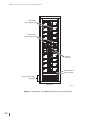
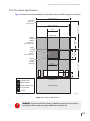
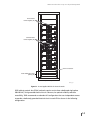
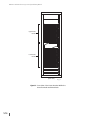
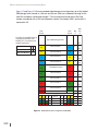
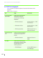
The 3PAR InServ E-Class and F-Class Storage Servers are comprised of the following
components:
■
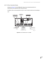
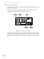
Controller Nodes are high-performance, data movement engines that provide the
caching capabilities and manage the flow of data in a storage server. The E200 and F200
Storage Servers use two controller nodes while the F400 uses either a two or four node
configuration. It should be noted that the E-Class uses an earlier model of controller node
than the F-Class.
■
3PAR Storage Server Backplane works in conjunction with the controller nodes to route
data. This passive, full-mesh backplane enables high-bandwidth and low-latency internal
pathing that supersedes bus-, switch-, and even InfiniBand-based architectures.
■
Drive Chassis houses the drive cages that, in turn, contain the drive bays. Each drive bay
can accommodate a single drive magazine. These are intelligent, compact, extremely dense
storage units, where each is capable of holding a large numbers of hard disk drives in a
small rack space (EIA-standard rack units).
■
Fibre Channel Adapters and FCAL modules provide high speed routing of data and
enable granular connectivity to hosts and to the drive chassis.
■
Storage Server Service Processor provides the remote error detection and reporting
capabilities that support diagnostic and maintenance activities involving InServ Storage
Servers. In general, one service processor is required per InServ Storage Server.
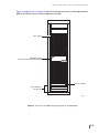
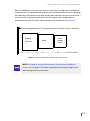
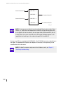
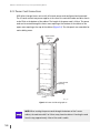
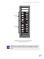
NOTE: The E-Class components can be housed in either a 1 meter or 2 meter
cabinet while the F-Class components are only available in a 2 meter cabinet.
For details on third-party rack configurations, see Chapter 7, Third-Party Rack
Mounting.
2.2