1
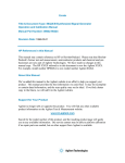
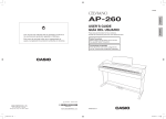
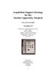
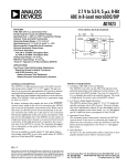
*TB 9-6625-2049-35
SUPERSEDED COPY DATED 15 JANUARY 1996
DEPARTMENT OF THE ARMY TECHNICAL BULLETIN
CALIBRATION PROCEDURE FOR
SYNTHESIZER/FUNCTION GENERATOR
HEWLETT-PACKARD
MODELS 3325A( ) AND 3325B( )
Headquarters, Department of the Army, Washington, DC
2 January 2001
Approved for public release; distribution is unlimited
REPORTING OF ERRORS AND RECOMMENDED IMPROVEMENTS
You can help improve this publication. If you find any mistakes or if you
know of a way to improve the procedure, please let us know. Mail your letter
or DA Form 2028 to: Commander, U. S. Army Aviation and Missile
Command, ATTN: AMSAM-MMC-LS-LP, Redstone Arsenal, AL 35898-5230.
A reply will be furnished to you. You may also send in your comments
electronically to our e-mail address: [email protected] or by FAX (256)
842-6546/DSN 788-6546
SECTION
I.
II.
III
Paragraph
Page
1
2
3
2
2
2
EQUIPMENT REQUIREMENTS
Equipment required............................................
Accessories required ...........................................
CALIBRATION PROCESS
4
5
4
5
Preliminary instructions.....................................
Equipment setup.................................................
Harmonic distortion............................................
Amplitude modulation distortion........................
Square wave characteristics ...............................
Ramp retrace.......................................................
Frequency accuracy ............................................
Phase increment .................................................
Sine wave amplitude and flatness ......................
Square wave amplitude and flatness..................
6
7
8
9
10
11
12
13
14
15
6
6
7
9
9
10
11
13
14
16
IDENTIFICATION AND DESCRIPTION
Test instrument identification............................
Forms, records, and reports................................
Calibration description .......................................
__________
*This bulletin supersedes TB 9-6625-2049-35, 15 January 1996.
TB 9-6625-2049-35
SECTION
II
Paragraph
Page
16
17
18
19
20
21
17
18
19
20
21
22
CALIBRATION PROCESS - Continued
I.
Triangle and ramp amplitude ............................
Dc offset...............................................................
Dc offset with ac ..................................................
High voltage output option 002 only...................
Power supply .......................................................
Final procedure ...................................................
SECTION I
IDENTIFICATION AND DESCRIPTION
1. Test Instrument Identification.
This bulletin provides instructions for the
calibration of Synthesizer/Function Generator, Hewlett-Packard, Models 3325A( ) and
3325B( ). The manufacturer's manuals and TM 11-6625-3065-14 were used as the prime
data sources in compiling these instructions. The equipment being calibrated will be
referred to as the TI (test instrument) throughout this bulletin.
a. Model Variations. Option 001: High Stability Frequency Reference; Option 002:
High Voltage Output; Option E04: includes Options 001, 002, and instrument front
handles and chassis slides; Option 907: Front Handle Assembly; Option 908: Rack Mount
Flange Kit; Option 909: Rack Mount Flange Kit/Front Handle Assembly; Option 910:
Additional Operating and Service Manual. Variations among models are described in text,
tables, and figures.
b. Time and Technique. The time required for this calibration is approximately 4
hours, using the dc and low frequency technique.
2. Forms, Records, and Reports
a. Forms, records and reports required for calibration personnel at all levels are
prescribed by TB 750-25.
b. Adjustments to be reported are designated (R) at the end of the sentence in which
they appear. When adjustments are in tables, the (R) follows the designated adjustment.
Report only those adjustments made and designated with (R).
3. Calibration Description. TI parameters and performance specifications which
pertain to this calibration are in table 1.
2
TB 9-6625-2049-35
Test instrument parameters
Harmonic distortion1
(relative to fundamental at
full output)
Amplitude modulation
Square wave
Ramp retrace
Frequency
Sine wave
Square wave
Triangle
Positive slope ramp
Negative slope ramp
Phase offset
Amplitude
Amplitude accuracy with no
attenuation (attenuator range 1)
into 50Ω load (no dc offset )
Flatness with no attenuation
(attenuator range 1) into a 50Ω load
See footnotes at end of table.
Table 1. Calibration Description
Performance specifications
Fundamental frequency: 0.1 Hz To 50 kHz
Accuracy: No harmonic greater than -65 dB
Fundamental frequency: 50 to 200 kHz
Accuracy: No harmonic greater than -60 dB
Fundamental frequency: 200 kHz to 2 MHz (200 kHz to 1 MHz
for option 002)
Accuracy: No harmonic greater than -40 dB
Fundamental frequency: 2 to 15 MHz
Accuracy: No harmonic greater than -30 dB
Fundamental frequency: 15 to 20 MHz
Accuracy: No harmonic greater than -25 dB
AM distortion: ≤-30 dB at 80% modulation, 10 kHz, and 0 V dc
offset
Rise time and fall time: ≤20 ns, (≤125 ns for option 002) at full
output
Symmetry: ≤.02% of period +3 ns
Overshoot: ≤5% of p-p amplitude at full output (<10% of peak
amplitude for option 002)
≤3 µs retrace time, positive or negative ramps
Accuracy: 5 x 10⁻⁶ of selected value
Range: 1 µHz to 20 999 999.999 Hz
(option 002: .02 Hz to 25.6 kHz)
Range: 1 µHz to 10 999 999.999 Hz
(option 002: .02 Hz to 25.6 kHz)
Range: 1 µHz to 10 999 999.999 Hz
(option 002: .02 Hz to 10 kHz)
Range: 1 µHz to 10 999 999.999 Hz
(option 002: .02 Hz to 10 kHz)
Range: 1 µHz to 10 999 999.999 Hz
(option 002: .02 Hz to 10 kHz)
Range: Variable ±719.9° with respect to arbitrary starting
phase,
or assigned zero phase
Accuracy: ±0.2°
Tolerance relative to
programmed amplitude
Sine wave: .001 Hz to 100 kHz2 ±0.1 dB
Square wave: .001 Hz to 100 kHz
±1.0%
Triangle: .001 Hz to 2 kHz
±1.5%
2 kHz to 10 kHz
±5%
Ramps: .001 Hz to 500 Hz
±1.5%
500 Hz to 10 kHz
±10%
Tolerance relative to
programmed amplitude at 1 kHz
Sine wave: 100 kHz to 20 ±0.3 dB
MHz
Square wave: 100 kHz to 10 MHz ±10%
3
TB 9-6625-2049-35
Table 1. Calibration Description - Continued
Test instrument parameters
Performance specifications
Tolerance relative to
Amplitude accuracy with dc
programmed amplitude
offset and
no
attenuation
(range 1)
into 50Ω load
Sine wave: .001 Hz to 100 kHz
±0.3 dB
Square: .001 Hz to 100 kHz
±3%
Triangle: .001 Hz to 2 kHz
±4%
2 kHz to 10 kHz
±6%
Ramps: .001 Hz to 500 Hz
±4%
500 Hz to 10 kHz
±11%
Tolerance relative to
Function and frequency range
programmed amplitude
Attenuator accuracy (these .001 Hz to 100 kHz
±0.1 dB
Attenuator ranges 2 through 8
errors are additive with the
amplitude accuracy errors)
Amplitude output
Amplitude (option 002)
(high voltage output)
Dc offset
Dc offset (option 002)
Dc plus ac
1Not
100 kHz to 10 MHz
±0.2 dB
Attenuator ranges 2 through 8
10 MHz to 20 MHz
Attenuator ranges 2 through 4
0.2 dB
Attenuator ranges 5 through 8 ±0.5 dB
Range: 1.000 mV to 10.00 V p-p
Range: 4 mV to 40 V p-p (>500Ω)
Accuracy: +2% of full output for each range at 2 kHz
Flatness: +10% of programmed amplitude
Range: +5 V dc
Accuracy: +0.4% of full peak output for each attenuator range2
Range: +20 V dc
Accuracy: + (1% +25 mV) of full output for each attenuator range
Range: <1 MHz
Accuracy: +1.2%
Ramps: +2.4%
Range: >1 MHz
Accuracy: +3%
verified below 50 Hz.
lowest attenuator range where accuracy is ±20 µV.
2Except
SECTION II
EQUIPMENT REQUIREMENTS
4. Equipment Required. Table 2. identifies the specific equipment to be used in this
calibration procedure. This equipment is issued with Secondary Transfer Calibration
Standards Set AN/GSM-287. Alternate items may be used by the calibrating activity. The
item selected must be verified to perform satisfactorily prior to use and must bear evidence
of current calibration. The equipment must meet or exceed the minimum use specifications
listed in table 2. The accuracies listed in table 2 provide a four-to-one ratio between the
standard and TI.
4
TB 9-6625-2049-35
5. Accessories Required. The accessories required for this calibration are common
usage accessories, issued as indicated in paragraph 4 above, and are not listed in this
calibration procedure. The following peculiar accessory is also required for this calibration:
50Ω feedthrough termination, Hewlett-Packard, Model 11048C.
Table 2. Minimum Specifications of Equipment Required
Common name
AUDIO ANALYZER
FREQUENCY COUNTER
MEASURING RECEIVER
Minimum use specifications
Output: 4.5 V, 10 kHz
AM distortion: ≤-30 dB at 10 kHz Distortion:
≤-60 dB at 50 Hz
Range: 99,9950 µs to 60,000,300 Hz
Accuracy: 1.25 x 10⁻⁸
Capability: Time interval A to B
Frequency: 100 kHz to 10 MHz
Volts: .683 to .732 V rms
Accuracy: ±0.85%
AM: 0 to 80%
Manufacturer and model
(part number)
Boonton, Model 1120-S/10
(MIS-35954/2)
Hewlett-Packard, Model 5345A
(MIS-28754/1 Type 1)
Consisting of : Measuring
receiver
Hewlett-Packard,
Model 8902A and Sensor
module Hewlett-Packard, Model
11722A
MULTIMETER
Range: -20.225 to +20.225 V dc
Accuracy: ±0.05%
Range: 0.3416 to 20.4 V ac
100 Hz to 100 kHz
Accuracy: ±0.3%
Hewlett-Packard, Model
3458A
OSCILLOSCOPE
Frequency: 1 kHz to 10 MHz
Amplitude: 1.8 to 2.2 V p-p
Accuracy: ±2.5%
Capabilities
Duty cycle: 49.7 to 50.3%
Overshoot: 5%
Rise time and fall time: <20 ns
Tektronix, Type 2430A
(OS-291/G)
SPECTRUM ANALYZER
Frequency: 50 kHz to 20 MHz
Input: -20 dBm and 40 V
Display capability: <-65 dBc
(AN/USM-489A(V)1)
SYNTHESIZER/LEVEL
GENERATOR
Frequency: 0.1 MHz
Amplitude: 13 dBm
TIME FREQUENCY
WORKSTATION
RESISTANCE STANDARD
Reference output frequency: 10 MHz
Accuracy: ±5 x 10⁻⁸
Range: 470Ω
Hewlett-Packard, Model
3335AOPT 001-K06
(MIS-35938)
Autek Systems Corporation,
Model 620 (MIS-38946)
Biddle Gray, Model 71-631
(7910328)
5
TB 9-6625-2049-35
SECTION III
CALIBRATION PROCESS
6. Preliminary Instructions
a. The instructions outlined in paragraphs 6 and 7 are preparatory to the calibration
process. Personnel should become familiar with the entire bulletin before beginning the
calibration.
b. Items of equipment used in this procedure are referenced within the text by common
name as listed in table 2.
c. Unless otherwise specified, verify the result of each test and, whenever the test
requirement is not met, take corrective action before continuing with the calibration.
Adjustments required to calibrate the TI are included in this procedure. Additional
maintenance information is contained in TM 11-6625-3065-14 and the manufacturer's
manual for this TI.
d. When indications specified in paragraphs 8 through 19 are not within tolerance,
perform the power supply check prior to making adjustments.
After adjustments are
made, repeat paragraphs 8 through 19. Do not perform power supply check if all other
parameters are within tolerance.
e. Unless otherwise specified, all controls and control settings refer to the TI.
7. Equipment Setup
WARNING
HIGH VOLTAGE is used or exposed during the performance of
this calibration.
DEATH ON CONTACT may result if
personnel fail to observe safety precautions.
REDUCE
OUTPUT(S) to minimum after each step within the
performance check where applicable.
CAUTION
Before connecting TI to power source, make sure TI is set to
the power source line voltage shown on rear of TI.
a. Connect TI to a 115 V ac source. Press POWER pushbutton to ON and allow at
least 24 hours (72 hours for option 001) for warmup.
b. Before continuing, review (1) through (4) below:
(1) The SWEEP LINEAR/LOG, ENTRY, FUNCTION, SIGNAL, and blue keys
each have an indicator denoting that it is activated.
(2) When power is applied to the TI, some keys will be lit.
(3) Pressing any FUNCTION key that is active will delete that function and no ac
signal will be present at the output.
(4) Some instructions will be repeated during programming. This is done to ensure
correct output is available.
6
TB 9-6625-2049-35
8. Harmonic Distortion
a. Performance Check
(1) Connect TI EXT REF IN 1, 10 MHz to spectrum analyzer 10 MHz REF
IN/OUT.
(2) Connect TI SIGNAL to spectrum analyzer INPUT 50Ω
Ω.
(3) Press keys and enter values using DATA keys as listed in (a) through (h) below:
(a)
(b)
(c)
(d)
(e)
(f)
(g)
(h)
SIGNAL off (option 002 not lit).
FUNCTION sine wave.
ENTRY AMPTD.
-20 dBm.
ENTRY DC OFFSET.
0 VOLT.
ENTRY FREQ.
20 MHz.
(4) Adjust spectrum analyzer controls to display 20 MHz fundamental and at least
four harmonics. All harmonics will be at least 25 dB below fundamental.
(5) Enter 14 MHz using TI DATA keys. Adjust spectrum analyzer controls to
display 14 MHz fundamental and at least four harmonics. All harmonics will be at least 30
dB below fundamental.
(6) Enter 1.9 MHz using TI DATA keys. Adjust spectrum analyzer controls to
display 1.9 MHz fundamental and at least four harmonics. All harmonics will be at least
40 dB below fundamental.
(7) Enter 190 kHz using TI DATA keys. Adjust spectrum analyzer controls to
display 190 kHz fundamental and at least four harmonics. All harmonics will be at least
60 dB below fundamental.
(8) Enter 100 kHz using TI DATA keys. Adjust spectrum analyzer controls to
display 100 kHz fundamental and at least four harmonics. All harmonics will be at least
60 dB below fundamental.
(9) Enter 40 kHz using TI DATA keys. Adjust spectrum analyzer controls to
display 40 kHz fundamental and at least four harmonics. All harmonics will be at least 65
dB below fundamental.
(10) Disconnect TI from spectrum analyzer.
(11) Connect TI SIGNAL to audio analyzer INPUT HIGH using 50Ω feedthrough
termination.
(12) Press keys and enter values using DATA keys as listed in (a) through (c) below:
7
TB 9-6625-2049-35
(a) 50 Hz.
(b) ENTRY AMPTD.
(c) 10 VOLT.
(13) Set audio analyzer to measure distortion in dB. Audio analyzer indication will
be ≤-65 dB.
(14) Perform (15) through (19) below for option 002 only.
(15) Connect equipment as shown in figure 1 and set resistance standard to 470Ω.
Figure 1. Harmonic distortion - equipment setup.
(16) Press keys and enter values using DATA keys as listed in (a) through (e) below:
(a)
(b)
(c)
(d)
(e)
SIGNAL on.
ENTRY FREQ.
25 kHz.
ENTRY AMPTD.
40 VOLT.
(17) Adjust spectrum analyzer controls to display 25 kHz fundamental and at least
four harmonics. All harmonics will be at least 65 dB below fundamental.
(18) Press ENTRY FREQ key and enter 190 kHz using DATA keys. Adjust
spectrum analyzer controls to display 190 kHz fundamental and at least four harmonics.
All harmonics will be at least 60 dB below fundamental.
(19) Enter 1 MHz using DATA keys. Adjust spectrum analyzer controls to display 1
MHz fundamental and at least four harmonics. All harmonics will be at least 40 dB below
fundamental.
b. Adjustment. No adjustments can be made.
8
TB 9-6625-2049-35
9. Amplitude Modulation Distortion
a. Performance Check
(1) Press keys and enter values using DATA keys as listed in (a) through (i) below:
(a) SIGNAL off (option 002 not lit).
(b) FUNCTION sine wave.
(c) ENTRY FREQ.
(d) 1 MHz.
(e) ENTRY AMPTD.
(f) 3 VOLT.
(g) ENTRY DC OFFSET.
(h) 0 VOLT.
(i) Blue then AM ON.
(2) Connect equipment as shown in figure 2.
Figure 2. AM distortion - equipment setup.
(3) Set audio analyzer for a 50Ω (SPCL 75), 10 kHz, 2.5 V output.
(4) Set measuring receiver to measure AM.
(5) Adjust audio analyzer level until measuring receiver indicates 80%.
(6) Set audio analyzer to measure distortion in dB. Audio analyzer indication will
be ≤-30 dB.
(7) Press TI blue key then DATA AM OFF key.
b. Adjustments. No adjustments can be made.
10. Square Wave Characteristics
a. Performance Check
(1) Press keys and enter values using DATA keys as listed in (a) through (f) below:
9
TB 9-6625-2049-35
(a)
(b)
(c)
(d)
(e)
(f)
SIGNAL off (option 002 not lit).
FUNCTION square wave.
ENTRY FREQ.
1 MHz.
ENTRY AMPTD.
1 V RMS.
(2) Connect TI SIGNAL to oscilloscope CH 1.
(3) Set oscilloscope CH 1 COUPLING 50Ω
Ω to ON.
(4) Set oscilloscope controls for duty cycle measurement. Duty cycle will be between
49.7 and 50.3 percent.
(5) Enter 10 VOLT using DATA keys.
(6) Set oscilloscope controls for rise time measurement. Rise time will be ≤20 ns.
(7) Repeat (6) above for fall time.
(8) Set oscilloscope controls for overshoot measurement. Overshoot will be ≤5
percent of peak to peak amplitude (≤500 mV at positive and negative peaks).
(9) Perform (10) through (12) below for option 002 only.
(10) Set oscilloscope CH 1 COUPLING 50Ω
Ω to OFF.
(11) Press TI SIGNAL key on (lit).
(12) Repeat technique in (6) through (8) above. Rise time and fall time will be
≤125 ns with an overshoot <10 percent of peak amplitude (<500 mV at positive and
negative peaks).
b. Adjustments. No adjustments can be made.
11. Ramp Retrace
a. Performance Check
(1) Connect TI SIGNAL to oscilloscope CH 1.
(2) Set oscilloscope CH 1 COUPLING 50Ω
Ω to ON.
(3) Press keys and enter values using DATA keys as listed in (a) through (f) below:
(a)
(b)
(c)
(d)
(e)
(f)
10
SIGNAL off (option 002 not lit).
FUNCTION positive ramp.
ENTRY FREQ.
10 kHz.
ENTRY AMPTD.
10 VOLT.
TB 9-6625-2049-35
(4) Set oscilloscope controls to measure ramp retrace time from the 90 to 10 percent
points. Ramp retrace time will be ≤3 µs.
(5) Press FUNCTION negative ramp key and repeat (4) above.
b. Adjustments. No adjustments can be made.
12. Frequency Accuracy
a. Performance Check
(1) Connect TI SIGNAL to frequency counter CHANNEL A.
(2) Press keys and enter values using DATA keys as listed in (a) through (f) below:
(a)
(b)
(c)
(d)
(e)
(f)
SIGNAL off (option 002 not lit).
FUNCTION sine wave.
ENTRY FREQ.
20 MHz.
ENTRY AMPTD.
.99 VOLT.
(3) Set frequency counter 50Ω
Ω /1MΩ
Ω switch to 50Ω
Ω.
(4) Set frequency counter controls to measure frequency. If frequency counter does
not indicate between 19.99990 and 20.00010 MHz, perform b below.
(5) Press FUNCTION square wave key. Frequency counter will indicate between
9.999950 and 10.000050 MHz.
(6) Disconnect frequency counter from TI SIGNAL.
(7) Connect frequency counter CHANNEL A to TI SYNC OUT.
(8) Press TI FUNCTION triangle key.
(9) Set frequency counter controls to measure period.
indicate between 99.99950 and 100.00050 µs.
Frequency counter will
(10) Press FUNCTION positive ramp key. Frequency counter will indicate between
99.99950 and 100.00050 µs.
(11) Press FUNCTION negative ramp key. Frequency counter will indicate between
99.99950 and 100.00050 µs.
(12) Disconnect frequency counter from TI SYNC OUT.
(13) Connect frequency counter to TI AUX 21-60 MHz (rear panel).
(14) Press keys and enter values using DATA keys as listed in (a) through (c) below:
(a) FUNCTION sine wave.
(b) ENTRY FREQ.
(c) 60 MHz.
11
TB 9-6625-2049-35
(15) Set frequency counter controls to measure frequency. If frequency counter does
not indicate between 59.99970 and 60.00030 MHz, perform b below.
b. Adjustments
(1) Disconnect TI rear panel 10 MHz OVEN OUTPUT from EXT REF IN option
001 only.
(2) Connect frequency counter CHANNEL A to TI rear panel AUX 21-60 MHz.
(3) Press keys and enter values using DATA keys as listed in (a) through (c) below:
(a) FUNCTION sine wave.
(b) ENTRY FREQ.
(c) 60 MHz.
(4) Adjust REF R30 (fig. 3) until frequency counter indicates 60.000000 MHz (R).
Figure 3. Test instrument - bottom view.
(5) Disconnect frequency counter from TI rear panel AUX 21-60 MHz.
(6) Connect frequency counter CHANNEL A to TI SIGNAL.
(7) Enter 20 MHz using DATA keys. Frequency counter will indicate between
19.99990 and 20.00010 MHz.
(8) Disconnect frequency counter from TI.
(9) Perform (10) through (14) below for option 001 only.
(10) Connect time/frequency workstation OUTPUT 1 MHz to frequency difference
meter REF INPUT.
(11) Connect TI rear panel 10 MHz OVEN OUTPUT to frequency difference meter
SIG INPUT.
12
TB 9-6625-2049-35
(12) Adjust A9R7 Fine Adj. (fig. 3) and A9 Coarse Adj. (fig. 3) for a minimum
indication on frequency difference meter.
(13) Disconnect TI from frequency difference meter.
(14) Reconnect TI rear panel 10 MHz OVEN OUTPUT to EXT REF IN.
13. Phase Increment
a. Performance Check
(1) Press keys and enter values using DATA keys as listed in (a) through (f) below:
(a)
(b)
(c)
(d)
(e)
(f)
SIGNAL off (option 002 not lit).
FUNCTION sine wave.
ENTRY FREQ.
100 kHz.
ENTRY AMPTD.
13 dBm.
(2) Connect equipment as shown in figure 4.
Figure 4. Phase increment - equipment setup.
NOTE
If TI has option 001, remove the connection from 10 MHz
OUTPUT to EXT REF IN (rear panel) (fig. 4).
(3) Set synthesizer/level generator frequency to .1 MHz and amplitude to 13 dBm.
(4) Set frequency counter controls for time interval A to B measurement.
(5) Press keys as listed in (a) through (c) below:
(a) ENTRY PHASE.
(b) MODIFY until frequency counter indicates between 199 and 201 ns.
(c) Blue then ASGN ZERO PHASE.
13
TB 9-6625-2049-35
(6) Adjust frequency counter sample rate control to HOLD and press RESET
pushbutton. Record frequency counter indication.
(7) Press ENTRY PHASE key and enter -1 deg using DATA keys.
(8) Press frequency counter RESET pushbutton and record frequency counter
indication.
(9) Determine the difference between indication recorded in (6) above and indication
recorded in (8) above. The difference will be between 22.22 and 33.34 ns.
(10) Enter -10 deg using DATA keys.
(11) Press frequency counter RESET pushbutton and record frequency counter
indication.
(12) Determine the difference between indication recorded in (6) above and indication
recorded in (11) above. The difference will be between 272.22 and 283.34 ns.
(13) Enter -100 deg using DATA keys.
(14) Press frequency counter RESET pushbutton and record frequency counter
indication.
(15) Determine the difference between indication recorded in (6) above and indication
recorded in (14) above. The difference will be between 2722.22 and 2783.34 ns.
b. Adjustments. No adjustments can be made.
14. Sine wave Amplitude and Flatness
a. Performance Check
(1) Connect TI SIGNAL to multimeter INPUT HI and LO using 50Ω feedthrough
termination.
(2) Press keys and enter values using DATA keys as listed in (a) through (i) below:
(a)
(b)
(c)
(d)
(e)
(f)
(g)
(h)
(i)
SIGNAL off (option 002 not lit).
ENTRY DC OFFSET.
0 VOLT.
FUNCTION sine wave.
ENTRY AMPTD.
3.536 V RMS.
ENTRY FREQ.
100 Hz.
AMPTD CAL.
(3) Multimeter will indicate between 3.495 and 3.577 V ac.
(4) Repeat technique of (2)(e) through (i) and (3) above using TI settings and
multimeter indications listed in table 3.
14
TB 9-6625-2049-35
Table 3. Amplitude
Test instrument settings
Multimeter indications
(V ac)
ENTRY AMPTD
ENTRY FREQ
3.536
V RMS
1 kHz
3.495
3.577
3.536
V RMS
100 kHz
3.495
3.577
1.061
V RMS
100 kHz
1.048
1.073
1.061
V RMS
1 kHz
1.048
1.073
1.061
V RMS
100 Hz
1.048
1.073
.3536
V RMS1
100 Hz
0.3416
0.3660
.3536
V RMS
1 kHz
0.3416
0.3660
.3536
V RMS
100 kHz
0.3416
0.3660
1Press
ENTRY DC OFFSET key and enter 1 mV using DATA keys.
(5) Press keys and enter values using DATA keys as listed in (a) through (g) below:
(a)
(b)
(c)
(d)
(e)
(f)
(g)
ENTRY DC OFFSET.
0 mV.
ENTRY FREQ.
1 kHz.
ENTRY AMPTD.
.707 V RMS.
AMPTD CAL.
(6) Press MODIFY keys for a multimeter indication as close as possible to 0.707 V
ac.
(7) Enter 100 kHz using DATA keys. Multimeter will indicate between 0.683
and 0.732 V ac. Record multimeter indication.
(8) Disconnect multimeter and 50Ω feedthrough termination from TI.
NOTE
If necessary, ZERO and CALIBRATE measuring receiver and
sensor module.
(9) Connect measuring receiver sensor module to TI SIGNAL.
(10) Set measuring receiver to measure volts at .1 MHz.
(11) Press ENTRY AMPTD key.
(12) Press MODIFY keys for a measuring receiver indication as close as possible to
indication recorded in (7) above.
(13) Press ENTRY FREQ key and enter 500 kHz using DATA keys.
(14) Set measuring receiver to measure volts at .5 MHz. Measuring receiver will
indicate between 0.683 and 0.732 V.
(15) Repeat technique of (13) and (14) above using TI and measuring receiver
settings listed in table 4. Measuring receiver will indicate between 0.683 and 0.732 V.
15
TB 9-6625-2049-35
Table 4. Flatness
Test instrument
and measuring receiver
settings (MHz)
1
2
4
6
8
10
12
14
16
18
20
b. Adjustments. No adjustments can be made.
15. Square Wave Amplitude and Flatness
a. Performance Check
(1) Connect TI SIGNAL to multimeter INPUT HI and LO using 50Ω feedthrough
termination.
(2) Press keys and enter values using DATA keys as listed in (a) through (i) below:
(a)
(b)
(c)
(d)
(e)
(f)
(g)
(h)
(i)
SIGNAL off (option 002 not lit).
ENTRY DC OFFSET.
0 VOLT.
FUNCTION square wave.
ENTRY AMPTD.
5 V RMS.
ENTRY FREQ.
100 Hz.
AMPTD CAL.
(3) Multimeter will indicate between 4.95 and 5.05 V ac.
(4) Enter 1 kHz using DATA keys. Multimeter will indicate between 4.95 and 5.05
V ac.
(5) Enter 100 kHz using DATA keys. Multimeter will indicate between 4.95 and
5.05 V ac.
(6) Press keys and enter values using DATA keys as listed in (a) through (d) below:
16
TB 9-6625-2049-35
(a)
(b)
(c)
(d)
1 kHz.
ENTRY AMPTD.
1 V RMS.
AMPTD CAL.
(7) Multimeter will indicate between 0.99 and 1.01 V ac.
(8) Disconnect TI from multimeter.
(9) Connect TI SIGNAL to oscilloscope CH 1 using 50Ω feedthrough termination.
(10) Set oscilloscope controls to measure square wave amplitude. Record oscilloscope
indication.
(11) Press ENTRY FREQ key and enter 1 MHz using DATA keys.
(12) Set oscilloscope controls to measure square wave amplitude. Oscilloscope
indication will be within ±10 percent of indication recorded in (10) above.
(13) Enter 3 MHz using DATA keys and repeat (12) above.
(14) Enter 5 MHz using DATA keys and repeat (12) above.
(15) Enter 10 MHz using DATA keys and repeat (12) above.
b. Adjustments. No adjustments can be made.
16. Triangle and Ramp Amplitude
a. Performance Check
(1) Connect TI SIGNAL to multimeter INPUT HI and LO using 50Ω feedthrough
termination.
(2) Press keys and enter values using DATA keys as listed in (a) through (i) below:
(a)
(b)
(c)
(d)
(e)
(f)
(g)
(h)
(i)
SIGNAL off (option 002 not lit).
ENTRY DC OFFSET.
0 VOLT.
FUNCTION triangle.
ENTRY AMPTD.
2.887 V RMS.
ENTRY FREQ.
100 Hz.
AMPTD CAL.
(3) Multimeter will indicate between 2.843 and 2.931 V ac.
(4) Enter 1.9 kHz using DATA keys. Multimeter will indicate between 2.843 and
2.931 V ac.
(5) Enter 2.1 kHz using DATA keys. Multimeter will indicate between 2.742 and
3.032 V ac.
17
TB 9-6625-2049-35
(6) Enter 10 kHz using DATA keys. Multimeter will indicate between 2.742 and
3.032 V ac.
(7) Press keys and enter values using DATA keys as listed in (a) through (c) below:
(a) FUNCTION positive ramp.
(b) 100 Hz.
(c) AMPTD CAL.
(8) Multimeter will indicate between 2.843 and 2.931 V ac.
(9) Enter 499 Hz using DATA keys. Multimeter will indicate between 2.843 and
2.931 V ac.
(10) Enter 501 Hz using DATA keys. Multimeter will indicate between 2.598 and
3.176 V ac.
(11) Enter 10 kHz using DATA keys. Multimeter will indicate between 2.598 and
3.176V ac.
b. Adjustments. No adjustments can be made.
17. Dc Offset
a. Performance Check
(1) Connect TI SIGNAL to multimeter INPUT HI and LO using 50Ω feedthrough
termination.
(2) Press SIGNAL key off (option 002 not lit).
(3) Press presently active FUNCTION key to remove ac output and activate
ENTRY DC OFFSET key (lit).
(4) Enter 5 VOLT using DATA keys and press AMPTD CAL key.
(5) Multimeter will indicate between 4.98 and 5.02 V dc.
(6) Enter -5 VOLT using DATA keys. Multimeter will indicate between -4.98
and -5.02 V dc.
(7) Repeat technique of (6) above using TI settings and multimeter indications
listed in table 5.
Table 5. Dc Offset
Test instrument
Multimeter indications
(V dc)
DC OFFSET
settings
Min
Max
1.499
VOLT
1.493
1.505
-1.499
VOLT
-1.505
-1.493
499.9
mV
0.4979
0.5019
-499.9
mV
-0.5019
-0.4979
149.9
mV
0.1493
0.1505
-149.9
mV
-0.1505
-0.1493
49.99
mV
0.04979
0.05019
-49.99
mV
-0.05019
-0.04979
18
TB 9-6625-2049-35
Table 5. Dc Offset - Continued
Test instrument
Multimeter indications
(V dc)
DC OFFSET
settings
Min
Max
14.99
mV
0.01493
0.01505
-14.99
mV
-0.01505
-0.01493
4.999
mV
0.004979
0.005019
-4.999
mV
-0.005019
-0.004979
1.499
mV
0.001479
0.001519
-1.499
mV
-0.001519
-0.001479
NOTE
Perform (8) through (11) below for option 002 only.
(8) Remove 50Ω feedthrough termination from equipment setup.
(9) Press SIGNAL key on.
(10) Enter 20 VOLT using DATA keys. Multimeter will indicate between 19.775
and 20.225 V dc.
(11) Enter -20 VOLT using DATA keys. Multimeter will indicate between -19.775
and -20.225 V dc.
b. Adjustments. No adjustments can be made.
18. Dc Offset with Ac
a. Performance Check
(1) Connect SIGNAL to multimeter INPUT HI and LO using 50Ω feedthrough
termination.
(2) Press keys and enter values using DATA keys as listed in (a) through (i) below:
(a)
(b)
(c)
(d)
(e)
(f)
(g)
(h)
(i)
SIGNAL off (option 002 not lit).
FUNCTION sine wave.
ENTRY FREQ.
20.999 999 999 MHz.
ENTRY AMPTD.
1 VOLT.
ENTRY DC OFFSET.
4.5 VOLT.
AMPTD CAL.
(3) Multimeter will indicate between 4.35 and 4.65 V dc.
19
TB 9-6625-2049-35
(4) Enter -4.5 VOLT using DATA keys. Multimeter will indicate between -4.35 and
-4.65 V dc.
(5) Press ENTRY FREQ key and enter 999.9 kHz using DATA keys. Multimeter
will indicate between -4.44 and -4.56 V dc.
(6) Press ENTRY DC OFFSET key and enter 4.5 VOLT using DATA keys.
Multimeter will indicate between 4.44 and 4.56 V dc.
(7) Press FUNCTION square wave key. Multimeter will indicate between 4.44 and
4.56 V dc.
(8) Enter -4.5 VOLT using DATA keys. Multimeter will indicate between -4.44 and
-4.56 V dc.
(9) Press ENTRY FREQ key and enter 9.9999 MHz using DATA keys.
Multimeter will indicate between -4.35 and -4.65 V dc.
(10) Press FUNCTION triangle key and enter 9.9 kHz using DATA keys.
(11) Multimeter will indicate between -4.44 and -4.56 V dc.
(12) Press FUNCTION positive ramp key. Multimeter will indicate between -4.38
and -4.62 V dc.
b. Adjustments. No adjustments can be made.
19. High Voltage Output Option 002 only
a. Performance Check
(1) Connect SIGNAL to multimeter INPUT HI and LO.
(2) Press keys and enter values using DATA keys as listed in (a) through (i) below:
(a)
(b)
(c)
(d)
(e)
(f)
(g)
(h)
(i)
FUNCTION sine wave.
ENTRY FREQ.
2 kHz.
SIGNAL on.
ENTRY DC OFFSET.
0 VOLT.
ENTRY AMPTD.
14.14 V RMS.
AMPTD CAL.
(3) Multimeter will indicate between 13.86 and 14.42 V ac.
(4) Press keys and enter values using DATA keys as listed in (a) through (e) below:
20
TB 9-6625-2049-35
(a)
(b)
(c)
(d)
(e)
ENTRY FREQ.
100 kHz.
ENTRY AMPTD.
10 V RMS.
AMPTD CAL.
(5) Multimeter will indicate between 9 and 11 V ac.
(6) Press keys and enter values using DATA keys as listed in (a) through (f) below:
(a)
(b)
(c)
(d)
(e)
(f)
FUNCTION square wave.
ENTRY FREQ.
2 kHz.
ENTRY AMPTD.
20 V RMS.
AMPTD CAL.
(7) Multimeter will indicate between 19.6 and 20.4 V ac.
(8) Press FUNCTION triangle key and enter 11.5 V RMS using DATA keys.
(9) Press AMPTD CAL key. Multimeter will indicate between 11.27 and 11.73 V ac.
(10) Press FUNCTION positive ramp key and repeat (9) above.
b. Adjustments. No adjustments can be made.
20. Power Supply
NOTE
Do not perform power supply check if all other parameters are
within tolerance.
a. Performance Check
(1) Connect multimeter INPUT HI to -15 V TP (fig. 5) and LO to ground side of C9
(fig. 5). Adjust R22 (fig. 5) for a multimeter indication of -14.97 to -15.03 V dc (R).
(2) Connect multimeter INPUT HI to +15 V TP (fig. 5). Readjust R22 (fig. 5) if
multimeter does not indicate between 14.9 and 15.1 V dc.
(3) Connect multimeter INPUT HI to +5 V TP (fig. 5). Readjust R22 (fig. 5) if
multimeter does not indicate between 5.01 and 5.05 V dc.
(4) Repeat (1) through (3) above for best in-tolerance condition on all test points.
21
TB 9-6625-2049-35
Figure 5. Power supply assembly A2 – test instrument top view.
(5) Press presently active FUNCTION key to remove ac output and activate
ENTRY DC OFFSET key (lit).
(6) Enter 0 VOLT using DATA keys and press AMPTD CAL key.
(7) Connect multimeter INPUT HI to TP AMP OUT (fig. 3) and LO to circuit board
ground.
NOTE
The voltages measured in (1) through (3) above may be
adjusted out of tolerance by (8) through (11) below. This is not
a cause for concern.
(8) Adjust R40 (fig. 3) until digital multimeter indicates less than 5 mV dc (R).
(9) Connect multimeter INPUT HI and LO to TI SIGNAL.
feedthrough termination.
Do not use 50Ω
(10) Enter 5 VOLT using DATA keys.
(11) Press AMPTD CAL key. Adjust R22 (fig. 5) until multimeter indicates 10.000
V dc.
(12) Enter -5 VOLT using DATA keys.
(13) Multimeter will indicate between -9.985 and -10.015 V dc.
21. Final Procedure
a. Deenergize and disconnect all equipment.
b. Annotate
22
and
affix
DA
label/form
in
accordance
with
TB
750-25.
TB 9-6625-2049-35
By Order of the Secretary of the Army:
Official:
ERIC K. SHINSEKI
General, United States Army
Chief of Staff
JOEL B. HUDSON
Administrative Assistant to the
Secretary of the Army
0029703
DISTRIBUTION:
To be distributed in accordance with IDN 342200, requirements for calibration
procedure TB 9-6625-2049-35.
PIN: 052316-000