1
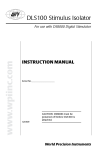
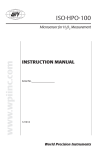
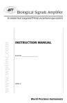
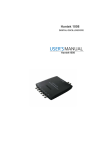
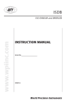
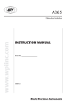
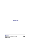
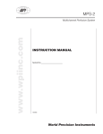
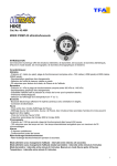
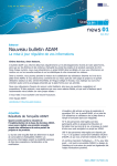
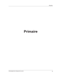
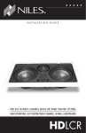
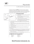
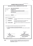
ISO-OXY-2/OXELP www.wpiinc.com Macrosensor for O2 Measurement INSTRUCTION MANUAL Serial No._____________________ 011215 World Precision Instruments Other WPI Favorites Free Radical Analyzer • Real-time detection using electrochemical microsensors • Measure nitric oxide from < 0.3 nM to 100 μM. • Measure hydrogen peroxide < 10 nM to 100 mM • Measure hydrogen sulfide • Measure glucose • Measure oxygen from 0.1% to 100% • Integrated system includes one temperature sensor, your choice of two additional sensors, and a start-up kit • Current measurement range from 300 fA to 10 μA (four ranges) permits wide dynamic range for detection. • Wide bandwidth allows recording of fast events • Isolated architecture allows Lab-Trax interface to simultaneously measure free radical and independent analog data (i.e., ECG, BP, etc.) data on any channel. MACRO SENSORS Carbon Monoxide Nitric Oxide Hydrogen Oxygen Peroxide Hydrogen Sulfide Order Number ISO-COP-2 ISO-NOP ISO-HPO-2 ISO-OXY-2 ISO-H2S-2 Available Diameters 2 mm 2 mm 2 mm 2 mm 2 mm Response Time < 10 sec < 5 sec < 5 sec < 10 sec < 5 sec Detection Limit/Range 10nM to 10μM 1 NM to 40μM* < 100nM to 0.1%-100% 100μM SPECIES Sensitivity ~0.5 pA/nM ≤ 2 pA/nM 8 pA/μM 0.3-0.6nA/% Drift <1pA/min <1pA/min 0.1pA/min < 1%/min Yes < 5nM-100μM 2 pA/nM Temperature Dependent Yes Yes Yes Yes Physiological Interference nitric oxide NaNO2 (10-6 or None better) None None Replacement Sleeves (pkg of 4) #95620 #5436 #600012 #5378 #600016 Filling Solution #95611 #7325 #100042 #7326 #100084 Start-up Kit #95699 #5435 #600011 #5377 #600015 * Higher detection limit available on request — call for custom pricing. ISO-OXY-2/OXELP CONTENTS ABOUT THIS MANUAL ........................................................................................................................ 1 INTRODUCTION.................................................................................................................................... 2 Notes and Warnings....................................................................................................................... 2 INSTRUMENT DESCRIPTION ............................................................................................................ 3 Unpacking......................................................................................................................................... 3 Structure of the Sensor .................................................................................................................. 4 OPERATING INSTRUCTIONS ............................................................................................................. 5 Polarizing the Sensor .................................................................................................................... 5 Calibration Procedure .................................................................................................................... 5 SENSOR CARE AND MAINTENANCE .............................................................................................. 9 Durability and Handling ................................................................................................................ 9 Storing the Sensor .......................................................................................................................... 9 Cleaning the Membrane ............................................................................................................... 9 Sterilizing the Membrane............................................................................................................10 Replacing the Membrane Sleeve ..............................................................................................10 ACCESSORIES......................................................................................................................................12 TROUBLESHOOTING .........................................................................................................................13 Dry Sensor Test..............................................................................................................................13 SPECIFICATIONS .................................................................................................................................14 WARRANTY ..........................................................................................................................................15 Claims and Returns ......................................................................................................................15 Repairs .............................................................................................................................................15 Copyright © 2015 by World Precision Instruments, Inc. All rights reserved. No part of this publication may be reproduced or translated into any language, in any form, without prior written permission of World Precision Instruments, Inc. World Precision Instruments iii iv World Precision Instruments ISO-OXY-2/OXELP ABOUT THIS MANUAL The following symbols are used in this guide: This symbol indicates a CAUTION. Cautions warn against actions that can cause damage to equipment. Please read these carefully. This symbol indicates a WARNING. Warnings alert you to actions that can cause personal injury or pose a physical threat. Please read these carefully. NOTES and TIPS contain helpful information. Fig. 1—The ISO-OXY-2 sensor works with the TBR4100, TBR1025 and Apollo systems. Fig. 2—The OXELP sensor works with the ISO2 only. World Precision Instruments 1 INTRODUCTION The ISO-OXY-2 and the OXELP are 2.0mm oxygen sensors with replaceable stainless steel membrane sleeves filled with an electrolyte solution. Replacement membrane sleeves (pkg. of four) and filling solution can be purchased in a kit (WPI #5378). Filling solution can also be purchase separately (WPI #7326). A startup kit for this sensor is available and is recommended for the first purchase of this sensor type (WPI #5377). With the exception of the connector, the ISO-OXY-2 and the OXELP sensors are identical. The ISO-OXY-2 is designed for use with WPI free radical analyzers, and the OXELP is designed for use with the ISO2 dissolved oxygen meter. Operation, maintenance and specifications are identical for these two sensors, so they will be discussed side-by-side in this manual. These sensor incorporates WPI’s proprietary combination electrode technology whereby the oxygen-sensing element and separate reference electrode are encased within a single shielded sensor design. A gas-permeable polymer membrane is fitted over the end of the sleeve, which allows oxygen to pass while blocking liquids, ions and particulate matter. Oxygen diffuses through the membrane. The voltage applied to the sensor is held at -0.7V when the monitoring device is on and the sensor is properly connected. The magnitude of the generated electrical current is determined by the rate of diffusion through the membrane. The rate is proportional to the partial pressure of oxygen outside the membrane. The current serves as a measure of the partial pressure of O2. Notes and Warnings CAUTION: DO NOT EXPOSE SENSOR TO ORGANIC SOLVENTS. CAUTION: Carefully read the “Probe Unpacking” instructions (found in the sealed sensor case) before handling the sensor. NOTE: The sensor must be polarized for at least one hour in 0.1M PBS solution prior to use. NOTE: The sensor tip and membrane are extremely delicate. Improper handling will lead to damage of the sensor. NOTE: For optimal use of each sensor and sensor membrane sleeve, the sensor must be stored properly. See “Storing the Sensor” on page 9. Pay special attention to the sticker on the box. It says, “ THE SENSOR SLEEVE IS FILLED WITH ELECTROLYTE. IF THE SENSOR IS NOT TO BE USED WITHIN ONE WEEK, REMOVE THE SLEEVE, CLEAN THE SENSOR WITH DEIONIZED WATER, AND STORE THE SENSOR DRY.” In some cases the sensor is shipped dry. See “Replacing the Membrane Sleeve” on page 10. 2 World Precision Instruments ISO-OXY-2/OXELP Parts List After unpacking, verify that there is no visible damage to the sensor. Verify that all items are included: (1) ISO-OXY-2 or OXELP O2 sensor (1) Probe Unpacking Instructions (Read this before handling the probe.) (1) Spare membrane sleeve (1) 1 cc Syringe (1) MF28G67 MicroFil (1) 7326 10mL vial of filling solution (1) Instruction Manual (1) Sensor Performance Evaluation Unpacking Upon receipt of this sensor, make a thorough inspection of the contents and check for possible damage. Missing cartons or obvious damage to cartons should be noted on the delivery receipt before signing. Concealed damage should be reported at once to the carrier and an inspection requested. Please read the section entitled “Claims and Returns” on page 15 of this manual. Please contact WPI Customer Service if any parts are missing at 941.371.1003 or [email protected]. The sensor is shipped in a sealed, rigid plastic, hinged box with foam padding to avoid damage to your sensor during shipment. The tip of the sensor is protected by inserting it into a small, plastic vial containing deionized water (DIW) to keep the membrane from drying out. NOTE: In some cases the sensor is shipped dry. To open the package, carefully cut the seals on either side of the sensor box. Inside the box, on top of the sensor, are the important documents to read before handling the sensor, including the instructions for removal of the sensor tip from the protection vial. Keep the sensor tip in this vial until the sensor is ready for use. KEEP THE SENSOR STORAGE BOX and all the documentation in a safe place. The test date and serial number of each sensor is printed on the bottom of its box. Use of the sensor should begin within 30 days of receipt. Returns: Do not return any goods to WPI without obtaining prior approval (RMA # required) and instructions from WPI’s Returns Department. Goods returned (unauthorized) by collect freight may be refused. If a return shipment is necessary, use the original container, if possible. If the original container is not available, use a suitable substitute that is rigid and of adequate size. For further details, please read the section entitled “Claims and Returns” on page 15 of this manual. World Precision Instruments 3 INSTRUMENT DESCRIPTION Structure of the Sensor The basic structure of the ISO-OXY-2 and the OXELP sensors is shown below (Fig. 3). The figure shows an ISO-OXY-2 connector. Fig. 3—ISO-OXY-2 Sensor assembly Gas permeable, polymeric membrane covering the end of the stainless sleeve to separate it from the external environment Disposable, protective stainless steel sleeve (WPI#5378) that houses the sensitive electrode pair. The sleeve is flanged to properly connect with the locking cap. It must contain fresh electrolyte (WPI#7326). Internal O2-sensing pair of working and counter (reference) electrodes Probe handle Locking cap attaches the sleeve to the probe handle When the sensor is fully assembled (with locking cap and sleeve in place) the internal electrode should press gently against the polymeric membrane, which will be slightly stretched. This ensures that the electrolyte diffusion is as thin as possible, minimizing sensor response time. NOTE: Once a membrane is stretched it is permanently deformed and cannot be reused if the sleeve is removed from the electrode. Additional membrane sleeves are available in packages of 4 with electrolyte filling solution (WPI #5378). The start-up kit (WPI #5377) also includes replacement membrane sleeves, along with all the accessories to fill them properly with electrolyte solution. 4 World Precision Instruments ISO-OXY-2/OXELP OPERATING INSTRUCTIONS TIP: Refer to your free radical analyzer manual for proper grounding and shielding techniques. (In the TBR4100/TBR1025 manuals, see “Grounding and Noise Concerns” in the Operating Instructions section.) Polarizing the Sensor 1. Place the sensor in 0.1M PBS solution 2. Plug it into the monitoring device. 3. Turn on the monitoring device. 4. If necessary, set the poise voltage. On the TBR4100/1025 set the Probe Select switch to O2, on the Apollo1000 set the poise voltage to +700mV. 5. Set the range to 100nA. 6. The sensor should be allowed at least one hour to reach a stable baseline current of 16-80nA before it is used for measurement. 7. If the stabilized baseline value exceeds 80nA, see “Replacing the Membrane Sleeve” on page 10. NOTE: This polarization procedure assumes the temperature is 25ºC. At 37ºC the baseline current is higher. Calibration Procedure The oxygen sensor (in combination with a monitoring device) amperometrically measures the concentration of oxygen in aqueous solutions and can be used short term (2 hours or less) in a gas mixture. Once the sensor is polarized, It can be calibrated. The polarized sensor should already be immersed in filling solution and plugged into the monitoring device. The following example briefly describes the fundamental concepts behind a standard calibration protocol. Known concentrations of O2 are generated by saturating the solution with oxygen (100%) and nitrogen (0%). Dry air or a solution saturated with air has a 20.8% concentration of oxygen. Using these three known points, a calibration curve can be generated. NOTE: For additional sensor calibration procedures and calibration theory, refer to the free radical analyzer manual. Most WPI manuals can be downloaded directly from www. wpiinc.com. This information can also be e-mailed when you contact the WPI Technical Support team at 941.371.1003 or [email protected]. NOTE: For accurate results the sensor must be calibrated at the same temperature expected at the measurement site. WPI tests ISO-OXY-2 and OXELP sensors using a 0.1M PBS test media at room temperature. A sensor is tested at three known oxygen levels (0%, 21% and 100%). Known concentrations are obtained as follows: World Precision Instruments 5 • 0% O2 – PBS (standard test media) is purged with 100% N2. • 21% O2 – The atmospheric concentration of O2 is obtained using unsaturated PBS solution exposed to air. • 100% O2 – PBS is purged with 100% O2 gas. To calibrate: 1. Fill three 20mL vials with approximately 15–18mL of 0.1M PBS buffer solution. Label the first 0% O2, the second as 21% O2, and the third as 100% O2. 2. To obtain 0% O2 concentration, insert an 18-gauge needle into the 0% O2 vial and vigorously bubble it with N2 gas at a constant rate for 10 minutes to displace any atmospheric oxygen. 3. Drop a small stir bar into the vial with 0% O2 solution and place it on a magnetic stirring plate. Turn on the stirrer so that the bar is stirring at a moderate rate. NOTE: When using the stirrer, its rate should not be modified once It is set. NOTE: Do NOT let the sensor tip come into contact with a stir bar. It could damage the membrane. 4. Immerse the polarized sensor in the solution and secure it in an electrode holder such as WPI’s Pro-Guide (WPI #47510, 47520, 47530, 47540) or a micromanipulator. The sensor tip should be immersed about 2-3mm into the solution. Allow the sensor to remain in the solution at least five minutes as you view the data. Looking at the data, record the current value (nA) of the sensor at 0% O2 in a table like the one below. The current value recorded should be taken from the most stable (flattest) part of the recorded data. NOTE: For greater accuracy, readings may be taken at 30 seconds, 3 minutes and 15 minutes for each oxygen concentration (as long as the N2 and O2 are continuously bubbled into the solutions). Results can then be averaged. [O2] 0% 21% (air) 100% Sensor Current 1nA 48nA 241nA 5. Drop a small stir bar into the vial with 21% O2 solution and place it on the magnetic stirring plate. Immerse the sensor in the second solution for at least five minutes. The oxygen measurements should return to the baseline value. Record the current value (nA) of the sensor at 21% O2 in the table. 6. For 100% O2 concentration, insert an 18-gauge needle into the 100% vial and vigorously bubble it with 100% O2 gas at a constant rate for 10 minutes to saturate the solution. 7. Drop a small stir bar into the vial with 100% O2 solution and place it on the 6 World Precision Instruments ISO-OXY-2/OXELP magnetic stirring plate. Immerse the sensor in this third solution for at least five minutes. In the table, record the current value (nA) of the sensor at 100% O2. 8. Return the sensor to the 21% O2 solution for at least five minutes. The oxygen measurements should return to the baseline value. The data should look similar to the graph in Fig. 4. Fig. 4—Calibration record showing established baseline at point 1, 0% O2 reading at point 2, baseline re-established at point 3, and 100% O2 reading at point 4 9. Construct a standard calibration curve using the recorded data. Using a third party spreadsheet with graphing capability like Microsoft® Excel, it is possible to generate a linear regression analysis that will display the equation and the R2 coeffiecient. To do this in Excel, enter the data and generate a “scatter plot” graph. Then, select the line and right click. Choose Add Trendline. The Add Trendline dialog box appears. Select the Linear radio button, the Display equation on chart checkbox and the Display R-value on chart checkbox. (Fig. 5) World Precision Instruments 7 Fig. 5—Calibration output The slope of this curve indicates the sensitivity of the sensor. Once the sensitivity of the probe has been ascertained, the sensor is ready to use experimentally. 8 World Precision Instruments ISO-OXY-2/OXELP SENSOR CARE AND MAINTENANCE Durability and Handling The sensor is relatively durable, except for the membrane sleeve. Exercise caution when handling any sensor to avoid actions that could damage the sensor tip. Pay particular attention to the sensor membrane, because the membrane is extremely delicate and improper handling will lead to damage. Refer to the Probe Unpacking Instructions that came with your sensor for handling instructions. CAUTION: Do NOT scratch the sensor membrane sleeve. Do NOT wipe the sensor membrane with anything, even Kimwipes. If necessary, squirt it with distilled water or compressed air. CAUTION: The sensor membrane is easily punctured if it comes into contact with sharp objects. For example, do NOT let the stir bar come into contact with the sensor membrane. Storing the Sensor The reduction of oxygen and other trace impurities causes a decrease in the surface activity of the working electrode. This phenomenon is referred to as “poisoning”, and over time has the effect of gradually reducing the electrode’s capability to generate a sufficient redox current. With proper care and by following the instructions below a membrane sleeve should last more than one month. Use the following guidelines to maximize the life of the electrode: STANDBY: If the oxygen sensor is being used on a daily basis, leave the monitoring device ON continuously with the sensor plugged in and its tip suspended in distilled water to maintain polarization. SHORT-TERM: If the sensor is not to be used for a period of more than 2-3 days, disconnect it from the monitoring device, and stored it with the tip immersed in distilled water. This practice reduces the possibility of a gradual reduction of electrode surface activity (as discussed above) under long-term polarization. LONG-TERM: For long-term storage of more than one week, remove the membrane sleeve, clean the sensor tip with deionized water and dry carefully. Protect the tip and store the sensor with the membrane removed in a dry, cool environment. Cleaning the Membrane The membrane sleeve itself requires very little maintenance. The primary concern is to avoid damage to the membrane and to keep it as clean as possible. After each use the membrane should be cleaned by suspending the tip in distilled water for 20-30 minutes to dissolve salts and remove particles which may have accumulated on it. If the probe was used in a protein-rich solution, the tip should first be soaked in a protease solution World Precision Instruments 9 for several minutes to remove protein build-up, and then in distilled water. Enzymatic detergent (for example, Enzol, WPI#7363) can also be used. Accumulated organic matter can be removed by briefly immersing the tip in a 0.1M HCl or 0.1M NaOH (at times both may be necessary) for 10 seconds. A good indication of a dirty membrane sleeve is a sluggish response or an unusually low sensitivity. If these problems are not rectified by cleaning, then the membrane sleeve should be replaced. Sterilizing the Membrane The membrane sleeves can be sterilized chemically using an appropriate disinfectant (for example, Cidex, WPI#7364). CAUTION: Do not use alcohol on the sensors, and do NOT expose them to organic solvents Replacing the Membrane Sleeve Even with the best of care and proper maintenance, the membrane sleeve will eventually need to be replaced. 1. Unscrew the locking cap from the handle. 2. Hold the stainless steel sleeve and remove it and the locking cap from the internal electrode assembly, being careful not to bend the internal electrode assembly when doing so. 3. Rinse the internal electrode with distilled water (particularly the tip) and let it soak for at least 15 minutes. Be careful not to let water get up into the handle. 4. Gently dry the sensor with a soft tissue (Kimwipes). Be sure to dry thoroughly the flat surface at the tip of the electrode. After drying the current should stabilize fairly quickly to a low value (for example, 0-200pA). If this occurs, it is a good indication that the electrode is functioning properly. 5. If the electrode is not clean, repeat steps 3 and 4. 6. Remove the locking cap from the old, used sleeve, and gently slide it onto the new replacement sleeve. Dispose of the used sleeve. Additional membrane kits with sleeves and filling solution (WPI#5378) may be purchased separately. 7. Dip the internal electrode 1-2cm into the ISO2 Filling Solution (WPI #7326) included in the start-up kit (WPI #5377. In the 1μA range, the current rises rapidly off scale. Then, the current value will beging to fall. Using the MicroFil™ nonmetallic syringe needle (WPI #MF28G67-5) and 1mL plastic syringe (included in the start-up kit) inject approximately 100μL of electrolyte directly into the new sleeve, starting about half way down the sleeve and drawing the MicroFil out of the sleeve as it fills. The filling process should be performed slowly enough so as not to create turbulence, 10 World Precision Instruments ISO-OXY-2/OXELP which could introduce air bubbles into the electrolyte. The MicroFil (#MF28G67)included in the startup kit is less than the length of the sleeve, so that it will not puncture the delicate membrane at the tip of the sleeve during injection. TIP: If air bubbles form in the electrolyte, gently flick or tap the side of the sleeve to remove the bubbles. The internal electrode tip should protrude slightly out into the membrane. 8. Fig. 6—Membrane placement. The internal Slowly and smoothly insert the electrode into the sleeve, and screw electrode tip should protrude slightly out into the membrane. the locking cap into the handle. The electrode should be observed to press gently against the membrane (Fig. 6). 9. The current displayed on the meter at this time will be high or offscale. 10. Suspend the tip of the newly assembled probe in 0.1M PBS buffer solution. 11. After 10-15 minutes the current should no longer be offscale and will gradually decrease with time. It may take up to one hour for the sensor current to reach a low stable value, at which time it will be ready for use. TIP: The integrity of the new membrane can be determined by immersing the probe tip into a strong saline solution (1M). If the current increases dramatically or is offscale then the membrane integrity is not good and a new membrane will have to be fitted. Additional membranes (packages of 4) with filling solution are available from WPI (#5378). World Precision Instruments 11 ACCESSORIES Part Number Description 47510 ProGuide Position/Holder with Base 47520 ProGuide Position Holder 47530 ProGuide Plus Position/Holder 47540 ProGuide Plus Position/Holder with Base 5399 T-Adapter Kit (pkg. of 3) 5377 ISO-OXY-2/OXELP Startup Kit* 5378 Replacement Sleeves (pkg. of 4) and filling solution 7326 ISO2 Filling Solution (electrolyte) 7363-4 Enzol - Enzymatic detergent (1 gal.) MF28G67-5 MicroFil electrolyte filling needle (pkg. of 5) *The start-up kit (WPI #5377) contains everything needed to begin working with this sensor, and the kit is highly recommended for first-time users (Fig. 7). The kit includes: • • • • • Calibration bottle Two additional membrane sleeves (Sold in packages of four with filling solution- WPI #5378) Electrolyte filling solution (WPI #7326) MicroFil™ electrolyte filling needle (WPI #MF28G67-5) 1mL syringe (WPI # 3563) Fig. 7—ISO-OXY-2/OXELP Startup kit 12 World Precision Instruments ISO-OXY-2/OXELP TROUBLESHOOTING Sensitivity Calibration dataset is below range not linear specified Unstable baseline Baseline current is below specified range. Issue Possible Cause Solution The poise voltage (sensor setting) Set the poise voltage to -700mV. (For the may be incorrectly set. TBR, choosing the O2 sensor setting selects -700mV automatically.) Set the range at 10nA. The sensor may be nearing the Perform a standard calibration with at least end of its usable life. three points. If the sensor responds linearly within the desired concentration range, it is still useable. See “Calibration Procedure” on page 5. The calibration should show that the sensor responds in a linear fashion. The membrane may have an air Replace the membrane sleeve. In some bubble in the tip cases it is possible to remove the sleeve, tap gently to remove the air bubble and refill it. If the baseline hasn’t stabilized Prepare fresh polarizing solution. Use 0.1M after an hour, the polarizing PBS only. solution may be contaminated. External electrical interferences Identify and isolate electrical interferences. may be the problem. The dilution factors may be See “Calibration Procedure” on page 5. incorrect. Verify the procedure used. Unsaturated solutions may be Be sure the bubble the test solutions with used. 100% N2 and 100% O2 for at least 10 minutes before taking measurements. If the test solutions are allowed to stand without bubbling gas into them, the O2 concentration degrades. Membrane is old or worn, or In either case, Replace the membrane electrolyte solution evaporated. sleeve. See “Replacing the Membrane Sleeve” on page 10. Dry Sensor Test To determine if the sensor itself is defective or has a short, you may perform a dry sensor test on a sensor without a sleeve. 1. Carefully remove the membrane sleeve. See “Replacing the Membrane Sleeve” on page 10. World Precision Instruments 13 NOTE: If the sensor has not been used for several months, the electrolyte solution may have dried out. If this is the case, the membrane sleeve is more difficult to remove, because it tends to stick to the sensor. Remove it gently to avoid damaging the delicate sensor tip. 2. Remove any crystals and lightly wash the sensor with distilled water. 3. Allow sensor to air dry. 4. When the sensor is completely dry, plug it into the free radical analyzer. 5. Turn on the free radical analyzer. You should see a near zero reading of about 200pA. If the reading is higher, the sensor is defective and needs to be replaced. 6. If the sensor passed the test in step 5, insert the sensor into a vIal with PBS solution. The free radical analyzer should immediately display a high nanoamp reading. If the analyzer is set in the 1μA range, the reading will peak between 60–300nA and then begin to fall. 7. If the sensor reading was near zero when dry and extremely high in solution, the sensor itself is probably working properly. Install a new membrane sleeve. See “Replacing the Membrane Sleeve” on page 10. TIP: Do not reuse an old membrane, because the membrane itself is stretched once it is used. After it is removed, it maintains the surface deformity and will not provide accurate test results if reused. NOTE: If you have a problem/issue with your sensor that falls outside the definitions of this troubleshooting section, first perform the Calibration Procedure exactly as describe on page 5 of this manual and contact the WPI Technical Support team at 941.371.1003 or [email protected]. SPECIFICATIONS The ISO-OXY-2/OXELP sensor conforms to the following specifications: Outside Diameter ...........................................................................................................................2mm Response Time ......................................................................................................................... < 10 sec Lowest Detection Limit/Range ....................................................................................................0.1% Upper Detection Limit/Range .................................................................................................... 100% Nominal Sensitivity (New sensor) ............................................................................... 0.3–0.6nA/% Drift .......................................................................................................................................... <1%/min. Poise Voltage ............................................................................................................................–700mV Typical Quiescent Baseline Current, 25ºC ........................................................................15–40nA Acceptable Baseline Range ..................................................................................................15–80nA Polarization Time .........................................................................................................1+ hours, 95% Recommended Polarization Solution ................................................................................0.1M PBS Temperature Dependent ...................................................................................................................Yes Physiological Interference ............................................................................................................None 14 World Precision Instruments ISO-OXY-2/OXELP WARRANTY WPI (World Precision Instruments, Inc.) warrants to the original purchaser that this equipment, including its components and parts, shall be free from defects in material and workmanship for a period of 30 days* from the date of receipt. WPI’s obligation under this warranty shall be limited to repair or replacement, at WPI’s option, of the equipment or defective components or parts upon receipt thereof f.o.b. WPI, Sarasota, Florida U.S.A. Return of a repaired instrument shall be f.o.b. Sarasota. The above warranty is contingent upon normal usage and does not cover products which have been modified without WPI’s approval or which have been subjected to unusual physical or electrical stress or on which the original identification marks have been removed or altered. The above warranty will not apply if adjustment, repair or parts replacement is required because of accident, neglect, misuse, failure of electric power, air conditioning, humidity control, or causes other than normal and ordinary usage. To the extent that any of its equipment is furnished by a manufacturer other than WPI, the foregoing warranty shall be applicable only to the extent of the warranty furnished by such other manufacturer. This warranty will not apply to appearance terms, such as knobs, handles, dials or the like. WPI makes no warranty of any kind, express or implied or statutory, including without limitation any warranties of merchantability and/or fitness for a particular purpose. WPI shall not be liable for any damages, whether direct, indirect, special or consequential arising from a failure of this product to operate in the manner desired by the user. WPI shall not be liable for any damage to data or property that may be caused directly or indirectly by use of this product. Claims and Returns Inspect all shipments upon receipt. Missing cartons or obvious damage to cartons should be noted on the delivery receipt before signing. Concealed loss or damage should be reported at once to the carrier and an inspection requested. All claims for shortage or damage must be made within ten (10) days after receipt of shipment. Claims for lost shipments must be made within thirty (30) days of receipt of invoice or other notification of shipment. Please save damaged or pilfered cartons until claim is settled. In some instances, photographic documentation may be required. Some items are time-sensitive; WPI assumes no extended warranty or any liability for use beyond the date specified on the container Do not return any goods to us without obtaining prior approval and instructions from our Returns Department. Goods returned (unauthorized) by collect freight may be refused. Goods accepted for restocking will be exchanged or credited to your WPI account. Goods returned which were ordered by customers in error are subject to a 25% restocking charge. Equipment which was built as a special order cannot be returned. Repairs Contact our Customer Service Department for assistance in the repair of apparatus. Do not return goods until instructions have been received. Returned items must be securely packed to prevent further damage in transit. The Customer is responsible for paying shipping expenses, including adequate insurance on all items returned for repairs. Identification of the item(s) by model number, name, as well as complete description of the difficulties experienced should be written on the repair purchase order and on a tag attached to the item. * Electrodes, batteries and other consumable parts are warranted for 30 days only from the date on which the customer receives these items. World Precision Instruments 15 World Precision Instruments, Inc. USA International Trade Center, 175 Sarasota Center Blvd., Sarasota FL 34240-9258 Tel: 941-371-1003 • Fax: 941-377-5428 • E-mail: [email protected] UK 1 Hunting Gate, Hitchin, Hertfordshire SG4 0TJ Tel: 44 (0)1462 424700 • Fax: 44 (0)1462 424701 • E-mail: [email protected] Germany Zossener Str. 55, 10961 Berlin Tel: 030-6188845 • Fax: 030-6188670 • E-mail: [email protected] China & Hong Kong WPI Shanghai Trading Co., Ltd. Rm 29a, No8 Dongfang Rd., Pudong District, Shanghai, 200120 PR China Tel: +86 21 6888 5517 • E-mail:[email protected] Internet www.wpiinc.com • www.wpi-europe.com • www.wpiinc.cn 16 World Precision Instruments