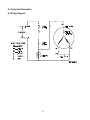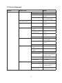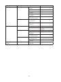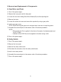
1
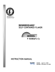
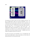
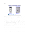
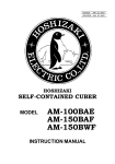
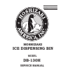
73128
NO:
ISSUED:
REVISED:
HOSHIZAKI
July 13, 2005
June 15, 2005
ICE DISPENSING BIN
MODEL
DB-130H
SERVICE MANUAL
IMPORTANT
Only qualified service technicians should attempt to service or maintain this
dispensing bin. No service or maintenance should be undertaken until the
technician has thoroughly read this Service Manual.
HOSHIZAKI provides this manual primarily to assist qualified service technicians in the
service and maintenance of the dispensing bin.
Should the reader have any questions or concerns which have not been satisfactorily
addressed, please call or write to the HOSHIZAKI Technical Support Department for
assistance.
HOSHIZAKI AMERICA, INC.
618 Highway 74 South
Peachtree City, GA 30269
Attn: HOSHIZAKI Technical Support Department
Phone: 1-800-233-1940 Technical Service
(770) 487-2331
Fax:
1-800-843-1056
(770) 487-3360
Web Site: www.hoshizakiamerica.com
Note: To expedite assistance, all correspondence/communication MUST include the
following information:
• Model Number
• Serial Number
• Complete and detailed explanation of the problem
2
Please review this manual. It should be read carefully before the dispensing bin
is serviced or maintenance operations are performed. Only qualified service
technicians should service and maintain the dispensing bin. This manual should be
made available to the technician prior to service or maintenance.
CONTENTS
I. Specification ....................................................................................................................... 4
II. General Information ........................................................................................................... 5
A. Construction .................................................................................................................. 5
III. Technical Information ........................................................................................................ 6
A. Wiring Diagram ............................................................................................................. 6
IV. Service Diagnosis ............................................................................................................. 7
V. Removal and Replacement of Components ..................................................................... 9
A. Gear Motor and Chain ................................................................................................. 9
B. Safety Switch ................................................................................................................ 9
C. Spout Switch ............................................................................................................... 10
D. Solenoid ...................................................................................................................... 10
VI. Cleaning and Maintenance Instructions ......................................................................... 11
A. Preparing the Ice Dispensing Bin for Long Storage .................................................... 11
B. Cleaning Instructions .................................................................................................. 11
1. Cleaning Procedure ............................................................................................... 11
2. Sanitizing Procedure – Following Cleaning Procedure.......................................... 13
C. Maintenance ............................................................................................................... 13
3
I. Specification
AC SUPPLY VOLTAGE
AMPERAGE
MINIMUM CIRCUIT AMPACITY
MAXIMUM FUSE SIZE
APPROXIMATE ELECTRIC CONSUMPTION
115/60/1
1.4 A
15 A
15 A
110 W
APPROXIMATE STORAGE CAPACITY
130 lbs (60 Kg)
APPROXIMATE ICE DISPENSING SPEED
20 lbs/min
EXTERIOR DIMENSIONS ( W x D x H )
INTERIOR DIMENSIONS ( W x D x H )
EXTERIOR FINISH
INTERIOR FINISH
INSULATION
WEIGHT
CONNECTIONS - ELECTRIC
- DRAIN
- WATER INLET
22" x 30" x 53"
(560 x 757 x 1346 mm) With 6" Legs
15.3" x 22.4" x 22.5"
(389 x 569.5 x 571 mm)
Plastic/SUS Front Cover, P.V.C Galvanized Steel Side Panels
Galvanized Steel Rear Panel
Polyethelene 1 pc. Mold
Polyurethane Foam
Net 178.4 lbs (81 kg), Shipping 220 lbs (100 kg)
Permanent Connection
Outlet 3/4" FPT
N/A
GEAR MOTOR
AGITATOR
60 W
Stainless Steel Round Bar 14.5" Dia.
GEAR MOTOR PROTECTION
SAFTEY PROTECTION
Thermal Protector (Internal)
Interlock Switch for Front Panel
Saftey Switch for Ice Spout
ACCESSORIES - OPTIONAL
6" Legs, 4 pcs
OPERATING CONDITIONS
VOLTAGE RANGE
AMBIENT TEMP.
(9 kg/min)
104 - 132 V
45 - 100° F
We reserve the right to make changes in specifications and design without prior notice.
4
II. General Information
A. Construction
5
III. Technical Information
A. Wiring Diagram
6
IV. Service Diagnosis
Problem
[1] No ice dispensed.
Possible Cause
a) Power Supply
Remedy
1. "OFF" position.
1. Move to "ON" position.
2. Loose connection.
2. Tighten.
3. Bad contacts.
3. Check for continuity and
replace.
4. Voltage too high.
4. Check and get
recommended voltage.
b) Fuse (Inside Fused
Disconnect, if any)
1. Blown.
1. Check for short circuit and
replace.
c) Spout Switch
1. Bad contacts.
1. Check for continuity and
replace.
2. Loose connection.
2. Tighten.
1. Front panel is not in
position.
1. Place in position.
d) Door Switch
2. Actuating plate does not 2. Check for continuity and
push door switch.
adjust.
e) Safety Switch
f) Gear Motor
g) Solenoid
3. Bad contacts.
3. Check for continuity and
replace.
4. Loose connection.
4. Tighten.
1. Spout is not in position.
1. Check for continuity and
place in position.
2. Bad contacts.
2. Check for continuity and
replace.
3. Loose connection.
3. Tighten.
1. Thermal protector is
tripped.
1. Allow to cool.
2. Gear motor winding
opened.
2. Replace.
3. Bearing worn out.
3. Replace.
4. Wiring to gear motor.
4. Check for loose connection
or open circuit, and replace
wiring as needed.
5. Defective capacitor.
5. Replace.
6. Agitator rotates in
reverse direction.
6. Check leads and reverse the
connections.
1. Solenoid winding open.
1. Replace
2. Wiring to solenoid.
2. Check for loose connection
or open circuit, and replace
wiring as needed.
3. Overload due to
loosening screws.
3. After tightening, apply
thread sealant to the parts.
7
Problem
Possible Cause
h) Mechanism
i) Ice Storage
[2] Abnormal noise.
1. Place in position or tighten.
2. Corrosion.
2. Apply oil.
3. Key of sprocket is not in
position.
3. Place in position.
4. Bad alignment of
sprocket.
4. Readjust.
5. Foreign matter
interrupting agitator.
5. Remove foreign matter.
1. No ice or little ice in
storage bin.
1. Make ice.
2. Ice bridge or block
formed.
2. Break with a poker.
a) Gear Motor or Gear Head 1. Bearing worn out.
b) Mechanism
c) Solenoid
[3] Ice in storage bin often
melts.
Remedy
1. Chain out of position or
loose.
a) Bin Drain
1. Replace.
2. Grease leaks.
2. Supply grease and replace
O-ring.
1. Bad setting.
1. Apply oil and readjust.
2. Bad alignment of
sprocket.
2. Readjust.
3. Foreign matter
interrupting agitator.
3. Remove foreign matter.
1. Overload due to
loosening screws.
1. After tightening, apply
thread sealant to the parts.
2. Foreign matter on
plunger.
2. Clean.
1. Foreign matter blocking
bin drain.
1. Remove foreign matter.
8
V. Removal and Replacement of Components
A. Gear Motor and Chain
1) Turn off the power supply.
2) Remove the front panel and left side panel.
3) Loosen the four bolts holding Gear Motor Bracket (B) and the adjusting bolt.
4) Remove the chain.
5) Loosen the socket set screw and remove the sprocket by using a gear puller.
6) Install a new gear motor.
NOTE: When removing the gear motor and gear head, take care to keep the grease.
7) Assemble the removed parts in the reverse order of the above procedure.
NOTE:
• When weight (2.2 Ib) is applied to the chain at the center, the displacement must
be 0.31 to 0.51".
• Lubricant (Class SAE 20) must be applied to the chain using a cloth.
8) Turn on the power supply.
B. Safety Switch
1) Turn off the power supply.
2) Remove the front panel.
3) Remove the safety switch cover.
4) Disconnect the connectors from the safety switch leads.
5) lnstall a new safety switch.
6) Assemble the removed parts in the reverse order of the above procedure.
7) Turn on the power supply.
9
C. Spout Switch
1) Turn off the power supply.
2) Remove the front panel.
3) Remove the spout switch assembly and Barrier (A).
4) Disconnect the connectors from the spout switch leads.
5) Install a new spout switch.
6) Assemble the removed parts in the reverse order of the above procedure.
7) Turn on the power supply.
D. Solenoid
1) Turn off the power supply.
2) Remove the front panel and the left side panel.
3) Disconnect the connectors from the solenoid leads, and remove the solenoid assembly.
4) Remove the solenoid, and install a new solenoid. Securing torque should be
13 to 17.3 in. lb.
5) Assemble the removed parts in the reverse order of the above procedure.
6) Turn on the power supply.
10
VI. Cleaning and Maintenance Instructions
IMPORTANT
Ensure all components, fasteners and thumbscrews are securely in place after
any maintenance or cleaning is done to the equipment.
A. Preparing the Ice Dispensing Bin for Long Storage
IMPORTANT
Drain the icemaker and remove all ice from the ice dispensing bin when
shutting off the icemaker/ice dispensing bin for storage. The ice dispensing bin
should be cleaned and wiped dry.
1) Shut off the icemaker. See the "Preparing the Icemaker for Long Storage" instructions on
the icemaker.
2) Turn off the power supply switches for both the icemaker and the ice dispensing bin after
removing all ice.
3) Clean the ice dispensing bin and wipe it dry.
B. Cleaning Instructions
WARNING
1. HOSHIZAKI recommends cleaning this unit at least once a year. (See the
"Cleaning Instructions" on the icemaker.) More frequent cleaning, however,
may be required in some existing water conditions.
2. To prevent injury to individuals and damage to the icemaker/ice dispensing
bin, do not use ammonia type cleaners.
3. Always wear liquid-proof gloves to prevent the cleaning and sanitizing
solutions from coming into contact with skin.
1. Cleaning Procedure
1) Clean and sanitize the ice dispensing bin/icemaker (see the cleaning instructions on the
icemaker) as conditions require.
2) Remove all ice from the bin.
3) Disconnect electrical power to the ice dispensing bin/icemaker.
4) Remove the drain gate and simply lift out the chute for cleaning.
5) Remove or reposition the icemaker to allow access to the inside. Be sure that the
icemaker is secured and cannot fall.
11
Spout – Front Panel
Chute
12
6) Scrub the inside of the bin, the agitator, the spout of the bin, the spout of the front panel
and chute using a nylon scouring pad, brushes and cleaning solution, such as 5 oz.
Hoshizaki “Scale Away” or “Lime-A-Way” (Economics Laboratories Inc.), in one gallon of
water.
7) Remove the shutter assembly and spout and scrub them using the cleaning solution
made in step 6. See the illustration on the previous page.
a) Remove the snap pin fitted to the shutter shaft and shift the shaft to
the right. Then the shutter assembly can be removed from the bin.
b) Pull out on the sides of the hook to release the spout. Lift the spout up and out from
the bin.
c) Remove the thumbscrews holding the hook and take it off the spout. Take off the
snap pin and the axle from Shutter (B). Open out Shutter (B) and remove the balance
weight.
8) Rinse all parts thoroughly with clean water.
2. Sanitizing Procedure – Following Cleaning Procedure
1) Wash all parts in steps 6) and 7) using the following sanitizing solution: 1/2 fl. oz. of a
5.25% sodium hypochlorite solution (chlorine bleach) diluted in 1 gallon of water.
2) Rinse all parts thoroughly with clean water.
3) Reassemble in the reverse order of the removal procedure.
4) Turn on the icemaker/ice dispensing bin.
5) Check for proper operation.
C. Maintenance
1) Exterior Panels
To prevent corrosion, wipe occasionally with a clean, soft cloth. Use a damp cloth
containing a neutral cleaner to wipe off oil or dirt build up.
2) In view of the simple design of this ice dispensing bin, and the limited operating time,
very little maintenance is required.
Inspect and oil the chain (2 or 3 drops) annually. Adjust as necessary for 3/8” to 1/2” free
play.
13