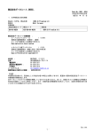
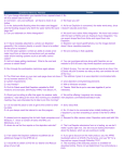
1
T8621A,C,D, CHRONOTHERM III
FUEL SAVER THERMOSTATS
APPLICATION
These thermostats provide energy saving control for a
24 Vac heating/cooling system as indicated in Table 1, and
are powered direct from the control transformer.
As long as thermostat is continuously powered, the
thermostat will be compatible with any control system.
These models include a SYSTEM LED, which is on
when the thermostat is signaling for heating or cooling. Heat
and cool anticipation is fixed in all models; no adjustment is
necessary. Cycle rates are adjustable for highest stage of
heating.
Fan operation option switch is included on SUPER
TRADELINE model to select fan operation for electric heat
application.
12/24 hour clock conversion and °C/°F conversion is
available on some models only.
TABLE 1—THERMOSTAT MODELS.
STAGES
THERMOSTAT
HEAT
COOL
T8621A
1
1
T8621C
2
1
T8621D
2
2
T8621Da
2
2
aSUPER TRADELINE model.
SWITCHING
SYSTEM
FAN
HEAT-AUTO-COOL-OFF ON-AUTO
HEAT-AUTO-COOL-OFF ON-AUTO
HEAT-AUTO-COOL-OFF ON-AUTO
HEAT-OFF-COOL
ON-AUTO
APPLICATION
Single Stage
Multistage
Multistage
Multistage
INSTALLATION
WHEN INSTALLING THIS PRODUCT…
1. Read these instructions carefully. Failure to follow
them could damage the product or cause a hazardous
condition.
2. Check the ratings on the product to make sure the
product is suitable for your application.
3. Installer must be a trained, experienced service technician.
4. Allow thermostat to warm to room temperature before
operating.
5. After installation is complete, check out product operation as provided in these instructions.
CAUTION
Disconnect power supply to prevent electrical shock
or equipment damage.
IMPORTANT
After wiring is complete, push excess wire back into
the hole, and plug hole with nonhardening caulk,
putty, or insulation to prevent drafts from affecting
thermostat operation.
LOCATION
Install thermostat and subbase about 5 ft. [1.5 m] above
the floor in an area with good air circulation at room
temperature.
Do not install the thermostat where it may be affected
by—
— drafts or dead spots behind doors, in corners, or
under cabinets.
— hot or cold air from ducts.
— radiant heat from sun or appliances.
— concealed pipes and chimneys.
— unheated (uncooled) areas behind the thermostat,
such as an outside wall.
IF REPLACING AN EXISTING THERMOSTAT
Turn power to thermostat off at furnace or boiler. A two
transformer system may require turning off two switches or
disconnects. Remove any existing wallplate or subbase
from wall. Label or write down each wire color with the letter
or number on the wiring terminal as the wire is removed, to
avoid miswiring later.
C. H.
Rev. 12-90
IF NEW INSTALLATION
Run cable to a hole at the selected wall location, and pull
about 3 in. [76 mm] of wire through the opening. Colorcoded, 18 gauge thermostat cable with one conductor for
each wiring terminal is recommended. Good service practice recommends selecting cable with one or two more
conductors than the immediate application requires.
MOUNTING SUBBASE
IMPORTANT
• The T8621 requires an additional conductor to
transformer common to provide continuous 24 V
power for thermostat operation.
• Set the system switch in the OFF position before
mounting the subbase.
The subbase does not require leveling for proper operation, but for appearance only.
Remove thermostat from subbase (Fig. 1).
The subbase mounts directly onto the wall with the
screws and anchors included in the package. If drywall
construction, plastic anchors must be used; use the subbase as a template, and with a pencil, mark the two
mounting screw positions (Fig. 2). Use 3/16 in. bit to drill
holes for anchors. Gently tap anchors into holes until they
are flush to the wall surface. Thread wires through the
center opening of the subbase. Then, mount the subbase
using two screws provided. Gently tighten screws, level top
surface of subbase, then securely tighten screws.
HEAT AUTO
COOL OFF
FAN
ON
AUTO
M844
Fig. 1—Removing thermostat from subbase.
Form Number 69-0330—3
©Honeywell Inc. 1990
Refer to Figs. 4-9 for typical hookups of subbase thermostat.
NOTE: Restrict all wiring to recessed area surrounding
terminals (Fig.3) to assure thermostat/subbase contact.
WALL
WIRES THROUGH
WALL OPENING
ADJUSTING CYCLE RATE
To custom-tailor the thermostat’s cycling performance
to different types of heating equipment, cycle rate adjustment screws are provided on the back of the thermostat.
Correct setting of these screws will provide optimum room
temperature control.
NOTE: MOST APPLICATIONS WILL NOT REQUIRE A
CHANGE IN CYCLE RATE.
WALL
ANCHORS
(2)
MOUNTING
HOLES
HEATING
TRANSFORMER
MOUNTING
SCREWS (2)
SUBBASE
R
M846
2
L2
3
HIGH
LIMIT
POWER
SUPPLY
Fig. 2—Mounting subbase on wall.
1
L1
(HOT)
C
H
HEAT RELAY
W1
SYSTEM
SWITCH
FOR STRAIGHT
INSERTION –
STRIP 5/16 in. (8 mm)
HEAT
AUTO
FOR WRAPAROUND –
STRIP 7/16 in. (11 mm)
RESTRICT
WIRING TO
THIS AREA
COOL
OFF
C
Y1
FRONT VIEW OF
TERMINAL AREA
FAN
SWITCH
COOLING
CONTACTOR
AUTO
KEEP WIRING BELOW
THIS SURFACE
G
TOP SURFACE
OF SUBBASE
ON
FAN RELAY
2
L1
(HOT)
RC
CROSS-SECTIONAL VIEW OF
TERMINAL AREA
COOLING
TRANSFORMER
M847
L2
1
1 POWER SUPPLY. PROVIDE DISCONNECT MEANS AND OVERLOAD
PROTECTION AS REQUIRED.
Fig. 3—Restrict wiring to recessed area surrounding
terminals.
2 FOR SINGLE TRANSFORMER SYSTEM JUMPER R AND RC.
WIRING
All wiring must comply with local electrical codes and
ordinances.
Disconnect power before wiring to prevent electrical
shock or equipment damage.
The shape of the terminal barrier permits insertion of
straight or conventional wraparound wiring connections.
Either method is acceptable.
Push excess wire back into the hole, and plug hole with
nonhardening caulk, putty or insulation to prevent drafts
from affecting thermostat operation.
3 NOMINAL 24 Vac POWER MUST BE PRESENT BETWEEN R AND C FOR
THERMOSTAT OPERATION.
M1574
Fig. 4—T8621A 1-stage heat/1-stage cool thermostat
with HEAT-AUTO-COOL-OFF system and
AUTO-ON fan switching.
2
HEATING
TRANSFORMER
R
2
POWER
SUPPLY
HIGH
LIMIT
SYSTEM
TRANSFORMER
C
H1
R
POWER
SUPPLY
HIGH
LIMIT
HEAT RELAY 1
W1
H2
L2
1
L2
3
HIGH
LIMIT
L1
(HOT)
1
L1
(HOT)
C
HIGH
LIMIT
HEAT RELAY 2
H1
W2
K
W1
SYSTEM
SWITCH
SYSTEM
SWITCH
HEAT
2
COOLING
CHANGEOVER
RELAY K
H2
HEAT
W2
AUTO
AUTO
COOL
COMPRESSOR
CONTACTOR
COOL
OFF
OFF
C2 3
C2
Y2
Y2
COOLING
CONTACTOR 2
C1
C1
Y1
Y1
FAN
SWITCH
FAN
SWITCH
AUTO
COOLING
CONTACTOR 1
AUTO
FAN RELAY
G
G
ON
ON
FAN RELAY
2
L1
(HOT)
RC
COOLING
TRANSFORMER
RC
L2
1
1 POWER SUPPLY. PROVIDE DISCONNECT MEANS AND OVERLOAD
PROTECTION AS REQUIRED.
2 FOR SINGLE TRANSFORMER SYSTEM JUMPER R AND RC.
1
POWER SUPPLY. PROVIDE DISCONNECT MEANS AND OVERLOAD
PROTECTION AS REQUIRED.
2
ADD RELAY (SPDT) TO ACCOMMODATE COOLING CHANGEOVER.
3
T8621D ONLY.
NOTE: SET CYCLE RATE TO HOT WATER SETTING (3 cph).
THERMOSTAT DOES NOT PROVIDE MINIMUM OFF TIME
IN HEATING.
M1575
3 NOMINAL 24 Vac POWER MUST BE PRESENT BETWEEN R AND C FOR
THERMOSTAT OPERATION.
M1573
Fig. 5—T8621C,D 2-stage heat/2-stage cool thermostat
with HEAT-AUTO-COOL-OFF system and
AUTO-ON fan switching. For T8621C, delete
second cooling stage.
Fig. 6—T8621C,D single-stage heat pump thermostats
with cooling changeover. HEAT-AUTO-COOLOFF system and AUTO-ON fan switching.
3
69-0330—3
L1
(HOT) L2
1
HEATING
TRANSFORMER
R
L1
(HOT)
4
L2
1
FAN
OPERATION
SWITCH
R
POWER
SUPPLY
HIGH
LIMIT
POWER
SUPPLY
HIGH
LIMIT
SYSTEM
TRANSFORMER
C
HIGH
LIMIT
W1
3
ELECTRIC
C
HIGH
LIMIT
HEATING
CHANGEOVER
H1
W2
HEAT 2
SYSTEM
SWITCH
W1
STAGE 1
HEAT RELAY
HEAT 1
NON- 2
ELECTRIC
STAGE 2
HEAT RELAY
HEAT
B
SYSTEM
SWITCH
COMPRESSOR
CONTACTOR
H2
HEAT
OFF
HEATING DAMPER OR
CHANGEOVER RELAY
COOL
W2
COOLING DAMPER OR
CHANGEOVER RELAY
AUTO
COOL
O
OFF
C2
2
STAGE 2
COOLING RELAY
Y2
Y2
COOL 1
COOL 2
C1
STAGE 1
COOLING RELAY
Y1
Y1
FAN
SWITCH
AUTO
FAN
SWITCH
FAN RELAY
FAN RELAY
G
AUTO
ON
G
ON
3
RC
RC
1
2
POWER SUPPLY. PROVIDE DISCONNECT MEANS AND OVERLOAD
PROTECTION AS REQUIRED.
COOLING
TRANSFORMER
T8621D ONLY.
1
NOTE: SET CYCLE RATE TO HOT WATER SETTING (3 cph).
THERMOSTAT DOES NOT PROVIDE MINIMUM OFF TIME
IN HEATING.
M1576
Fig. 7—T8621C,D single-stage heat pump thermostats
with heating changeover. HEAT-AUTO-COOLOFF system and AUTO-ON fan switching.
L1 L2
(HOT)
1
POWER SUPPLY. PROVIDE DISCONNECT MEANS
AND OVERLOAD PROTECTION AS REQUIRED.
2
FOR GAS OR OIL APPLICATIONS OR ELECTRIC HEAT
APPLICATIONS WHERE THE FAN OPERATION IS CONTROLLED
INDEPENDENTLY OF THE THERMOSTAT (AUTO FAN OPERATES
WITH Y1 ONLY). TWO TRANSFORMERS MAY BE USED. SET
SWITCH TO NONELECTRIC POSITION.
3
FOR ELECTRIC HEAT APPLICATIONS (AUTO FAN OPERATES
WITH W1 AND Y1), USE ONLY ONE TRANSFORMER; JUMPER
R AND RC. SET SWITCH TO ELECTRIC POSITION.
4
NOMINAL 24 VAC POWER MUST BE PRESENT BETWEEN
R AND C FOR THERMOSTAT OPERATION.
M13444
Fig. 8—T8621D 2-stage heat/2-stage cool manual
changeover thermostat with auto fan on heat
and cool; convertible to auto fan on cool only.
HEAT-OFF-COOL system and AUTO-ON fan
switching.
4
L1
(HOT)
FAN OPERATION OPTION SWITCH
The SUPER TRADELINE model includes a fan operation option switch on the subbase, visible before the thermostat is mounted on the subbase. The switch should be in
electric heat position for electric heating systems that do not
have independent fan control.
L2
1
SYSTEM
TRANSFORMER
INSTALLING BATTERIES
Three AAA alkaline batteries are provided as backup to
prevent program loss in case of power outage. Batteries are
included with thermostat. Install batteries in back of thermostat as shown in Fig. 11.
Without battery backup, the program will remain about
30 seconds in event of power loss.
R
3
HIGH
LIMIT
FAN
OPERATION
SWITCH
2
POWER
SUPPLY
C
HIGH
LIMIT
IMPORTANT
When batteries are first installed, the display will flash
1:00 PM and 32° or 0°. The temperature display will
stay at 32° or 0° until the thermostat is powered from
the system wiring.
W1
ELECTRIC
HEAT 1
NON-ELECTRIC
W2
HEAT 2
SYSTEM
SWITCH
HEATING
CHANGEOVER
RELAY
HEAT
B
OFF
COOL
COOLING
CHANGEOVER
RELAY
O
1A 1B
COOL 1
1
2A 2B
Y2
COOL 2
COMPRESSOR
CONTACTOR
Y1
FAN
SWITCH
FAN RELAY
AUTO
SYSTEM
G
ON
HOT
WATER
GAS/OIL
WARM AIR
RC
1
1A
ELECTRIC
WARM AIR
POWER SUPPLY. PROVIDE DISCONNECT MEANS AND
OVERLOAD PROTECTION AS REQUIRED.
2 FAN OPERATION SWITCH MAY BE IN EITHER POSITION.
1
3 NOMINAL 24 VAC POWER MUST BE PRESENT BETWEEN R AND C
FOR THERMOSTAT OPERATION.
M1546A
CYCLES
PER HOUR
TIME/TEMP
DISPLAY
OUT 1/2
TO 1 TURN
1
24 HR
IN
3
12 HR
6
oC
9
o
1B
OUT 1/2
GRAVITY
AIR/WATER TO 1 TURN
OUT 1/2
TO 1 TURN
IN
IN
(FACTORY SETTING)
IN
OUT 1/2
TO 1 TURN
2B
2A
IN
OUT 1/2
TO 1 TURN
IN
OUT 1/2
TO 1 TURN
F
SCREWS 2A, 2B ONLY AVAILABLE ON SOME MODELS.
M311A
Fig. 10—Cycle rate adjustment.
Fig. 9—T8621D single-stage manual changeover heat
pump thermostat. HEAT-OFF-COOL system
and AUTO-ON fan switching.
The room air temperature will normally vary slightly from
the comfort temperature setting with the cycling of the
furnace or air conditioner.
The heating cycle rate of this thermostat is factory-set for
gas/oil warm air heating. The cooling cycle rate cannot be
adjusted. The heating cycle rate can be adjusted by turning
one or both cycle rate adjustment screws located on the
back of the thermostat. In multistage heat systems, the
cycle rate adjustment applies to stage 2 only; stage 1 is
fixed. See Fig. 10.
BATTERY PLACEMENT
(NOTE CORRECT PLUS
AND MINUS DIRECTION) M372A
TIME/TEMPERATURE CONVERSION (SOME MODELS)
The display readout may be converted between 12 and
24 hour clock or °C and °F using screws 2A and 2B as
indicated in Fig. 10.
Fig. 11—Battery placement.
5
69-0330—3
When the batteries are low, the display will flash
REPL BAT. The building owner will have 20-30 seconds to
install new batteries after removing old batteries from
thermostat. After 20-30 seconds, it will be necessary to
reprogram. REPL BAT indication will disappear when thermostat is mounted back on the subbase.
If batteries are completely dead, the display will go
blank. After replacing the battery in this case, reprogramming will be necessary.
the display on during most power outages. Once the power
is restored, the system will resume normal operation.
If the display goes off when power is lost, either the
backup batteries need to be replaced or are not installed.
When power is restored, the display will flash 1:00 PM to
remind you to reprogram.
MOUNTING THE THERMOSTAT
Hang the thermostat on the tabs at the top of the base
(Fig. 12a). Swing down and press on lower edge until
thermostat snaps in place (Fig. 12b). Open cover, and
tighten the captive mounting screws (Fig. 12c).
POWER OUTAGES
Backup batteries will hold the programming and keep
A.
B.
SYSTEM
AM
MON
MORNIMG
ROOM
HEAT ON
FAN
AUTO
ON AUTO
COOL OFF
HEAT AUTO
C.
SYSTEM
AM
ROOM
HEAT ON
MON
MORNIMG
TEMPERATURE
PRESENT
SETTING
RUN
PROGRAM
TIME
SET
PRESENT
DAY/TIME
DAY
PERIOD
COPY
FROM
HOLD
TEMP
SET
HEAT/COOL
CANCEL
PERIOD
COPY
TO
AHEAD
WARMER
BACK
COOLER
SKIP
NEXT
PERIOD
CHANGE
TO LAST
PERIOD
M843
Fig. 12—Mounting thermostat on subbase.
SETTING DAY AND TIME
Restore 24 V power to the thermostat. When power is
applied to the thermostat, the display will read 1:00 PM and
room temperature. It will go off for a few seconds, then begin
to flash on and off. Set present day and time.
If the display will not come on—
— check mounting of thermostat to subbase. If loose or
misaligned, remove thermostat and reinstall on the
subbase, making sure it is firmly attached.
— check to see that heat or cool system power is on.
— check voltage between R and C; should be 24 to 30
Vac.
SET
Press
PRESENT
DAY/TIME
.
Press DAY
to set the current day. Each press of the
DAY key advances the display one day.
Press TIME
AHEAD
or
BACK
to set the current time.
CHECKOUT
HEATING
NOTE: When heating setting is changed, thermostat will
wait up to 5 minutes before turning on the heating
equipment. This delay protects the compressor.
delay on gas or oil forced air systems). Press COOLER key
until the setting is about 10° F [6° C] below room temperature. The heating equipment should shut off, followed by the
fan.
Move the system switch to HEAT and the fan switch to
AUTO. Press WARMER key until the setting is about 10° F
[6° C] above room temperature. Heating should start (both
stages if multistage), and the fan should run (may be a short
NOTE: On an AUTO changeover thermostat, the cooling
temperature must be set at least 3° F [2° C] above the
heating temperature, or display will flash.
6
COOLING
SYSTEM
SWITCH
POSITION
OFF
CAUTION
Do not operate cooling if outdoor temperature is
below 50° F [10° C]. Refer to manufacturer’s recommendations.
PRESS
THIS
KEY
CHANGE
TO LAST
LOOK FOR THIS RESPONSE
KEY
KEY
DOWN RELEASED
03
Blank
PERIOD
SKIP
NEXT
NOTE: When cooling setting is changed, thermostat will
wait up to 5 minutes before turning on the cooling
equipment. This delay protects the compressor.
07
Blank
15
Blank
15
1st stage cooling,
fan and SYSTEM
LED on.
2nd stage cooling
also on.
2nd stage cooling off.
PERIOD
PRESENT
SETTING
COOL or
AUTO (with
fan in AUTO)
Move the system switch to COOL and the fan switch to
AUTO. Press COOLER key until the setting is about 10° F
[6° C] below room temperature. The cooling equipment and
fan should start. Press WARMER key until the setting is
about 10° F [6° C] above room temperature. The cooling
equipment and fan should stop.
PRESENT
SETTING
PRESENT
SETTING
PRESENT
SETTING
NOTE: On an AUTO changeover thermostat, the heating
temperature must be set at least 3° F [2° C] below the
cooling temperature, or display will flash.
15
15
1st stage cooling, fan
and SYSTEM LED off.
NOTE: If single-stage cooling system, press key twice
instead of 4 times; once to turn cooling, fan and SYSTEM LED on, second time to turn off.
PRESENT
SETTING
FAN
Move the system switch to OFF, and the fan switch to
ON. The fan should run continuously. When the fan switch
is in the AUTO position, fan operates directly with the
cooling system, and also with heating system on some
models.
OFF
15
06
Blank
02
Blank
05
Blank
BACK
04
Blank
COPY
01
Blank
00
Blank
12
See note A
08
Blank
13
09
Microprocessor mask
no. and revision no.
Blank
14
Blank
14
1st stage heating and
SYSTEM LED on.
2nd stage heating
also on.
2nd stage heating off.
WARMER
COOLER
AHEAD
INSTALLER SELF-TEST (optional)
IMPORTANT
• AC power must be present on thermostat to conduct self-test. Relays will not toggle, codes will not
be present and thermostat will not manually exit
self-test without ac power.
FROM
COPY
TO
• Five-minute time delay on cooling does not function during self-test.
(CHECK
EACH
POSITION)
OFF
Perform the following test as a check of all thermostat
functions. If thermostat does not respond as indicated,
thermostat must be replaced.
1. Press AHEAD and BACK keys at the same time.
While holding keys down, all segments of the display should
be on (Fig. 13).
PERIOD
CANCEL
PERIOD
DAY
SET
HEAT/COOL
SET
PRESENT
DAY/TIME
AM
PM
REPL
HEAT or
AUTO 1
SET
PT
BAT
ROOM
SUN MON TUE WED THU FRI SAT TEMPORARY OUTDOOR
MORNING MIDDAY EVENING NIGHT COOL ON HEAT ON
SET
PRESENT
DAY/TIME
SET
PRESENT
DAY/TIME
SET
PRESENT
DAY/TIME
M525A
14
14
1st stage heating and
SYSTEM LED off.
NOTE: If single-stage heating system, press key twice
instead of 4 times; once to turn heating and SYSTEM
LED on, second time to turn off.
SET
PRESENT
DAY/TIME
Fig. 13—All segments on display.
2. Set system switch to OFF. Press AHEAD and BACK
and PRESENT SETTING keys at the same time to enter
self-test.
OFF
3. Press each key as listed below, and look for response
listed as key is held down and released.
HOLD
TEMP
14
10
Blank
Normal operating
display.
For electric heat fan operation—The fan will operate
with the heating system when fan switch is in AUTO.
HEAT displayed when system switch is in HEAT,
COOL when in COOL, HEAT and COOL when in
AUTO, neither when in OFF. Also, a four-digit code is
displayed, with each digit explained below.
RUN
11
PROGRAM
1
A
7
69-0330—3
FIRST
DIGIT
0
1
2
3
CYCLE RATE SETTING
(CPH at 50% on time for
stage 1 on 1-heat models,
stage 2 on 2-heat models)
1
3
9
6
THIRD
DIGIT
0
1
3
4
5
MANUAL OR AUTO
CHANGEOVER
Manual
Auto
Auto
Manual
Auto
SYSTEM
SWITCH
POSITION
HEAT or OFF
HEAT or OFF
AUTO
COOL
COOL
M13443
SECOND
DIGIT
0
1
2
3
4
5
6
STAGES OF
HEAT
COOL
2
1
2
2
1
1
1
2
0
2
1
0
2
0
FOURTH
DIGIT
0
DEGREES
F
CLOCK
(HRS)
12
1
F
24
2
3
4
F
F
C
12
24
12
5
C
24
6
7
C
C
12
24
SYSTEM
SWITCH
POSITION
COOL, AUTO
or OFF
COOL, AUTO
or OFF
HEAT
HEAT
COOL, AUTO
or OFF
COOL, AUTO
or OFF
HEAT
HEAT
This equipment is a Class B digital apparatus which complies with Canadian Radio Interference Regulations, CRC c. 1374.
Honeywell Inc.
U.S.A.: 1885 Douglas Drive N.
Golden Valley, MN 55422-4386
CANADA: 740 Ellesmere Road
Scarborough, Ontario M1P 2V9
International Sales Offices in all principal cities of the world. Manufacturing in
Australia, Canada, Finland, France, Germany, Japan, Mexico, Netherlands,
Spain, Taiwan, United Kingdom, U.S.A.
PRINTED IN TAIWAN R.O.C.
QUALITY IS KEY