1
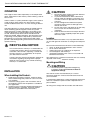
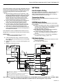
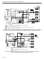
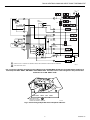
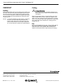
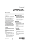
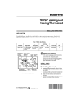
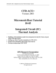
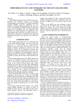
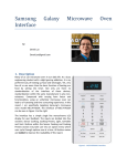
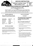
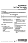
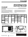
T841A Heating-Cooling
Heat Pump Thermostat
INSTALLATION INSTRUCTIONS
APPLICATION
The T841A Heating-Cooling TRADELINE® Thermostat
provides 24 Vac control of two-stage heating and onestage cooling in heat pump systems, using manual
changeover. This thermostat provides SYSTEM switch
selections of EM. HEAT-HEAT-OFF-COOL and FAN
switch selections of AUTO-ON. See Fig. 1. See Table 1 for
T841A TRADELINE® specifications.
Test holes are provided on the front of the thermostat to
accommodate test meter probes without removing the
thermostat from the wall. Remove the cover of the
thermostat to expose the test holes, which are labeled to
correspond with the terminals on the back of the
thermostat.
Table 1. T841A TRADELINE® Specifications.
OS Number
T841A1308
LED
Indication
EM. HEATa,
AUX. HEAT
Changeover
Manual Cool
or Heat
T841A1316
T841A1423b
T841A1464b,c
T841A1498
Heat
Anticipation
Stage 2 fixed,
0 to 1.5A
Terminal
Designations
G, R, W2, E,
L, B, X, Y, O
G, R, E, L, X
W 2, B, W1,
Y1, O
Stage 2
W 3, G, R, W2,
adjustable, 0.1 E, L, B, X, Y,
to 1.2A
O
EM. HEAT,
AUX. HEAT,
CHECKd
EM. HEAT
Stage 2 fixed,
0 to 1.5A
G, R, W, H, B,
X, O, Y
Remarks
Use when E
and W2 are
jumpered.
Does not
replace
T841A1068.
Not for systems
with E to W 2
jumper
System
Switch
EM. HEAT,
HEAT, OFF,
COOL
Auto Fan
in EM.
HEAT
No
Yes
Exact
replacement for
York model no.
2TH11703324
T841A1506b
a
b
c
d
EM. HEAT LED also indicates compressor malfunction.
Premier White® color.
Sold only in Australia: degrees C.
CHECK LED indicates compressor malfunction.
FRONT OF DEVICE
BACK OF DEVICE
COVER
80
80
70
60
50
70
60
THERMOMETER
50
SET POINT
SCALE
EM. HEAT HEAT OFF COOL
CHECK
FAN
AUTO
ON
EM. HEAT AUX. HEAT
SYSTEM SWITCH
FAN SWITCH
LED (UP
TO THREE)
MOUNTING
HOLES (4)
WIRING TERMINAL
(UP TO 12)
M2960A
Fig. 1. External view of T841A.
®U.S. Registered Trademark
Copyright © 1997 Honeywell Inc. •
• All Rights Reserved
X-XX UL
69-0452-8
T841A HEATING-COOLING HEAT PUMP THERMOSTAT
OPERATION
CAUTION
1.
The stages of heat make sequentially as the temperature
drops. Make refers to the mercury switch initiating a call for
heat or cool.
2.
There is about 1°F (0.6°C) between stages so the second
stage (auxiliary heat) makes only when the first stage
cannot handle the load. This 1°F is the interstage differential.
3.
4.
The LED indicators on certain thermostat models light up
when something specific happens within the system.
When the green or amber LED lights, the auxiliary heat
(second stage heat) is operating because the weather is
so cold, the heat pump alone cannot handle the load.
When the red EM. HEAT LED lights, the emergency heat
is operating (usually electric strip heaters), because the
homeowner has physically switched to the EM. HEAT
position. See heating/cooling manufacturer instructions for
specific meaning.
5.
Disconnect power supply to prevent electrical
shock or equipment damage.
To prevent interference with the thermostat
linkage, keep wire length to a minimum and
run wires as close as possible to the thermostat base.
Do not overtighten the thermostat captive
mounting screws, because damage to the
threads can result.
Do not short across coil terminals on the relay.
This can burn out the thermostat heat
anticipator.
Never install more than one wire per terminal
unless a factory-supplied jumper with spade
terminal is used.
Location
Locate the thermostat about 5 ft (1.5m) above the floor in
an area with good air circulation at average room temperature.
RECYCLING NOTICE
Do not mount the thermostat where it can be affected by:
— drafts, or dead spots behind doors and in corners.
— hot or cold air from ducts.
— radiant heat from sun, appliances or fireplaces.
— concealed pipes and chimneys.
— unheated (uncooled) areas such as an outside wall
behind the thermostat.
This control contains mercury in a sealed tube. Do
not place the control in the trash at the end of its
useful life. If this control is replacing a control that
contains mercury in a sealed tube, do not place
your old control in the trash.
This thermostat is a precision instrument and was carefully
adjusted at the factory. Handle it carefully.
Contact your local waste management authority for
instructions regarding recycling and the proper
disposal of this control, or any control containing
mercury in a sealed tube.
Mounting and Wiring
CAUTION
Disconnect power supply before beginning
installation. Can cause electrical shock or
equipment damage.
INSTALLATION
The T841A can be mounted directly to a wall or
horizontal outlet box. Choose the method that best fits
your installation.
When Installing this Product…
1. Read these instructions carefully. Failure to follow
them could damage the product or cause a hazardous condition.
2. Check the ratings given in the instructions and on
the product to make sure the product is suitable for
your application.
3. Installer must be a trained, experienced technician.
4. After installation is complete, check out product
operation as provided in these instructions.
69-0452—8
In replacement applications, check the existing thermostat
wires for cracked or frayed insulation. Replace wires in
poor condition.
All wiring must comply with local codes and ordinances.
2
T841A HEATING-COOLING HEAT PUMP THERMOSTAT
SETTINGS
Grasp the thermostat cover at the top and bottom with one
hand. Pull outward on the bottom edge of the cover until it
snaps free of the thermostat base. Carefully remove and
save the packing material surrounding the mercury
switches.
1. Run the wiring (if necessary) to the location. If the
wiring is plastered into the wall, make a hole next to
the cable and loosen the wires so that they can be
pushed back into the wall later. Thread the wires
through the hole in the packing material saved
above. Connect the wires to the terminals on the
back of the thermostat. See Fig. 2 through 5.
2. Set the second stage adjustable heat anticipator to
match the current draw of the primary heating
control (see Heat Anticipator Setting section).
3. Push the excess wire back through the hole and
plug any opening with packing material to prevent
drafts that may affect thermostat performance.
4. Use screws to loosely secure the thermostat to the
wall or outlet box through the two mounting holes in
the middle of the device.
Heat Anticipator Setting
The second stage heat anticipator is adjustable. Move the
adjustable indicator to match the current draw of the
second stage heating primary control, or the anticipator
setting of the old thermostat. See Fig. 6.
Temperature Setting
Move the setpoint lever to the desired control point on the
temperature scale.
SYSTEM Switch Setting
The SYSTEM switch positions control the system operation as follows:
EM. HEAT: Emergency heat relay is energized. Cooling
system is off. Compressor is de-energized. Fan runs
on call for heat if FAN switch is in the AUTO
position. EM. HEAT LED is on.
HEAT: Heating system is automatically controlled by
the thermostat. Cooling system is off.
OFF: Both the heating and cooling systems are off. If
the fan is at the AUTO position, the cooling fan is
also off.
COOL: Cooling system is automatically controlled by
the thermostat. Heating system is off.
The sheetmetal screws included with the thermostat are
designed for use in plaster walls that do not need anchors.
IMPORTANT
An incorrectly leveled thermostat causes
inaccurate temperature control.
FAN Switch Setting
5. Level the thermostat using a spirit level or plumb
line. Tighten the two mounting screws at the middle
of the device.
6. Install the two screws in the top mounting holes and
tighten.
7. Replace the thermostat cover.
AUTO: Fan operates in response to thermostat in both
heating and cooling.
ON: Fan operates continuously.
L1
(HOT)
L2
ODT 1
RTD 1
H1
C1
FALL
H1 & C1
ANTICIPATOR
EHR 1
1
RTD 2
ODT 2
FAN
SWITCH
ERH 2
RTD 3
FAN RELAY
AUTO
G
ON
R
SYSTEM
MONITOR
H2 ANTICIPATOR
RTD 1
W2
AUX. HT.
LED (GREEN)
E
SYSTEM
SWITCH
H2
RD
EM. HEAT
RELAY
L
EM. HEAT
FALL
HEAT
B
OFF
EM. HT.
LED
2
(RED)
COOL
CHANGEOVER
RELAY (HEAT)
X
3
LACO
COMPRESSOR
CONTACTOR
CHP
Y
1
POWER SUPPLY. PROVIDE DISCONNECT MEANS AND OVERLOAD
PROTECTION AS REQUIRED.
2
WHEN SYSTEM MONITOR IS CONNECTED TO L TERMINAL, EM. HT.
LED ALSO INDICATES COMPRESSOR MALFUNCTION.
3
X TERMINAL MUST BE CONNECTED FOR PROPER OPERATION.
CHANGEOVER
RELAY (COOL)
O
M1099B
Fig. 2. Internal schematic and typical wiring diagram for TRADELINE® T841A1308 with EM. HEAT and AUX. HEAT
LEDs. No fan control in EM. HEAT. Provides heat or cool changeover relay control.
3
69-0452—8
T841A HEATING-COOLING HEAT PUMP THERMOSTAT
L1
(HOT) L2
1
CHANGEOVER
RELAY (COOL)
O
L
FALL
H1
FAN SWITCH
C1
EM. HT.
LED (RED)
AUTO
SYSTEM
MONITOR
3
FAN RELAY
G
H1 ANTICIPATOR
ON
R
C1 ANTICIPATOR
E
4
EM. HT.
RELAY
X
AUX. HT.
LED (GREEN)
W2
SYSTEM
SWITCH
FALL
AUX. HT.
RELAY
B
EM. HT.
H2
CHANGEOVER
RELAY (HEAT)
HEAT
W1
2
OFF
JUMPER
HEAT RELAY 1
Y1
COOL
H2 ANTICIPATOR
COMPRESSOR
CONTACTOR
1
POWER SUPPLY. PROVIDE DISCONNECT MEANS AND OVERLOAD PROTECTION AS REQUIRED.
2
REMOVE W1-Y1 JUMPER WHEN HEAT RELAY 1 IS USED.
3
WHEN L TERMINAL IS CONNECTED TO SYSTEM MONITOR, EM. HEAT LED ALSO INDICATES COMPRESSOR MALFUNCTION.
4
X TERMINAL MUST BE CONNECTED FOR PROPER OPERATION.
M1103E
Fig. 3. Internal schematic and typical wiring diagram for SUPER TRADELINE® T841A1316 with AUX. HEAT and
EM. HEAT LEDs. Provides heat or cool changeover relay control and automatic fan in EM. HEAT mode.
AUTO
G
ON
FAN
SWITCH
FALL
H1
C1
R
H1/C1
ANTICIPATOR
FAN RELAY
L1
(HOT)
L2
W
1
HEAT RELAY
H
"H" RELAY
2
B
EM. HT.
LED (RED)
SYSTEM
SWITCH
H2
ANTICIPATOR
3
X
EM. HT. RELAY
EM. HT.
HEAT
O
OFF
FALL
CHANGEOVER
RELAY (COOL)
COOL
H2
Y
1
POWER SUPPLY. PROVIDE DISCONNECT MEANS AND
OVERLOAD PROTECTION AS REQUIRED.
2
B TERMINAL MUST BE CONNECTED FOR PROPER OPERATION.
3
AUTO FAN IN EM. HEAT.
COMPRESSOR
CONTACTOR
M3171B
Fig. 4. Internal schematic and typical wiring diagram for TRADELINE® T841A1498 and T841A1506
with EM. HEAT LED. Provides cooling changeover relay control.
69-0452—8
4
T841A HEATING-COOLING HEAT PUMP THERMOSTAT
L1
L2
(HOT)
1
ODT 1
RTD 1
W3
8
EHR 1
RDT 2
FAN
SWITCH
H1
C1
RD
FALL
ODT 2
AUTO
5
ON
H1/C1
ANTICIPATOR
EHR 2
9
RTD 3
G
3
FAN REALY
R
W2
AUX. HT.
LED (GREEN)
4
12
RTD 1
E
EM. HT.
LED (RED)
EM. HT. RELAY
11
H2
FALL
2
L
SYSTEM
SWITCH
CHECK
LED (RED)
10
SYSTEM MONITOR
EM. HT.
B
6
HEAT
HEAT CHANGEOVER VALVE
OFF
X
COOL
CHP
LACO
Y
COMPRESSOR
CONTACTOR
O
1
POWER SUPPLY. PROVIDE DISCONNECT MEANS AND OVERLOAD PROTECTION AS REQUIRED.
2
AUTO FAN IN EM. HEAT.
COOL CHANGEOVER VALVE
M6059C
.1
2
.10
Fig. 5. Internal schematic and typical wiring diagram for TRADELINE® T841A1423 and T841A1464 (sold only in
Australia) with AUX. HEAT, EM. HEAT and CHECK LEDs. Provides heat or cool changeover relay control and
automatic fan in EM. HEAT mode.
5
LONGER
.1
1.2 .8.6 .4 .3
.2
EM.HEAT HEAT OFF COOL
MOVE INDICATOR
TO MATCH CURRENT
RATING OF PRIMARY CONTROL
M2962B
Fig. 6. Second stage adjustable heat anticipator indicator.
5
69-0452—8
T841A HEATING-COOLING HEAT PUMP THERMOSTAT
Cooling
CHECKOUT
CAUTION
Heating
Move the SYSTEM switch on the thermostat to HEAT and
the FAN switch to AUTO. Move the setpoint lever to about
10°F (6°C) above the room temperature. Heating should
start and the fan should run. Move the setpoint lever about
10°F (6°C) below the room temperature. Heating and fan
should shut off.
Do not operate cooling if outdoor temperature is
below 50°F (10°C). Refer to manufacturer recommendations.
Move the SYSTEM switch on the thermostat to COOL
and the FAN switch to AUTO. Move the setpoint lever
about 10°F (6°C) below the room temperature. Cooling
and fan should start. Move the setpoint lever about 10°F
(6°C) above the room temperature. Cooling and fan
should shut off.
NOTE: To prevent compressor short cycling, a minimumoff timer may be included to prevent the compressor from starting for up to five minutes from
when the thermostat last turned the compressor
off, or from when the system first received power.
Fan
Move the SYSTEM switch to OFF, and the FAN switch to
ON. The fan should run continuously. Move the FAN
switch to AUTO. In this position, the fan operates in
response to the thermostat in both heating and cooling.
Automation and Control Solutions
Honeywell Limited-Honeywell Limitée
Honeywell International Inc.
35 Dynamic Drive
1985 Douglas Drive North
Scarborough, Ontario M1V 4Z9
Golden Valley, MN 55422
69-0452—8 J.S. Rev. 5-97
6
www.honeywell.com/yourhome