1
TOAD -1 System
Installation and Operation Manual
for TOPS{20
SYSTEMS CORPORATION
special purpose computer design, manufacturing, and sales
8420 154th Avenue NE
Redmond, Washington 98052
(206) 869-9050
FAX: (206) 861-7863
DISCLAIMER
This draft document is still changing. As of the date of publication below, the information
included matches the way the system operates. Subsequent changes may invalidate parts
of this manual.
All material contained herein is proprietary to XKL Systems Corporation.
Part Number 50103{00002
November 22, 1996
Copyright c 1995, 1996 XKL Systems Corporation.
This document contains information which is protected by copyright. All rights are reserved. Reproduction, adaptation, or translation without prior written permission is prohibited, except as allowed
under the copyright laws.
Restricted Rights Legend. Use, duplication, or disclosure by the United States Government
is subject to restrictions as set forth in subparagraph (c)(1)(ii) of the Rights in Technical Data
and Computer Software clause at DFARS 252.227{7013 for Department of Defense agencies, and
subparagraphs (c)(1) and (c)(2) of the Commercial Computer Software Restricted Rights clause at
FAR 52.227{19 for other agencies.
Use of this manual and any software supplied with it is restricted to this product only. Additional
copies of the programs may be made for security and back{up purposes only. Resale of the programs,
in their present form or with alterations, is expressly prohibited.
Warranty
The information in this publication is subject to change without notice. The
information contained herein should not be construed as a commitment by
XKL Systems Corporation.
XKL Systems Corporation makes no warranty of any kind with
regard to this material, including, but not limited to, the implied
warranties of merchantability and tness for a particular purpose.
XKL Systems Corporation shall not be liable for errors contained herein or
for incidental or consequential damages in connection with the furnishing,
performance, or use of this material.
This document may contain material previously published by Digital Equipment Corporation. Any
such material is used here under license from Digital Equipment Corporation.
The following are trademarks of Digital Equipment Corporation: CI, DEC, DECnet, DECUS,
DECsystem{10, DECSYSTEM{20, DDT, HSC, HSC{50, MASSBUS, PDP, PDP{10, TOPS{10,
TOPS{20, TOPS{20AN, UETP, and d i g i t a l
National Electrical Code and NEC are registered trademarks of the National Fire Protection Association
PostScript is a trademark of Adobe Systems Incorporated. UNIX is a trademark of some organization, probably Novell.
iii
Notice:
The TOAD -1 System has been tested and found to comply with the limits for
a Class A digital device, pursuant to part 15 of the (U.S.) FCC Rules. These
limits are designed to provide reasonable protection against harmful interference
when the equipment is operated in a commercial environment. This equipment
generates, uses, and can radiate radio frequency energy and, if not installed and
used in accordance with the instructional manual, may cause harmful interference
to radio communications. Operation of this equipment in a residential area is likely
to cause harmful interference in which case the user will be required to correct the
interference at his own expense.
iv
v
Preface
The TOAD -1 System Installation and Operation Manual for TOPS{20 describes the procedures for
installing a new TOAD -1 System and customizing it to a particular network environment. This
manual also briey describes how to manage and operate the system, including such topics as
generating tailored Galaxy software.
In several places in this document, nouns (e.g., boot) are used as verbs and vice versa. This is done
for conciseness at the expense of Standard English usage. We apologize in advance to any oended
readers.
Audience
This manual addresses TOPS{20 operators, system managers, and others who have the responsibility
to:
Install the new TOAD-1 System and customize the software for the particular TCP/IP envi
ronment found at the site.
Test the success of the installation.
Manage and operate the system.
Generate a tailored batch and spooling (Galaxy) system.
Organization
Chapter 1
Site Preparation describes the physical environment necessary to support the
Chapter 2
Physical Setup explains how to unpack the TOAD-1 System and connect it to the
Chapter 3
Chapter 4
TOAD -1 System.
surrounding environment. This chapter also describes the indicator lamps found on
the system and on the individual circuit boards.
Initial Boot describes the procedure for booting the system the rst time. This
chapter shows what you can expect to see when you turn on the TOAD -1 System for
the rst time. This chapter also explains some of TDBoot, the bootstrap program.
(A detailed summary of TDBoot commands can be found in an appendix of the
TOAD -1 System Architecture Reference Manual ).
System Administration describes the most important aspects of customizing
TOPS{20 to serve your user community. Topics covered include the conguration
vi
Chapter 5
Chapter 6
Appendix A
Appendix B
Appendix C
Appendix D
Appendix E
of TOPS{20 for your network environment, the creation of login accounts for users,
and the creation of le{storage directories. This chapter also discusses security
considerations in the network environment, and the conguration of printers on the
network. Additional materials are found in TOPS{20 System Manager's Guide .
System Operation describes some of the tasks that are required occasionally:
shutting down timesharing, rebooting, rebooting for stand{alone operation le system tasks: creating a le structure, creating directories, backing up a le structure,
checking le system consistency, rebuilding a le system from a back up tape, and
formatting a disk. Further, tape back up policies are described, as are a set of
periodic tasks. Additional materials are found in TOPS{20 Operator's Guide .
Running the TOPS{20 UETP Package describes how to run the User Environment Test Package (Uetp program). This program performs a cursory check of
the system.
7{CONFIG.CMD Commands describes the system conguration command le,
7-CONFIG.CMD, providing a detailed list of the conguration commands and their
parameters. This appendix describes how to declare the system name, and change
the system defaults1 for system devices, accounting, performance improvements,
scheduler controls, le archiving and migration, and control other system functions.
OPR Commands describes commands to the Opr program these are covered in
greater detail in TOPS{20 Operators Command Language Reference Manual .
CheckD Commands describes commandsto the CheckD program. This program
is used to create and maintain le structures.
TOPS{20 Start Up Operations describes how TOPS{20 initializes itself, so
that a programmer or administrator has a better understanding of how the conguration parameters interact. Appendix E also describes some TOPS{20 internal
variables that aect system operation in a global sense these are mostly of interest
to programmers.
Generating a Tailored Batch and Spooling System contains the steps for
generating a batch and spooling (Galaxy) system tailored for your particular site.
Related Documents
The initial software provided with the TOAD -1 System, on disk and on the DAT tape shipped with
the system, includes a variety of documents as text or PostScript les.
The manuals and guides listed below are valuable as references while using this manual. Some of
these have been prepared by XKL: they describe the TOAD -1 System specically. These manuals
are available as PostScript les in the directory BS:<DOCUMENTATION.TOAD>. Other manuals are
precisely as Digital Equipment Corporation made them, circa 1990. These les were intended for the
KL10{based DECSYSTEM{20. They are mentioned here because they do have some applicability
to the TOPS{20 system provided on the TOAD -1 System. The text les from Digital are found in
the directory BS:<DOCUMENTATION>.
Pertaining to all users:
1 The word \default" is used in its sense \in the absence of". That is, the \default" action is what the program
does in the absence of instructions that specify some other action.
vii
TOPS{20 User's Guide provides an overview of the TOPS{20 system and its general capabil-
ities. This guide is online in USERS.MEM.
TOPS{20 Commands Reference Manual documents the commands handled by the TOPS{20
Exec. The online version is in COMMANDS.MEM.
TOPS{20 User Utilities Guide, which documents the the programs Mail, Rdmail, Filcom, Cref, Maklib, Dumper, and Please. Of these, the documentation for Dumper
is most relevent to the procedures in this Installation Manual. The Utilities Guide is online in
USER UTILS.MEM.
For system managers and operators:
TOPS{20 Operator's Guide is online in OP GUIDE.MEM.
TOPS{20 Operator's Command Language Reference Manual is the guide to the Opr program
and its commands. It is online in the le OPRCOM.MEM.
TOPS{20 System Manager's Guide is online in MGR GUIDE.MEM.
TOPS{20 Bug Messages Manual is derived from the le <SYSTEM>BUG-DOC.TEX. This manual
contains the complete messages for each of the TOPS{20 BUGHLT, BUGCHK, and BUGINF
error codes. The complete manual is in BUGS.PSF.
This manual, TOPS{20 Installation and Operation Manual , is available in hardcopy and as a
PostScript le in INSTALL.PSF.
For systems programmers:
TOAD -1 System Architecture Reference Manual describes the PDP{10 instruction set, the
privileged instructions used by the operating system, and the interconnection of the various
system components. An appendix describes all the commands recognized by TDBoot. This
manual is online in ARCHITECTURE.PSF.
TOPS{20 Monitor Calls Users Guide provides an overview of the system calls. It is online in
JSYS USERS.MEM.
TOPS{20 Monitor Calls Reference Manual documents the system calls supported by TOPS{
20. The online version is in JSYS REFERENCE.MEM.
The Jsys program provides online lookup of JSYS documentation by the name of a particular
system call. This program refers to the le 7-JSYS.MAN.
Using Input Recognition
The TOPS{20 Exec command processor (and many other TOPS{20 programs that read commands
from terminals) oers a helpful feature to prompt you when you type a command. Simply type the
rst few characters, and then press the \Escape" key (this key is generally labeled \Esc"). Pressing
the Escape key, signalled in this document by the mark Esc , tells TOPS{20 to examine the
viii
characters you typed and to complete the command for you. If TOPS{20 recognizes the characters
you typed, it completes as much of the command as it can this is called command recognition . When
it cannot print any more, or does not recognize the characters you typed as part of a valid command,
TOPS{20 rings the terminal bell (nowdays, this is generally a beep or similar noise) and waits for
you to type additional characters. If you type part of a command that means more than one thing
to TOPS{20, it rings the terminal bell to indicate that it needs more information. By using the
Escape key in these ways, you are employing the TOPS{20 feature called input recognition.
When you use input recognition, TOPS{20 may also print some words in parentheses. These words,
called \guide words", make the command more readable and also tell you what kind of parameter
TOPS{20 expects you to type next.
In this manual, commands are shown as complete words followed by the appropriate parameters.2
Most commands end (and are acted upon) when you press the \Return" key (sometimes labeled
as \Enter"). The mark Ret signies a place where the Return key must be pressed. Also, the
portion of the command that you type will be marked with underlining. For example:
!Build PS:<OPERATOR>
Ret
If you use input recognition for this command, it looks like this:
!Buil
Esc D
(DIRECTORY NAME) PS:<OPERATOR>
Ret
Input recognition completes the partial command name \Buil" by adding the letter \D" it then
provides the guide words \(DIRECTORY NAME)".
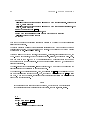
Here is another example:
!COPY PS:<SYSTEM>FILE.CMD PS:<OPERATOR>FILE.CMD
Ret
Using input recognition, the command looks like this:
!COPY
Esc
(FROM) PS:<SYSTEM>FILE.CMD
Esc
(TO) PS:<OPERATOR>FILE.CMD
Ret
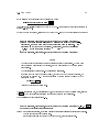
A further facility, related to input recognition, is invoked by the question mark character, \?".
When you type a question mark in the middle of a command, TOPS{20 will tell you what kind of
parameter is required. For example:
!Build ? Old directory name being modified
or, New directory name being created
!Build
^ the input pointer is left at this spot
2
Command parameters are also called arguments .
ix
This example shows that when you type \?", TOPS{20 tells you what kind of parameter the program
wants to see. It then retypes your command, up to the point where you typed the question mark,
and it awaits your further input.
If you type accurately, the command lines shown in this manual will be accepted and interpreted
correctly by TOPS{20. If you choose, you can use input recognition. In most cases, if you press
the Escape key after you type a command or a parameter, TOPS{20 will provide guide words or
instruct you to press the Return key.
Input recognition oers several advantages. First, you can double{check your typing, because the
completed command as printed by TOPS{20 veries that your typing has been interpreted correctly.
Second, you can minimize typing, because you need only type enough characters to make a unique
match with a command or parameter. And third, TOPS{20 prompts your next response, because
it prints guide words in parentheses.
How to Use this Manual
You might nd it helpful to be familiar with the information found in the TOPS{20 User's Guide ,
the TOPS{20 System Manager's Guide , and the TOPS{20 Operator's Guide . But you have to start
somewhere you can start with this manual, but be aware of the \Related Documents" listed above.
If you are installing a new system, read the entire manual. If you are generating a tailored Galaxy,
read Appendix E.
Typographical conventions used in this manual are described in Table 0.1.
The commands you type are underlined in this manual. If you type accurately, all you have to do
is perform the indicated function and verify that your actual terminal output resembles the sample
output. Be sure to include the spaces shown in the command lines.
Remember that systems dier in memory size and peripherals, so steps that describe conguring
memory, conguring network printers and disk drives, and assigning logical unit numbers to tape
drives, require you to type the values that are correct for your system, and not the sample parameters
shown in the examples.
If your terminal output does not resemble the sample output, rst read all of the instructions after
the word \Error" then choose the recovery procedure that corrects your problem.
Note
The version and edit numbers in this manual may dier from those printed on your
terminal. The numbers printed on your terminal must be equal to, or greater than, the
numbers in this manual.
Time estimates are included so that you know about how long a step takes. Times are estimated to
the nearest minute, so don't worry if a step takes somewhat longer or shorter than this.
x
Table 0.1: Typographical Conventions
Symbol
Ret
Esc
@
@@
!
!!
$
<CTRL/\>
<CTRL/x>
^X
Typewriter Font
Typewriter Font
^X
Italic Font
Spaces
Small Caps
fXjYjZg
.
.
.
Indicates
The \Return" or \Enter" key.
The \Escape", \ESC", \ALT", \ALTMODE", or \PREFIX" key.
The TOPS{20 Exec program's prompt character as represented
in this manual. Your actual prompt may dier, as the prompt can
be set by each user. As delivered, your system will prompt with
\Host@".
The Exec's subcommand prompt.
The Exec's Enabled prompt character as represented in this manual. Your actual prompt may be dierent.
The Exec's Enabled subcommand prompt.
In some programs, e.g., DDT, the echo of Esc
Press and hold the CTRL (Control) key, then type the backslash
key. When typed on the console terminal, this key summons the
micro{command processor, which prompts by typing either XKL-1>
or XKL-1% the former signies that a program is running, the latter
signies that the PDP{10 instruction{set processor is halted.
Press and hold the CTRL (Control) key, then type the other indicated key, in this example \x".
The echo of <CTRL/x>. For example, pressing <CTRL/z> echoes as
^Z. Note that pressing <CTRL/x> does not always echo with ^x on
your terminal. For example, <CTRL/\> has no echo at all.
Actual (or typical) output from the computer. In running text,
this font also signies the actual name of a command or the name
of a le.
Actual input required in a command string. You must type such an
element in full or with an abbreviation acceptable to the system.
Generally, TOPS{20 commands and le names are not sensitive to
any dierence between uppercase and lowercase characters.
Actual input of <CTRL/X>
An input variable in a command string (for example, name or number). These are variables that you must determine.
Spaces are used to separate elements of a command. A space must
be input where shown. Generally, TOPS{20 will tolerate multiple
spaces where one space is shown.
The names of programs typically appear in small capital letters.
A list of alternatives within a command. You must specify one of
the alternatives in your command string. Do not type the braces
or the vertical bar in the actual command string.
This mark indicates that some of the lines in the example or gure
are not shown.
xi
Revision History
4 December 1995 to Present
This revision list has been created and added to the manual.
Class A warning has been added to the frontmatter and chapter 1.
Language describing the emergency power o connection was changed.
The installation procedure for the XTU{1 has been added.
The chapter on Galaxy has been added.
The frontmatter has been expanded.
Figures depicting the machine and the 16{bit to 8{bit converter were added.
xii
CONTENTS
xiii
Contents
Preface
Revision History
1 Site Preparation
1.1 Electrical
1.1.1 Power Connection
1.1.2 Emergency Power O Connection
1.2 Air Conditioning
1.3 Network Environment
1.3.1 Terminal Server
1.3.2 Network Printer
1.4 Radio Interference
v
xi
1
: : : : : : : : : : : : : : : : : : : : : : : : : : : : : : : : : : : : : : : : : :
: : : : : : : : : : : : : : : : : : : : : : : : : : : : : : : : :
: : : : : : : : : : : : : : : : : : : : : : : :
: : : : : : : : : : : : : : : : : : : : : : : : : : : : : : : : : : : : : :
: : : : : : : : : : : : : : : : : : : : : : : : : : : : : : : : : : :
: : : : : : : : : : : : : : : : : : : : : : : : : : : : : : : : : : :
: : : : : : : : : : : : : : : : : : : : : : : : : : : : : : : : : :
: : : : : : : : : : : : : : : : : : : : : : : : : : : : : : : : : : : : :
2 Physical Set Up
2.1 Unpacking
2.2 Assembly
2.2.1 Mounting
2.2.2 Battery Installation
2.3 Power Connections
2.3.1 Mains Power
2.3.2 Emergency Power O
2.4 External Device Connections
2.4.1 Console Terminal
2.4.2 Auxiliary Console
2.4.3 SCSI Devices
2.4.3.1 Connectors
2.4.3.2 General SCSI Cabling
2.4.3.3 DAT Drive Cabling
2.4.3.4 XTU{1 Cabling
2.4.3.5 The SCSI \Standard"
2.4.3.6 SCSI Target ID Selection
2.4.4 Network
2.5 Indicator Lamps and Jumpers
2.5.1 XKL -1 Processor
2.5.2 XRH -1 SCSI Bus Controller
1
1
1
2
3
3
3
4
5
: : : : : : : : : : : : : : : : : : : : : : : : : : : : : : : : : : : : : : : : : :
: : : : : : : : : : : : : : : : : : : : : : : : : : : : : : : : : : : : : : : : : :
: : : : : : : : : : : : : : : : : : : : : : : : : : : : : : : : : : : : : :
: : : : : : : : : : : : : : : : : : : : : : : : : : : : : : : :
: : : : : : : : : : : : : : : : : : : : : : : : : : : : : : : : : : : : :
: : : : : : : : : : : : : : : : : : : : : : : : : : : : : : : : : : : :
: : : : : : : : : : : : : : : : : : : : : : : : : : : : : : :
: : : : : : : : : : : : : : : : : : : : : : : : : : : : : : :
: : : : : : : : : : : : : : : : : : : : : : : : : : : : : : : : : :
: : : : : : : : : : : : : : : : : : : : : : : : : : : : : : : : :
: : : : : : : : : : : : : : : : : : : : : : : : : : : : : : : : : : : :
: : : : : : : : : : : : : : : : : : : : : : : : : : : : : : : :
: : : : : : : : : : : : : : : : : : : : : : : : : :
: : : : : : : : : : : : : : : : : : : : : : : : : : :
: : : : : : : : : : : : : : : : : : : : : : : : : : : : :
: : : : : : : : : : : : : : : : : : : : : : : : : :
: : : : : : : : : : : : : : : : : : : : : : : :
: : : : : : : : : : : : : : : : : : : : : : : : : : : : : : : : : : : : : : :
: : : : : : : : : : : : : : : : : : : : : : : : : : : : : : :
: : : : : : : : : : : : : : : : : : : : : : : : : : : : : : : : : :
: : : : : : : : : : : : : : : : : : : : : : : : : : : :
5
6
6
6
8
8
9
9
9
9
10
10
11
11
11
13
13
14
14
15
15
CONTENTS
xiv
2.5.3 XNI -1 Ethernet Controller
2.5.4 XMG -1 Memory
: : : : : : : : : : : : : : : : : : : : : : : : : : : : :
: : : : : : : : : : : : : : : : : : : : : : : : : : : : : : : : : :
3 Starting the System
3.1 Initial Boot
3.2 Other Boot Operations
3.3 Abnormal Conditions
3.3.1 Board Swapping
3.3.2 Backplane Swapping
3.3.3 Disk Structure Problems
16
16
17
: : : : : : : : : : : : : : : : : : : : : : : : : : : : : : : : : : : : : : : : :
: : : : : : : : : : : : : : : : : : : : : : : : : : : : : : : : : : :
: : : : : : : : : : : : : : : : : : : : : : : : : : : : : : : : : : :
: : : : : : : : : : : : : : : : : : : : : : : : : : : : : : : : : :
: : : : : : : : : : : : : : : : : : : : : : : : : : : : : : : :
: : : : : : : : : : : : : : : : : : : : : : : : : : : : : :
4 System Administration
4.1 Conguring TOPS{20
4.1.1 System Denitions
4.1.2 Network Conguration
4.2 Users, Directories, and Accounts
4.2.1 Dening New Users
4.2.2 FINGER Data Base
4.2.3 Mail Aliases
4.2.4 Dening Directories
4.3 Console Terminal Operation
4.4 Security Considerations
4.4.1 Encrypted Passwords
4.4.2 Security Procedures
4.4.3 More Extreme Measures
4.5 Network Printers
4.5.1 Printing on a Printer Attached to a Terminal Server
4.5.2 Printing to a Remote Printer Queue or a Networked Printer
25
: : : : : : : : : : : : : : : : : : : : : : : : : : : : : : : : : : :
: : : : : : : : : : : : : : : : : : : : : : : : : : : : : : : : :
: : : : : : : : : : : : : : : : : : : : : : : : : : : : : : :
: : : : : : : : : : : : : : : : : : : : : : : : : : : : :
: : : : : : : : : : : : : : : : : : : : : : : : : : : : : : : :
: : : : : : : : : : : : : : : : : : : : : : : : : : : : : : : :
: : : : : : : : : : : : : : : : : : : : : : : : : : : : : : : : : : : : :
: : : : : : : : : : : : : : : : : : : : : : : : : : : : : : : :
: : : : : : : : : : : : : : : : : : : : : : : : : : : : : : : :
: : : : : : : : : : : : : : : : : : : : : : : : : : : : : : : : : :
: : : : : : : : : : : : : : : : : : : : : : : : : : : : : : :
: : : : : : : : : : : : : : : : : : : : : : : : : : : : : : : :
: : : : : : : : : : : : : : : : : : : : : : : : : : : : : :
: : : : : : : : : : : : : : : : : : : : : : : : : : : : : : : : : : : : : :
: : : : : : : : : : : : : :
: : : : : : : : : :
5 System Operation
5.1 Shutting Down the System
5.2 Booting the System
5.2.1 Rebooting the System for Stand{Alone Operation
5.3 File System
5.3.1 Creating Disk Structures
5.3.2 Creating Directories
5.3.3 File and Directory Protection
5.3.4 Managing Directory Access
5.3.5 File System Back Up
5.3.6 Periodic Tasks
5.3.7 Rebuilding the Boot Structure from Tape
5.3.7.1 Less Drastic Measures
5.3.7.2 Reinitializing the TOPS{20 File System from Tape
5.3.8 Formatting a Disk
5.4 Tape Backup
5.5 Tape Handling
5.6 The OPR Program
17
22
23
23
23
24
25
25
28
30
30
31
31
32
32
33
33
34
34
35
37
38
39
: : : : : : : : : : : : : : : : : : : : : : : : : : : : : : : :
: : : : : : : : : : : : : : : : : : : : : : : : : : : : : : : : : : : :
: : : : : : : : : : : : : : :
: : : : : : : : : : : : : : : : : : : : : : : : : : : : : : : : : : : : : : : : :
: : : : : : : : : : : : : : : : : : : : : : : : : : : : :
: : : : : : : : : : : : : : : : : : : : : : : : : : : : : : : :
: : : : : : : : : : : : : : : : : : : : : : : : : : :
: : : : : : : : : : : : : : : : : : : : : : : : : : : :
: : : : : : : : : : : : : : : : : : : : : : : : : : : : : : : :
: : : : : : : : : : : : : : : : : : : : : : : : : : : : : : : : : : :
: : : : : : : : : : : : : : : : : : : :
: : : : : : : : : : : : : : : : : : : : : : : : : :
: : : : : : : : :
: : : : : : : : : : : : : : : : : : : : : : : : : : : : : : : : :
: : : : : : : : : : : : : : : : : : : : : : : : : : : : : : : : : : : : : : : :
: : : : : : : : : : : : : : : : : : : : : : : : : : : : : : : : : : : : : : :
: : : : : : : : : : : : : : : : : : : : : : : : : : : : : : : : : : : : :
39
40
40
41
41
43
43
44
45
46
46
47
48
57
58
59
59
CONTENTS
xv
5.7 Other Periodic Tasks
5.7.1 Accounting Data
5.7.2 The BS:<SPOOL> directory
5.7.3 The SERR:ERROR.SYS le
: : : : : : : : : : : : : : : : : : : : : : : : : : : : : : : : : : : :
: : : : : : : : : : : : : : : : : : : : : : : : : : : : : : : : : :
: : : : : : : : : : : : : : : : : : : : : : : : : : : : :
: : : : : : : : : : : : : : : : : : : : : : : : : : : : :
6 Running the TOPS{20 UETP Package
6.1 Obtaining a Tape Drive
6.1.1 Systems without Tape Drive Allocation
6.1.2 Systems with Tape Drive Allocation
6.1.3 Using a Logical Name for the Tape Drive
6.2 Running the Standard Tests
6.3 Running Optional Tests
6.4 Deleting Temporary Directories
6.5 Release the Tape Drive
63
: : : : : : : : : : : : : : : : : : : : : : : : : : : : : : : : : :
: : : : : : : : : : : : : : : : : : : : :
: : : : : : : : : : : : : : : : : : : : : : :
: : : : : : : : : : : : : : : : : : : :
: : : : : : : : : : : : : : : : : : : : : : : : : : : : : : : :
: : : : : : : : : : : : : : : : : : : : : : : : : : : : : : : : : :
: : : : : : : : : : : : : : : : : : : : : : : : : : : : : :
: : : : : : : : : : : : : : : : : : : : : : : : : : : : : : : : : : :
Appendices
A 7{CONFIG.CMD Commands
A.1
A.2
A.3
A.4
A.5
A.6
A.7
A.8
60
60
60
61
Dening System{Wide Logical Names
Selecting an Editor
Dening Magnetic Tape Logical Unit Numbers
Dening the Local Time Zone
Specifying Daylight Savings Time
Directory Parameter Setting
Account Validation
Performance Improvements
A.8.1 Working Set Swapping
A.9 Scheduler Controls
A.9.1 Bias Control
A.9.2 Traditional Scheduling
A.9.3 Class Scheduling
A.9.3.1 Class Scheduling by a Policy Program
A.9.3.2 Class Scheduling by Accounts
A.10 File Archiving and Migration Parameters
A.10.1 Archive Tape Recycle Period
A.10.2 Migration Tape Recycle Period
A.11 Tape Drive Allocation
A.12 Accounting Shift Changes
A.13 Controlling System Message Levels
A.14 Network Information
A.15 Designating O{line Structures
A.16 The Login Structure Facility
A.17 Preventing Fast Login
A.18 Password Management
A.18.1 Designating Minimum Password Length
A.18.2 Changing Passwords Regularly
A.18.3 Disallowing Certain Passwords
63
64
64
66
66
69
71
71
75
75
: : : : : : : : : : : : : : : : : : : : : : : : : :
: : : : : : : : : : : : : : : : : : : : : : : : : : : : : : : : : : : : :
: : : : : : : : : : : : : : : : : : : : :
: : : : : : : : : : : : : : : : : : : : : : : : : : : : : : :
: : : : : : : : : : : : : : : : : : : : : : : : : : : : :
: : : : : : : : : : : : : : : : : : : : : : : : : : : : : : : :
: : : : : : : : : : : : : : : : : : : : : : : : : : : : : : : : : : : : :
: : : : : : : : : : : : : : : : : : : : : : : : : : : : : : : :
: : : : : : : : : : : : : : : : : : : : : : : : : : : : : : :
: : : : : : : : : : : : : : : : : : : : : : : : : : : : : : : : : : : : :
: : : : : : : : : : : : : : : : : : : : : : : : : : : : : : : : : : : :
: : : : : : : : : : : : : : : : : : : : : : : : : : : : : : :
: : : : : : : : : : : : : : : : : : : : : : : : : : : : : : : : : :
: : : : : : : : : : : : : : : : :
: : : : : : : : : : : : : : : : : : : : :
: : : : : : : : : : : : : : : : : : : : : : : :
: : : : : : : : : : : : : : : : : : : : : : : : : : :
: : : : : : : : : : : : : : : : : : : : : : : : : :
: : : : : : : : : : : : : : : : : : : : : : : : : : : : : : : : : : :
: : : : : : : : : : : : : : : : : : : : : : : : : : : : : : : : :
: : : : : : : : : : : : : : : : : : : : : : : : : : : :
: : : : : : : : : : : : : : : : : : : : : : : : : : : : : : : : : : : :
: : : : : : : : : : : : : : : : : : : : : : : : : : : : : :
: : : : : : : : : : : : : : : : : : : : : : : : : : : : : : :
: : : : : : : : : : : : : : : : : : : : : : : : : : : : : : : : : : :
: : : : : : : : : : : : : : : : : : : : : : : : : : : : : : : : : : :
: : : : : : : : : : : : : : : : : : : : :
: : : : : : : : : : : : : : : : : : : : : : : : : :
: : : : : : : : : : : : : : : : : : : : : : : : : :
76
76
77
79
79
80
81
81
81
82
82
82
83
83
83
84
85
85
85
86
86
87
87
88
89
89
89
89
90
CONTENTS
xvi
A.19 Dumping on Non{fatal System Errors
A.20 Disabling the Console Terminal for Operator Output
A.21 Enabling the Access Control Program
A.22 Setting Console Terminal Parameters
A.23 Commands not Supported in the TOAD -1 System
A.23.1 Assigning MSCP{served Disk Drives
A.23.2 Cluster Data Gathering
A.23.2.1 Cluster Information
A.23.2.2 Cluster Sendalls
A.23.3 The Magtape Command
A.23.4 The Printer Command
A.24 Running SETSPD Interactively
: : : : : : : : : : : : : : : : : : : : : : : : : :
: : : : : : : : : : : : : : : : : :
: : : : : : : : : : : : : : : : : : : : : : : : : :
: : : : : : : : : : : : : : : : : : : : : : : : : : :
: : : : : : : : : : : : : : : : : : :
: : : : : : : : : : : : : : : : : : : : : : :
: : : : : : : : : : : : : : : : : : : : : : : : : : : : : :
: : : : : : : : : : : : : : : : : : : : : : : : : : :
: : : : : : : : : : : : : : : : : : : : : : : : : : : : :
: : : : : : : : : : : : : : : : : : : : : : : : : : : : : :
: : : : : : : : : : : : : : : : : : : : : : : : : : : : : : :
: : : : : : : : : : : : : : : : : : : : : : : : : : : : : :
B OPR Commands
C CheckD Commands
D TOPS{20 Start Up Operations
D.1 TOPS{20 Initialization
D.2 TOPS{20 System Variables
97
103
109
: : : : : : : : : : : : : : : : : : : : : : : : : : : : : : : : : : :
: : : : : : : : : : : : : : : : : : : : : : : : : : : : : : : :
E Generating a Tailored Batch and Spooling System
E.1 Restoring the GALAXY Source Files
E.1.1 Restoring the Galaxy Sources
E.1.2 Verify
E.2 Running the GALGEN Program
E.3 Assembling the New GALAXY System
E.4 Shutting Down the Old GALAXY System
E.5 Starting up the New GALAXY System
E.6 Making Your New GALAXY System Permanent
: : : : : : : : : : : : : : : : : : : : : : : : : : :
: : : : : : : : : : : : : : : : : : : : : : : : : : :
: : : : : : : : : : : : : : : : : : : : : : : : : : : : : : : : : : : : : : : :
: : : : : : : : : : : : : : : : : : : : : : : : : : : : :
: : : : : : : : : : : : : : : : : : : : : : : : : :
: : : : : : : : : : : : : : : : : : : : : : : :
: : : : : : : : : : : : : : : : : : : : : : : : : :
: : : : : : : : : : : : : : : : : : : :
F TDBOOT Command Summary
F.1 Macro{console commands
F.2 Micro{console commands
Index
90
91
91
91
92
92
93
93
93
94
94
94
: : : : : : : : : : : : : : : : : : : : : : : : : : : : : : : : :
: : : : : : : : : : : : : : : : : : : : : : : : : : : : : : : : :
109
111
113
114
114
119
120
126
128
131
134
137
137
173
181
1
Chapter 1
Site Preparation
This chapter describes the requirements at the location where the TOAD -1 System is to be installed.
1.1 Electrical
The two electrical requirements are that power be supplied to the system and, if the system is to
be installed in a computer room, that a means be provided to disconnect electrical power (including
battery power) from the system.
1.1.1 Power Connection
The TOAD -1 System can be powered from either 110 VAC 20A or 220 VAC 10A, 50{60 Hz. A
separate circuit is recommended for this system, especially if it is powered from 110 VAC. The
power inlet on the rear panel of the machine is an IEC{950 connector mating power cords to plug
into a variety of standard electrical outlets are available. We have attempted to supply a cable that
will plug into the receptacle type common in the country to which the machine is shipped other
types may be acquired, either from XKL, or from local suppliers.
1.1.2 Emergency Power O Connection
The TOAD -1 System contains a battery which provides power during interruptions of the regular
AC source.
According to Article 645 of the 1996 (U.S.) National Electrical Code (NEC), some locations are
classied as \Information Technology Equipment Rooms" i.e., computer rooms. Such locations
require a \Disconnecting Means" (informally, an emergency power o button, or \EPO") which
shall disconnect power to all equipment in the room. The disconnecting means shall also disconnect
CHAPTER 1. SITE PREPARATION
2
the supply and output circuits of Uninterruptible Power Supply (UPS) systems installed within the
computer room the disconnecting means shall disconnect the battery from its load1.
When the TOAD -1 System is installed in a computer room, it must be attached to the Disconnecting
Means. The back panel contains a connector for this purpose. That connector should be wired in
parallel with any other devices that are connected to the EPO circuit (110/220VAC). The system
is furnished with an EPO control cable and with a \T" connector. This connector accepts the EPO
cable and it presents the EPO signal on two female connectors. Plug one of the female connectors
into the connector on the backpanel the second connector allows you to extend the EPO circuit to
another system in daisy-chain fashion, so that all will shut down together when the Disconnecting
Means is activated.2 To avoid current overload in the control cables, no more than 10 systems should
be attached to a single daisy{chain.
The site should be equipped with control connection to the EPO circuit, brought to an electrical
box (on the wall, or as code permits, in the sub{oor). The connector is:
RKF{30 Female plug/female thread bulkhead connector
Turck, Inc.
3000 Campus Drive
Minneapolis, MN 55441
The EPO control cable has three wires. The connector position nearest the notch is chassis ground.
Facing the female connector from the connector side (not the wire side) and moving in a clockwise
direction from the ground pin, the other two connector pins are EPO source (110/220 VAC) and
return (neutral). Actuation of the Disconnecting Means should provide power on the EPO source
wire for a sucient duration so that the connected devices respond. (The circuits supplied by the
Disconnecting Means should be powered from a source other than those that it intends to disconnect.)
The TOAD -1 System includes a 4 m EPO control cable, XKL part number 50024{00003, that can
connect a system to the wall box, or it can connect one system to another. Cables can be extended
by connecting one to another.
1.2 Air Conditioning
The TOAD -1 System dissipates up to 1500W, depending on the number of modules and I/O devices
mounted in its cabinet. Adequate air circulation and cooling must be provided to maintain the inlet
air temperature in the range 10 C|40 C (50 F|104 F). Airow through the cabinet is rated at
350 ft3 /min (10 m3/min).
If the inlet air temperature rises too high, or if the airow is restricted, the system will protect itself
by shutting down abruptly. An attempt has been made to give the operating system a warning in
this case in some multi{fault scenarios, the system could crash, leading to loss of data. Therefore,
adequate environmental control is highly recommended.
Consult local building code requirements.
Some backpanels contain two EPO connectors in this case, the male connector accepts the incoming EPO cable,
and the female connector is available to extend the EPO circuit to another system.
1
2
1.3. NETWORK ENVIRONMENT
3
1.3 Network Environment
1.3.1 Terminal Server
The TOAD -1 System is designed to be part of a networked computing environment. Consequently,
(nearly) all terminal connections to the system are virtual terminals, or TCP connections. These may
originate in several ways: from another computer that supports TCP/IP, from a network terminal,
or from a terminal server which provides TCP/IP support for RS{232 devices that do not have that
capability.
A network terminal server also will support a wide variety of devices that use an RS{232 connection,
either as a command input, or as a status{reporting port. User programs running on the TOAD -1
System can form connections to devices through their terminal server, and can then use these
connections to monitor or control the attached devices.
1.3.2 Network Printer
A printer is a special case of an RS{232 device that can be controlled through a TCP connection. If
a printer is attached to a terminal server, then any number of computers (not necessarily being all
the same type) can gain sequential access to it. The print spooling programs need only to open a
TCP connection to the printer's port on the terminal server, pass the data, and close the connection
when done. The terminal server then resolves competing requests for service, and eective sharing
of the printer is automatic.
Alternately, a printer that supports TCP/IP internally can be attached directly to an Ethernet
segment, so that it is available to several systems. In this case, the printer's TCP/IP service resolves
competing connection requests, providing sequential access to that printer.
A third option is to equip a printer with an external box that provides the TCP/IP service. Such a
device attaches to the Ethernet on one side it accepts TCP connections there. The printer attaches
to the other port it operates solely on command from the adapter box. In this case, the adapter
box resolves contending requests, and the printer is eectively shared.
Finally, print service may be handled by other networked computers (e.g., UNIX systems) the
physical connection between a printer and such a machine can be anything supported by that
machine's operating system.
CHAPTER 1. SITE PREPARATION
4
1.4 Radio Interference
Notice:
The TOAD -1 System has been tested and found to comply with the limits for
a Class A digital device, pursuant to part 15 of the (U.S.) FCC Rules. These
limits are designed to provide reasonable protection against harmful interference
when the equipment is operated in a commercial environment. This equipment
generates, uses, and can radiate radio frequency energy and, if not installed and
used in accordance with the instructional manual, may cause harmful interference
to radio communications. Operation of this equipment in a residential area is likely
to cause harmful interference in which case the user will be required to correct the
interference at his own expense.
5
Chapter 2
Physical Set Up
This chapter describes how to unpack your TOAD -1 System and connect it to the world.
You should receive the following items, depending on what you have ordered:
The system main chassis, in a crate axed to a pallet.
The battery, in a shipping carton.
Software, Manuals, and sundries. This carton contains the software (one DAT tape), one blank
DAT tape, manuals (including this one), the system power cord (appropriate to your country),
and the EPO cable.
If the XTU{1 nine{track tape was ordered, there will be two cartons. The large carton is the
tape drive and its power cord. The second carton contains the 15 ft (5 m) 8{bit dierential
SCSI cable, an 18 in (.5 m) 16{bit SCSI dierential cable, the 16{bit to 8{bit SCSI converter
box, and an 8{bit dierential SCSI terminator.
The following tools are required for installation:
#2 Phillips{head screwdriver
1/2 inch socket & ratchet driver
7/16 inch nut driver
7/64 inch hex driver
2.1 Unpacking
The system is shipped in a crate axed to a pallet. We recommend that the entire crate be placed
near the installation site before unpacking. (If your system includes a 9{track tape drive, it will
arrive in a separate box.)
CHAPTER 2. PHYSICAL SET UP
6
To unpack the system, remove all 5/16 inch bolts (ratchet driver and 1/2 inch socket) that hold
the top and sides of the exterior packing box together. This will expose the interior packing crate,
resting on the shipping pallet. Slide the crate o the pallet. Disassemble the interior packing crate
by cutting the plastic strapping. This will leave you with a nice, shiny TOAD -1 System. Move the
system cabinet to its nal position. You may retain the packing crate in storage, in case the system
must be repacked and shipped to another location.
2.2 Assembly
2.2.1 Mounting
If the system is free{standing, no additional assembly is required. (The sides of the cabinet should
be blue.) Place the system in the desired location, and go on to the next step.
If the system is to be mounted in a rack, this should be done rst, along with any peripheral
equipment that is to be installed in the same rack. (In this case, the sides of the box should be
aluminum{colored, and rack{mount ears should be visible.)
This system is quite heavy when fully assembled. If it is to be mounted in a rack, XKL recommends
that the system cabinet be supported on angle{bracket rails rated for a 150 pound (70 Kg) load.
The rack{mount ears are not intended to bear the full load of the cabinet they should be used to
secure the system to the front rails of the rack.
Due to the weight of the system, some arrangements of equipment in a rack are susceptible to tipping
over. Equipment mounted in a rack should be arranged so as to provide a low center of gravity.
Special precautions should be taken to secure equipment located in seismically active regions.
2.2.2 Battery Installation
The battery is shipped in a separate package.
Safety Warning
Turn o the AC power at the system's main breaker.
Disconnect the AC power cord.
Remove rings, bracelets, watches, and any other metallic objects from your
ngers, hands, and wrists. Also remove loose necklaces, neck chains, dangling
earrings, and any other jewelry that might come into contact with parts of
the machine. There is quite enough energy stored in the battery to cause a
serious burn if it should discharge through any such object.
2.2. ASSEMBLY
7
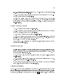
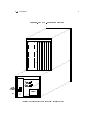
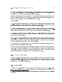
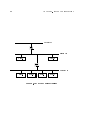
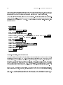
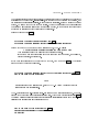
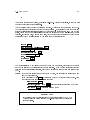
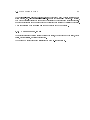
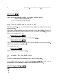
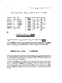
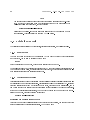
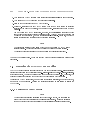
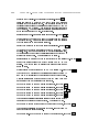
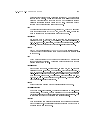
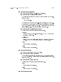
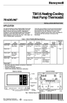
Figure 2.1: TOAD -1 System Rear View
c c ccccccc
c c
c c
c c ccccccc
1 2 3 4 5 6 7
Main
Breaker
AC Input
EPO
i
Battery
Breaker
Battery
Connector
Battery
(Battery Compartment is Open Upper Rear Cover is Removed)
8
CHAPTER 2. PHYSICAL SET UP
Facing the back of the machine (where the power cord attaches), the battery compartment is behind
the perforated cover panel that occupies the right two{thirds of the lower section of the machine (to
the right of the panel with the main AC breaker and power inlet). Remove the screws that secure
the back cover panel remove the cover panel. Refer to Figure 2.1 which depicts the system with the
battery compartment open.
The internal battery breaker is located on the left wall of the compartment, on the partition that
separates the battery compartment from the AC power inlet and power supply compartment. Turn
o the internal battery breaker by pulling its handle towards you the numeral \0" and the word
\OFF" should be visible on the far side of the breaker handle when the breaker is o.
The battery is heavy handle it carefully. Orient the battery so that when the battery is installed,
the battery cables will be close to the rear of the system (i.e., cables toward you). There are four
threaded posts protruding upwards from the bottom of the battery compartment. Remove the ange
nut from each of these posts. Put the battery in the compartment, aligned so that the slots on the
base of the battery are over the threaded posts. Use the ange nuts to secure the battery to the
bottom of the battery compartment.
Connect the battery cable to the connector located on the left wall of the battery compartment, just
below the battery breaker. Match the colors of the battery cable to the colors on the connector.
Turn the battery breaker on: push the handle away from you the numeral \1" and the word \ON"
should be visible on the breaker handle when the breaker is on.
The main system cooling fan is located at the top front (away from you) of the battery compartment.
Verify that your installation does not interfere with the movement of the fan assembly. (The fan
blades should turn easily by hand. Due to the construction of the fan motor, the fan will demonstrate
a preference to stop at particular positions.)
Reinstall the back cover panel, securing all the screws. Reconnect the AC power cord.
2.3 Power Connections
2.3.1 Mains Power
The power connection is an IEC{950 male connector, mounted in the lower left in the back of the
system (facing the rear of the cabinet). Connect the power cord to this plug.
Plug the system into either a 110|120 VAC 20A circuit or to a 208|240 VAC 10A circuit. The
power system automatically detects the line voltage and adjusts itself. As noted in Section 1.1,
XKL recommends that this system be connected to a separate circuit, especially if the system is to
operate on 110|120 VAC.
The main circuit breaker is both the system power on/o switch and a protective device. This
breaker switches both AC and DC power. Overload on either AC or DC will trip this breaker. It is
located on the rear of the unit near the AC power connection, protected from accidental actuation
by a sheet{metal tab.
A second circuit breaker, accessible inside the battery compartment, interrupts only DC power from
2.4. EXTERNAL DEVICE CONNECTIONS
9
(and recharging power to) the battery. If this breaker is left o, the battery will not be available to
keep the system running when line power fails, nor will the battery recharge. This breaker is tripped
by an EPO event (see below) it must be reset manually after an EPO event.
2.3.2 Emergency Power O
Provided the system is properly connected into a computer room Emergency Power O (EPO)
circuit, as described in Section 1.1.2, actuation of the room EPO switch will cause the battery
circuit breaker to trip. (Presumably, the operation of the EPO switch will also remove AC power
from the system at the same time.) This breaker must be reset manually, after removing the cover
from the battery compartment, as described in Section 2.2.2. The breaker trip coil is set for 65
VAC and it disconnects when the breaker trips. Thus, the EPO circuit will operate correctly at any
voltage from 90 VAC to 240 VAC without overloading the breaker coil.
2.4 External Device Connections
Connections to SCSI buses, Ethernets, and the console terminal are protected by a sheet metal
cover over the upper half of the rear of the cabinet. To gain access to these connections, remove the
three screws securing the cover to the cabinet then slide the cover straight back, lifting it slightly.
Replace the cover after making the connections and securing cabling to external devices.
2.4.1 Console Terminal
The console terminal port is a DB25 plug (male) wired as a DTE (Data Terminal Equipment)
connection, mounted on the back panel of the XKL -1 module the pin assignments are shown in
Table 2.1. To connect to a local terminal (also a DTE), one needs a null modem or correctly wired
cable.1 This cable may be strain{relieved by securing the cable to one of the wire{tie anchors
installed in the lower rear panel.
The port characteristics are xed at 9600 baud, 8 data bits (no parity), 1 stop bit.
2.4.2 Auxiliary Console
The auxiliary terminal port is presented as a DB25 plug, wired as a DTE (Data Terminal Equipment)
connection. The (standard) signal assignments are shown in Table 2.1. To connect this port to a
modem (a DCE, Data Communications Equipment), one needs a modem cable.2 As noted above
for the console port, attachment of the auxiliary port to another DTE requires a null modem or a
special cable. Port serial characteristics are the same as for the console port.
The correct cable connects pin 2 of the console port to pin 3 of the terminal, and pin 3 of the console port to pin
2 of the terminal.
2 Modems vary, so some experimentation may be required. Start with a cable that is wired \straight through", i.e.,
pin 1 to pin 1, pin 2 to pin 2, etc.
1
CHAPTER 2. PHYSICAL SET UP
10
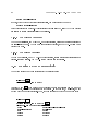
Pin
1
2
3
4
7
8
20
22
Function
Console Aux
Frame Ground
TxD (from XKL -1)
RxD (to XKL -1)
RTS (from XKL -1)
Signal Ground
CD (to XKL -1)
DTR (from XKL -1)
RI (to XKL -1)
?
?
?
?
?
?
?
?
?
?
?
?
Table 2.1: RS{232 Connector Pin Assignment
The auxiliary terminal port functions only when it is enabled by a console command see Section 4.3.
2.4.3 SCSI Devices
The TOAD -1 System will be delivered with SCSI cables and \target identication" numbers already
set up in a working conguration. The following material is for your reference in the event that
you plan to change the conguration of SCSI buses and devices. If your conguration includes the
XTU{1 reel{to{reel tape drive, you may want to familiarize yourself with the description of XTU{1
cabling in Section 2.4.3.4
All system disk and tape devices must conform to the SCSI{2 (Small Computer Systems Interface)
standard. Since this \standard" allows for a number of interface choices which do not interoperate,
XKL has selected an actual standard from those allowed: a 16{bit dierential bus from the controller
ports. A bus runs from the controller port to a number of 16{bit dierential devices, after which it
may be narrowed to 8{bit dierential. Once the bus width has been reduced, only 8{bit devices can
be attached farther from the controller.
Each XRH -1 controller presents four fast, wide, dierential SCSI{2 buses. In principle, any device
meeting the SCSI{2 specication could be connected however, operating system support is limited
to those devices that we have fully tested. At present, the operating system supports disk drives from
several vendors, one vendor's reel{to{reel tape drive, one vendor's DAT drive, and one vendor's DLT
cartridge tape drive. There are some peculiarities unique to 36{bit computers and others unique to
the XRH -1: customers should consult with XKL technical sta before attempting to connect devices
that are not recognized by the system and its software.
2.4.3.1 Connectors
All connectors on the XRH -1 are high{density, 68{pin, SCSI{2/3 connectors, often referred to as
P{connectors. This connector supplies all the signal and control lines to implement the dierential
16{bit SCSI{2 bus.
Some external devices, notably reel{to{reel tape drives, are available with an 8{bit electrical interface only. The most common connector for these devices is a low{density, 50{pin, \micro ribbon"
2.4. EXTERNAL DEVICE CONNECTIONS
11
connector. (Beware: this connector is also used in many SCSI{1 applications, but most SCSI{1
cables are single{ended and these will not work properly with dierential SCSI devices.) To make
the transition between dierent connectors and dierent bus widths, XKL has available an adapter
box (XKL part number 30008{00001), which may be secured to the rear panel of the system cabinet. A system ordered with a reel{to{reel tape drive will come equipped with this adapter box and
necessary cables.
2.4.3.2 General SCSI Cabling
Each SCSI bus starts at the XRH -1 (electrical termination is provided there). Cables that serve
internal devices loop into the I/O section of the unit, visit devices there, and reappear on the back
panel of the I/O section at that point, a terminator must be installed, or the bus must be extended
to external devices (where it will terminate). A cable serving only external devices attaches directly
to the XRH -1 and runs to the rst device. All buses must be electrically terminated at their ends.
If the last device does not have internal termination, the bus must be terminated with a dierential
terminator. A 16{bit bus must be terminated with a 16{bit dierential terminator (XKL part
number 50026{00001). If the bus travels through the 16{bit to 8{bit SCSI converter box, the 8{bit
end of the bus must be terminated by the last device or by an 8{bit dierential terminator(XKL
part number 50000-00001).
Strain relief anchors for external bus cables are mounted on the lower rear panel. We recommend
securing all external cables to these anchors with cable ties.
2.4.3.3 DAT Drive Cabling
The (internal) DAT drive is available with a single{ended SCSI interface only, so a bus converter is
located inside the I/O section of the cabinet to change the dierential bus to a single{ended one.
This single{ended SCSI bus comes out of the converter and goes to the DAT drive it is terminated
on both ends. There are four 50{pin connectors on this internal bus cable, intended for additional
internal DAT drives that may be mounted in the chassis. It is not intended that this single{ended
bus be used for any devices external to the system frame.
2.4.3.4 XTU{1 Cabling
The XTU{1 reel{to{reel (9{track) tape drive is available with a narrow (8{bit) dierential SCSI
electrical interface only. The XTU{1 includes the cables, the 16{bit to 8{bit converter box, and the
bus terminator necessary to connect the XTU to the system.
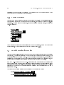
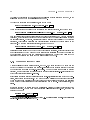
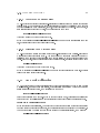
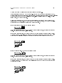
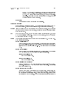
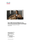
Install the 16{bit to 8{bit dierential SCSI converter box (p/n 30008{00001). The converter box
mounts on the exterior rear of the machine, across the upper portion of the power inlet panel, just
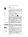
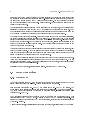
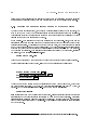
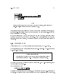
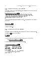
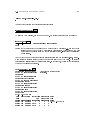
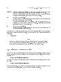
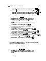
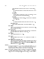
above the \XKL" logo, as depicted in Figure 2.2.
Remove the uppermost screw from the right edge of the power inlet panel loosen the screw opposite
that one at the left edge of machine frame. Orient the converter box so the 68{pin connector points
up and the 50{pin connector points towards you. (Note: the 50{pin connector is actually larger
CHAPTER 2. PHYSICAL SET UP
12
Figure 2.2: XTU 16{bit to 8{bit SCSI Converter Box
lx l
l
l
68{pin Connector
50{pin Connector
c l
XKL
logo
Main
Breaker
AC Power
Inlet
Converter Box
Position and Orientation
l
2.4. EXTERNAL DEVICE CONNECTIONS
13
than the 68{pin connector.) Slide the \ear" of the converter box under the loosened screw, replace
the screw that was removed, and tighten both screws.
Attach the tape drive to the SCSI bus as follows: use the short 16{bit dierential SCSI cable from
an XRH -1 port3 to the converter box. Use the long 8{bit dierential SCSI cable from the converter
box to the tape. (Use the strain relief anchors, mounted on the lower rear panel, to secure the
external bus cable with cable ties.)
The tape will have two connectors for SCSI cables: plug the long cable into one connector and the
8{bit dierential SCSI terminator into the other it doesn't matter which is which at the tape.
2.4.3.5 The SCSI \Standard"
CAUTION: Not everything that is called \SCSI" is electrically compatible with the particular bus
types that XKL supports. Most SCSI devices are single{ended. In the TOAD -1 System, most
internal and all external SCSI devices are dierential, for increased data transfer reliability. Single{
ended terminators and many plausible{looking cables are not compatible with the TOAD -1 System.
XKL can supply a variety of cables and terminators that are of the correct type. Based on the
descriptions above, competent local vendors may be able to supply cables and terminators that are
compatible.
2.4.3.6 SCSI Target ID Selection
In general, XKL recommends that devices be congured to spread activity as evenly as practicable
over the available buses.
On each SCSI bus, the target ID for each device (including the XRH -1) must be unique. After
selecting which devices are to be attached to which SCSI bus, the person conguring the system must
assign target IDs for each device and congure those devices accordingly. The only consideration
that recommends one ID over another is that 8{bit devices are limited to having IDs in the range 0
through 7, and 8{bit devices can \talk" only to an initiator whose ID is in the range 0 through 7.
For this reason, we recommend that the XRH -1 ID be set to zero further, on a bus that contains
both 8{bit and 16{bit devices, the 16{bit devices ought to be assigned IDs in the range 8 through
15.
The default target ID for the XRH -1 is 0 on each SCSI bus. This can be changed by the following
console command (see Section 3.2):
XKL-1%Define Scsi-Id
slot bus number target ID Ret
The target ID for each disk and tape unit must be set according to its manufacturer's specication.
Since there are as many schemes as device types, the best plan is to follow the manufacturer's
directions.
Systems delivered from XKL will have device target IDs set so that all are usable. Individual
3 If no XRH -1 port is available, remove a 16{bit SCSI terminator from a SCSI bus and install the short 16{bit
cable instead of the terminator.
CHAPTER 2. PHYSICAL SET UP
14
peripherals ordered from XKL, to be added to an existing system, will come with appropriate
directions.
2.4.4 Network
Four independent connections to the IEEE 802.3 standard Ethernet are supported on each XNI -1.
Each connection can be made via twisted pair (10{Base{T) or via an AUI device.
The AUI connection is used when a port is connected to a Media Access Unit (MAU) either directly
or with an AUI cable. Examples of such MAUs are multiport repeaters and transceivers for coaxial
cables.
For a 10{Base{2 (thin coaxial cable) connection, the MAU is customarily attached to the 15{pin
AUI connector at the back of the XNI -1 board. Coaxial cable is run between the MAU and two
other connection points.4
An RJ{45 female connector on the backpanel of the XNI -1 supplies a 10{Base{T connection.
Twisted{pair cable must be provided, running between this connector and the 10{Base{T hub
providing network access. This hub is the MAU in this case it is usually located at some distance
from the system.
Network address assignment and other conguration steps are discussed in Section 4.1.2.
2.5 Indicator Lamps and Jumpers
The system has three lamps on the front panel to indicate the operating status of the machine:
Green indicates that DC power is on.
Red
The combination red/green indicates that the system is running on its battery, because
of a loss of AC power.
The red lamp lit by itself indicates that the internal temperature has been exceeded (or
that the cooling air path was obstructed), and that the machine has shut itself down.
Yellow indicates the level of activity on the system. It has been carefully calibrated at the factory
so that the lamp is o when the system is idle, and it is at full brightness when there is
so much excitement that no job is getting much service.
In addition to the lamps on the front of the machine, there are indicator lamps visible through the
module cover panel of each of the dierent system boards. The approximate behavior of each of
these lamps is described in the following subsections.
4
Or terminate one end of the coax at the MAU and run coax to one other connecting point.
2.5. INDICATOR LAMPS AND JUMPERS
15
2.5.1 XKL -1 Processor
Above each RS{232 port connector is a green lamp that is turned on when that port is activated.
The indicator for the console port will normally be on. The indicator for the auxiliary console port
will be on only when that port is activated see Section 4.3.
In the lower part of the XKL -1 module board cover, a single red lamp, labeled \Fault", indicates the
occurrence of a microcode or private memory (MemA) parity error. Either of these errors is fatal
the XKL -1 will either restart or halt5 , depending on whether a jumper block is installed at J3 on
the board. Below this lamp are four green lamps that are used to signal the progress of self{tests,
performed at power{on. These lamps are o during normal system operation.
A jumper block is normally installed at J3, to cause restart in case of error. This jumper is located
on the component side of the PC board, between the red LED and a 50{pin header, very close to
the module cover panel. If this jumper block is removed, the XKL -1 will halt on the occurence of
either a microcode or MemA parity error.
2.5.2 XRH -1 SCSI Bus Controller
The XRH -1 has ve indicator lamps. The red \Fault" lamp is located between the Port 0 and Port 1
SCSI connectors. There are four green lamps, one located above each SCSI bus connector. Each
lamp reects the status of the corresponding SCSI bus.
After initialization, during normal operation, the \Fault" light should be o each green lamp is
turned on when the corresponding bus is on{line and idle. While a transaction is in progress on a
bus, the corresponding lamp is turned o. Thus, a blinking green lamp indicates SCSI bus activity.
Even when TOPS{20 is idle, these lights should blink as the operating system scans the devices to
see if their status has changed. After initialization, if the \Fault" lamp is o, a green lamp that
remains o indicates either a bus that has been taken out of service or one that is \hung". (SCSI
devices on a malfunctioning bus can be moved to working buses until the hardware can be xed or
replaced. If it is necessary to recongure the SCSI buses, it is best to do so with the system shut
down and power o.)
During the XRH -1's power{up (and hard reset) sequencing, blinking green lamps indicate that self{
testing is in progress the fault light may be on for 30 seconds or so during this initialization and
self{testing.
The fault lamp is lighted continually if the self{test fails, or if the XRH -1 has released \need power"
during a power failure. If the fault lamp blinks, the board is malfunctioning. If the fault light stays
on, a fatal XRH -1 error has been detected, or a power failure is pending.
5 In this context, \halt" means that execution of the microcode will stop (in contrast to the PDP{10 HALT
instruction that stops the macro{code program). When the microcode is stopped, there are no console functions
whatsoever.
16
CHAPTER 2. PHYSICAL SET UP
2.5.3 XNI -1 Ethernet Controller
The red \Fault" lamp indicates a microcode parity error on the XNI -1. If it blinks continuously or
stays on, the module is faulty.
Each port is decorated with 5 lamps to indicate the status of that port. These lamps all turn on
briey when power is applied and when the operating system resets the controller.
On each port, the \Link Pol" lamp should be on. If a cable is connected to the RJ{45 connector
and to a 10{Base{T hub, then when trac appears on the cable, this lamp may go out, indicating
that the polarity of the connection is reversed. If this happens, recheck the 10{Base{T wiring. The
XNI -1 automatically corrects for this polarity reversal, so data reception will still work normally.
The operating system lights the \Port OK" lamp for each port to which it expects a network to be
connected. The lamp will not light from the time power is turned on until the rst time TOPS{20
starts operation.
The \Link OK" lamp should be on when a live 10{Base{T cable is plugged into the RJ{45 connector,
but o for a thin{wire/MAU connection, or if a cable is disconnected at its far end.
The \Tx" lamp lights when data is being sent from the XNI -1.
The \Rx" lamp lights when data is arriving at the XNI -1. An active network will cause the \Rx"
lamp to icker, regardless of whether or not the TOAD -1 System is the target of the trac.
2.5.4 XMG -1 Memory
There is a single green lamp on this module. It is turned on when initialization software has cleared
memory and has determined that the module functions correctly. This lamp indicates that the
module is available to the operating system (\on line").
17
Chapter 3
Starting the System
This chapter describes what you should see on the console terminal when rst starting a TOAD -1
System. Console commands , i.e., commands that can be typed on the console and auxiliary console
only, to boot the operating system are described.
Before turning the power on, be sure that the installation steps described in Chapter 2 have been
completed. Connect a console terminal to the TOAD -1 System's console port, and turn on the
console terminal. Make sure the terminal parameters are set as described in Section 2.4.
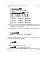
3.1 Initial Boot
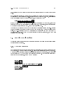
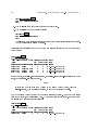
Assuming a console terminal is connected to the TOAD -1 System when you rst apply power, you
should see something resembling the following:
System Processor (XKL-1, 1995) Ver - 1133
TDBoot version 1.2(25)-1
System ID 32., system options 0
Microcode version 2, options 200000
All system startup parameters are enabled.
Testing cache
Testing pager
Polling and verifying bus configuration
Memory configuration and test:
The following line may take
Slot 3. XMG-1 (32MW), Testing: SDdAa, On line at LPN 0
Starting not-ready devices
Device configuration:
Slot
Device
1.
1./ 1.
: Seq. Access
"HP
", "C1533A
Serial number: N/A
5 minutes
", "9503"
CHAPTER 3. STARTING THE SYSTEM
18
Tape MTA0:
3./ 8.
: Direct Access "SEAGATE ", "ST15150W
", "0017"
Serial number: 00658476
Structure PS:(BS), 0. of 1. unit
Begin AUTO-BOOT delay, type ^C to abort or any other key to proceed now]
Note:
The memory testing takes about 5 minutes (for each 32 M word module). As long as the
program displays the \spinner", which is a succession of characters that appear to spin,
progress is being made. There will be a short delay after the letter \S" is printed following
\Testing:". There will be a one{ to two{minute delay following each of the letters \D",
\d", \A", and \a".
Error: If you see no typeout at all, suspect the console terminal, its parameters, and its communications wiring.
If the typeout indicates a problem with the conguration, type <CTRL/C> to stop the boot
process and attempt the command
XKL-1%Define Configuration *
followed by
XKL-1%.i
Ret
Ret
Note the period preceding the \i"
If these fail to correct the problem, seek help from XKL.
This typeout displays various system resources as the CPU discovers them: where (and how much)
memory is present, and the layout of each SCSI bus that has responding disk or tape drives on it.
(Devices switched o or unplugged from power will not be shown, since they do not respond.)
About one minute after the message \Begin AUTO{BOOT delay", the system will go on to boot
itself. The delay allows the operator an opportunity to interrupt the automatic process and direct
the system to a dierent activity.
If the process is interrupted (by typing <CTRL/C>), the system will respond with the prompt XKL-1%,
which shows that the micro command parser is ready for a command the % signies that the PDP{10
instruction set processor is halted.
The console command Boot loads and starts the operating system or a stand{alone program. In the
absence of a structure or lename as a parameter to Boot, the default boot string will select the le
name in the absence of a default boot string, the le named <SYSTEM>MONITR.EXE will be sought
on the TOPS{20 auto{boot structure . Another structure and/or lename may be specied as a
parameter to the Boot command the replacement name string is eective for that command only.
The default boot string can be specied as the parameter to the console command Define Boot as
shown here:
XKL-1%Define Boot
le speci
cation Ret
Thereafter, the le speci
cation string will be used in subsequent Boot commands.
The auto{boot structure is preassigned when systems are shipped from the factory it may be
changed using the CheckD program. Details are in Appendix C.
3.1. INITIAL BOOT
19
If there is no auto{boot structure, you must specify a structure name in the Boot command.1 If
there is no bootable structure at all, you can boot from tape, by supplying an explicit boot target
(e.g., mta0:) The le to be booted must be the next one on the tape (usually the rst).
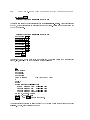
If the auto{boot process is allowed to continue, the typeout will look similar to that depicted below.
The underlined portions represent responses that you must type on the terminal.
Note
The customer initially receives an uncongured system which will type various error
messages during initialization. These error messages are indicated below. (Your mileage
may vary.) Hopefully, the error messages will indicate the name of the le that must be
changed to correct the problem. Please follow the conguration and customization tasks
described in Chapter 4 to correct these problems.
Reboot requested]
Using default string: ""]
Structure PS:]
Directory <ROOT-DIRECTORY>]
Directory <SYSTEM>]
File PS:<SYSTEM>MONITR.EXE.1]
Loading .................]
File entry vector is at 1,,161, length is 5]
PDVA at 1,,141077]
Filled through LPN 2126]
Starting at 1,,161]
PS mounted]
%Error in interface number in SYSTEM:INTERNET.ADDRESS file
nea^#<n>, nnn.nnn.nnn.nnn, ethernet
Loading Internet host names]
%Bad host number format in SYSTEM:HOSTS.TXT
net : x^xx.xxx.0.0 : YourNetworkName ::::
OK]
% LOADGW: Unknown keyword in file:<SYSTEM>INTERNET.GATEWAYS.1
ALWAYS XXX.XXX.XXX.XXX
^
SETSPD: Processing SYSTEM:7-CONFIG.CMD
TOAD-1 System, TOPS-20 Monitor 7(102113)-1
Monitor built Thu 29-February-1996 8:20AM
Network Time Setter
? JSYS ERROR: No number for that host name
(This will be corrected when the internet parameters are set up.)
Enter current date and time:
1
up.
If there is no auto{boot structure, TOPS{20 will also need to be told the name of the structure to use as it starts
CHAPTER 3. STARTING THE SYSTEM
20
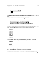
Enter the date and time in the form \mm-dd-yy hhmm" or as shown in the example. Type Ret to
tell TOPS{20 to go on. TOPS{20 will repeat the date back to you and ask for conrmation. If you
have entered the correct date, type \Y" and Ret otherwise, type \N" and Ret and TOPS{20
will ask for the date and time again.
Enter current date and time: 1 March 96 16:25
You have entered Friday, 1-March-1996 4:25PM,
is this correct (Y,N) y
Why reload?
Ret
Ret
The response to \Why reload" is entered into the system error le, BS:<SYSTEM-ERROR>ERROR.SYS
as part of the reload record. The rst word of the response must be one of a small number of
keywords for a list of valid responses, you may type \?" and Ret . For the time being, we shall
type \New install system".
Notes
If you do not respond to the \Why reload" question within 60 seconds, the system
assumes \Other" and continues the startup procedure.
If you type an unrecognized response to \Why reload", TOPS{20 will complain and
prompt you again.
Why reload? new install system
Run CHECKD?
Ret
Next, TOPS{20 asks if you want to run the CheckD program. If you respond \Yes" to this question,
CheckD will be started and it will check the disk to see if it can nd any \lost pages". The functions
of CheckD are further explained in Section 5.3.6 and in Appendix C. Although it is sometimes
worthwhile (and sometimes mandatory) to run CheckD, for this time we shall respond \No" and
type Ret .
Note
If you do not respond to this question within 60 seconds, TOPS{20 will answer the
question \No" and continue the startup procedure.
Run CHECKD? no
Ret
3.1. INITIAL BOOT
1-Mar-96 16:25:09 DDMP: Started
1-Mar-96 16:25:10 SETSPD: Checking for crash DUMP
SYSJOB 7(78) started at 1-Mar-96 1625
1-Mar-96 16:25:28 SYSJOB: Job 3: @ LOGIN OPERATOR
1-Mar-96 16:25:28 SYSJOB: Job 1: @ LOGIN OPERATOR
1-Mar-96 16:25:29 SYSJOB: Job 4: @ LOGIN OPERATOR
1-Mar-96 16:25:29 SYSJOB: Job 5: @ LOGIN OPERATOR
1-Mar-96 16:25:30 SYSJOB: Job 6: @ LOGIN OPERATOR
1-Mar-96 16:25:30 SYSJOB: Job 2: @ LOGIN OPERATOR
1-Mar-96 16:25:32 SYSJOB: Job 5: Host@ ENABLE
1-Mar-96 16:25:32 SYSJOB: Job 5: Host! RUN SYSTEM:RAISE-QUOTA
1-Mar-96 16:25:32 SYSJOB: Job 6: Host@ ENABLE
1-Mar-96 16:25:32 SYSJOB: Job 6: Host! RUN SYSTEM:MAILST.EXE
1-Mar-96 16:25:33 SYSJOB: Job 2: Host@ ENABLE
1-Mar-96 16:25:33 SYSJOB: Job 5: Host! RUN SYSTEM:LPTSPL/BACK
1-Mar-96 16:25:33 SYSJOB: Job 2: Host! RUN SYSTEM:SMTJFN /BACK
1-Mar-96 16:25:33 SYSJOB: Job 4: Host@ ENABLE
1-Mar-96 16:25:34 SYSJOB: Job 1: Host@ ENABLE
1-Mar-96 16:25:34 SYSJOB: Job 1: Host! RUN SYSTEM:SETNAM
1-Mar-96 16:25:34 SYSJOB: Job 4: Host! RUN SYS:MMAILR
1-Mar-96 16:25:34 SYSJOB: Job 1: Host! GET SYS:OPR
1-Mar-96 16:25:34 SYSJOB: Job 3: Host@ ENABLE
1-Mar-96 16:25:34 SYSJOB: Job 3: Host! CD DOMAIN:
1-Mar-96 16:25:36 SYSJOB: Job 3: Host! RUN RESOLV
1-Mar-96 16:25:36 SYSJOB: Job 5: Host! RUN SYSTEM:LPTSPL/BACK
1-Mar-96 16:25:37 SYSJOB: Job 2: Host! RUN SYSTEM:NETSRV
1-Mar-96 16:25:37 SYSJOB: Job 5: LPTSPL0]
1-Mar-96 16:25:37 SYSJOB: Job 1: Host! DEPOSIT SHUTUP -1
1-Mar-96 16:25:38 SYSJOB: Job 5: Host! RUN SYSTEM:TCPSPL/BACK
1-Mar-96 16:25:38 SYSJOB: Job 5: Host! RUN SYSTEM:TCPSPL/BACK
1-Mar-96 16:25:38 SYSJOB: Job 5: TCPSPL0]
1-Mar-96 16:25:38 SYSJOB: Job 5: Host! RUN SYSTEM:TCPSPL/BACK
1-Mar-96 16:25:40 SYSJOB: Job 5: TCPSPL1]
1-Mar-96 16:25:40 SYSJOB: Job 5: Host! RUN SYSTEM:TCPSPL/BACK
1-Mar-96 16:25:40 SYSJOB: Job 5: TCPSPL2]
1-Mar-96 16:25:40 SYSJOB: Job 1: Shared page made private]
1-Mar-96 16:25:40 SYSJOB: Job 1: Host! START
1-Mar-96 16:25:41 SYSJOB: Job 1: OPR> SILENCE
1-Mar-96 16:25:41 SYSJOB: Job 1: OPR> TAKE SYSTEM:SYSTEM.CMD
1-Mar-96 16:25:42 SYSJOB: Job 1: OPR> TAKE SYSTEM:PRINTER.CMD
1-Mar-96 16:25:42 SYSJOB: Job 1: OPR> PUSH
1-Mar-96 16:25:43 SYSJOB: Job 1: End of COMAND.CMD.1
1-Mar-96 16:25:43 SYSJOB: Job 1: @
ENABLE
1-Mar-96 16:25:43 SYSJOB: Job 1: !
^ESET LOGIN ANY
1-Mar-96 16:25:43 SYSJOB: Job 1: !
POP
1-Mar-96 16:25:44 SYSJOB: Job 1: OPR> WAIT 60
1-Mar-96 16:26:43 SYSJOB: Job 1: OPR> WAIT 60
1-Mar-96 16:27:42 SYSJOB: Job 1: OPR> RESTORE
21
CHAPTER 3. STARTING THE SYSTEM
22
Once the system comes up to this point, you can log in as Operator. Type <CTRL/C> to start the
Exec the Exec will print a brief banner line and prompt with the \@" character. Type the Login
command:
@login operator xkl-toad
Ret
As you type this command, the initial password, xkl{toad , will not echo to the output your terminal
should look like the following:
Your TOAD from XKL, TOPS-20 Monitor 7(102113)-1
@login operator
End of COMAND.CMD.1
Host@
Security Note
We recommend that you change the password for Operator immediately . A
full discussion of the security implications is in Section 4.4, page 33 that
section also shows how to change a password. Please remember your
new password.
A variety of site{specic alterations must be made to integrate the system with your network
environment and to tailor it to the user community. These are described in Chapter 4.
3.2 Other Boot Operations
Up to now in this section, we have assumed that only one terminal (physically connected to the
console RS{232 port) was active this led to some ambiguities in referring to the commands typed,
since all were typed at the same terminal.
Throughout this document, we attempt to distinguish console commands from others. A console
command will be recognized only when it is typed in response to the prompt XKL-1> or XKL-1% on
the console (or the auxiliary console).
The console commands are documented in the TOAD -1 System Architecture Reference Manual ,
in the appendix on TDBoot. These commands are used to boot the system, to dene various
operational parameters, mostly related to the hardware installed, and to perform diagnostics to
isolate a fault in a malfunctioning system. Some console commands can be issued while TOPS{20 is
running. To get the attention of the console command interpreter while the system is running, type
<CTRL/\> on the console this should produce the prompt XKL-1>. Then issue a console command.
To give the console terminal back to TOPS{20, type the console command:
XKL-1>Continue
Ret
3.3. ABNORMAL CONDITIONS
23
For some console commands, the TOPS{20 system must be stopped. Such commands, if attempted
at the XKL-1> prompt, will result in an error message in that case, the running program (TOPS{20)
can be stopped by the command:
XKL-1>Halt
XKL-1
Ret
Once the program is stopped, all console commands are possible.
Caution
Console commands that are illegal while the system is running are likely to destroy
the \state" of the computer and make it impossible to continue the operation that was
interrupted. Where possible, make sure that timesharing operations have been shut down
in an orderly way before giving any such command. If timesharing operations are active,
the system can be shut down by the procedure documented in Section 5.1, page 39.
3.3 Abnormal Conditions
This section can not be an exhaustive treatment of everything that could go wrong. This section
discusses some of the anomalies in system startup that might be caused by maintenance activties.
3.3.1 Board Swapping
In some maintenance and diagnostic activities, the system circuit boards may be moved to dierent
backplane slots. The system is designed to operate properly regardless of the permutation of its
circuit boards. However, the bootstrap program, TDBoot, will notice that the boards have been
moved, and it will not automatically boot the system.
If you get a message from TDBoot announcing that it has detected a change in the conguration
of the boards, you must give the console command
XKL-1%define configuration *
Ret
to refresh TDBoot's understanding of which board is where. Thereafter, the system should boot
without unusual manual intervention.
3.3.2 Backplane Swapping
The system is electronically identicatied by a ROM installed on the system backplane. If the
backplane is changed without moving the ID ROM from the old backplane to the new one, the
system will not boot properly because it can't nd the auto{boot disk.
24
CHAPTER 3. STARTING THE SYSTEM
In this case, the best thing to do is to change the ID ROM on the backplane.
Otherwise, boot the system by manually specifying the structure from which to boot. As TOPS{20
starts, it will be unable to nd the right structure automatically, so it will ask for a structure name.
When TOPS{20 is running, use the CheckD program to redene the auto{boot system ID for your
boot structure see Appendix C.
3.3.3 Disk Structure Problems
See Section 5.3, page 41.
25
Chapter 4
System Administration
This chapter covers some of the most important aspects of customizing TOPS{20 to serve your user
community. Topics covered include the conguration of TOPS{20 for your network environment,
the creation of login accounts for users, and the creation of le{storage directories. This chapter
also discusses security considerations in the network environment, and the conguration of printers
on the network.
4.1 Conguring TOPS{20
4.1.1 System Denitions
The logical name BS: represents the name of the boot structure . The boot structure serves two
dierent purposes:
The boot structure is automatically recognized by TDBoot as the structure from which to
load the TOPS{20 monitor.
TOPS{20 recognizes the boot structure, also known as the system structure as the rst struc-
ture to mount, as the structure to swap on (for which reason this structure is also known as
the swapping structure), and as the structure from which to load programs and command les
for system initialization (e.g., Setspd and SYSTEM:7-CONFIG.CMD).
The boot structure is identied with two marks: it must be agged as an \auto{boot" structure, and
it must contain a system ID that matches the current system's identication number. Moreover, to
be recognized by TDBoot, it must be the only structure marked this way. In order to be recognized
by TOPS{20 as the system structure, the boot structure must also contain swapping space.
The le directory BS:<SYSTEM> contains many les by which the system is congured and customized.
A number of les need to be altered at each site to customize the operation of TOPS{20. These
alterations may be done any time after the initial boot is completed. Most of the changes take eect
CHAPTER 4. SYSTEM ADMINISTRATION
26
the next time the system is rebooted.
These les are generally protected from being changed by unprivileged users. Thus, to eect the
changes described below, you must be use a privileged user name, e.g., Operator, and have the
privileges active, via the Exec command:
@enable
!
Note that after you use the Enable command, the Exec changes its prompt character from \@" to
\!". The dierent prompt helps to remind you that whatever privileges you have are now active.
The following are the les that deserve particular attention in customizing:1
BS:<SYSTEM>7-CONFIG.CMD
This le contains several kinds of commands that are carried out when the system starts
running. Each command is system{wide in its application. The sections of this le are
{ System{wide logical name denitions: these are almost identical to job{wide logical names
but are dened for everyone. You will need to make specic changes to dene your site's
printing environment.
{ Batch system and Scheduler settings: whether or not to establish classes of jobs and the
fraction of the machine's time to allot to each. If no classes are dened, whether or not
to let batch jobs compete with interactive ones. Whether or not to bias the system to
favor one or the other of either compute{bound or interactive jobs.
{ Disk/tape subsystem declarations: how tape archiving works, whether or not to have
TOPS{20 process the labels of labeled tapes, what to do with unlabeled tapes, and which
disk structures are shared, if any.
{ Enabling the use of a \Login Structure": the logical name PS: represents the name of
the public structure , the structure that contains le directories for individual users of
the system. This structure is also known as the login structure since it contains the
users' main directories and their passwords. Often, PS: and BS: are the same structure.
However, a customer may dene a login structure other than BS: by using CheckD to
mark a structure as the login structure, and then enabling the use of the login structure
by a command in this le.
{ Timezone and daylight time parameters.
{ Miscellaneous settings: password length, what accounting is being done, and a few others.
Appendix A contains a detailed listing of these commands and their parameters. That appendix describes how to declare the system name, and change the system defaults for system
devices, accounting, performance improvements, scheduler controls, le archiving and migration, as well as other system functions.
1 Many of these les are provided as templates with modication dates 100 years prior to their correct modication
date. This is done so that these les will not replace more recent versions when loading from tape. Copies of these
les are also placed in BS:<SYSTEM.TEMPLATES> for reference.
4.1. CONFIGURING TOPS{20
27
BS:<SYSTEM>MONNAM.TXT
This le contains one line of text that begins the announcement text output to a terminal
when it rst connects to the system.
Whenever a user types <CTRL/C> before logging in, when a user makes an initial connection
to TOPS{20, or when a user gives the Exec command:
@Information Version
Ret
the system prints a message similar to:
Your Toad from XKL, TOPS-20 Monitor 7(101604)-1
where \7(101604){1" is the version and edit number of the operating system. You can change
the system name, \Your Toad from XKL", by entering the name you want for your system
into the le BS:<SYSTEM>MONNAM.TXT.
The text of the system name can contain up to 105 characters. For practical purposes, it
should not exceed 32 characters to t on a single 72-character line of terminal output.
Be enabled be connected to BS:<SYSTEM> use the command:
!Copy TTY: MONNAM.TXT
Ret
Then enter the system name and type <CTRL/Z> to end the le.
Use the Copy command to give the system a new system name. After you enter the command,
the system waits for you to type the new name of your system. After you enter the new system
name, type <CTRL/Z>. In the example, the new system name is \Installation-test System".
!COPY TTY: MONNAM.TXT Ret
TTY: = MONNAM.TXT.1
Installation-test System^Z
!
(Note: the characters \^Z" are the echo of <CTRL/Z>.)
You can change this le at any time, but TOPS{20 reads the system name only when the
monitor is started (whenever you boot the system).
BS:<SYSTEM>TAPNAM.TXT
This le contains the abbreviated system name that will be written on the volume header label
of any labeled tape initialized by users of the system. (Presuming that you have congured
the system to process tape labels.) The system name in a volume header label has just ten
character positions, so you may have to abbreviate the system name to make it t in ten or
fewer characters.
BS:<SYSTEM>SYSTEM.CMD
This le contains a sequence of Opr commands that take care of a variety of housekeeping
chores when TOPS{20 begins operation. Opr is the system operator's utility program its
commands are described in Appendix B.
BS:<SYSTEM>PRINTER.CMD
One of the housekeeping chores that seems to need taking care of repeatedly is the denition
and startup of print spooling. Therefore, we recommend moving these commands into a
CHAPTER 4. SYSTEM ADMINISTRATION
28
separate le so that they can be invoked at need, without the overhead of a full startup via
the SYSTEM.CMD le.
BS:<SYSTEM>LOGIN.CMD
This le contains commands that are executed on behalf of each job at the time it is logged
in. These commands take eect before any commands in the user's LOGIN.CMD or COMAND.CMD
les, described in Section 4.2.
BS:<SYSTEM>COMAND.CMD
This le contains commands that are executed on behalf of each job at the time it is logged
in and whenever an Exec is created for an existing job. These commands take eect before
any commands in the user's COMAND.CMD les, described in Section 4.2.
BS:<SYSTEM>BEWARE-MESSAGE.TXT
This le contains a message that is presented to every user when an Exec is started on a
terminal for a new job. You may omit this le altogether, or place a message in it.
BS:<SUBSYS>LPFORM.INI
This le contains forms control denitions for the Lptspl print spooler. Lptspl is the spooler
that can send data to a printer that is attached to a serial port of a network terminal server.
More information is presented in Section 4.5.1.
BS:<SUBSYS>LPFORM.TXT
This le contains forms control denitions for the Tcpspl print spooler. Tcpspl is the spooler
that can send data to a network host or network printer that supports the lpd protocol see
Section 4.5.2.
4.1.2 Network Conguration
The les listed below aect the software that operates the network. In addition to the actual
information that directs the system in its use of the network, each of these les includes comments
that describe its function in greater detail than is presented below. Please read those comments as
you change the les.
BS:<SYSTEM>HOSTS.TXT
This le contains the names and IP network addresses of computer systems \known" to this
machine. The le is read at the time TOPS{20 starts operating, so that IP addresses of systems
mentioned in this le are known immediately. Among these might be names of systems on
your local net, names of gateways, and names of other service providers (e.g., name{lookup
services). Changes to this le can be made eective immediately by using the command:
!^Eset internet host-table
BS:<SYSTEM>INTERNET.ADDRESS
Ret
The rst character is
<CTRL/E>
This le contains commands that congure XNI -1 ports. Each XNI -1 port can be assigned
an IP network addresses and be told how it should expect to see data. There should be one
command line in the le for ,each active Ethernet port. Lines beginning with semicolons are
treated as comments. The following lines are examples:
4.1. CONFIGURING TOPS{20
29
nea#0, 198.55.36.131, ethernet, logical-network-mask:255.255.255.0, packet-size:1500, preferred
nea#1, 192.94.202.40, ethernet, logical-network-mask:255.255.255.240, packet-size:1500, preferred
nea#2, 192.94.202.230, ethernet, logical-network-mask:255.255.255.240, packet-size:1500, preferred
Changes may be made to this le while the system is running. They will automatically take
eect the next time the system is restarted, or they can be made eective immediately with
the command:
!^Eset internet address
BS:<SYSTEM>INTERNET.GATEWAYS
Ret
This le contains the address of at least one gateway to which the system may forward trac
when it knows nothing about how to route it. Generally, all trac destined for networks not
directly connected to the XNI -1must be forwarded through a network gateway. For example:
always 192.94.202.225
To notify TOPS{20 of changes to this le, use the command:
!^Eset internet gateway
DOMAIN:RESOLV.CONFIG
Ret
This le controls the way Internet host names are resolved into addresses. As shipped from
XKL, this le contains very few actual control lines, and a considerable number of comments,
indicating what local editing should be done. Edits to this le must reect the way the Domain
Name System (DNS) is set up for the network to which the TOAD -1 System is attached.
The minimum initial changes that should be made are to specify a remote search path, so
that DNS requests will be formed correctly, and to add any user names to the list of those
authorized to send resolver control messages. (Initially, the logical name DOMAIN: is dened
to be BS:<DOMAIN>.)
After editing DOMAIN:RESOLV.CONFIG, you can make the resolver take the changes by the
following commands:
Ret
Start the Resolver Control program
RSVCTL>boot Ret
Are you sure? yes Ret
RSVCTL>exit Ret
!domain:rsvctl
!
After all the necessary changes are made, it is good practice to shut the system down and then reboot
it to make sure that the changes actually produce the intended eects when the system restarts.
Section 5.1, page 39 describes how to stop the system in an orderly manner Section 5.2, page 40
describes how to reboot the system.
CHAPTER 4. SYSTEM ADMINISTRATION
30
4.2 Users, Directories, and Accounts
A user is a person. A person gains access to TOPS{20 through the Exec program's Login command.
In Login, the user identies himself or herself by supplying a user{name and a password. Once
logged{in, a user has a job which is connected to a directory . A directory is a repository for les.
A user{name is a name, assigned to the user by the system administrator, which identies the
login directory for the user. A user's login directory contains that person's mail le, other les
unique to that person, and information describing the person's access rights (group membership)
and privileges. Initially, following the successful completion of the Login command, the user's job
is connected to his or her login directory. To be connected to a directory means that the user has
\owner" access to the les in the directory by default, i.e., unless otherwise specied, les written
by the user will go into the connected directory. A job is a collection of processes that TOPS{20
runs on behalf of a user.
An account is a number or string, associated with a job or a le. Account strings (numbers) provide
ner resolution in cost{accounting when one person may be working on multiple tasks, each of which
may need separate time{ and resource{accounting. (TOPS{20 can be told to check the validity of
an account string.) The subject of \accounts" is mentioned here primarily to note that, as imprecise
human beings, we may on occasion lapse into terminological inexactitude and refer to a user{name
or login directory as an \account".
4.2.1 Dening New Users
Once the system is operational, you will probably want to dene users so that system access may be
shared. A user needs, at minimum, a directory with the login attribute (the default) and a password
dened. A directory, whether for a user or for le storage only, is created or modied by the Exec
command, Build:2
@enable
Ret
!build ps:<roget>
!!work 1000
!!perm 1000
Ret
Ret
Ret
!!password thesaurus
!!
Ret
Ret
!disable
@
Ret
Often, it is a good idea to provide generic LOGIN.CMD and COMAND.CMD les for each user as a starting
point. One common use for LOGIN.CMD les is to run a terminal query program that tries to decide
what kind of terminal the user is using for a session.
2 This use of the Build command is privileged you must be a privileged user (wheel or operator) and have your
privileges enabled.
4.2. USERS, DIRECTORIES, AND ACCOUNTS
31
The commands in LOGIN.CMD are processed only when a user logs in the commands in this le should
have job{wide application. Commands in COMAND.CMD are processed at login (after LOGIN.CMD) and
any time a new Exec command interpreter program is started.
In cases where a user should no longer be allowed to use a directory to log in, use the Build command
to add the frozen attribute to the directory. The directory retains all its properties, including the
ability to receive mail, but the user is no longer allowed to log in.
User Privileges
TOPS{20 recognizes that certain system maintenance and adminstrative functions are inappropriate
for general users these functions are restricted to users whose directories show that they have been
granted the \privilege" (or \capability") of overriding these restrictions.3
The three principal privileges in TOPS{20 are called \Wheel", \Operator", and \Maintenance".
The system administrator grants a privilege to a user by issuing an appropriate subcommand e.g.,
Wheel while using the Build command to create or change the selected user's directory.
\Wheel" and \Operator" are highly privileged states. They dier slightly in that \Operator" is a
bit more restrictive than \Wheel", but a user who has the \Operator" privilege can build a directory
that has the \Wheel" privilege.
The main use of \Operator" is for system backup and tasks to serve the operational requirements of
other users. An \Operator" can make any access to any le. (Read access to every le is required
for back up other access is required for le restoration, etc.) An \Operator" can communicate to
the output spoolers and batch system via the Opr program.
The main use of \Wheel" is for system adminstration tasks of an unusual nature, as might be
required of a trusted and skilled programmer.
The \Maintenance" privilege allows such activities as accessing the disk without going through the
le system. \Maintenance" is restricted to the tasks appropriate to testing and debugging system
components. A user who has only the \Maintenance" privilege can not (by any usual means) change
his or her own privileges or access les beyond what is usually permitted.
4.2.2 FINGER Data Base
Once a new user{name is created, it is a good idea to declare the identity of the user to the Finger
program's data base this is done with the Dbedit program, which maintains a data base matching
personal identities to user{names. This data base is used by the Finger program, which elds
queries about who is logged onto a system.
4.2.3 Mail Aliases
Depending on the e{mail system being used, one or more entries must be made in mail{forwarding
les to make the linkage between the name(s) under which mail is received and the directory (or
3 As a further safeguard, a user's privileges are not eective unless they have been turned on by the Exec's Enable
command.
CHAPTER 4. SYSTEM ADMINISTRATION
32
directories) to which it should be delivered. The details of how to do this are covered in the
documentation on the particular mailer being used.
4.2.4 Dening Directories
As noted in the previous section, a directory is a repository for les. In many installations, shared
data is stored in les that do not belong to any individual user. Such les may be stored in les{only
directories. To create this kind of directory, use the same Build process as before, but assign the
les{only attribute:
@enable
Ret
!build ps:<trashbin>
!!work 10000
!!perm 10000
!!files-only
!!
Ret
Ret
Ret
Ret
Ret
!disable
@
Ret
This will produce a directory that is accessible to any number of users, provided they have proper
access privileges. (Access privileges are covered in detail in Section 5.3.3.)
4.3 Console Terminal Operation
As noted in Section 2.4, provisions have been made for both a console terminal port and an auxiliary
terminal port. The intended distinction between these is that the console port is always active, while
the auxiliary port may be turned on or o. When the auxiliary port is turned on, it is eectively in
parallel with the console: any output to the console port is also delivered to the auxiliary port, and
any input from the auxiliary port is treated as though it had come from the console.
Both the XKL -1 microcode and the TOPS{20 operating system software rely on the console port
as the denitive place to print notice messages some error conditions make it impossible to record
error information anywhere else. For this reason, a printer or printing terminal with an RS{232
interface may be attached to the console terminal to preserve a log of events leading up to such a
serious system fault.
Activation of the auxiliary console port is controlled by two console commands:
f off j on g Ret
XKL-1%Define auxiliary-port f off j on g Ret
XKL-1%Set auxiliary-port
4.4. SECURITY CONSIDERATIONS
33
The auxiliary port may be turned on only through the console port it may be turned o from either
port.
Both the Define and Set commands apply immediately they dier in that the state established by
the Define command persists (and is re{established) after a power shutdown. Thus, in installations
where the auxiliary port is to be active at all times, the console command:
XKL-1%Define auxiliary-port on
Ret
should be given. This command alters the non{volatile conguration memory so that, after power
is turned o and back on, the auxiliary port will be turned on. Contrariwise, security considerations
may dictate dening the port to be o, except when it is set to be on.
This port may be connected to a modem to permit remote diagnosis of system problems. If this is
done, the auxiliary port should be turned on only when it is needed. While the auxiliary port is
active, the RS{232 signals RTS and DTR are asserted: RTS lets the modem know that data may
be transmitted at any time when DTR drops (because the port was deactivated), the modem will
disconnect the phone call.
4.4 Security Considerations
This section deals in general terms with techniques for reducing the ability of unauthorized persons
to gain access to your system.
4.4.1 Encrypted Passwords
Each disk structure species whether passwords for the directories are to be stored in plaintext or are
to be encrypted. To reduce the risk of a break{in, passwords on all structures should be encrypted.
While this does not guarantee password security, it eliminates an obvious threat. Disk structures
that are preloaded by XKL are dened with password encryption on. To specify that passwords be
encrypted on a disk structure, run the CheckD program:
@enable
!Checkd
Ret
Ret
TOAD-1 CheckD>define PS: password-encryption
TOAD-1 CheckD>exit
!disable
@
Ret
Ret
Ret
CHAPTER 4. SYSTEM ADMINISTRATION
34
4.4.2 Security Procedures
Other ways to reduce the threat of unauthorized access to the system and to data on it are:
Change the password for Operator.
This user{name, dened on all TOPS{20 systems, is a
well{known point of attack. The default password for this directory is likewise well{known
thus, anyone might attempt a Telnet connection to a TOAD -1 System, and log in. Since
the user{name Operator generally has wide access privileges to les on disks, the risk of data
theft or damage is high unless this password is changed before the system is attached to a
network, and kept secret thereafter.
To change the password for Operator, log in and perform the following commands:
@set directory password <operator>
Old password: xkl-toad
Ret
Your old password will not echo.
The new password will not echo.
new password Ret
password: new password Ret
New Password:
Retype new
@
Ret
Because the passwords that you type will not show on your terminal, this command requires
that you type the new password twice, to conrm that you typed it the same way both times.
Please remember your new password.
Control physical access to the machine, its console, and the auxiliary console. From the console
(and from the auxiliary console) it is easy to break into the system. (A person at the console
can start kernel DDT without rst logging in.) Therefore, when it is not in use, disable the
auxiliary console with the console command:
XKL-1%Define auxiliary-console Off
Ret
especially if this port is connected to an RS{232 line that is accessible from outside the machine
room.
Force users to change their passwords frequently. Avoid short, easily guessed passwords. See
Section A.18, page 89 for means by which these ideas can be implemented.
Consider installing network access controls and connecting the system to the network on the
protected side of the access barrier. This reduces the probability that an unauthorized person
will be able to break into the system from a remote computer anywhere in the world, even if
the passwords for a directory are known. This is discussed further in the following section.
4.4.3 More Extreme Measures
For those who worry professionally about information leakage, it should be noted that there are a
number of related ways that a determined attacker can learn things about a system in operation.
Once a successful Telnet connection has been made to a TOAD -1 System, several commands are
permitted in addition to Login among these are Finger, Systat, Help, and Information. Any of
4.5. NETWORK PRINTERS
35
these commands can leak information about logged{in user{names or system data to an unauthorized
person.4
If this level of leakage is unacceptable, the next defense is to permit only authorized incoming
Telnet connections, and deny all others. Volumes have been written on ways to set up networks
with more{or{less secure access the most convenient we know about is a security island architecture:
a subnet isolated by routers, to which a small number of (unsecured) machines are attached, as in
Figure 4.1.
These machines have two purposes: to authenticate users and to serve as a visible front for the
hidden parts of the network. Commonly, mail delivery services and Domain Name Service (DNS)
are handled through these machines. In addition, a number of self{monitoring processes may run
on these machines to aid in detecting and tracking break{in attempts.
The routers between the network segments are then charged with enforcing a connection policy.
Incoming TCP connection requests are allowed only in two circumstances: rst, from the public
side of the island to these authentication machines second, from the authentication machines to the
secure parts of the network. Established connections are allowed to pass through the routers, so
that TCP connections originating within the protected domain are not subject to authentication on
the security island.
A (lower{performance) variant of this architecture is called a rewall . The most common implementation of that scheme places a single machine between the public and private segments of the
network a third network port on the rewall machine serves the island net. Software in the rewall
machine then implements essentially the same policy outlined above. Such systems also oer some
added network addressing exibility, which may be interesting to some installations.
4.5 Network Printers
Since the TOAD -1 System was designed as a networked computer, all printing is via network printer
spooling. There are two basic ways that TOPS{20 does network print spooling. Both are managed
by the standard output queue management, but use dierent spoolers.
The rst method uses the Lptspl spooler, logical names of the form LAZPTn:, and the forms control
le SYS:LPFORM.INI to send printer data directly to a networked printer. In this case, all the printer
spooling is handled locally, and any special formatting instructions required by the printer (such as
PostScript) must already be present in the le that you queue to the local TOPS{20 printer queue.
The second method uses the Tcpspl spooler, logical names of the form PLPTn:, and the remote
queue{name control le SYS:LPFORM.TXT to forward a print job to a printer queue on another system5
which supports the lpd protocol that was originally dened for UNIX. In this case, the remote system
handles printer control it may preprocess the data in prescribed ways before printing. This scheme
should be considered carefully before implementation because it transfers some of the burden to
another machine.
You may rebuild your system's Exec to disallow those commands before log in.
This discussion also applies to those printers that can be attached directly to the network and which support the
lpd protocol.
4
5
CHAPTER 4. SYSTEM ADMINISTRATION
36
Public Net
LLLL
Auth-1
Island Net
Auth-2
LLLL
Host-a
Host-b
Host-c
Private Net
Host-d
Figure 4.1: Network Security Island
4.5. NETWORK PRINTERS
37
4.5.1 Printing on a Printer Attached to a Terminal Server
To print on a printer attached to a terminal server, you need to have a copy of the Lptspl spooler
running for each local printer queue that accesses it. This usually is achieved by running enough
copies of Lptspl under one job controlled by Sysjob.
Dene a system{wide logical name LAZPTn : with the value TCP:.rhost{rport , where n is the local
printer queue number (also known as the printer unit number), rhost is the remote host to connect
to, and rport is the remote port for access to the desired printer. (Actually, the logical name can be
anything you like, but it must be six or fewer characters to be acceptable to the queue management
system.) The denition of this system{wide logical name is usually achieved by adding a line similar
to the following in the le SYSTEM:7-CONFIG.CMD:
Define LAZPT0:
TCP:.KENT-4002
This would direct les queued to local printer unit 0 to be printed on the printer attached to port
4002 on host \kent".
To start printer spooling for each queue, you must issue Opr commands similar to the following:
OPR>SET PRINTER 0 FORMS POST
Ret
OPR>SET PRINTER 0 PAGE-LIMITS 0:5000
OPR>START PRINTER 0 /DEVICE:LAZPT0:
Ret
Ret
The rst command sets the forms{name associated with unit 0. This forms{name must also appear
in the le SYS:LPFORM.INI (see below).
The second command allows any length job up to 5000 pages to be printed by one request on unit 0.
Such a large number is required for a queue that handles PostScript, because the spooler tries to
count formfeeds in the text as a way of estimating the number of pages this count is unrelated to
the number of output pages for a page description language.
The third command starts the printer queue for Unit 0 and associates it with a network printer
LAZPT0:. It is necessary to use a system{wide logical name for this association, because the command
will not accept the le specication used to indicate the remote host and port.
There must be an entry in the le SYS:LPFORM.INI for each forms{name used for a network printer.
For example, the POST form (mentioned in the Opr command assigning the forms to a printer)
might have an entry like this:
POST/HEADER:0/BANNER:0/TRAILER:0/LINES:10000/WIDTH:132/EOJ:4/SYNC:4
The /HEADER:0/BANNER:0/TRAILER:0 switches prevent Lptspl from inserting text into a PostScript
stream. The /LINES:10000 prevents Lptspl from inserting extraneous formfeeds in the data stream.
The /WIDTH:132 prevents Lptspl from breaking lines excessively. The /EOJ:4 sends the value 4
(the ASCII character <CTRL/D>, which is interpreted as signalling the end of le by many PostScript
printers) at the end of a job. The /SYNC:4 sends the <CTRL/D> character between jobs. Sending
CHAPTER 4. SYSTEM ADMINISTRATION
38
both times ensures that the printer knows that a new job is starting, even if the preceding
one terminated abnormally or came from some other system that did not observe these niceties.
<CTRL/D>
4.5.2 Printing to a Remote Printer Queue or a Networked Printer
To print to a remote printer queue, or to print to a printer directly attached to the network,6 you
need to have a copy of the Tcpspl spooler running for each local printer queue that accesses it.
This is usually achieved by running enough copies of Tcpspl under one subjob controlled by Sysjob
(usually the same job that runs copies of Lptspl).
Dene a system{wide logical name of the form PLPTn : with the value TCP:.rhost , where n is the
local printer queue number (also known as the printer unit number) and rhost is the remote host
handling printer access. The logical name must be of the form given, as Tcpspl looks for the logical
name by appending the unit number to the string PLPT. The Tcpspl spooler automatically connects
to the remote host at port 515 (this is the port assigned for remote requests to lpd on UNIX systems).
The denition of this system{wide logical name is usually accomplished by adding a line, similar to
the following, to the le SYSTEM:7-CONFIG.CMD:
DEFINE PLPT1:
TCP:.fife
This command directs the Tcpspl for unit 1 to connect to host \fe" for remote print queueing.
To start printer spooling for each queue, issue Opr commands similar to the following:
OPR>SET PRINTER 1 FORMS POST
Ret
OPR>SET PRINTER 1 PAGE-LIMITS 0:5000
OPR>START PRINTER 1
Ret
Ret
These commands have exactly the same explanation as for the Lptspl case above, except that
the device PLPT1: is implied. The queue{name control le SYS:LPFORM.TXT, used by Tcpspl, is
dierent. Each of its entries associates a form{name with a remote print queue:
POST:LPT001/NAME:ps
identies the form type for print jobs in this queue. LPT001 identies this entry as being for
local printer unit 1 (the leading zeroes are required to make the name six characters). For largely
historical reasons, LPT001 implies that data will go to PLPT1:. The target queue name for the print
le on the remote host is identied by /NAME:ps. (These queue names are usually in /etc/printcap
on UNIX systems).
POST
6
This description presumes that a printer that is directly attached to the network accepts the \lpd" protocol.
39
Chapter 5
System Operation
This chapter describes some of the tasks that are required occasionally: shutting down timesharing,
rebooting, rebooting for stand{alone operation le system tasks: creating a le structure, creating
directories, backing up a le structure, checking le system consistency, rebuilding a le system from
a back up tape, and formatting a disk. Further, tape back up policies are described, as are a set of
periodic tasks.
5.1 Shutting Down the System
The TOPS{20 operating system generally has many activities under way at any moment. However,
some activities may require the entire system's resources. A period in which access to the system is
limited is called \stand{alone" time.
To terminate general system activities cleanly and to warn users of an impending shutdown, use the
Exec privileged command:
!^Ecease
fnow j date and time j +time from now g
Ret
As the designated time approaches, users are warned of the shutdown by messages on their screens.
When the shutdown time arrives, all jobs, except for job 0 and the job logged in on the console
terminal, are logged out. After the message \Ready for shutdown" appears on the console terminal,
the system is in \stand{alone" mode, where only Job 0 (system services) and the job on the console
terminal are active. To stop the system entirely (for example, before rebooting to resume normal
timesharing), use the character <CTRL/\> to summon the console prompt, \XKL-1>". Then give the
console command:
XKL-1>Shutdown
Ret
After a few moments the message \Halted" should appear, followed by the console prompt XKL-1%.
CHAPTER 5. SYSTEM OPERATION
40
5.2 Booting the System
The usual boot process is accomplished by typing the console command:
XKL-1%Boot
Ret
The Boot command loads an executable le into memory and starts the program. By default,
i.e., in the absence of parameters, the Boot command loads the le <SYSTEM>MONITR.EXE from the
auto{boot structure.
The default le name, i.e., the le name that Boot uses when none is specied in the command, can
be changed. The console command:
XKL-1%define boot
le name Ret
changes any part of the default le name (or switches, see below). This change is \permanent": it has
eect on every subsequent Boot command, until it is changed by another Define Boot command.
The Boot command also accepts a le{name as a parameter this parameter is eective just once,
in the command where it appears. This might be useful when experimenting with a new version of
the monitor, or when running a stand{alone diagnostic program.
Care for MONITR.EXE
The le BS:<SYSTEM>MONITR.EXE exists in the ordinary le system it is a valid .EXE
le. However, it has been specially contrived to run properly when loaded by TDBoot's
Boot command.
This le can be copied and it will remain bootable. It can be patched via FilDDT (File
DDT) and still be bootable. However, one patching technique (which worked in the
DEC versions of TOPS{20) will fail when performed on the TOAD -1 System: do not
copy MONITR.EXE by the sequence of Exec commands Get and Save. The Exec's Save
command will write a le that will not run properly when it is booted.
5.2.1 Rebooting the System for Stand{Alone Operation
Although TOPS{20 is a multi{user system, on some occasions, the system is wanted for stand{alone
operation, in which all or most of the system facilities are present, but from which general users are
excluded.
To boot TOPS{20 for stand{alone operation (presuming it is already shut down), you must start
the system in its debugger programer (called KDDT, for Kernel DDT). This is accomplished by
the /start:+3 option in the console Boot command. When KDDT is running, open the memory
location called DBUGSW, change the value stored therein to 2, and close the location. Then start
the system at location 161 (reported as the \entry vector location" by the Boot command). Your
console session should resemble the following:
5.3. FILE SYSTEM
41
XKL-1%boot /start:+3 Ret
Using default string: ""]
Structure PS:]
Directory <ROOT-DIRECTORY>]
Directory <SYSTEM>]
File PS:<SYSTEM>MONITR.EXE.1]
Loading .................]
File entry vector is at 1,,161, length is 5]
PDVA at 1,,141077]
Filled through LPN 2126]
Starting at 1,,164]
KDDT
DBUGSW/ 0 2 Ret Type \DBUGSW", slash, \2" and
161 Esc g
PS mounted]
.
.
.
The Esc will echo as \$".
press Return.
This procedure sets the debugging ag to 2 and starts TOPS{20. The debugging ag, called
\DBUGSW", has several purposes. For stand{alone operation, when \DBUGSW" has the value
2 or greater, the Sysjob program reads the le SYSTEM:7-SYSJOB.DEBUG instead of the usual
SYSTEM:7-SYSJOB.RUN le. If the .DEBUG le omits the line:
^Eset login any
then general login will not be allowed: jobs can be created only on the console and pseudo terminals.
The .DEBUG le may contain as much or as little of the normal system utilities as you nd appropriate
to your stand{alone environment.
5.3 File System
This section describes some of the tasks associated with the le system.
5.3.1 Creating Disk Structures
A disk structure is a named collection of similar disks that, together, contain a le system. A le
system is an organization of disks into a collection of named directories that contain named les.
A structure can be one disk or several. TOPS{20 supports structures up to a (present) limit of
about 17 Gigabytes. If there are multiple disks in a structure, they all must be compatible as to
capacity and geometry generally, this condition is satised if the disks are all the same make and
model.
CHAPTER 5. SYSTEM OPERATION
42
Arguing for multiple small structures is the notion that each is independent, each can be backed up
independently, and the failure of one does not mean the loss of data on the others. In favor of large
structures is the idea that one structure is easier to allocate and to manage than several.
A new disk structure is created using the CheckD program. If your disk(s) is(are) not yet formatted, see Section 5.3.8. This program knows how to label one (or more) formatted disk(s) so that
directories can be constructed by TOPS{20. A sample session to create a single{unit non{login
structure follows:
@Enable
!Checkd
Ret
Ret
TOAD-1 CheckD>create FROG:
Enter alias: FROG:
Ret
Ret
How many units in this structure? 1
Ret
DECIMAL Channel, Controller, and Unit numbers for logical unit 0: 4,-1,6
Number of pages to allocate for swapping? 0
Owner name? Operator
Ret
Ret
Ret
TOAD-1 CheckD>mount FROG:
Ret
Structure FROG: mounted]
TOAD-1 CheckD>define FROG: password-encryption
TOAD-1 CheckD>dismount FROG:
Ret
Ret
Structure FROG: dismounted]
TOAD-1 CheckD>exit Ret
!disable
@
Ret
Channel, Controller, and Unit numbers
The only question in this dialogue that requires advance preparation is the one about the channel,
controller, and unit numbers. The TOPS{20 channel number is related to the SCSI bus to which a
device is attached. Channels 0 to 3 are buses 0 to 3, respectively, on the rst XRH -1 channels 4 to 7
are buses 0 to 3, respectively, on the second XRH -1, etc. By the \rst" XRH -1 we mean the XRH -1
whose backplane slot has the lowest number the \second" XRH -1 is in a slot with a number higher
than the rst, but lower than any other XRH -1. The controller is ;1 for all supported SCSI devices.
The unit number is the SCSI Target ID of the device on which the structure is being created.
If you type \?" in response to this question, you will get a list of the devices available this list
includes all three numbers. (Better yet, use the Show command in CheckD before starting Create.)
This CheckD process creates a skeleton disk structure, with a few directories and housekeeping
les on it. A more complete description of the CheckD program commands is in Appendix C.
5.3. FILE SYSTEM
43
5.3.2 Creating Directories
As mentioned in Section 4.2.1, the Exec command Build is used to create or change a directory.
For directories that are to be used only for data storage (not used as login accounts), the attribute
les{only should be set during the Build operation.
5.3.3 File and Directory Protection
Every le and directory has a protection number that tells exactly who can do what to that le or
directory. The interpretation of this number is dierent for a directory than for a le. The number
consists of six digits divided into three pairs: the rst pair says what access to grant the owner, the
second pair says what access to grant to users of the directory's groups, and the third pair says what
access to grant anyone else.
To be recognized as the owner , you need to connect to or access a directory there is no registered
owner. The Exec commands Connect and Access are used to establish ownership access with
respect to les in a directory.1
To be considered a group member , your login directory must contain a user group number that
matches one of the directory group numbers recorded in the directory being accessed.
If a user has not established owner access or group access to a directory, that user is considered
other for the purpose of determining access to les.
File (and Directory) protection code numbers specify the types of access granted to \Owner",
\Group", and \Others". The protection code number has six octal digits. The left pair of digits specify the owner's access permissions the middle pair of digits specify group members' access
permissions the right pair of digits species other's access permissions.
The table below shows the kind of access each code allows the numbers are octal. To specify a
combination of allowed access privileges, OR the values for each eld into a two{digit protection
number for each class of access. Create a six{digit protection number from three groups of two{digit
numbers, one pair of digits for each of owner, group, and other access.
Value File access
00
02
04
10
20
40
77
No access to the le
Show lename in directory list
Append to the le
Execute the le
Write and delete the le
Read the le
Full access to the le
Directory access
No access to the directory
Reserved
Create les in the directory
Connect without a password
Reserved
File protections specify access
Full access to the directory
For example, le protection of 775200 means only the owner can change the le anyone in the
directory group can read it or execute it and access is denied to others.
1 In addition to establishing ownership access, the Connect command sets the default directory for le access to be
the connected directory.
CHAPTER 5. SYSTEM OPERATION
44
To display the protections of your les, use the Vdirectory (verbose directory) command, or the
command with the Protection subcommand.
Directory
To change the protection of a particular le, use the command:
@Set file protection
le name protection value Ret
To set the protection a le will get when it is created in a selected directory, use the command:
@Set directory file-protection-default
directory name protection value Ret
Each subdirectory is a le in a superior directory and has a le protection word. The only meaningful
value is 02, which controls whether or not the subdirectory is to be included in a listing of les in
the superior directory. Otherwise, operations involving a directory are controlled by the directory
protection . This directory protection number is interpreted according to the right column in the
table above. To change a directory's protection, use the command:
@Set directory protection
directory name protection value Ret
Particular mention should be made of the 10 code for directory protection. It should be included for
most directories in both the Owner and Group elds it is embarrassing to be asked for a password
when connecting to one of your own directories, and irritating to be asked for a password when
connecting to a directory in a group of which you are already a member.
5.3.4 Managing Directory Access
A further disussion of group access is needed. In TOPS{20, a group is dened by a group number
in both the directory to be accessed (the directory{group list) and in the login directory of the user
who is permitted the access (the user{of{groups list). When a job attempts an access to a target
directory, a match is required between an entry in the login directory's user{of{groups list and one
of the target directory's directory{group list.
It is possible to arrange directory access using these built{in facilities for systems with many directories, this approach is quite tedious. The Groupe program2 assists in managing group denitions
by remembering a name corresponding to each group number and allowing the system administrator
to add or remove user directories and le directories from named groups. This is still tedious, but
less so.
If a change in group membership is made to a user's login{directory, it will not normally take eect
until the next login. To make a new group available immediately to a logged{in job, the user must
enter the command:
@access <login
directory > Ret
2 Groupe (pronounced 'gr
up-e) is a contributed program, i.e., a program supplied by users. Such programs are
supplied \as{is" they are not supported by XKL.
5.3. FILE SYSTEM
45
Figure 5.1: .MIC File for System Back Up
@rewind mta0:
@set tape format high-density
@copy bs:<system>monitr.exe mta0:
page 40
Do not use
Save:
see Section 5.2,
@copy system:exec.exe mta0:
@copy sys:dluser.exe mta0:
@dluser
*structure ps:
*dump ps-dluser.dat
*exit
@copy ps-dluser.dat mta0:
@copy sys:dumper.exe mta0:
@set tape format core-dump
@dumper
*tape mta0:
*ssname PS: Back Up
*save ps:<*>*.*.* ps:<*>*.*.*
*rewind
*exit
@kmic
5.3.5 File System Back Up
Since the TOAD -1 System is a multiuser system, it is strongly recommended that the data be backed
up onto tape regularly. There are a variety of motivations for this:
Users expect to have their data available and do not always appreciate that things break. Back
up tapes make it possible to recover data if a disk drive malfunctions.
Users occasionally delete data that they really need then they want someone to get it back
for them. Back up tapes can supply the data.
Managers expect disaster recovery plans to be in place. A sensible plan of back up and o{site
storage will permit recovery from fairly large disasters in a short period of time.
Dumper and Dluser are a pair of programs that save and restore data and directories. Dluser
saves or restores directory information Dumper saves or restores les. These programs are used to
create archival tapes and to create crash recovery tapes. We nd it useful to have a MIC le with
commands that produce the tape. Such a le is shown in Figure 5.1.
This command le builds a tape with les ordered as they would be needed to restart and rebuild a
system without depending on anything that was stored on disk: rst, the monitor second, the Exec
command interpreter third, the Dluser program, which can create directories fourth, the data le
CHAPTER 5. SYSTEM OPERATION
46
for Dluser, which contains the directory structure information fth, the Dumper program, which
can restore data into those directories sixth and last, Dumper's saveset which contains the data.
The procedure outlined above is most appropriate for the boot structure. Other structures can be
backed up using the same procedure, or, for structures other than the boot structure, the copies of
the \.EXE" les can be omitted, although the data le for Dluser must be provided somewhere.
5.3.6 Periodic Tasks
When TOPS{20 stops abnormally, it may leave \lost pages"on the disk. These are disk pages
that have been assigned to incompletely{created les. An incompletely{created le has not been
connected to its data pages. The CheckD program should be run periodically to reclaim the lost
pages, making them available for le storage.
The function that locates lost pages is summoned by the CheckD command Check Bittable. This
process writes a le containing the page numbers of the lost pages.3 The lost pages can be returned
to the le system by the CheckD function invoked by the Release command.
CheckD requires private access to the structure on which it is perfoming the Check Bittable function. This means that CheckD can run on the boot structure or on the login structure only when
the system is stand{alone. For the boot structure, you have the opportunity to run CheckD when-
ever the system is rebooted manually: answering the question \Run CheckD?" in the armative
will cause CheckD to check the boot structure.
Note
If CheckD encounters a problem while checking the boot structure, the system will not
come up for timesharing. Instead, TOPS{20 will announce that there is a problem, and
it will allow login only on the console terminal. If this should happen, consider doing
a full back up of your boot structure. Some problems that CheckD stumbles on are
benign, but others are quite severe. It may be possible that the system can be rebooted
to regular timesharing if CheckD is not run, but at least think about doing a full back
up before you reboot.
Further information about CheckD is in Appendix C.
5.3.7 Rebuilding the Boot Structure from Tape
When the boot structure is damaged beyond repair, the procedure described here can be followed to
rebuild it. Rebuilding is an activity that you should try to avoid: it takes a long time and it restores
only the data as of the most recent back up tape. Newer data may be on the disk, and some eort
may be worthwhile to recover it before beginning the rebuild sequence.
First, consider how to avoid rebuilding the boot structure:
3
The Check
Bittable function is
more fully described in Appendix C.
5.3. FILE SYSTEM
47
Does the structure have good home blocks? The console command:
XKL-1%Show home-blocks
Ret
will display the structure name if the home blocks are good. If the home blocks are bad, you
probably need to rebuild the entire structure.
If the structure has good home blocks, can you boot, i.e., load an operating system, from the
structure? If you can, then the <ROOT-DIRECTORY> and <SYSTEM> directories are intact. If
you can't boot from the disk, boot TOPS{20 from a back up tape. Other directories may be
intact, and you may be able to save data in their les.
If TOPS{20 can run, you should try something less drastic than rebuilding: see the documentation for the CheckD program, in Appendix C.
If TOPS{20 mounts the structure but has other structure{related complaints, you might try
reconstructing the <ROOT-DIRECTORY>, the index table, the bit table, etc. These procedures are
dangerous: if not done correctly, they can destroy data therefore, undertake these activities
with extreme caution. These options are described as \Less Drastic Measures" in the next
section.
If you have a second structure that has swap space on it, the second structure could be
mounted as the boot structure. Then programs such as CheckD, Filddt, etc. (if present on
your second structure) could be used to examine and perhaps repair the failing structure. You
may need to boot from tape, or boot from the copy of MONITR.EXE that you have thoughtfully
provided on your second structure.
If all of the above fail, rebuild the structure.
5.3.7.1 Less Drastic Measures
This section describes measures short of rebuilding the entire structure from a back up tape. Please
read the next section, \Rebuilding from Tape", before attempting any of the following.
Boot the TOPS{20 (from tape or from an alternate structure), using the /start:+1 switch in the
Boot command. TOPS{20 will start, partially initialize itself, and enter a dialogue with you:
XKL-1%rewind mta0:
Ret
XKL-1%boot mta0:/start:+1
Ret
Using tape MTA0: at 2./0./3./0.]
Loading .................]
File entry vector is at 1,,161, length is 5]
PDVA at 1,,141077]
Filled through LPN 2125]
Starting at 1,,162]
For additional information type "?" to any of the following questions.]
Do you want to replace the file system on the system structure? no Ret
CHAPTER 5. SYSTEM OPERATION
48
By answering \no" to this question, you avoid the path that wipes out the entire structure (which
is the path to take when rebuilding from tape). Instead, the system will ask about other tasks it
could perform relating to the system structure (i.e., the boot structure).
After mounting the system structure, TOPS{20 will continue the dialogue by asking
Reconstruct ROOT-DIRECTORY?
and
Rebuild Bit Table?
Either question accepts a \yes" or \no" response.
Reconstructing the root directory is accomplished by deleting the old root directory le and copying
the back up root le to replace the old one. This should be done if you believe that the old root
directory has become corrupted, i.e., if you believe that some directories exist that can't be found
any more.
The bit table should be rebuilt if the system tells you that bit table counts are bad, or if you see
messages that suggest inconsistencies in the bit table (e.g., deleting a disk page already marked as
free). The bit table is rebuilt in two steps: rst TOPS{20 obliterates the old bit table then it runs
CheckD to create a new one.
If neither option is selected, the TOPS{20 will not take any special action regarding the system
structure: it will continue as a normal start{up.
5.3.7.2 Reinitializing the TOPS{20 File System from Tape
To reinitialize the TOPS{20 le system, you must dene the name of the system structure (the boot
structure) and the number and location of each disk drive that is part of the system structure.
By following this procedure, you will erase the pointers to any information already stored on the
target disk units. You will reinitialize the TOPS{20 le system by creating:
1. New home blocks (which contain pointers to the beginning of the le system).
2. The directory <ROOT-DIRECTORY> (which contains pointers to all the directories in the system).4
3. The initial directories
<ACCOUNTS>,
<NEW-SUBSYS>,
<NEW-SYSTEM>,
<OPERATOR>,
<SPOOL>,
<SUBSYS>,
4 Properly speaking, <ROOT-DIRECTORY> contains pointers to the \top{level" directories those directories may have
pointers to sub{directories.
5.3. FILE SYSTEM
49
<SYSTEM>, and
<SYSTEM-ERROR>.
4. The system swapping space (the area allocated for the movement, by the monitor, of pages
between memory and disk).
Note
See the TOPS{20 System Manager's Guide for a detailed explanation of all the above.
Later, you will reload data into the newly{initialized system from tape.
If you decide to rebuild a structure, you need two things: a crash{recovery tape, and the details
of where the target disk is attached. The target disk information is obtained by using the console
command:
XKL-1%show configuration mass-storage
Ret
You can also get this information by typing \?" at the point in the dialogue where it is asked for,
but if there are multiple disk structures, the output from the Show Configuration command may
be more useful.
A crash{recovery tape must contain the following les, in order:
MONITR.EXE, the executable image of the TOPS{20 operating system.
EXEC.EXE, the executable image of the TOPS{20 command processor.
DLUSER.EXE, the executable image of the directory dump and restore program.
A le of text data from which the Dluser program can reconstruct directories.
DUMPER.EXE, the executable image of the le dump and restore program.
A Dumper saveset that contains the data that you will restore to the rebuilt disk.
Insert the tape in the tape drive5 . In this example, we assume that your tape is in the drive identied
as \MTA0" if your tape is in some other drive, you will have to use the appropriate name wherever
\MTA0" appears in this example. Use the console command:
XKL-1%boot mta0:/start:+1
Ret
to load the operating system le into memory and to start it at the rst alternate in the entry vector.
The monitor will partially initialize itself and then begin a dialogue with you:
5 See the Operational Note at the end of Section A.3, page 79: the names by which TDBoot identies the tape
units may dier from those you are accustomed to.
CHAPTER 5. SYSTEM OPERATION
50
XKL-1%rewind mta0:
Ret
XKL-1%boot mta0:/start:+1
Ret
Using tape MTA0: at 2./0./3./0.]
Loading .................]
File entry vector is at 1,,161, length is 5]
PDVA at 1,,141077]
Filled through LPN 2125]
Starting at 1,,162]
For additional information type "?" to any of the following questions.]
Do you want to replace the file system on the system structure?
To create the system structure, type \YES" and Ret .
Note
If you make a mistake at any time during this procedure, type <CTRL/\> to get to the
XKL-1> prompt. Then type the console command:
XKL-1>Halt
Ret
Then you may restart this procedure.
Do you want to replace the file system on the system structure? yes
Do you want to define the system structure?
Ret
To make TOPS{20 write new home blocks describing the system structure, respond \Yes" and press
Ret :
Do you want to define the system structure? yes
How many disk units are in this structure:
Ret
Count the number of disk units you plan to have in your system structure. Type the answer and
Ret . This example uses 1.
How many disk units are in this structure: 1 Ret
On which "CHANNEL,CONTROLLER,UNIT" is logical unit number 0 mounted?
5.3. FILE SYSTEM
51
If you collected data previously via the console command:
XKL-1%Show Configuration Mass
Ret
you will have to translate \slot" and \bus" to a TOPS{20 channel number this is explained in
Section 5.3.1, page 42.
Even if you know the answer, please type \?" to let TOPS{20 show you what disks it knows about:
On which "CHANNEL,CONTROLLER,UNIT" is logical unit number 0 mounted? ?
Enter a triple of numbers separated by commas that specify the channel,
controller, and unit upon which the appropriate disk is mounted. The
following is a list of valid channel, controller, and unit numbers:
0,-1,1
!Type = SEAGATE ST15230W
0298
]
On which "CHANNEL,CONTROLLER,UNIT" is logical unit number 0 mounted?
Notes
The example shows channel and unit numbers for a specic conguration. The numbers
for your system will probably be dierent, as they are generated by your own system
conguration.
The controller number is always ;1 for all system structures.
If a drive that you want to use is not listed, the drive may not be cabled correctly, or
it may not be powered on. Abort this procedure by typing <CTRL/\> followed by the
console command:
XKL->Halt
Ret
Correct the problems and start over.
Type the channel number, the controller number, and the unit number of the desired drive, followed
by Ret . You must answer this question once for each disk unit in the structure.
The controller number of all drives is ;1.
On which "CHANNEL,CONTROLLER,UNIT" is logical unit number 0 mounted? 0, -1, 1
Do you want the default swapping space?
Ret
Error: If your answer is invalid, the system prints one of several messages and repeats the question.
You can simply repeat the current step.
If your answer is valid but is not the one you wanted, abort this procedure.
CHAPTER 5. SYSTEM OPERATION
52
The default swapping space is 100000 pages. This reects the growth of programs due to extended
addressing and the use of high{level languages, the expanded memory capacity of the system, and
the desire for more simultaneous users. It can be reduced cautiously. It can be expanded to about
250000. We recommend that you take the default. (Note: the actual number of pages allocated
to swapping will be slightly larger than the requested amount, as the swapping space is rounded
upwards to an integral number of cylinders on the structure.)
Respond \Yes" and type Ret :
Do you want the default swapping space? yes Ret
Do you want to enable password encryption for the system structure?
Error: If you type \No" and then type an invalid number, TOPS{20 prints:
?
Invalid number of swapping pages for this type of disk
Then it returns to ask if you will accept the default swap space.
If you type a number that is valid but which is not the one you wanted, type <CTRL/\>,
halt the processor, and start over.
If you want user passwords to be encrypted on the disk, type \Yes" and Ret . We strongly
recommend that you encrypt passwords.
Do you want to enable password encryption for the system structure? yes
What is the name of this structure?
Ret
Note
Before answering with a structure name, see the TOPS{20 System Manager's Guide for
information on naming structures.
TOPS{20 recognizes any six{character alpha{numeric name as a valid structure name. Some programs may have diculty if the rst character is numeric. Type the name of the structure and Ret .
The system prints a message to indicate that the structure is successfully dened and mounted. The
following examples use \PS" as the structure name:
What is the name of this structure? PS
Structure "PS" successfully defined]
PS mounted]
Ret
5.3. FILE SYSTEM
53
At this point the new structure has been dened, initialized, and mounted. TOPS{20 is running,
but there are no les on the disk.
If the disk unit is freshly formatted, TOPS{20 will complain that there are no BAT blocks. If this
happens, respond \Yes" and Ret .
? PS unit 0 has no BAT blocks.
Do you want to write a set of prototype BAT blocks? yes
Ret
Error: If certain error conditions occur while TOPS{20 is mounting the structure (a drive is write
protected, for example), the system prints an error message followed by:
?Have the problems mentioned above been corrected yet:
When the problem has been corrected, type \Y" and Ret .
Loading Internet host names]
%%No SETSPD.
TOAD-1 System, TOPS-20 Monitor 7(101212)-6, built Fri 29-September-1995 9:01AM
Enter current date and time:
The message \%%NO SETSPD" means that the system cannot run the Setspd program. This is
expected because you have not yet loaded the Setspd program into the le system. This message
can be printed at any time before the system requests the date and time.
Enter the current date and time in the form mm{dd{yy hhmm and type Ret . The system will
repeat the date back to you and it will request conrmation type \Y" and Ret .
%%No SETSPD.
TOAD-1 System, TOPS-20 Monitor 7(101212)-6, built Fri 29-September-1995 9:01AM
Enter current date and time: 10-6-95 1320 Ret
You have entered Friday, 6-October-1995 1:20PM,
is this correct (Y,N) y
Why reload?
Ret
Before you get a chance to answer the question \Why Reload?", the system will print some pent{up
errors. Again, these relate to les that are absent because the disk has been scrubbed clean.
When the system is done ranting, answer \Why reload?" with \New" and other verbiage, then type
Ret :
CHAPTER 5. SYSTEM OPERATION
54
Why reload?
6-Oct-95 13:20:00 BUGINF: NOADDR - Failed to find SYSTEM:INTERNET.ADDRESS file
Job: 0, User: OPERATOR
6-Oct-95 13:20:00 BUGINF: NOHSTN - Failed to find host names SYSTEM:HOSTS.TXT
Job: 0, User: OPERATOR
New Build new structure Ret
Problem with <SYSTEM>ACCOUNTS-TABLE.BIN
Cannot find error message file - Account validation is disabled
6-Oct-95 13:20:11 DDMP: Started
No SYSJOB
Note that \New Build new structure" answers the question \Why reload?" that appears several
lines before the response.
The system prints the message \Account validation is disabled": the Actgen program did not run
because it is not on disk. TOPS{20 runs the Ddmp process. Then it prints \No SYSJOB" because
Sysjob is not on disk. Ignore these messages.
After the message \No SYSJOB" appears, type <CTRL/C>. Normally, this would start the Exec, the
TOPS{20 command processor, but the Exec isn't on the disk. Instead, you will get the Mini{Exec.
Each command in the Mini{Exec (MX) is a single letter MX will nish typing the command
name as soon as you type the rst letter. If you make typing errors while in MX, type <CTRL/U> to
erase the current line.
The crash{recovery tape contains EXEC.EXE as the second le. TDBoot read the monitor from the
rst le it left the tape positioned to read the second le.
Type \G" Mini{Exec prints \ET FILE ". Next, type \MTA0:" and Ret . This will load the Exec
command processor from tape into memory. Now, type \S" MX types \TART" type Ret to start
the Exec. When the Exec starts, it will print a header containing its version number then it will
prompt with the \@" character.
Note
If you are using a tape drive other than tape drive 0, modify your command accordingly
in the following steps and/or error recovery procedures, for example, MTA1:, MTA2:.
^ C
NO EXEC
MX>gET FILE mta0:
Ret
MX>sTART Ret
TOPS-20 Command processor 7(4143)-5
5.3. FILE SYSTEM
55
@
You are now logged in as Operator, a privileged user{name. Enable the privileges, so that you will
be able to write les on other directories.
You have already read the rst two les from the tape. (Those were the monitor and the Exec.)
The third le is the executable image of the Dluser program. We shall run Dluser from tape and
rebuild the structure's directories according to the data found in the fourth tape le. When Dluser
starts, give it the command Structure and supply the actual name of the structure that you are
building. In this example, we use the name PS:, but you should use the actual name that you gave
in response to the monitor's question \What is the name of this structure?":
@enable
Ret
!set tape format high-density
!run mta0:
Ret
Ret
Ret
Ret
DLUSER>structure ps:
DLUSER>load mta0:
DONE.
DLUSER>exit Ret
!
The process initiated by the Load command may take 5 to 10 minutes, depending on the extent
and the complexity of the directories that you are restoring. When Dluser nishes loading tape
data into the new structure's directories, use the command Exit to leave Dluser and return to the
Exec.
Errors: If you make an error typing a command to Dluser, you can erase the present command
line by typing <CTRL/U>.
If you have already typed Ret , you can stop Dluser by typing ^C once or twice. Then
you will have to rewind and reposition the tape:
!rewind mta0:
Ret
!copy mta0:,mta0:
!run mta0:
nul:
Ret Read and discard monitor and Exec les
Ret This should restart Dluser
Security Note
If you restore your boot structure from the Ship tape supplied by XKL, the
Operator password will be restored to xkl{toad this should be changed as
soon as possible.
CHAPTER 5. SYSTEM OPERATION
56
The next stage of reconstructing the disk is to use Dumper to restore all the les from the crash{
recovery tape. Dumper is rather particular about the names of the les it will restore: it needs
to be told the structure name from which the data were saved and, if dierent, the name of the
structure onto which they are to be restored. If you don't know the name of the structure from
which the data were saved, the name \DSK*:" will match any name.
See the Dumper description in TOPS{20 User Utilities Guide for an explanation of any messages
that Dumper may print on the terminal.
Run Dumper from the fth le on the tape. Tell Dumper which tape to use then enter the Restore
command as shown below:
!run mta0:
Ret
Ret
DUMPER>tape mta0:
DUMPER>restore dsk*:<*>*.*.* ps:<*>*.*.*
Saveset "PS: Back Up" 6-Oct-95 1103
...
End of Saveset.
Total files restored:
10903
Total pages restored:
144474
DUMPER>
Ret
(The number of les and pages that are reported to you will vary, depending on the tape that you
use.)
When Dumper nishes the saveset, it will print statistics. Then it will prompt again for a command.
Tell Dumper to \Exit". Then tell the Exec to unload the tape:
Ret
mta0:
Ret
DUMPER>exit
!unload
!
If at any point you need to reposition the tape, the command:
!Copy MTA0:
NUL:
Ret
is much faster than the command:
!Skip MTA0:
1 file
Ret
Finally, run Makdmp to create <SYSTEM>DUMP.EXE. Because this le is very large, it is not customarily marked as dumpable hence it cannot be restored from tape. (This program may take 5 or 10
minutes to complete.) In the example below, the le is created for a system that has 32 Mwords of
main memory. Size your DUMP.EXE to be as large as your actual memory conguration:
5.3. FILE SYSTEM
!makdmp
57
Ret
MAKDMP>create bs:<system>dump.exe 32 Mwords
MAKDMP>exit
!
Ret
Ret
Note
If at some future time, you add more main memory to the system, please recreate the
DUMP.EXE le, sized to accomodate the additional memory.
Various system services were missing from the disk when the system was started consequently, they
are not running. It is generally a good idea to shut the system down (see Section 5.1, page 39) and
reboot before going much further.
If you have restored from a back up tape that was made from your data, your system will be
congured as it was when that back up was created. If you have restored from the Ship tape
that XKL supplied with the system, you will need to perform the customization steps described in
Chapter 4.
5.3.8 Formatting a Disk
Disks supplied to you by XKL will be correctly formatted for use in the TOAD -1 System.
SCSI disks usually come from their factories formatted for 512{byte sectors. TOPS{20 needs either
576{ or 2304{byte sectors.
Please aim carefully
We are sure that you already know that the format process utterly destroys
whatever information is on a disk. We apologize for mentioning it again.
The format command can be performed only on a halted system. If TOPS{20 is running, shut it
down as described in Section 5.1.
Use the console command:
XKL-1%Show home-blocks
Ret
to identify the disk units attached to the system. Note the slot number of the XRH -1 as reported in
the display. Note also the bus number and target ID number of the particular disk to be formatted.
CHAPTER 5. SYSTEM OPERATION
58
Use the console command:
XKL-1%format
slot bus target Ret
to begin the format process.6 The format command will proceed through a dialogue to be sure that
you have the right disk. For the high{capacity disks that XKL supplies, the formatting operation
can take more than an hour, during which the system won't do anything else.
Following the rst format phase (called \hard format"), the second format operation (\soft format")
will happen automatically. If the format command determines that the rst phase is not mandatory,
it will oer to bypass it and go directly to the soft format operation.
Hard format establishes the disk sector size so that TOPS{20 can use the disk. Soft format asks
the disk a series of questions to determine (and record) the precise geometry of the disk so that
TOPS{20 can make best use of it.
5.4 Tape Backup
Depending on the needs of your organization, a more or less elaborate schedule of incremental and
full back up to tapes may be required. The Dumper program is usually used for this purpose.
Careful thought should be given to the tradeos between accumulating many tapes (to be sure of
having all saved versions of data), and selectively reusing tapes (to reduce physical storage requirements). Further, depending on the kind of disaster recovery your organization needs, it may be
necessary to archive tapes in geographically separate locations. Such archives can either be made in
addition to locally stored back ups, or they can be selected from the back up library after back up
data reaches a certain age.
Denitive guidelines are scarce on this topic, because it is essentially an insurance issue. As such,
the choices made will reect the degree of protection that an organization is willing to buy for itself.
Design of the back up policies is made considerably less mysterious if this point is kept in mind.
When making a backup of the boot structure, it is a good idea to make a tape containing a copy of
the Monitor, the Exec, Dluser, data for Dluser, and Dumper as the rst ve les on the tape.
You may put this data on a separate tape, or in front of the les backed{up by Dumper.
When making a backup of any structure, it is a good idea to have up{to{date Dluser data for the
structure included on the tape. This can be done by the scheme described in the previous paragraph,
or you may run Dluser prior to running Dumper and leave the data in a well{known place, e.g.,
<OPERATOR>USERS.TXT on the given structure. (In such a case, restoration of the complete structure
requires the additional steps of using Dumper to restore that le and then running Dluser to
restore the directories before running Dumper to restore all the les.)
6 The format command accepts a logical unit number (LUN) following the target number. At present, TOPS{20
supports only disks that have one logical unit (which is numbered 0) you may omit the LUN for these units.
5.5. TAPE HANDLING
59
5.5 Tape Handling
To read industry{standard tapes, the TOAD -1 System can be ordered with the XTU{1 nine{track
tape subsystem. Many sites will have such tapes that archive data of considerable age. XKL
recommends that this data be transferred to new DAT (or DLT) cartridges, for several reasons:
1. To make sure that the data can still be read from the archive tapes.
2. To capture the archival data on a more robust and more compact medium.
3. To reduce the volume of archive storage.
It is dicult to provide a general scheme for copying nine{track tapes to DAT tapes, because of the
variation in the programs that wrote the original tapes.
If the original tapes were written by Dumper, then use Dumper to restore the data on tape to
disk. Then use Dumper to save the disk data on a DAT tape. (A separate structure devoted to
the tape copying operation may facilitate this transfer: create the structure anew for each save{set
that you want to copy. One modern disk drive has sucient capacity to hold any but the largest of
the older TOPS{20 structures. By recreating the structure for each new save{set that you copy, you
automatically destroy all les and directories that were created by the previous save{set.) It may
be possible to save multiple save{sets on the same DAT tape, to achieve savings in storage space
and media costs. (Writing multipe save{sets on the new medium is a particularly good idea if you
are using a DLT.)
If the original tapes were written by Backup, similar ideas apply. Use Dumper in \interchange"
mode to read such tapes. We recommend that Dumper in \native" TOPS{20 mode be used to
write the data.
If you have tapes in some other format, you may need a special program to read the tapes. If
the tape les can t in a TOPS{20 le, read the tape into les and use Dumper to save them on
new media. (The maximum capacity of a single TOPS{20 le is 262144 disk pages, or about 600
megabytes. That is somewhat larger than the capacity of two 3600 foot reels of nine{track tape.) If
tape les do not t into TOPS{20 les, you will need a special program that copies from tape(s) to
tape(s).
5.6 The OPR Program
Opr is a general operator interface program which is used to communicate with Galaxy system
components Opr is also used to control other system functions. The commands available are
described in Appendix B. This program is used mostly to deal with batch streams and printer
queues, although it also has facilities for handling operations that must deal with labeled industry{
compatible tape volumes.
CHAPTER 5. SYSTEM OPERATION
60
5.7 Other Periodic Tasks
This section describes some tasks that should be performed periodically.
5.7.1 Accounting Data
TOPS{20 collects accounting data from which the system manager can determine which users are
consuming CPU and related resources.
Data is recorded in BS:<ACCOUNTS>SYSTEM-DATA.BIN, the accounting le, for such events as log in,
log out, printing, checkpoints, and system reloads. Data is logged to the accounting le via the
USAGE JSYS.
The accounting le is opened automatically by TOPS{20 when it is initialized. The le remains
open throughout the time TOPS{20 is running. The le can't be backed up to tape, because it can't
be accessed by another process while TOPS{20 has it open. The le can't be read or deleted while
TOPS{20 has it open.
In order to back up the le, or process accounting records, or to delete it, the le must be closed
(whereupon, TOPS{20 will open a successor le with a higher generation number). The procedure
detailed below will close the accounting le. We advise you to put this procedure in a .MIC, .CMD,
or other command le. Probably it is sucient to perform this procedure weekly or monthly. You
may nd it helpful to perform this as part of back up procedure for the boot structure.
@reset
!enable
!XDDT
1/ .USCLS
USAGE Esc X
^Z
!disable
Note: the Esc will echo as \ $"
The contributed program Frep provides an example of processing the binary records found in the
accounting le. The source for Frep is found in the <SRC.SU-UTILITIES> directory.
5.7.2 The BS:<SPOOL> directory
A variety of les can be found in the BS:<SPOOL> directory.
Among these are les sent to device LPT:, the spooled line printer (or to device LPTn : for spooled
printer unit n ). Since there is no real line printer, les to be printed are held here until they can be
sent through the network to whatever printers are accessible. (Files directed to LPT: or LPTn : get
the default forms, thus only one type of data can be sent to a particular printer unit.
5.7. OTHER PERIODIC TASKS
61
The le ORION-SYSTEM.LOG is the current log le for the program Orion. This le contains a log of
system reloads, etc. The les ORION-SYSTEM-LOG.nnn are old versions of Orion's log. Generally,
they have no intrinsic value: they are a record of requests to the operator and operator responses.
Sometimes problems in queue management can be discovered and corrected by reference to this log.
A new log is started when the CLOSE
LOG
command is given in the Opr program.
5.7.3 The SERR:ERROR.SYS le
This le contains a log of system errors (monitor \bug halts", \bug checks" and \bug infs"), device
errors, device statistics, and reload information.
The program Ep reads this le and translates it to a human{readable format.
62
CHAPTER 5. SYSTEM OPERATION
63
Chapter 6
Running the TOPS{20 UETP
Package
This chapter describes how to run the User Environment Test Package (Uetp). This program
performs a cursory check of the system.
Uetp starts a number of tests that can run either once or repeatedly. The source les are kept
in the directory <UETP.LIB>, while the temporary data les and results of the tests are stored in
the directory <UETP.RUN>. For more information on Uetp, see the User Environment Test Package
Reference Manual .
Note
You should perform all the steps in this chapter on the operator's console terminal (CTY).
Otherwise, you must return to the CTY after completing the steps in this chapter to
resume control of the system.
6.1 Obtaining a Tape Drive
This section describes how to obtain a tape drive for diagnostic purposes or for loading system
software. When you are done with the tape drive, release it for timesharing use by following the
procedure described in Section 6.5.
Log in on the console terminal (CTY) as a privileged user enable Wheel or Operator privileges.
CHAPTER 6. RUNNING THE TOPS{20 UETP PACKAGE
64
6.1.1 Systems without Tape Drive Allocation
If your system does not use tape drive allocation, use the following command to nd a tape drive
that is available to your job:
!information available devices Ret
DSK, TOED, MISC, DXX, SHIP, MTA1, LPT, LPT0, LPT1, LPT2, LPT3, LPT4,
LPT5, LPT6, LPT7, LPT8, LPT9, LPT10, LPT11, LPT12, LPT13, LPT14, LPT15,
LPT16, LPT17, LPT18, LPT19, CDR, PTY6-23, NUL, TCP, PIP
Devices assigned to/opened by this job: TTY0
!
This typeout indicates that MTA1: is available to your job. Use the ASSIGN command to secure it
for your job:
!assign mta1:
!
Ret
Continue at Section 6.1.3
6.1.2 Systems with Tape Drive Allocation
If your system uses tape drive allocation, follow this procedure to obtain a tape drive for your use.
Type OPR and Ret to run the Opr program:
!OPR
OPR>
Ret
To nd a tape drive that you can use for mounting the tape, type the Opr command:
OPR>SHOW STATUS TAPE-DRIVE /ALL
Ret
The system responds with a list of tape drives and their status.
OPR>show status tape-drive /all Ret
OPR>
15:58:35
--Tape Drive Status-Drive State
Volid
Req# Job# User
----- ---------- ---- ---- ---MTA0: Unloaded
AVR: Yes
MTA1: In Use
DEK
31
45
NHELLIWELL
AVR: Yes, Write: Yes, Unlabeled
MTA2: Loaded
6.1. OBTAINING A TAPE DRIVE
MTA3:
65
AVR: Yes, Write: Yes, Unlabeled
Unloaded
AVR: Yes
OPR>
Before mounting the tape, you should rst make a free drive unavailable to timesharing users. Use
the command:
OPR>SET TAPE-DRIVE MTAn :
UNAVAILABLE
Ret
to do this, where n represents the unit number of an unloaded unit. The example uses drive number
0, but you can specify any drive that is not in use:
OPR>Set tape-drive mta0: unavailable
Enter text and terminate with ^Z
Ret
When you set a tape drive unavailable, the Opr program wants you to record the reason for your
action. Type an appropriate reason nish by typing <CTRL/Z>:
Enter text and terminate with ^Z
Using tape for diagnostics ^Z
OPR>
15:59:07
-- Tape Drive Set Unavailable -MTA0: set unavailable for assignment by MOUNTR
SJ 0:
SJ 0: 15:59:07
-- Tape Drive Set Unavailable -SJ 0:
MTA0: set unavailable for assignment by MOUNTR
OPR>
Note
Some of the output depicted above comes from Opr some comes from job 0, Sysjob,
which is using the console terminal for its output.
Use the Exit command to leave the OPR program:
OPR>exit
!
Ret
Setting the tape drive \unavailable" means that TOPS{20 will not use that tape drive to satisfy any
user's Mount request. However, you still must assign the drive to your job to assure that no other
user can access the tape drive.
Use the Assign command to assign the selected magnetic tape drive to your job. The example uses
drive number 0, but you should use the drive that you set unavailable. The Exec just prints its
prompt when the drive is assigned:
CHAPTER 6. RUNNING THE TOPS{20 UETP PACKAGE
66
!assign mta0:
!
Ret
Error: If the device is assigned to another job, the system prints the message:
?MTA0:
Already assigned to job
Go nd a dierent drive that is unloaded.
n
6.1.3 Using a Logical Name for the Tape Drive
This section is optional. You may consider following this procedure if the tape unit that you are
using is not MTA0:.
Most of this manual is written as though the tape unit that you are using is MTA0:. Although you
will be reminded throughout to use the actual name of the tape unit you have assigned, it may be
easier to give the following command:
!Define MTA0:
MTAn :
Ret
where n is the actual unit number of the tape you have assigned, e.g.,
!Define MTA0:
MTA2:
Ret
This command creates a logical name , MTA0, that the system associates with the actual unit MTA2.
This name applies only to your current job.
By the way, the command
!Define MTA0:
Ret
erases the denition of the logical name MTA0.
6.2 Running the Standard Tests
Log in at the console terminal as a privileged user and enable your capabilities.
Use the Take command to read commands from PS:<UETP.LIB>SET-UP.CMD. This command le
contains all the commands necessary to create the subdirectories needed by Uetp.
!TAKE PS:<UETP.LIB>SET-UP.CMD
New]
New]
.
.
Ret
6.2. RUNNING THE STANDARD TESTS
67
.
End of <UETP.LIB>SET-UP.CMD.1
!
Connect to the directory that contains the standard tests:
!Connect PS:<UETP.RUN>
!
Ret
To start the Uetp program, use the Run command. The program prints the prompt \UETP>":
!RUN UETP.EXE
dd-mmm-yy
UETP>
Ret
hh:mm:ss
User Environment Test Package ]
Error: If Uetp stops with the message \?You must have IPCF privileges ...", use the Exec's
BUILD command to add the IPCF capability to your directory. After doing so, you will
have to log out and log in again to make the privilege eective. Start over at the beginning
of this section.
Use the Take command to load the standard verication tests from the le VERIFY.CMD. This command causes the standard tests to be loaded and the rst test (VERIFY) to begin. The program
prints several messages followed by status information. In the example, the eld hh:mm:ss indicates
the time the message was generated.
UETP>Take VERIFY.CMD Ret
UETP>ENABLE VERIFY/CYCLE:1
Verify that the correct software
hh:mm:ss ENABLE COMPLETED]
is installed.
UETP>BEGIN
hh:mm:ss BEGIN COMPLETED]
UETP>DEFAULT/CYCLE:00:15
hh:mm:ss DEFAULT COMPLETED]
UETP>ENABLE RANCBL
hh:mm:ss ENABLE COMPLETED]
UETP>ENABLE RANFOR
hh:mm:ss ENABLE COMPLETED]
UETP>ENABLE MTA0
hh:mm:ss ENABLE COMPLETED]
UETP>STATUS
dd-mmm-yy hh:mm:ss]
Test Depth Status Cycle Times Error Error Start
name
run
count limit time
====== ===== ======= ===== ===== ===== ===== =====
VERIFY VER
Running
1
0
0
0 dd-mmm-yy hh:mm:ss
RANCBL VER
Enabled 0:15
0
0
0
RANFOR VER
Enabled 0:15
0
0
0
68
CHAPTER 6. RUNNING THE TOPS{20 UETP PACKAGE
MTA0
VER
Enabled 0:15
START VERIFY
hh:mm:ss
END
VERIFY
hh:mm:ss
0
0
0
Note
If any messages appear between the \Start" message and the \End" message, there are
errors in the les you received. Do not proceed any further.
The last two messages signify the beginning and ending of the test. If the rst test (VERIFY)
nishes without error, go on.
Note
In the following steps, you should use a tape drive that you assigned to your job by
having followed the procedure in Section 6.1, page 63.
The standard tests include a random I/O Cobol test, a random I/O Fortran test, and a test called
\MTA0", which tests the tape drive MTA0:. The tape test requires that a \scratch" magnetic tape be
mounted on drive 0. If you are using a tape drive other than MTA0:, you must disable the test named
MTA0 and enable the test of the other unit. To enable the test for a specic tape drive numbered
\n ", type:
UETP>Enable MTAn
Ret
For example, to disable the test of drive 0 and to enable the test of drive 2 you would type:
UETP>Disable MTA0 Ret
hh:mm:ss DISABLE COMPLETED]
UETP>Enable MTA2 Ret
hh:mm:ss
UETP>
ENABLE COMPLETED]
Select a \scratch" magnetic tape (the medium) that does not contain any information that you
want to keep: the diagnostic will write on the tape. Now, mount the tape on the drive you want to
test. If the tape drive is of the reel{to{reel variety, be sure that a write ring has been inserted on
the tape otherwise, be sure that the tape cartridge is write{enabled. Make sure that the tape drive
is on line before proceeding to the next step.
To start the remaining tests, type the command Begin. The program will then print a series of
messages:
UETP>BEGIN
hh:mm:ss
UETP>
Ret
BEGIN COMPLETED]
6.3. RUNNING OPTIONAL TESTS
START
START
START
END
END
END
RANCBL
RANFOR
MTA2
RANCBL
RANFOR
MTA2
69
hh:mm:ss
hh:mm:ss
hh:mm:ss
hh:mm:ss
hh:mm:ss
hh:mm:ss
If messages other than those shown in the example appear, the tests generating the messages have
failed.
When all tests are completed, the system prints the following status information:
All tests complete on processor
dd-mmm-yy hh:mm:ss]
Test Depth Status Cycle Times
name
run
====== ===== ======= ===== =====
VERIFY VER
Ended
1
1
RANCBL VER
Ended
0:15
1
RANFOR VER
Ended
0:15
1
MTA2
VER
Ended
0:15
1
# 2102]
Error Error Start
count limit time
===== ===== =====
0
0 dd-mmm-yy
0
0 dd-mmm-yy
0
0 dd-mmm-yy
0
0 dd-mmm-yy
hh:mm:ss
hh:mm:ss
hh:mm:ss
hh:mm:ss
At this point, you can either type Exit to terminate Uetp, or begin the tests for optional software.
The following step shows how to terminate Uetp. If you want to test optional software, you should
skip this step and proceed to the next section.
Type \Exit" to stop Uetp:
UETP>Exit
!
Ret
Clean up the temporary directories created by Uetp by following the steps in Section 6.4.
6.3 Running Optional Tests
This section describes how to enable tests for optional software products. Be sure to enable tests
only for the optional software products you have installed.
Table 6.1 contains a list of optional software products for TOPS{20 and the Uetp command needed
to start the test for the product.
To start a test for an optional software product, do the following:
1. Type an Enable command to select the test of a particular software product:
UETP>Enable
product name Ret
See Table 6.1 for the correct command for your specic product, for example,
CHAPTER 6. RUNNING THE TOPS{20 UETP PACKAGE
70
UETP>Enable FORTRA Ret
hh:mm:ss ENABLE COMPLETED]
UETP>
2. Type an Enable command for each product you wish to test.
3. Type the Begin command to start the tests:
Ret
UETP>Begin
hh:mm:ss
UETP>
BEGIN COMPLETED]
The Begin command starts the standard tests and all the optional software tests you enabled.
The Uetp starts all the tests immediately.
Periodically give a Status command to nd out which tests are running and how many times they
have been run:
UETP>Status
Ret
dd-mmm-yy hh:mm:ss]
Test Depth Status
name
====== ===== =======
VERIFY VER
Ended
RANCBL VER
Running
RANFOR VER
Queued
MTA2
VER
Queued
Cycle Times Error Error Start
run
count limit time
===== ===== ===== ===== =====
1
1
0
0 dd-mmm-yy
0:15
0
0
0 dd-mmm-yy
0:15
0
0
0 dd-mmm-yy
0:15
0
0
0 dd-mmm-yy
hh:mm:ss
hh:mm:ss
hh:mm:ss
hh:mm:ss
In the example, the RANCBL.SUP test is running, the RANFOR.SUP and MTA2.SUP tests are in a wait
state, and the VERIFY.SUP test has ended.
Note
If there is a number other than 0 (zero) in the column \Error Count", print the
le, when the tests are nished, to nd out what caused the error.
ERRORS.LOG
The Uetp program does not notify you when all the tests are completed. To nd out when all the
tests are completed, give a Status command. When all the tests are completed, your output from
the Status command resembles the following:
UETP>Status Ret
dd-mmm-yy hh:mm:ss]
Test Depth Status Cycle Times Error Error Start
name
run
count limit time
====== ===== ======= ===== ===== ===== ===== =====
VERIFY VER
Ended
1
1
0
0 dd-mmm-yy
hh:mm:ss
6.4. DELETING TEMPORARY DIRECTORIES
RANCBL VER
RANFOR VER
MTA2
VER
Ended
Ended
Ended
0:15
0:15
0:15
1
1
1
0
0
0
71
0
0
0
dd-mmm-yy hh:mm:ss
dd-mmm-yy hh:mm:ss
dd-mmm-yy hh:mm:ss
Note that all tests are reported as \Ended".
To exit from the Uetp program, type the Exit command. The Exec prints its enabled prompt \!":
UETP>Exit
!
Ret
Error: If you try to exit while there are tests still running, Uetp will print the message
%You still have tests running.
"ABORT ALL" before exiting.
Wait until all the tests are completed and then reissue the Exit command.
6.4 Deleting Temporary Directories
Perform the operations in this section to delete the temporary directories created by Uetp.
To delete the temporary directories, use the command:
!Take <UETP.LIB>CLEAN-UP.CMD
Ret
The system prints the word Old] for each directory it deletes:
!TAKE <UETP.LIB>CLEAN-UP.CMD
Old]
Old]
.
.
.
End of <UETP.LIB>CLEAN-UP.CMD.3
!
6.5 Release the Tape Drive
This section describes how to release a tape drive so that it can be used by other timesharing users.
Before doing this, be sure you have unloaded the tape that you were using.
Type the Exec command:
!Deassign MTA0:
Ret
to release the magnetic tape drive for use by other users. The Exec prompts again.
CHAPTER 6. RUNNING THE TOPS{20 UETP PACKAGE
72
If your system uses tape drive allocation, return the tape drive to the pool of allocatable units. Run
the Opr program and enter the command to make the drive available for allocation:
!Opr
Ret
OPR>Set tape-drive mta0: available
OPR>Exit
!
Ret
Ret
6.5. RELEASE THE TAPE DRIVE
73
Table 6.1: Uetp Commands for Optional Software Product Tests
Product
Algol{20
APL{20
Basic{Plus{2
Cobol{68
Cobol{74
DBMS{20
Fortran
Sort{20
Uetp Command
Enable Algol
Enable APL
Enable Basic
Enable Cobol
Enable Cbl74
Enable DBMS
Enable Fortra
Enable Sort
74
CHAPTER 6. RUNNING THE TOPS{20 UETP PACKAGE
75
Appendix A
7{CONFIG.CMD Commands
This appendix describes the system conguration command le, SYSTEM:7-CONFIG.CMD, giving a
detailed list of the conguration commands and their parameters. This appendix describes how to
declare the system name, change the system defaults for system devices, accounting, performance
improvements, scheduler controls, le archiving and migration, and control other system functions.
Each time the system starts, it runs the Setspd (Set System Parameter Defaults) program automatically. Setspd reads the denitions found in the conguration command le, SYSTEM:7-CONFIG.CMD1.
Commands appear in this le to specify details of how TOPS{20 should operate some of these must
be customized to your particular environment.
Among the characteristics dened in the conguration command le are
Logical names
Magnetic tape drives
Line printers
Local time zone
Daylight savings time
Login structures
Directory parameter setting
Account validation
Accounting shift changes
Password management
Security controls
Performance improvements
Scheduler controls
Tape drive allocation
1
When Setspd is run for the rst time, the logical name SYSTEM: will be dened as BS:<NEW-SYSTEM>,BS:<SYSTEM>.
APPENDIX A. 7{CONFIG.CMD COMMANDS
76
System level messages
Network information
File archiving and migration
O-line structures
Memory dumps
Cluster data gathering
MSCP-served disk drives
The le can include comments. Comments are preceded by the exclamation point \!" character
and they continue through the end of the line.
Your system comes with a sample BS:<SYSTEM>7-SETSPD.CMD le which you should edit to adapt
to your site's requirements.
A.1 Dening System{Wide Logical Names
See the TOPS{20 System Manager's Guide for a description of logical names.
Insert a command in the following format to dene any special system{wide logical names that you
require. These logical names are dened when the system starts thereafter, they are available to all
users. The command format is shown here:
DEFINE
name : de
nition list Ret
The initial 7-CONFIG.CMD le contains denitions that have been crafted to work reasonably well,
whether or not a separate login structure is used. Most of the denitions reference the structure
name BS: which is itself the system{wide logical name for the boot structure . The boot structure is
the structure from which TDBoot will load the monitor. The boot structure is also the structure
on which TOPS{20 does swapping for this reason this structure is sometimes called the swapping
structure . Further, the boot structure is also the structure on which TOP{20 expects to nd the
executable les containing system programs (and on which it expects to log accounting data, errors,
spool requests, etc.) for this reason, the structure is also known as the system structure.
The denitions in your initial 7-CONFIG.CMD le assume that all system software will be located in
directories on BS:. The public structure , known by the logical name PS:, is the structure on which
users' login{directories (and mail) are found. PS: and BS: are the same structure unless you dene
a separate login structure.
A.2 Selecting an Editor
You have the option of selecting the default editing program (editor) with which your users create
and edit les using the Create and Edit commands. As delivered to you, the default editor is
the Emacs screen{editor. Other editors are available. Digital Equipment provided two editors for
A.3. DEFINING MAGNETIC TAPE LOGICAL UNIT NUMBERS
77
TOPS{20: Edit, a line{oriented editor, and TV, a screen{oriented editor. If you want users to use,
e.g., the TV program, replace the existing denition of EDITOR: by the command line:
DEFINE EDITOR: SYS:TV.EXE
in the conguration command le.
By dening the logical name EDITOR: for their own jobs, users can override your choice of default
editor, as long as the editor they specify is available at your installation.
If you want your system's default editor to be the Edit program, remove the denition of EDITOR:
from the conguration command le.
A.3 Dening Magnetic Tape Logical Unit Numbers
TOPS{20 identies each magnetic tape drive by a unit number . The unit number forms part of the
name by which users refer to a particular unit, e.g., MTA0: is the name of the rst tape, MTA1: is the
name of the second, etc. Unit numbers are assigned by the system based on the channel number,
controller number, and the target number of the tape drive.2
The magnetic tape drive with the lowest channel, controller, and unit numbers (with \channel"
taken as the most signicant gure and \unit" as the least signicant) is identied by TOPS{20 as
MTA0:.
Sometimes this method is inconvenient to users because if the system were recabled, the physical
drives could become known by dierent device names. Such a change would invalidate batch les
and documented procedures. So, TOPS{20 provides a means by which the system administrator
can assign particular device names to particular tape units. For some units, this method, once
established, is automatic for other units, the method requires alteration of the conguration le
when recabling occurs. The commands in the conguration le give you the ability to keep drive
unit device names constant, in spite of recabling.
Use the (privileged) program Sysdpy to display information about your SCSI devices including the
tape drives. Be enabled use the command:
!Sysdpy ducserial/1cmaker/2
Ret
to start the Sysdpy program, in the \Display Units" (du) mode, with the serial number display
moved to column 1 and the maker and model number display moved to column 2.
An example of what you might see on your screen is presented in Figure A.1.
This display shows that the system has two tape units. MTA0: is at Channel 2, Controller ;1, and
Unit 3 it has no intrinsic serial number, so TOPS{20 has invented one for it, based on its channel,
controller, and unit numbers. MTA1: is also on Channel 2 and Controller ;1, but it is unit number
5, and its serial number is the 10{character string \ZG52401386".
Write down the information you need: for each unit, record its 10{character serial number, and its
2
The TOPS{20 scheme of channel, controller and unit numbers is explained in more detail in Section 5.3.1, page 42.
APPENDIX A. 7{CONFIG.CMD COMMANDS
78
Figure A.1: Display Units, DU, from the SYSDPY Program
Serial Num
Maker
Model
00050221
3401A25191
SEAGATE ST12550W
HP
C2490A-300
3404A61898
3404A72924
HP
HP
XKL-C02U30
ZG52401386
HP
C1533A
Quantum DLT4000
C2490A-300
C2490A-300
CKU DB-Addr Chn Kon Unt Device
C
1666571
0
U
1670001
0 -1
5 TOED
U
1670461
0 -1 15 MISC
C
1670671
1
U
1671521
1 -1
7 DXX
U
1672251
1 -1 11 SHIP
C
1673001
2
U
1673331
2 -1
3 MTA0
U
1674251
2 -1
5 MTA1
C
1673561
3
C
1675251
4
Type Cyl-F
XRH
Disk
96
Disk
156
XRH
Disk
133
Disk
131
XRH
Tape
Tape 26214
XRH
XNI
---
This display is obtained by the command:
!Sysdpy ducserial/1cmaker/2
Ret
24{character maker and model. To exit from Sysdpy, type the letter \E" and Ret .
Use the SCSI-TAPE command in the conguration le to identify these units. The SCSI-TAPE
command requires a unit number, a 24{character manufacturer and model string, and a 10{character
serial number string. The strings are enclosed in quotation marks, as shown in this example:
SCSI-TAPE 0 "HP
C1533A
SCSI-TAPE 1 "Quantum DLT4000
"
"
"XKL-C02U30"
"ZG52401386"
If a third tape were added to the system and put on channel 1, TOPS{20 would normally give it
the device name MTA0: and change the names of the other drives accordingly. However, with these
commands present in the conguration le, the original two units keep the names they were known
by the new tape drive becomes MTA2:.
The use of the SCSI-TAPE command to assign unit numbers to specic tapes is handy also in systems
that have XTU{1 external reel{to{reel tape units. These units have individual power switches, and
they need not be turned on when the system is started. If turned on subsequent to TOPS{20
becoming operational, TOPS{20 will recognize the tape and add it to the system. Meanwhile, by
use of the SCSI-TAPE command, the other tape drives have already been assigned their accustomed
names.
A.4. DEFINING THE LOCAL TIME ZONE
79
Notes
A unit serial number is a 10{character string. Be sure to enter all ten characters, including
leading or trailing blanks, if needed. In the example above, the serial number of the disk,
unit 5 on channel 0, is \00050221 ", which includes two trailing blank spaces.
The maker and model string in the command parameter must be 24 characters. You
must put blank spaces in the parameter precisely where they appear in the Sysdpy
screen.
Tape units that have no intrinsic serial numbers (reported as \XKL{C.....") must be
handled specially: if you recable your SCSI equipment, you will have to update the
command le manually.
Operational Note
If you make use of the SCSI-TAPE command, be aware that the TDBoot program will
not know about your assignments of new names to the various tapes. Thus, any time you
must refer to a tape in TDBoot, please double check to be sure that you and TDBoot
are using the same names.
A.4 Dening the Local Time Zone
The time zone in which your installation is located can be represented as the number of hours west
or east of Greenwich. For example, Eastern Standard Time is zone 5 Central Standard Time is
zone 6 Mountain Standard Time is zone 7 and Pacic Standard Time is zone 8. To set your local
time zone, you can enter the following command in the conguration command le:
TIMEZONE
n
where n is a decimal number between ;12 and 12 inclusive. West of GMT is positive east is
negative. Note that this is the reverse of the usual scheme of numbering timezones: U.S. Eastern
Standard Time, \GMT;5", is represented in this command as +5. Zones ;12 and 12 represent the
same clock time but on opposite sides of the international date line. If you do not specify a time
zone in the conguration command le, the time zone will default to zone 0, signifying British time.
A.5 Specifying Daylight Savings Time
You can specify one of three Daylight Savings Time3 (DST) options in the conguration command
le. The three options are:
3
Known also as \Summer Time" in parts of the English{speaking world.
APPENDIX A. 7{CONFIG.CMD COMMANDS
80
Automatic
Off
On
Change at the time now prescribed by law in the USA. Turn on DST at the rst
Sunday in April and return to standard time at the last Sunday in October.
This is the most convenient option in most states of the USA (excepting Arizona,
Hawaii, and parts of Indiana), subject to the whims of Congress.
Do not do DST conversions.
Use this option if DST is never observed, or during Standard Time in countries where
the \Automatic" algorithm does not apply.
This option is appropriate for GMT, Greenwich Mean Time, (also known as UT,
Universal Time) which does not change with the season. This is also appropriate for
tropical areas where DST is not observed.
Always do DST conversions.
Use this option during Daylight Savings Time (Summer Time) in countries where the
\Automatic" algorithm does not apply.
To specify the DST option for your system, type the command DAYLIGHT followed by the appropriate
argument. The following is only an example. You must determine which option is appropriate for
your site.
DAYLIGHT ON
Note
If the \Automatic" setting does not apply, the conguration le must be edited explicitly
and Setspd must be run manually (see Section A.24, page 94) to adjust the system time
for the shift (in either direction) between Standard Time and Daylight Time.
A.6 Directory Parameter Setting
You have the option of allowing users to change their directory parameters. If you decide to allow
users to do this, no command is necessary in the conguration command le, because the system
default is to:
ENABLE DIRECTORY-PARAMETER-SETTING
However, if you decide not to allow users to change their directory parameters, you should put the
command:
DISABLE DIRECTORY-PARAMETER-SETTING
in the conguration le. When this command is given, it prevents the user from changing any of his
or her directory parameters unless he has \Wheel" or \Operator" privileges.
A.7. ACCOUNT VALIDATION
81
Note
If the default is taken, users are allowed to change some of their directory parameters
with the Exec's
@SET DIRECTORY ...
commands.
A.7 Account Validation
You have the option of requiring all users to enter a valid account name when they are logging in to
the system. If you decide to require valid accounts, you must remove the command:
DISABLE ACCOUNT-VALIDATION
from the conguration le absent that command, the system will default to enable account validation.
The system is delivered with account validation turned o because, prior to turning on account
validation, you must create the necessary account data les and run the account generator program
(Actgen) to create your account data base le, BS:<SYSTEM>ACCOUNTS-TABLE.BIN.
With account validation disabled, the system checks each account string only for length. The
purpose of the check is to ensure that the maximum number of alphanumeric characters has not
been exceeded in each account. No other checking is performed. If a user attempts to use or create
an account greater than 39 characters, the system simply truncates the entry to the 39-character
maximum. The created entry is sure to be of valid length if you enable account validation in the
future.
More information concerning accounts is contained in the TOPS{20 System Manager's Guide .
A.8 Performance Improvements
A.8.1 Working Set Swapping
If you add the command:
ENABLE WORKING-SET-PRELOADING
to the conguration le, the entire working set of a process is brought into memory at once when it
is the process's turn to run. Otherwise, this action occurs on a page-by-page basis.
APPENDIX A. 7{CONFIG.CMD COMMANDS
82
Note
You should enable working set swapping only if your system runs large compute{bound
jobs. However, if your system runs many interactive jobs or if you are unsure which
description better ts your system, take the default:
DISABLE WORKING-SET-PRELOADING
Preloading the working{set is more helpful in systems that have small main memory
congurations. This is not likely the case in a TOAD -1 System.
A.9 Scheduler Controls
The following sections describe the bias control, traditional scheduling, and class scheduling.
A.9.1 Bias Control
You have the option of deciding how your system's CPU time is to be divided between interactive
and batch jobs. You do this by entering the command:
BIAS
n
in the conguration command le, where n is any integer between 1 and 20.
The smaller the value of n , the larger the percentage of CPU time that is given to interactive jobs. If
you do not give this command, a default value of 11 will be taken, which provides a balance between
good interactive response and reasonable throughput.
A.9.2 Traditional Scheduling
Traditional scheduling does not distinguish between classes of users it generally treats in similar
ways all users who are doing similar things. Traditional scheduling does distinguish CPU{intensive
jobs from interactive jobs (and may favor one or the other, depending on the Bias setting), and it
can be told to reduce the priority of batch jobs relative to jobs controlled by a person at a terminal.
If you want to use traditional scheduling, you do not have to enter any command into the conguration command le, because the system default is to
DISABLE CLASS-SCHEDULING
Scheduling Low Priority for Batch Jobs
Although you must use the class scheduler to give batch jobs a high priority, you can give batch jobs
a lower priority using the traditional scheduler. Add the command:
A.9. SCHEDULER CONTROLS
83
BATCH-BACKGROUND
to the conguration command le.
This command species that all batch jobs run on the lowest priority queue, also known as background queue. This means that after processing all interactive jobs, the scheduler selects and runs
batch jobs waiting in the queue.
Do not use this command if you enable the class scheduler.
A.9.3 Class Scheduling
You can use class scheduling to divide your system's CPU time among dierent classes of jobs.
Class scheduling assigns percentages of CPU time to jobs according to their account or according to
a policy program written especially for your site.
If you use either kind of class scheduling, you can allocate any unused CPU time (windfall) among
active jobs, or withhold it from all jobs.
A.9.3.1 Class Scheduling by a Policy Program
You must have a policy program in order to use either of the following commands.
The command for enabling class scheduling using a policy program and allocating windfall is
ENABLE CLASS-SCHEDULING POLICY-PROGRAM ALLOCATED
The command for enabling class scheduling using a policy program and withholding windfall is
ENABLE CLASS-SCHEDULING POLICY-PROGRAM WITHHELD
If you enable class scheduling using a policy program, you cannot also enable class scheduling using
accounts: you should skip to Section A.10 after giving either of these two commands.
A.9.3.2 Class Scheduling by Accounts
If you do not have a policy program to use with class scheduling at your site, you can still enable class
scheduling by assigning jobs to classes according to the account under which each job is running. (See
the TOPS{20 System Manager's Guide for information about associating accounts with particular
classes.) To do this you must rst enter Create commands into the conguration command le,
specifying the percentage of CPU time that is to be given to jobs in each class.
You must enter a Create command for each class that your system will use, with an appropriate
percentage for each class. The sum of the percentages you specify must not add up to more than
100%, although they may add up to less than 100%. If they add up to less than 100%, the percentage
of CPU time that is not assigned becomes part of the system's windfall. Each CREATE command is
a line in the conguration le.
APPENDIX A. 7{CONFIG.CMD COMMANDS
84
The commands shown in the following example divide 75% of the system's CPU time among three
classes of jobs. For example, the command
CREATE 1 .20
species that jobs running under accounts in class 1 are to be given a total of 20% of your system's
CPU time. You must supply the correct class numbers and percentages for your own system.
CREATE 1 .20
CREATE 2 .40
CREATE 3 .15
Batch jobs can be put into a special class of their own by including the command:
BATCH-CLASS
n
where n is the number of the class you choose for batch jobs. If you do not enter a BATCH-CLASS
command, batch jobs are given CPU time according to the class associated with the account of the
job's owner at the time of submission. The example below creates a class for batch jobs and then
assigns 25% of CPU time to this class with the CREATE command. You must enter commands that
are appropriate for your system.
BATCH-CLASS 4
CREATE 4 .25
Now you must enter the command that enables class scheduling using accounts. You must also
decide whether to allocate or withhold any windfall CPU time. The default for this command is
ALLOCATED. It is recommended that you take this default. Enter the command:
ENABLE CLASS-SCHEDULING ACCOUNTS ALLOCATED
Caution
Do not enable class scheduling without rst creating classes as described above. Class
scheduling will not function properly without classes.
A.10 File Archiving and Migration Parameters
The following sections describe tape recycle periods for use with the le archiving and migration
features.
A.11. TAPE DRIVE ALLOCATION
85
A.10.1 Archive Tape Recycle Period
TOPS{20 provides a feature that allows o{line storage of selected les on magnetic tape for long
periods of time. You can specify how long these les are to be saved by inserting a command into
the conguration command le stating, in days, the recycle period of the tapes. For example, to
save archival les on tape for ve years, you would enter the command:
ARCHIVE-TAPE-RECYCLE-PERIOD 1825
(because 5 years at 365 days/year is 1825 days).
If you do not insert an ARCHIVE-TAPE-RECYCLE-PERIOD command in the conguration command
le, a default value of 3650 (ten years) will be taken.
A.10.2 Migration Tape Recycle Period
TOPS{20 provides a feature that allows automatic o{line storage of old or little{used les on
magnetic tape for short periods of time. You can specify how long these les are to be saved by
inserting a command into the conguration command le stating, in days, the recycle period of the
tapes. For example, to save migrated les on tape for three months, you would enter the command:
TAPE-RECYCLE-PERIOD 90
(because 3 months with 30 days/month is 90 days).
If you do not insert a TAPE-RECYCLE-PERIOD command in the conguration command le, a default
value of 180 (six months) will be taken.
A.11 Tape Drive Allocation
TOPS{20 provides for the automatic assignment of tape drives to users who wish to read or write
magnetic tapes. In order to use this feature, which also allows your system to read and write the
labels of standard labeled tapes, you must insert the command:
ENABLE TAPE-DRIVE-ALLOCATION
into the conguration command le. If you do not give this command, your users must assign tape
drives with the Exec's Assign command their labeled tapes will be treated as unlabeled tapes.
Treatment of Unrecognized Tapes
If you enable tape drive allocation, you must decide what action the system should take if a labeled
tape is mounted improperly (for example, if the user species the wrong label type or density). If
you want the system to unload the tape so that it cannot be accidentally erased, you must add:
TAPE-RECOGNITION-ERRORS UNLOAD
APPENDIX A. 7{CONFIG.CMD COMMANDS
86
to the conguration command le. If you do not give this command, the system will treat improperly
mounted labeled tapes as unlabeled tapes it will continue processing them. That is, the system
default is
TAPE-RECOGNITION-ERRORS REGARD-AS-UNLABELED
A.12 Accounting Shift Changes
The accounting facility allows you to provide varied billing rates for system use at dierent times.
You do this by entering commands into the conguration command le that specify the time of day
for each rate change. You should give one command for each time the rate changes. Use days of
the week or the keywords WEEKDAYS, WEEKENDS, and ALL, and times in either 24{hour or AM/PM
format. (See the TOPS{20 System Manager's Guide for detailed information about accounting shift
changes.)
commands are entered into the conguration command le to provide special rates for
evenings and weekends. The following is only an example you must provide the correct days and
times for your own system.
CHANGE
CHANGE 8:00 WEEKDAYS
CHANGE 17:00 WEEKDAYS
CHANGE 0:00 SATURDAY
Note
You do not have to enter CHANGE commands into the conguration command le. If
you do not enter any CHANGE commands, the accounting shift change feature of system
accounting is not used.
A.13 Controlling System Message Levels
You have the option of notifying users of certain events, such as resource problems (level 0 messages)
and operational events (level 1 messages).
The level 0 messages are
Caution { Swapping space low]
Caution { SPT space low]
Caution { Disk space low on system structure]
A.14. NETWORK INFORMATION
87
The level 1 messages are
System name going down in....]
Shutdown canceled]
Deleted les will be expunged from system structure in 30 seconds]
System structure expunge completed]
To allow the system to send either type of message to users, add the command Enable for each type.
The Disable command will prevent the system from sending either type of message.
This example enables the system to send both types of system messages to users:
Enable System-Message-Level-0
Enable System-Message-Level-1
A.14 Network Information
Enter the following command line into your conguration command le in order to identify your
system:
Node
node name
The node name should match the local name given in BS:<SYSTEM>HOSTNAME.TXT.
A.15 Designating O{line Structures
Note
The disks supported on the TOAD -1 System are not expected to go o{line. Hence, this
facility is not expected to be of any practical use.
The o{line structure facility designates to the monitor which structures are o"ine. This prevents
processes from accessing or opening les that are on disk units that the TOPS{20 monitor knows
are o"ine. You can also set a timeout interval between the time the disk goes o"ine and the time
when the monitor sets the structure o{line.
The command to enable the o{line structure facility is
Enable Offline-Structures
mm:ss
APPENDIX A. 7{CONFIG.CMD COMMANDS
88
This is the default (with a timeout interval of one minute). You need only to enter a command in the
conguration command le if you want to change the timeout interval (between 1 and 15 minutes)
or to turn the o{line structure facility o. The command to turn o the o{line structures facility
is
Disable Offline-Structures
.
This example shows how to change the o-line structures timeout interval to ve minutes:
Enable Offline-Structures 05:00
A.16 The Login Structure Facility
The login structure facility allows you to specify a structure other than the boot structure (the system
structure) as the structure that TOPS{20 will use to locate user{names and login directories. That
is, the login structure is the home for users' directories and les, distinct from the boot structure
which is then used for swapping and storage of systems programs.
Any (one) structure that is available to the system at startup time can be dened to be the login
structure. When a login structure is used, the logical name PS: is redened so that it names the login
structure. (In systems where a login structure is dened, the boot structure will contain a small
number of login directories, e.g., Operator, for use only when the login structure is not mounted. In
normal operation, Operator will log in to the login structure.)
There are at least two scenarios in which a login structure is useful. First, for eciency of data back
up, user data (which may be presumed to change rapidly) is segregated (on the login structure)
from systems programs and less{frequently changing data (on the boot structure). Second, in a
cluster environment (not yet supported by TOAD -1 System), where the same set of users may use
any system in the cluster. In this case, user data (the login structure) is on a disk shared by all
the systems in the cluster, and swapping space (which is private to each processor) is on the boot
structure.
The command to enable the login structure facility is
ENABLE LOGIN-STRUCTURE
This command instructs the monitor to attempt to nd a login structure when the system is starting.
If this command is not issued, the monitor will not attempt to nd a separate login structure: the
boot structure will be used as the login structure.
The command to turn o the login structure facility is
DISABLE LOGIN-STRUCTURE
which bypasses any attempt to dene a login structure that is separate from the boot structure.
This is the default.
A.17. PREVENTING FAST LOGIN
89
A.17 Preventing Fast Login
By using the /FAST switch with the LOGIN command, users can bypass processing of the LOGIN.CMD
and COMAND.CMD les, which may be set up to limit users' computing environments. For example,
sets of users may be allowed only to read mail or run some particular application program. You can
prevent fast logins by entering the command:
DISABLE FAST-LOGIN-OPTION
in the conguration command le.
Fast login is in eect by default.
See the TOPS{20 User's Guide for information on the LOGIN.CMD and
TOPS{20 Commands Reference Manual describes the LOGIN command.
COMAND.CMD
les. The
A.18 Password Management
Password management features allow you to check that users at your site do not choose passwords
that are too short or that are otherwise easy to guess, such as a name or initials.
A.18.1 Designating Minimum Password Length
You can control the minimum length of each user's unencrypted password string. The minimum
password length can be set to between 1 and 39 characters. To set the minimum password length
always at system startup, enter the command:
Enable Minimum-Password-Length
n
in the conguration command le.
A.18.2 Changing Passwords Regularly
You can control how often users must change their passwords. You can set the numbers of days a
password is valid since the time it was last changed. You can set the number from 1 through 366.
The default number of days is 30. To add this feature, you must insert the command:
Enable Password-Expiration
into the conguration command le.
n
APPENDIX A. 7{CONFIG.CMD COMMANDS
90
A.18.3 Disallowing Certain Passwords
You can make certain combinations of characters illegal for use as passwords. Perhaps they would be
too easily guessed by an intruder. You can place such words in the le SYSTEM:PASSWORD.DICTIONARY
and have them automatically matched against newly supplied passwords. See the TOPS{20 System
Manager's Guide for details on how to setup the le.
To add this feature, you must insert the command
Enable Password-Dictionary
into the conguration command le.
A.19 Dumping on Non{fatal System Errors
The monitor can dump its memory area to a disk le when BUGCHKs and BUGINFs occur. The
dump{on{BUGCHK feature helps debug the system of non-fatal, \continuable" errors by providing
a dump le for examination.
To enable the dump-on-BUGCHK feature, you must enter the command:
Enable Dump-On-Bugchk Facility
in the conguration command le. At least one of the following commands is further required to
enable dumping of all or specic BUGCHKs and BUGINFs that can be dumped:
Enable Dump-On-Bugchk All Bugchks
Enable Dump-On-Bugchk All Buginfs
Enable Dump-On-Bugchk Bug bugname
With the rst two commands, each BUGCHK or BUGINF is dumped only once per loading of the
system. The third command causes a dump to be taken each time that the specied BUGCHK or
BUGINF occurs.
If the feature is disabled, the system produces only \crash" dumps associated with fatal errors it
does not produce any \continuable" dumps.
Dumps are taken only as often as the Dump{On{Bugcheck timeout allows, which is 15 seconds by
default. The following command overrides the timeout constraint and allows a dump to be taken as
often as a specied bug occurs:
Enable Dump-On-Bugchk Bug
bugname
Ignore-Dump-Timeout
A.20. DISABLING THE CONSOLE TERMINAL FOR OPERATOR OUTPUT
91
A.20 Disabling the Console Terminal for Operator Output
The Enable Job0-CTY-Output command is in eect by default. It allows the operator to receive
messages at the console terminal about system resources, such as when disk space is low on the
system structure or when swapping space is low.
If you do not want these messages to be displayed on the console terminal, put the command:
Disable Job0-CTY-Output
in the conguration command le.
A.21 Enabling the Access Control Program
The TOPS{20 access control program (Acj) helps you govern the access to many of the system's
resources and services, reduce or prevent unauthorized access to the system, and investigate occurrences of unauthorized access. It can control scheduling classes, the bias control, batch background
queue, logging in, use of physical resources (tape drives, terminals, structures), and enabling capabilities.
The command to enable the Acj program is
Enable System-Access-Control-Job
See the TOPS{20 System Manager's Guide for more information on the Acj program.
A.22 Setting Console Terminal Parameters
The command Terminal can be used to set some parameters of the terminals directly connected
to the TOAD -1 System. Only the console terminal (and the auxilliary, which is either disabled or
treated exactly the same as the console) is directly connected, so only the console can be aected
by this command.
You can specify whether or not the console (and auxilliary) receives system messages or user messages. A line receives messages by default. To specify that the console is not to receive system or
user messages use the either or both of the commands that follow.
To keep the line from receiving \Send All" messages (messages sent via the TTMSG JSYS addressed
to all lines), use:
TERMINAL 0 IGNORE-SYSTEM-MESSAGES
To prevent the line from receiving messages sent via the TTMSG JSYS that are addressed specically
to this line, use:
TERMINAL 0 IGNORE-USER-MESSAGES
APPENDIX A. 7{CONFIG.CMD COMMANDS
92
You can specify that input on the console terminal is to be ignored when the line is inactive. When
input is being ignored and characters are typed, no <CTRL/G> (bell) is sent, as is the normal case
when characters are typed on an inactive line. The command is
TERMINAL 0 NOBELL
(Other keywords are recognized in the TERMINAL command, but they have no dened eect in the
TOAD -1 System.)
A.23 Commands not Supported in the TOAD-1 System
The following commands exist in Setspd but they are not supported in the present TOAD -1 System
implementation of TOPS{20.
A.23.1 Assigning MSCP{served Disk Drives
NOTE
The facility described in this section relates to CFS, the Common File System, which is
not presently implemented in the TOAD -1 System. The eects of these commands in
the TOAD -1 System is undened.
MSCP (Mass Storage Communication Protocol) is responsible for granting access to MASSBUS
disks across the CI (Computer Interconnect). To have MSCP grant access to disks across the CI,
use the Allow command, in the following format, in the conguration command le:
Allow
drive type serial number
is RP04, RP05, RP06, RP07, or RP20.
drive type
where: serial number is the serial number of the disk drive.
To determine the disk drive's serial number, use the Opr command:
OPR>Show Configuration Disk
Ret
(See the TOPS{20 Operator's Command Language Reference Manual for information about this
command.)
To disallow access to a served disk that was allowed access, enter the following command in the
conguration command le:
Restrict
drive type serial number
Disks are restricted by default if you do not specify Allow commands.
A.23. COMMANDS NOT SUPPORTED IN THE TOAD -1 SYSTEM
93
The Dontcare command species that no coordination is needed for the specied drive.
Enter the Allow command for each disk drive to be served by MSCP. The commands shown are
only examples: you must determine the correct denitions for your system.
ALLOW
ALLOW
RP06
RP20
1243
3327
A.23.2 Cluster Data Gathering
Note
Clusters are releated to CFS, Common File System, and are not implemented in the
TOAD -1 System.
Cluster data gathering is a feature that allows systems in a cluster to easily share information from
any system in the cluster. This feature enables users to obtain a Systat of the entire cluster or of a
specied job on a node in the cluster. It also allows a user to obtain the system status of nodes in
the cluster and to send messages to nodes in a cluster.
A.23.2.1 Cluster Information
You can allow information to be shared among nodes in the cluster. If you want cluster information
to be shared, you do not have to enter any command into the conguration command le, because
the system default is to
ENABLE CLUSTER-INFORMATION
However, if you decide not to share information with a node in the cluster, you must enter the
command:
DISABLE CLUSTER-INFORMATION
in the conguration command le. (This feature is not totally turned o, since Galaxy components
are allowed to gather remote information at any time.)
A.23.2.2 Cluster Sendalls
You can allow the local node to receive information from remote nodes in the cluster. This information includes class scheduling information, job information, and other miscellaneous information. If
you want the local node to receive cluster sendalls, do not enter any command into the conguration
command le, because the system default is to
APPENDIX A. 7{CONFIG.CMD COMMANDS
94
ENABLE CLUSTER-SENDALLS
However, if you decide not to receive cluster sendalls, you must enter the command:
DISABLE CLUSTER-SENDALLS
in the conguration command le. (This feature is not totally turned o, since Galaxy components
are allowed to perform cluster sendalls when necessary.)
A.23.3 The Magtape Command
The command Magtape, in DEC's TOPS{20 implementations, performs a function analogous to
the SCSI-Tape command. The command parameters are dierent, so the TOAD -1 System has a
dierent command.
A.23.4 The Printer Command
The command Printer, in DEC TOPS{20 implementations, performs various control functions on
directly{connected printers. The TOAD -1 System has only network printers.
A.24 Running SETSPD Interactively
The Setspd program can be run interactively by a privileged user:
!7-SETSPD Ret
Process 7-SETSPD.CMD (Y or N)?
Answer \Y" and Ret if you want Setspd to process your new conguration le. Or, as we do
in this example, answer \N" to interact with the program. In the example, by typing \?", we ask
Setspd what commands it recognizes. Then, the example goes on to give a command and exit:
!7-SETSPD
Ret
Process 7-SETSPD.CMD (Y or N)? n
Ret
7-SETSPD$? one of the following:
ALLOW
ARCHIVE-TAPE-RECYCLE-PERIOD
BATCH-BACKGROUND
BATCH-CLASS
BIAS
CHANGE
CREATE
DAYLIGHT
DEFINE
DISABLE
A.24. RUNNING SETSPD INTERACTIVELY
DONTCARE
EXIT
NODE
RESTRICT
TAPE-RECOGNITION-ERRORS
TERMINAL
7-SETSPD$Daylight On Ret
7-SETSPD$exit
TOED:< >!
ENABLE
MAGTAPE
PRINTER
SCSI-TAPE
TAPE-RECYCLE-PERIOD
TIMEZONE
Ret
Note
Some commands recognized by Setspd are not implemented in the TOAD -1 System
version of TOPS{20. Among these are commands pertaining to CFS (the Common File
Server) and MSCP (the Mass Storage Control Protocol).
95
96
APPENDIX A. 7{CONFIG.CMD COMMANDS
97
Appendix B
OPR Commands
This appendix describes the commands available in the Opr program. The Opr program is the
general operator interface to TOPS{20. Queues for printing and batch processing are managed
through this interface. Service requests, from users or from the programs they run, are satised by
operator intervention and response via this program.
Abort
this command allows you to terminate a job request which is in progress on an input or
output device or in a batch stream.
keyword argument
f switch g Ret
where keyword and argument can be one of the following:
Batch-stream stream number
Printer unit number
OPR>ABORT
followed by zero or one of these switches:
Align
/Request-id:
/Purge
/Reason:
request id
one or more lines of text
(for batch{stream only)
/Noerror-processing (for batch{stream only)
allows you to cause a \forms{alignment" le to be printed repeatedly on the line printer
so that you can align the forms. (This is not of much use for page{description printers.)
/Error-processing
OPR>ALIGN PRINTER
unit number (
lespec)
f switch g
the switches should be zero or more of the following:
/Stop
/Pause:
number of seconds
number of repeats
/Repeat-count:
Ret
APPENDIX B. OPR COMMANDS
98
Backspace allows you to reprint previously output pages in the le currently printing on the line
printer.
OPR>BACKSPACE PRINTER
Cancel
/Pages:
Ret
number of pages
allows you to cancel any job request that is processing or is waiting to be processed, or
any mount request for a tape or disk structure.
OPR>CANCEL
Close
f switches g
number of copies
/Copies:
/File
unit number
keyword argument(s) Ret
f request id j user name j * g f /reason:
Mount-request f request id j structure name g
Printer-request f request id j user name j * g
Batch-request
comment
g
allows you to close the current Orion log le buer and create a new log le buer. The
log le contains entries for each print job, batch job, and various operator interactions.
The closed log le is written to disk so that an up to date le can be copied, backed up,
or printed.
OPR>CLOSE LOG
Ret
Continue allows you to continue a job request that was temporarily stopped with the Stop command.
keyword Ret
OPR>CONTINUE
Disable
stream number
unit number
Batch-stream
Printer
allows you to turn o various system processes as dened by the available keywords.
OPR>DISABLE
keyword Ret
Automatic-volume-recognition
Class-scheduler
f Tape-drives j tape drive name : g
File-retrieval-waits
Logging
Output-display
Queue-requests
fAll j Batch j File j Mount j NCP j Printer j Userg
Dismount allows you to dismount structures and tapes currently known to the system.
Enable
OPR>DISMOUNT
Structure
keyword argument Ret
structure name :
tape drive name :
Tape-drive
allows you to turn on various system facilities as dened by the available keywords.
OPR>ENABLE
keyword Ret
99
Enter
f Tape-drives j tape drive name : g
Class-scheduling /Class-assignments: fAccount j Policy-programg
Class-scheduling /Windfall: f Allocated j Withheld g
Automatic-volume-recognition
File-retrieval-waits
Logging
Output-display
Queue-requests
fAll j Batch j File j Mount j NCP j Printer j Userg
allows you to enter an alternative command processor for an application type.
application type Ret
where application type must be dened by the Galgen program.
OPR>ENTER
Exit
allows you to leave Opr command level and return to (enabled) Exec command level.
Ret
OPR>EXIT
Forwardspace allows you to skip pages that are currently printing on the line printer.
OPR>FORWARDSPACE PRINTER
Help
/Pages:
Ret
number of pages
allows you to display the function, format, arguments, and switches of any OPR command.
OPR>HELP
Hold
f switches g
number of copies
/Copies:
/File
unit number
keyword Ret
allows you to keep particular requests in the queues from being processed. You must give
the RELEASE command to allow the held jobs to be processed.
OPR>HOLD
keyword
f request id j user name j * g
Ret
Batch-jobs
Printer-jobs
Identify allows you to identify a tape mount to the system when either the tape is unlabeled or
you have Automatic{Volume{Recognition disabled.
Modify
OPR>IDENTIFY MTAn :
Request-ID
Scratch
Volume-ID
keyword Ret
request id
volume name
allows you to change the priority of a job request waiting in a queue for processing. The
higher the priority number, the sooner the job will be processed.
OPR>MODIFY
keyword
Batch-request
Printer-request
f request id j user name j * g f priority 1|63 g
Ret
APPENDIX B. OPR COMMANDS
100
Push
allows you to leave Opr command level and enter (a new) TOPS{20 Exec command
level. You must give the Exec's POP command to return to Opr command level.
Ret
OPR>PUSH
Release
allows you to release a job request that was held with the Hold command.
Report
OPR>RELEASE
keyword
f request id j user name j * g
Ret
Batch-jobs
Printer-jobs
allows you to make journal entries into the system error le.
OPR>REPORT
message Ret
Requeue allows you to stop an \in progress" job request, put it back in the queue in a \hold" state,
and cancel the request in progress. You must give the Release command to activate the
job request after it has been requeued.
OPR>REQUEUE
keyword argument
stream number
unit number f Beginning
Batch-stream
Printer
f /REASON: comment g
Ret
j File j Job j Current g
Respond allows you to reply to any message that was sent to you via WTOR (Write To Operator
with Response) from a user.
OPR>RESPOND
Send
allows you to send single{ or multiple{line messages to destinations as dened by the
available keywords.
Set
message number response Ret
OPR>SEND
keyword message Ret
All
Batch-stream
Job
number
Operator
Terminal
number
number
allows you to set various system parameters for the system devices as dened by the available keywords. The parameters are the arguments to the keywords. Fuller descriptions
are available via help set.
OPR>SET
keyword argument
f switches g
stream number
range
Disk-drive Channel n Drive n
Job job number
Batch-stream
Batch-stream
Online
Printer
Printer
device number
range
Ret
101
Show
Scheduler
Structure
structure name :
tape drive name :
Tape-drive
Terminal
allows you to display various types of information as dened by the available keywords.
f switch g Ret
Control-file Batch-stream n f /Lines:m g
Messages
Operators
Parameters f Batch j Printer g
Queues f All j Batch j Mount j Printer j Retrieval g
Route-table
Scheduler
Status f Batch j Disk j Printer j Tape-drive g
Time
OPR>SHOW
keyword argument
Shutdown allows you to terminate the scheduling of job requests for the devices you specify, as
dened by the available keywords.
Start
Stop
OPR>SHUTDOWN
keyword argument Ret
stream number
unit number
Batch-stream
Printer
allows you to start up automatic scheduling of job requests through the devices you
specify, as dened by the available keywords.
OPR>START
keyword argument Ret
stream number
unit number
Batch-stream
Printer
allows you to temporarily stop any device as dened by the available keywords. You
must give the CONTINUE command to resume the processing of job requests through the
device.
OPR>STOP
keyword argument Ret
stream number
unit number
Batch-stream
Printer
Suppress allows you to suppress the carriage control on the line printer. All lines are single{spaced.
Blank lines and form feeds are ignored.
OPR>SUPPRESS PRINTER
Switch
unit number
f /FILE j /JOB j /STOP g
Ret
allows you to switch a mount request that is using a tape volume to a new volume on
another tape drive. This command should be used only when a user program wishes to
switch volumes without issuing another tape mount request.
OPR>SWITCH
request id vol id tape drive Ret
APPENDIX B. OPR COMMANDS
102
Take
allows you to execute a series of OPR commands from a specied command le.
OPR>TAKE
lespec
f /DISPLAY j /NODISPLAY g
Ret
103
Appendix C
CheckD Commands
The CheckD program is used for a variety of bookkeeping chores related to the maintenance of
TOPS{20 le systems. This annotated listing of the command set oers some indications of how the
commands are actually used to maintain and change the conguration of the le storage system.
Check
the bit table or the directories on a disk structure. The check bit table function can
be performed only for a structure that is mounted for the exclusive use of CheckD.
Thus, the boot structure and the login structure cannot have their bit tables checked
during timesharing.
To check the bit table of the boot structure, answer the \Run CheckD" question at
system start{up with \yes". Note that when CheckD is run in this way, it must
complete successfully in order for the system to come up in regular operation. If
CheckD fails for the boot structure, the system will prohibit any allocation (or
deallocation) of disk space on the boot structure, and it will allow login only on the
console terminal. CheckD can be run with the system in stand{alone operation, in
the hopes that the underlying cause of the failure can be discovered and repaired.
To check the login structure, bring the system up in stand{alone mode (as described
in Section 5.2.1) and run CheckD.
You can check any structure, including the boot structure, when the system is stand{
alone. However, if you choose to check the boot structure while the system is stand{
alone, please make sure that system background activities (batch, printer spooling,
etc.) are quiescent before and during the check.
CheckD>Check bittable
structure name Ret
This command directs CheckD to scan the directories and les of the selected structure, building an internal version of the structure's bit table. Correct the system bit
table where les occupy pages that are marked as unused. Write the lost pages le
containing the pages that are marked as used in the system bit table but which are
not occupied by any le. (See the Release command.)
CheckD>Check directory
structure name Ret
Scan the directories of the selected structure, rebuilding any which need to be corrected.
APPENDIX C. CHECKD COMMANDS
104
Congure
permits the user to change the setting of particular CheckD variables. These variables control dierent aspects of CheckD's function. The value of these variables
can be displayed with the show configuration command.
CheckD>Configure
feature
f on j offg
where \feature" is one of the following:
Create
allows entries to be deleted as well as added in BAT{edit
mode. Otherwise, entries may only be added.
ecc-error-marking causes pages containing correctable ECC errors discovered
during a verify operation to be added to the BAT block. Otherwise, a correctable
ECC error permits the page to remain in use.
soft-error-marking causes occurrence of a soft error during a verify operation
to result in the page being marked in the BAT block. Otherwise, soft errors
(those that do not recur on retrying the operation) leave no track.
bat-block-delete
a new le structure. This command enters a dialog with the user, prompting for
the structure alias, the number of units in the structure, the channel, controller, and
unit numbers for each of the units in the new structure, the amount of swap space
to allocate, and the owner's name. After it has all the information, this command
attempts to create the structure.
Only units that are not part of a currently mounted structure may be selected as part
of the new structure. In a multi{unit structure, all units must be of compatible sizes.
If the structure is to be bootable, it must have swapping space allocated on it. Structures intended only for customer data storage (i.e., not system data storage) should
be dened with zero swapping space. If the structure is dened to have swapping
space, CheckD will also ask if the structure is to be used for auto{boot. There
should be exactly one auto{boot structure for each system.
The \owner's name" is recorded in the new structure's home blocks, but it otherwise
serves no purpose this eld defaults to the user name of the person running CheckD.
CheckD>Create
Dene
Ret
new structure name Ret
changes properties of a mounted structure. Such changes persist despite subsequent
dismounts and remounts of the structure, but changes are not eective until the next
time the structure is mounted. See the Set command to make an immediate change.
The keyword no can precede other keywords to negate their sense.
CheckD>Define
structure name
Automatic-startup system
fno j g keyword
Ret
serial number
denes (or removes) the number of the system to be booted from this structure.
When setting a system serial number, if the serial number is omitted from the
command, CheckD will use the serial number of the current system. The no
automatic option does not require a serial number.
boot-parameters, and one or both of the following:
{
read-parameters
If set, directs the TDBoot program to use these parameters.
105
{
Dismount
halt-on-dump-errors
If both this ag and Read{Parameters are set, TDBoot will not reboot the
system unless the memory dump of a crashed system can be completed.
data-cache
causes the system to use the XRH -1 write data cache for this structure.
do-not-care
allows the system to mount this structure, even if an unknown system has a
direct access path to it. Otherwise, the system will not mount a structure if it
can be accessed by an unknown system.
large-directories
enables (disables) the use of large directories on this structure. A large directory
holds more les than a limited directory.
login-structure
system serial number
enables (disables) the use of the selected structure as a login structure by the
specied system.
name
newname
changes the physical name of the selected structure to newname. The no option
is not applicable in this command.
password-encryption
enables (disables) the encryption of passwords on the selected structure. This
command aects the way that new passwords are stored subsequently. Any
passwords already set on directories are left as they were.
write-verification
requires one or both of the following:
{ data causes read{after{write verication for the le portion of the selected
structure.
{ swapping causes read{after{write verication for swapping operations on
the selected structure.
the selected structure or unit
CheckD>Dismount
Edit
Help
Mount
Ret
switches to BAT{edit mode, the Bad disk Address Table editor, which has its own
prompt and its own set of commands. For details, use the help command from within
BAT{edit. Usually, verify is performed before entering BAT{edit.
CheckD>Edit
Exit
File{DDT
fstructure name j unit number triple g
structure name Ret
stops the CheckD program.
invokes a binary{le editor, allowing the operator to make arbitrary changes to a le.
This is a convenience, to allow quicker repairs to be made when the le system needs
manual repair.
oers help with the syntax of the commands. Help with the sematics is beyond the
scope of the command.
a selected le structure or a disk unit, so that it is a part of the accessible le system.
CheckD>Mount
fstructure name j unit number triple g
Ret
APPENDIX C. CHECKD COMMANDS
106
Push
Read
invokes a command interpreter (i.e., the Exec). To get back into CheckD, the Exec
command is pop.
reads structure (or unit) information from special regions of the disk. Data is read
from the specied unit or from all units of the specied structure and translated to
human{readable form.
bat-block
home-block
Rebuild
CheckD>Read
fstructure name j unit number triple g keyword
Ret
Read and print the BAT (Bad disk Address Table) information for the specied
structure or unit. Any of primary (the default), secondary, or both can follow,
to identify which of the BAT blocks to read.
Read and print the Home block information for the specied structure or unit.
Any of primary (the default), secondary, or both can follow, to identify which
home block to read.
port-data-block
Read and print the contents of the Port Data block, a region of a disk unit that
records how CFS systems can access this unit.
zone-page
Read and print the contents of the unit's Zone page. This information describes
the geometry of the disk drive.
the bit table of the selected structure. The bit table is reinitialized and then the disk
is scanned to identify which pages are occupied. The resulting bit table is written to
replace the former bit table of this structure.
CheckD>Rebuild
structure name Ret
Reconstruct either the index table, using the MSTR JSYS, or the root directory, by copying the
backup copy of this directory, and then reinitializing the bit table.
CheckD>Reconstruct
Release
findex-table j root-directoryg structure name
the pages specied in the lost{pages le. Lost pages are those marked as occupied
in the structure's bit table but which are not actually used by any le. This command allows the system to regain the use of these pages. Following the command,
the lost{pages le is deleted. The lost{pages le is created by the check bittable
command. When CheckD is run during system startup, the lost{pages le is put in
the BS:<OPERATOR> directory.
CheckD>Release
Scan
Ret
lost pages le name structure name Ret
reads a list of disk page numbers from the given le. Then it scans the les of the
selected structure to identify which le(s) contain the listed pages.
Sample uses include determining which les claim any page previously identied as
being multiply assigned, and nding which les contain pages marked (as bad) in the
BAT blocks.
CheckD>Scan
le name structure name Ret
107
Set
properties of a mounted structure. In contrast to the Define command, Set changes
the properties immediately, but does not change them permanently.
CheckD>Set
Show
Ret
dismount-in-progress
Set or clear the \dismount in progress" state. While a structure is marked
\dismount in progress", any request to increment the structure mount count
will be denied.
domestic
Set or clear domestic status of structure.
regulated
Set (clear) regulation for this structure. A regulated structure cannot be accessed until the job accessing the structure has incremented the structure's
mount count.
information about the program or the disk structure(s).
show configuration
show permanent
Verify
fstructure name j unit number triple g fno j g keyword
Display the state of program variables (the ones that are changed with the
configure command).
structure
Display the state of permanent structure variables (the ones that are changed
with the define command).
show status
structure
Display the status of a mounted structure. The display includes the status of
the variables that are changed with the set command.
show status
Display the status of all disk units in the system.
show status
channel, controller, unit
Display the status of the selected disk unit.
readability of all pages of the selected structure, or of the swapping region only.
Every page is read. If an error results from the read operation, the disk address
of the aected page is reported, and recorded in the BAT blocks. After the scan,
CheckD will enter the BAT{edit command mode.
CheckD>Verify
ffile-system j swappingg structure name
Ret
108
APPENDIX C. CHECKD COMMANDS
109
Appendix D
TOPS{20 Start Up Operations
This appendix documents the general order in which TOPS{20 initializes itself and system services.
The second section describes system variables that control various facilities.
D.1 TOPS{20 Initialization
Initialize system memory, establish memory maps, the CSTs, the other sections needed for the
operating system.
Locate and mount the system structure. TOPS{20 uses very nearly the same procedure for
locating the system structure as TDBoot uses to select the boot structure. (The dierence is
that TOPS{20 requires that the system structure have swapping space.) Thus, this structure
is generally known as the \boot structure".
Call SLNINI to initialize system logical names according to the following table. Where the
name bs appears in the following list, TOPS{20 replaces it with the actual name of the boot
structure.
SYS
HLP
SYSTEM
EDITOR
ACCOUNT
DEFAULT-EXEC
PS
POBOX
BS
SPOOL
SERR
bs:<SUBSYS>
SYS:
bs:<NEW-SYSTEM>,bs:<SYSTEM>
SYS:EDIT.EXE
bs:<ACCOUNTS>
SYSTEM:EXEC.EXE
bs:
PS:
bs:
bs:<SPOOL>
bs:<SYSTEM-ERROR>
(Note: if, subsequently, a login structure is mounted, the logical name PS is redened to be
the name of the login structure.)
Call GETNAM to process SYSTEM:MONNAM.TXT
APPENDIX D. TOPS{20 START UP OPERATIONS
110
Call SERINI to initialize SERR:ERROR.SYS
Call MNTINI to read the le SYSTEM:INTERNET.ADDRESS and initialize the multi{net device.
MNTINI also reads SYSTEM:HOSTS.TXT, unless the debugging ag, DBUGSW, contains the
value 2 or more, in which case MNTINI reads SYSTEM:HOSTS.DEBUG instead.
Call INTINI to read SYSTEM:INTERNET.GATEWAYS and initialize processing of Internet Protocol
(IP).
TOPS{20 then runs SYSTEM:n -SETSPD.EXE, to process conguration commands in the le
SYSTEM:n -CONFIG.CMD. (The value n is based on the TOPS{20 monitor's version number.)
Call GETNAM to process SYSTEM:MONNAM.TXT again, in case some logical names have changed
since the rst time GETNAM was run.
TOPS{20 then runs SYSTEM:TIME.EXE which attempts to read the current time from the
network. If the Time program cannot nd the current time from a network server, the system
will prompt to request manual entry of the date and time.
Call ENACT to enable the verication of account strings. ENACT reads or creates the le of
valid account strings, BS:<SYSTEM>ACCOUNTS-TABLE.BIN.
Unless the debugging ag is set (i.e., when DBUGSW contains a value less than 2), ask the
question \Why Reload?". Record the response in the error log.
Unless the debugging ag is set (i.e., when DBUGSW contains a value less than 2), ask the
question \Run CheckD?". If the response is armative, run SYSTEM:CHECKD.EXE and check
the bit table of the boot structure.
If Setspd enables a login structure, and if DBUGSW has a value less 2, call FNDLGS to
locate and mount the login structure. If a login structure is mounted successfully, redene the
logical name PS: to be the name of the login structure.
Start the CHKR fork. (The initial fork continues as the DDMP fork.) The CHKR fork will
then:
{ Open BS:<SYSTEM>ERROR.REPORT for CHKR fork output.
{ Call USGINI to make the system's binary accounting detail le ready for use: if the le
exists, it will be positioned so that the system can append
new records to it otherwise, it will be created. USGINI adds the system reload record to
the accounting details. USGINI also will read or create ACCOUNT:CHECKPOINT.BIN.1.
{ Run SYSTEM:n -SETSPD.EXE,again. If DBUGSW contains a value that is less than 2, Setspd will process BS:<SYSTEM>DUMP.EXE. The protection of DUMP.EXE will be set to 770000
and it will be copied to DMP:DUMP.CPY!P770000.1 If the logical name DMP: is NUL:, no
copy will be made. If DMP: is undened, the copy is made to BS:<SYSTEM>DUMP.CPY!P770000.
{ Run SYSTEM:n -SYSJOB.EXE. Sysjob will process the le SYSTEM:n -SYSJOB.RUN unless
DBUGSW contains a value greater than or equal to 2, in which case Sysjob processes
SYSTEM:n -SYSJOB.DEBUG. In the usual case, Sysjob will start various system services
and enable other terminals to log in.
ACCOUNT:SYSTEM-DATA.BIN
1 Setspd may invent a dierent name for the dump copy le, based on the name of the latest BUGHLT and the
edit number of the monitor.
D.2. TOPS{20 SYSTEM VARIABLES
111
{ Proceed with normal CHKR duties.
Fork 0 becomes the DDMP fork.
D.2 TOPS{20 System Variables
The following system variables aect the overall behavior of TOPS{20. These can be changed by
patching2 BS:<SYSTEM>MONITR.EXE and rebooting, or they can be changed at boot time by entering
KDDT before the system starts (see Section 5.2.1).
DBUGSW
=0 Normal
6= 0 Keep KDDT locked down (i.e., present in memory). Breakpoint on
BUGHLT. Don't release fork lock after timeout. Do not take swap space
low action.
1 Enable ARP debugging. Allow homeblock rewrite when not refreshing lesystem via the start:+1 dialogue. Don't mount the login structure. Don't ask about running CheckD. Read HOSTS.DEBUG instead of
HOSTS.TXT. Read n-SYSJOB.DEBUG instead of n-SYSJOB.RUN. Write enable
the monitor (permit inserting breakpoints). CHECKD can work on BS: or
PS: bit table after startup.
2 Use monitor creation date for current system time.
6= 0 Break on BUGCHK if KDDT is present.
6= 0 Break on BUGINF if KDDT is present.
6= 0 Break just before and just after calling PGRINI.
6= 0 Keep KDDT locked down (present in memory).
6= 0 Keep the swappable monitor locked in memory.
6= 0 Write enable the monitor.
=0 Turn on networks if DBUGSW 2.
=1 Turn on networks if DBUGSW 1.
=2 Turn on networks always (default).
>
>
DCHKSW
DINFSW
DINISW
EDDTF
SMLKF
WEFLAG
DBUGIP
<
>
2
Use FilDDT to patch the monitor. Do not use Get and Save: see Section 5.2, page 40.
112
APPENDIX D. TOPS{20 START UP OPERATIONS
113
Appendix E
Generating a Tailored Batch and
Spooling System
This appendix describes how to generate a TOPS{20 batch and spooling (Galaxy) system specically tailored for your installation. To do this, you must have already installed a standard Release
6 Galaxy system. The standard Galaxy system is satisfactory for most sites. However, you can
use the steps in this appendix if you need to generate a Galaxy system having dierent parameters
from the standard one.
Note
While the steps in generating a tailored Release 6 Galaxy system can be used with
timesharing users logged in, the critical phase of stopping the standard Release 6 system
and starting up your tailored one (Section E.4 and Section E.5) should, for safety reasons,
be performed on a stand{alone system. The queues need not be empty, however, as long
as a Release 6 (as opposed to Release 5 or earlier) Galaxy system is already running.
The following paragraphs summarize the procedure for generating and starting up a new Galaxy
system:
1. If necessary, run the Dumper program to restore the Galaxy source les to disk. In addition
to the source code, the les include a special batch control le called GALAXY.CTL.
2. Run the Galgen program to create a le containing the new Galaxy system parameters.
The name of the parameter le is GALCNF.MAC.
3. Submit the control le GALAXY.CTL to your currently running batch system. The batch job
that is created by GALAXY.CTL reads the parameter le created by Galgen it generates a new
set of Galaxy les of type .EXE in a build area. The batch job creates a log le which should
be saved for reference.
4. Stop all components of the currently running Galaxy system (Quasar, Lptspl, etc.)
114
5.
6.
7.
8.
APPENDIX E. GENERATING A TAILORED BATCH AND SPOOLING SYSTEM
Copy all the old Galaxy les from their current area (usually SYSTEM:) to some other area.
Copy all the new Galaxy les from the build area to SYSTEM:.
Start up the components of the new Galaxy system.
Delete the .EXE les of the old Galaxy system when the new batch system is operating
correctly. If you want to be cautious, you can save the old .EXE les on tape or in a backup
directory.
You may delete the Galaxy source les. However, if your installation can spare the disk
space, it is more convenient to leave the sources on disk. That way, if any code patches must
be made to the batch system, you have the sources readily available. Otherwise, you have to
restore the sources from the software tape if patching is required.
Note
The procedures described below assume that you have a Release 6 Galaxy system
currently running. These procedures can be carried out during normal timesharing.
The steps in this appendix assume that you are using the console terminal (CTY).
You must be a privileged user. Log in and enable Wheel or Operator privileges to perform these
procedures.
E.1 Restoring the GALAXY Source Files
The Galaxy source les are normally provided to you in the directory <SRC.7.GALAXY> related
information is supplied in the directoried <SRC.7.GALAXY.BUILD> and <SRC.7.GALAXY.RUNTIME>.
If the les are there, you need not restore them from tape skip to Section E.1.2. Otherwise, you
will have to restore the les from the \Ship" tape that was delivered with your system.
To restore the Galaxy source les, you must build the necessary directories, mount the Ship tape,
and run the Dumper program. Perform the operations described in this section to restore the
Galaxy les.
E.1.1 Restoring the Galaxy Sources
Note
The examples in this section use MTA0: as the tape drive. However, you can assign and
use any tape drive that is available to you: MTA0: is not required. Be sure to substitute
the name of the tape drive that you assigned wherever \MTA0:" appears in this appendix.
E.1. RESTORING THE GALAXY SOURCE FILES
115
Obtain a tape drive by following the procedure described in Section 6.1.
Create directories to hold the Galaxy source les. Although you can give the directories any name,
it will be easiest to use the names <SRC.7.GALAXY>, <SRC.7.GALAXY.BUILD>, and <SRC.7.GALAXY.RUNTIME>
because these are the names of the directories on tape. If the directories <SRC> and <SRC.7> do not
already exist, they must be built also.
Decide which structure you want to build the directories on, and connect to any directory (e.g.,
<OPERATOR> on that structure. (By being connected to the target structure, you do not have to give
the structure name explicitly in the Build commands that follow.)
If it does not already exist, build the directory <SRC>:
!Build <SRC>
Ret
The system displays either \New]" if the directory does not already exist, or \Old]" if the directory
exists. The subcommand prompt, \!!" follows.
If the system displays \Old]", type <CTRL/C> to stop the build process: the directory already exists.
Otherwise, create it. It is a les{only directory, but it does not require any other parameters. Type
the subcommand \Files" and an empty subcommand line to nish the Build command:
!Build <SRC>
New]
!!files
!!
!
Ret
Ret
Ret
Build the directory <SRC.7>, if it does not already exist:
!Build <SRC.7>
Ret
The system displays either \New]" if the directory does not already exist, or \Old]" if the directory
exists. The subcommand prompt, \!!" follows.
If the system displays \Old]", type <CTRL/C> to stop the build process: the directory already exists.
Otherwise, create it. Type the subcommand \Preserve" and an empty subcommand line to nish
the Build command:
!Build <SRC.7>
New]
!!preserve
!!
!
Ret
Ret
Ret
APPENDIX E. GENERATING A TAILORED BATCH AND SPOOLING SYSTEM
116
The \Preserve" subcommand allows the subdirectory to be created without regard for the superior
directory's disk quota or subdirectory quota.
If it does not already exist, build the directory <SRC.7.GALAXY>:
!Build <SRC.7.GALAXY>
Ret
The system displays either \New]" if the directory does not already exist, or \Old]" if the directory
exists. The subcommand prompt, \!!" follows.
If the system displays \Old]", type <CTRL/C> to stop the build process: the directory already exists.
Otherwise, create it. Type the indicated subcommands to give an allocation of disk space to the
new directory. Type Ret on an empty subcommand line to nish the Build command:
!Build <SRC.7.GALAXY>
New]
!!preserve Ret
Ret
Ret
5000 Ret
!!Working 5000
!!Permanent
!!
!
Ret
Follow the example to assign storage space and to end the Build procedure.
Build the directory <SRC.7.GALAXY.BUILD>, if it does not already exist:
!Build <SRC.7.GALAXY.BUILD>
Ret
The system displays either \New]" if the directory does not already exist, or \Old]" if the directory
exists. The subcommand prompt, \!!" follows.
If the system displays \Old]", type <CTRL/C> to stop the build process: the directory already exists.
Otherwise, create it. Type the indicated subcommands to give an allocation of disk space to the
new directory. Type Ret on an empty subcommand line to nish the Build command:
!Build <SRC.7.GALAXY.BUILD>
New]
!!preserve
Ret
Ret
2000 Ret
!!Working 2000
!!Permanent
!!
!
Ret
Ret
E.1. RESTORING THE GALAXY SOURCE FILES
117
If it does not already exist, build the directory <SRC.7.GALAXY.RUNTIME>:
!Build <SRC.7.GALAXY.RUNTIME>
Ret
The system displays either \New]" if the directory does not already exist, or \Old]" if the directory
exists. The subcommand prompt, \!!" follows.
If the system displays \Old]", type <CTRL/C> to stop the build process: the directory already exists.
Otherwise, create it. Type the indicated subcommands to give an allocation of disk space to the
new directory. Type Ret on an empty subcommand line to nish the Build command:
!Build <SRC.7.GALAXY.RUNTIME>
New]
!!preserve
Ret
Ret
Ret
1000 Ret
!!Working 1000
!!Permanent
!!
!
Ret
To restore the Galaxy les from tape, mount the Ship tape on the tape drive you assigned. Be sure
the drive is on line. In the command examples that follow, we assume that you are using MTA0:.
If that is not your situation, substitute the device name of the tape that you are using wherever
\MTA0:" appears below.
Skip the rst ve les on the Ship tape. Perform the following commands:
!Rewind MTA0:
Ret
!Set Tape Format High
Ret
!Copy MTA0:,MTA0:,MTA0:,MTA0:,MTA0: NUL:
!
Ret
Copy ve les to NUL:
You must run the Dumper program to restore the Galaxy source les from tape. To run this
program, type Dumper. The Dumper program prints the Dumper> prompt:
!Dumper
DUMPER>
Ret
Tell the Dumper program which tape drive you are using tell it to use the system{default account:
118
APPENDIX E. GENERATING A TAILORED BATCH AND SPOOLING SYSTEM
DUMPER>Tape MTA0:
Ret
DUMPER>Account system-default
DUMPER>
Ret
To restore the Galaxy sources, type the Restore command shown below. If you are restoring to
a structure other than PS:, use the name of that structure where \PS:" appears in the Restore
command that follows:
DUMPER>Restore DSK*:<SRC.7.GALAXY.*>*.*.* PS:<*>*.*.*
Saveset "SHIP: BOOT TAPE" 18-Mar-96 1400
Loading files into PS:<SRC.7.GALAXY>
Loading files into PS:<SRC.7.GALAXY.BUILD>
Loading files into PS:<SRC.7.GALAXY.RUNTIME>
End of Tape.
Total files restored:
n
Total pages restored:
n
DUMPER>
Ret
The Dumper prints a message identifying the saveset. Then you may have to wait 30 to 60 minutes,
while Dumper skips various les on the tape before coming to the Galaxy sources. When Dumper
comes to the end of the saveset, it prints the number of les and pages restored then it prompts
again.
Error: If Dumper does not print a message identifying the saveset as \SHIP: BOOT TAPE", the
tape is not positioned at the correct saveset. If not already at the DUMPER> prompt, type
<CTRL/E> and give the Abort command to stop Dumper. Give the Rewind command to
Dumper exit from Dumper. Again, reposition the tape by using the Copy command.
If the message \Loading files into PS:<7.SRC.GALAXY>" does not appear, no les were
restored from tape. (While Dumper is running you may type <CTRL/A> to make it report
on its progress.) Be sure that the correct tape is mounted on the tape drive you have
assigned to your job. Then exit from Dumper. Begin again at the start of this subsection.
If errors persist, the tape may be bad.
Once the les have been restored from tape, stop the Dumper program. To do so, follow the example
to rewind the tape and exit from Dumper. The Exec prints its enabled prompt, \!":
Ret
Ret
DUMPER>Rewind
DUMPER>Exit
!
To unload the tape from the tape drive, type the Exec command:
E.1. RESTORING THE GALAXY SOURCE FILES
!Unload MTA0:
119
Ret
The tape drive unloads the tape onto the source reel.
You can now remove the Ship tape from the tape drive.
After you unload the tape from the drive, return the tape drive to the pool of available resources by
following the procedure described in Section 6.5, page 71.
E.1.2 Verify
To verify that you have restored all the source les for Galaxy type the command:
!Information disk-usage <SRC.7.GALAXY>
Ret
The system prints information about the amount of disk space used by the directory:
!Information Disk-Usage <SRC.7.GALAXY*> Ret
PS:<SRC.7.GALAXY>
1862 Pages assigned
5000 Working pages, 5000 Permanent pages allowed
SHIP:<SRC.7.GALAXY.BUILD>
838 Pages assigned
2000 Working pages, 2000 Permanent pages allowed
SHIP:<SRC.7.GALAXY.RUNTIME>
107 Pages assigned
1000 Working pages, 1000 Permanent pages allowed
Total of 2807 Pages assigned, in 3 directories.
783651 Pages free on SHIP:, 157068 pages used.
!
Note
If you restored the Galaxy saveset to another directory, use that directory name in the
\Information Disk{Usage" command.
If the number of pages assigned does not approximately match the number shown above, you may
not have restored all the les necessary for creating a Galaxy system. Check to be sure you used
the correct tape then begin again at Section E.1.1.
120
APPENDIX E. GENERATING A TAILORED BATCH AND SPOOLING SYSTEM
E.2 Running the GALGEN Program
Run the Galgen program to create the Galaxy conguration le, PS:<BUILD>GALCNF.MAC, which
will contain the parameters describing the tailored Galaxy system you are building.
Be sure you run Galgen Version 6, which is the latest version.
Connect to the build area:
!Connect <Src.7.Galaxy.Build>
!
Ret
Type Galgen and press Ret . The Galgen program responds by giving its name and version
number it then prints several paragraphs of information:
!Galgen
Ret
Galgen Version 6(7626)
Starting Galaxy Generation Procedure for TOPS-20 System]
Writing Galaxy Configuration File PS:<SRC.7.GALAXY.BUILD>GALCNF.MAC.1]
In the following dialog, all questions are of the form:
text of question (list or range of answers) default answer]
The line starts with the actual text of the question.
Following
the question is a description of the possible answers enclosed in
parentheses. This description might be a range of numbers, a
list of keywords, or a textual description. Following this
description is the default answer, enclosed in square brackets.
The default will be assumed if you only press the RETURN key.
You have the choice of carrying on a LONG dialog in which an
explanation of each question is provided automatically, or a
SHORT dialog in which it is assumed that you are familiar with
the Galaxy generation procedure. In either case, you can always
obtain the help text by typing a question mark (?) in response to
any question.
Answer the following question with either LONG (for a long
dialog) or SHORT (for a short one). Simply pressing the RETURN
key implies SHORT.
Dialog Length (SHORT,LONG) SHORT]
E.2. RUNNING THE GALGEN PROGRAM
121
You have the option of a long dialogue, in which Galgen explains the choices it oers you, or a
short one, in which only the choices themselves are displayed. If you are an experienced user of
Galgen, you may want the short dialogue, which is faster in this case, press the Ret key and
skip ahead.
To request the long dialogue with Galgen, type LONG and press the Ret key. Galgen responds
with some information then it asks the rst question about Galgen parameters:
Dialog Length (SHORT,LONG) SHORT] LONG
Ret
Administrative Controls and Parameters
-------------- -------- --- ---------The questions in
parameters, which
commands.
this section
determine
cannot be overridden by
absolute
Galaxy
user or operator
The system logs all operator interactions in a disk file in the
spooling area.
Your answer to the following question specifies
the name to be used for this file.
Operator log filename(3-20 Characters) OPERATOR-SYSTEM]
Answer the questions in the Galgen dialogue.
Galgen presents a series of questions, one at a time, for you to answer. If you asked for a long
dialogue, an explanation of each question is included. Otherwise, you will see only the questions,
the range of choices, and the default answers. Default answers are shown in brackets ( ]). This
value (the default) is used if you answer the question by pressing the Ret key.
Press the Ret key when you want the default answer shown in brackets and are ready to see the
next question in the Galgen dialogue. Otherwise, type your answer and then press the Ret key
to see the next question.
In the sample dialogue below, the default answer is taken for most questions except the last question
in the dialogue.
Note
You must supply the correct values for your own system.
The following is what you would see if you requested the \long" dialogue:
122
APPENDIX E. GENERATING A TAILORED BATCH AND SPOOLING SYSTEM
Operator log filename(3-20 Characters) OPERATOR-SYSTEM]
Ret
Users can specify a priority for their batch and spooling
requests with the /PRIORITY switch. The allowable values on this
parameter range between 1 (representing lowest priority) and 63
(representing the highest). The following two questions relate
to this switch. The first question requests the maximum priority
which may be specified by a non-privileged user.
Maximum priority non-privileged users may specify(1-63)20]
Ret
You may specify the value to be used if the user does not specify
a /PRIORITY switch. This value must be between 1 and the maximum
that you specified in the previous question.
Default for /PRIORITY on batch and spooling requests(1-63)10]
Ret
This value is to control the number of objects (printers, batch
streams, etc.) that can be controlled by a single command in OPR.
This value should be at least the maximum number of objects of a
single type you may have. The value must be at least 1.
Maximum number of objects that can be controlled with one command (1-100) 6]
Specify the highest number that a batch stream can be on the
system.
The value must be greater than zero and less than or
equal to 10000.
Highest number a batch stream can
be
on
the
system
(1-10000) 100]
Ret
The priority of a process and the permissable range of queues it
may run in is determined by the scheduler priority control word.
A system process gets a higher priority than all
gets as much time as is necessary for execution.
user
jobs
and
Ret
system process?(YES,NO) YES] Ret
system process?(YES,NO) YES] No Ret
system process?(YES,NO) YES] Ret
system process?(YES,NO) YES] Ret
Do you wish QUASAR to run as a system process?(YES,NO) YES]
Do you wish ORION
to run as a
Do you wish NEBULA to run as a
Do you wish BATCON to run as a
Do you wish LPTSPL to run as a
The following parameter determines whether CLUSTER Galaxy should
be ENABLEd or DISABLEd at Galaxy startup. The default is YES.
Do you want to ENABLE CLUSTER Galaxy at Galaxy start up?(YES,NO) YES]
The following parameters allow a user with SEMI-OPR privilege
be able to control certain devices.
Ret
to
Do you want SEMI-OPR to be able to control the printers?(YES,NO) YES]
Ret
Ret
E.2. RUNNING THE GALGEN PROGRAM
123
Do you want SEMI-OPR to be able to control the plotters?(YES,NO)YES]
Ret
Ret
Ret
Do you want SEMI-OPR to be able to control the card readers?(YES,NO) YES]
Do you want SEMI-OPR to be able to control the card punch?(YES,NO) YES]
Do you want SEMI-OPR to be able to control the paper tape punch?(YES,NO) YES]
Do you want SEMI-OPR to be able to control the tape drives?(YES,NO) YES]
Ret
Ret
Applications
-----------The following section establishes parameters for applications
supported by GALAXY (for example, NCP). These applications will
be accessible through OPR, the operator interface.
You can enable applications through your answers to the following
questions.
Will you be running applications?(YES,NO) YES] NO
Each application must be associated
name (for example, NCPTAB).
with
an
Ret
application
table
Application name or carriage return to exit(1-20 characters) NCP
Table name for NCP(1-6 characters) NCPTAB
Ret
Ret
Is there an internal ORION application for this application?(YES,NO) NO]
Application name or carriage return to exit(1-20 characters) LCP
Table name for NCP(1-6 characters) LCPTAB
Ret
Ret
Ret
Is there an internal ORION application for this application?(YES,NO) NO] yes
Application module name(1-6 characters) LCPORN
Ret
Application name or carriage return to exit(1-20 characters)
Ret
Ret
Note
If you are running applications supported by Galaxy, see the appropriate documentation to determine the application table names.
Batch Job Defaults
----- --- -------The questions in this section are used to define default values
for the various options that a user can specify when submitting a
batch job.
124
APPENDIX E. GENERATING A TAILORED BATCH AND SPOOLING SYSTEM
The batch user can specify a maximum runtime for his batch job
using the /TIME switch. If he does not specify this switch, the
following default will be used:
Default batch job runtime limit(5-9999 seconds) 300]
Ret
Every batch job has maximum limits for each type of spooled
output.
These limits can be set by the batch user with
appropriate switches to the SUBMIT command. If the user doesn't
specify these switches, the following defaults will be used:
Ret
Card punch output limit(0-9999 cards) 1000] Ret
Paper tape punch output limit(0-5000 feet) 200] Ret
Plotter output limit(0-5000 minutes) 30] Ret
Line printer output limit(0-9999 pages) 200]
The user can specify whether or not the batch log file should be
printed after the job terminates by using the /OUTPUT switch to
the SUBMIT command. The action is specified by: LOG to always
print the log file, NOLOG to never print the log file, and ERROR
to print the log file only if the job ended with an unhandled
error.
If the user doesn't specify this switch, the following
value will be used.
Default for batch SUBMIT/OUTPUT (LOG,NOLOG,ERROR) LOG]
Ret
Line Printer Defaults and Parameters
---- ------- -------- --- ---------The questions in this section are used to set default values
the line printer spooler.
Job banner pages printed at the beginning of each print
The user's name and any /NOTE value is printed on them.
Number of job banner pages (0-5) 2]
for
request.
Ret
Job trailer pages are printed at the end of each print request.
The user's name and any spooler checkpoint information is printed
on them.
Number of job trailer pages(0-5) 2]
Ret
File header pages are printed before each file or copy in each
print request. The file name is printed in BOLD letters on each
header page.
E.2. RUNNING THE GALGEN PROGRAM
Number of file header pages(0-5) 2]
125
Ret
The user can specify a special form for a print request with the
/FORMS switch.
If this switch is not specified, the following
default will be used.
Name for standard output forms(4-6 Characters) NORMAL]
Ret
The number of characters that uniquely identify a form is
compared with the current form name to determine if a forms
change is required for a specific user request.
Number of characters which uniquely identifies form(2-6) 4]
Ret
Cluster LPTSPL requires a directory that must be shared between
all the systems in the cluster that send print requests to a
Cluster LPTSPL. The default logical name is LPTXFR.
Cluster LPTSPL shared directory logical name (2-40
LPTXFR]
Ret
characters)
Cluster printers require the LISSPL server to be running on the
node where the actual physical printer is located. LISSPL has
server forks that pick up the print request from remote nodes.
The default number of server forks is 2.1
Number of LISSPL server forks (1-4) 2] 0
Ret
Tape Label Action
---- ----- -----The system administrator can allow non-privileged users to bypass
label processing.
Allow bypassing for non-privileged users?(YES,NO) NO]
Ret
NEBULA (Cluster GALAXY message router) options
------ -------- ------ ------- ------- ------The NEBULA ACK/ACK RESPONSE message option ensures that NEBULA
actually has DECnet communication with nodes that believes it has
communication with by sending an ACK message every 5 minutes to
each node.
If an ACK RESPONSE message is not received from a
node after 5 minutes, then NEBULA assumes that it no longer has
communication with that node. This covers the case where the NI
of a remote node is reloaded. In this case, the local NEBULA is
not interrupted so it assumes that it still has communication
1
The TOAD -1 System does not support Lisspl.
126
APPENDIX E. GENERATING A TAILORED BATCH AND SPOOLING SYSTEM
with the remote node when in fact it does not.
Do you want NEBULA
ACK/RESPONSE
ACK
messages
enabled?(YES,NO) NO]
Ret
Miscellaneous Defaults and Parameters
------------- -------- --- ---------The questions in this section refer to general GALAXY parameters.
The following section establishes default bias and disk
spooler unit conversion factors.
Do you want the standard limit computation(YES,NO) YES]
page
to
Ret
The default action to be taken when output exceeds the specified
limit for an output spooler may be to ABORT the job and ignore
all remaining output, ASK the operator what to do, or PROCEED to
finish processing the job.
Default
output-limit-exceeded action(ABORT,ASK,PROCEED) ASK] Abort
Ret
End of Galgen Dialog]
!
E.3 Assembling the New GALAXY System
In the last step, you completed the Galgen program, which produced the Galaxy parameter le,
GALCNF.MAC. This le contains your choice of options for a tailored batch and spooling system. To
create this batch and spooling system, you must submit the Galaxy control le, GALAXY.CTL, to
your present batch system. GALAXY.CTL reads GALCNF.MAC and generates the les and programs for
a tailored Galaxy system.
While still connected to the directory <SRC.7.GALAXY.BUILD>, perform the command:
!Take Batch.Cmd
Ret
This command establishes a set of logical names through which the sources for the Galaxy system
can be found. Then, to start the assembly process, submit the GALAXY.CTL le to the batch queue.
After you submit the batch job, the system prints a message giving the job name, the request I.D.,
and the time limit of the batch job:
!Submit GALAXY.CTL/Time:0:30:00/Restartable
Ret
Batch job GALAXY queued, request #170, limit 0:30:00]
!
SJ 0:
SJ 0: 15:20:48
Batch-Stream 0
-- Started --
E.3. ASSEMBLING THE NEW GALAXY SYSTEM
SJ
SJ
SJ
SJ
SJ
SJ
SJ
!
0:
0:
0:
0:
0:
0:
0:
15:20:48
Batch-Stream 1
-- Started --
15:20:48
OPR>
15:20:49
Batch-Stream 2
-- Started --
127
Batch-Stream 0
-- Begin -Job GALAXY Req #170 for OPERATOR
Error: If the le GALAXY.CTL cannot be found, it may be because you neglected to !Take
If so, do the Take now resubmit the batch request.
Batch.Cmd
While the Galaxy system assembly proceeds (this may take an hour), the system prints messages
for each successful assembly it completes. The messages are similar to the following example:
SJ
SJ
SJ
SJ
SJ
SJ
SJ
SJ
SJ
SJ
0:
0:
0:
0:
0:
0:
0:
0:
0:
0:
OPR>
15:39:07
OPR>
15:39:15
OPR>
15:39:16
Batch-Stream 2 JOB #7 -- Message from Batch User -Job PLEASE Req #6 for OPERATOR
PLEASE PLEASE Assembly Successful
Batch-Stream 2
-- End -Job PLEASE Req #6 for OPERATOR
Batch-Stream 2
-- Begin -Job LPTSPL Req #8 for OPERATOR
Note
If an assembly is unsuccessful, examine the appropriate .LOG le to see if you can nd
the problem. If you can, correct it (which might involve editing the control le), delete
the .LOG le, and resubmit the specied .CTL le. If you are unable to determine what
caused the failure, consult your systems programmer or software specialist.
Once the assembly completes, you can run the new batch system. However, before you proceed to
shut down the old Galaxy system, you should check the .LOG les to be sure that no problems
arose during batch system generation. It is conceivable that a %-type (warning) error occurred. Such
an error might not cause processing of GALAXY.CTL to be unsuccessful, but it could create problems
later, when you attempt to use the new batch system. Therefore, it is important that you correct
any problems now, while you are still running the old batch system.
Ret .
128
APPENDIX E. GENERATING A TAILORED BATCH AND SPOOLING SYSTEM
E.4 Shutting Down the Old GALAXY System
Once you have checked the .LOG les to be sure that no errors occurred during the build procedure,
you are ready to stop all old Galaxy programs and start the new ones. Perform the following steps
to do so.
Note
During the steps in this section, it is important NOT to have timesharing users logged
in to the system, as their jobs could initiate batch or spooling requests during the critical
period of changeover. However, it is acceptable for requests to be present in the queues
at the time you shutdown each Galaxy object, as long as the old Galaxy system is a
Release 6 system.
Return to the Opr program so you can stop the old Galaxy objects:
!OPR
OPR>
Ret
To determine which Galaxy objects are in use, give the \Show Status" command. The Opr
program responds with a list of Galaxy objects:
OPR>Show Status Ret
OPR>
16:32:03
-- System Device Status -Batch-Stream Status:
Strm
Status
---- --------------0 Idle
1 Idle
2 Idle
Printer Status:
Unit
Status
---- --------------0 Idle
OPR>
For each Galaxy object shown by the \Show Status" command, enter a \Shutdown" command:
E.4. SHUTTING DOWN THE OLD GALAXY SYSTEM
129
OPR>Shutdown Printer 0 Ret
OPR>
16:32:26
Printer 0
-- Shutdown -SJ 0: OPR>
SJ 0: 16:32:26
Printer 0
-- Shutdown -OPR>Shutdown Batch-Stream 0:2 Ret
OPR>
16:32:37
Batch-Stream 0
-- Shutdown -16:32:37
Batch-Stream 1
-- Shutdown -16:32:37
Batch-Stream 2
-- Shutdown -SJ 0: OPR>
SJ 0: 16:32:37
Batch-Stream 0
-- Shutdown -SJ 0:
SJ 0: 16:32:37
Batch-Stream 1
-- Shutdown -SJ 0:
SJ 0: 16:32:37
Batch-Stream 2
-- Shutdown -OPR>
Error: If you see a message similar to \There are no devices started", you can ignore this
message and go on to the next Shutdown command. The message means only that your
site was not using the specied device.
To verify that all parts of the Galaxy system are shut down, repeat the \Show Status" command:
OPR>Show Status
OPR>
16:32:47
OPR>
Ret
-- There are no devices started --
To return to TOPS{20 command level so you can stop the Galaxy components, type the Exit
command the Exec prints its enabled prompt \!":
OPR>Exit
!
Ret
To stop the Galaxy components, use the command:
!^ESpeak
Ret
The Exec responds \Please
mands.
the rst character typed is
<CTRL/E>
type SYSJOB commands - end with ^Z]
", and waits for your com-
APPENDIX E. GENERATING A TAILORED BATCH AND SPOOLING SYSTEM
130
!^ Espeak Ret
Please type SYSJOB commands - end with ^Z]
You should stop all the components referenced in the SYSTEM:SYSJOB.RUN le. You should also stop
Batcon, which normally runs as a separate job under Sysjob. Follow the example to stop the
Galaxy components.
Please type SYSJOB commands - end with ^Z]
Ret
Kill ORION Ret
KILL MOUNTR Ret
KILL BATCON Ret
KILL LPTSPL Ret
KILL TCPSPL Ret
CCJOB 1 Ret
STATUS Ret
KILL QUASAR
To return to TOPS{20 command level, type <CTRL/Z>. The system prints the Exec's enabled
prompt, \!", followed by an echo of your commands to Sysjob:
^Z
!KILL QUASAR
KILL ORION
KILL MOUNTR
KILL BATCON
JOB 1 # RESET *
Kill Lptspl and
#
CCJOB 1
STATUS
SYSJOB status at 31-May-87 1639
0 INFO
DISMS at 1013
31-May-87 1639
1 MAPPER DISMS at 266
31-May-87 1639
5 MAILER DISMS at 1225
31-May-87 1639
7 LPTSPL DISMS at 415322 31-May-87 1639
0: Job 1, TTY 160, PTYCON
1: Job 2, TTY 161, EXEC
Ret
!
Tcpspl
Type Ret to see the next prompt.
You should create a directory to store your old Galaxy system before copying your new one into
SYSTEM:. To do so, use the Build command:
E.5. STARTING UP THE NEW GALAXY SYSTEM
!Build PS:<OLD-GALAXY>
New]
!! Ret
!
131
Ret
This creates a directory with default characteristics, after which you return to TOPS{20 command
level.
Now copy the old Galaxy components to the newly{built directory:
!COPY SYSTEM:QUASAR.EXE
PS:<OLD-GALAXY>*
Ret
PS:<SYSTEM>QUASAR.EXE.1 => PS:<OLD-GALAXY>QUASAR.EXE.1 OK]
!
Repeat the Copy command as many times as necessary to copy all the les of our present Galaxy
system into PS:<OLD-GALAXY>. You must copy all of the following les, if they exist:
BATCON.EXE
LPTSPL.EXE
MOUNTR.EXE
NEBULA.EXE
ORION.EXE
QUASAR.EXE
TCPSPL.EXE
The following les reside on SYS:, usually in PS:<SUBSYS>. They must be moved as well:
GLXLIB.EXE
GLXLIB.REL
OPR.EXE
PLEASE.EXE
E.5 Starting up the New GALAXY System
Now you are ready to replace the old Galaxy system on SYS: with your new tailored system.
APPENDIX E. GENERATING A TAILORED BATCH AND SPOOLING SYSTEM
132
Note
If
you
restored
the
Galaxy
source
les
to a directory other than PS:<SRC.7.GALAXY.BUILD>, use that directory name in the
following steps.
Copy the QUASAR.EXE component of the new Galaxy system into the system area:
!COPY PS:<SRC.7.GALAXY.BUILD>QUASAR.EXE PS:<SUBSYS>QUASAR.EXE
PS:<BUILD>QUASAR.EXE.1 => PS:<SUBSYS>QUASAR.EXE.1 OK]
!
Ret
Repeat the Copy command as many times as it is necessary to copy all the les of your new Galaxy
system into PS:<SUBSYS>. You must copy all the les listed at the end of Section E.4.
To start the new Galaxy system you must enter the
\Please type SYSJOB commands - end with ^Z]".
^ESpeak
command. The system prints
!^ESpeak Ret
Please type SYSJOB commands - end with ^Z]
To start all of the components of the Galaxy system, you must type a Run command for each
component referenced in the le SYSJOB.RUN. Follow the example to start the Galaxy components.
End the list by typing <CTRL/Z>:
Please type SYSJOB commands - end with ^Z]
Ret
RUN SYSTEM:ORION Ret
RUN SYSTEM:MOUNTR Ret
RUN SYSTEM:BATCON Ret
JOB 1 / Ret
RUN SYSTEM:LPTSPL Ret
RUN SYSTEM:TCPSPL Ret
/ Ret
STATUS Ret
RUN SYSTEM:QUASAR
^Z
E.5. STARTING UP THE NEW GALAXY SYSTEM
133
!RUN SYSTEM:QUASAR
RUN SYSTEM:ORION
RUN SYSTEM:MOUNTR
RUN SYSTEM:BATCON
JOB 1 /
RUN SYSTEM:LPTSPL
RUN SYSTEM:TCPSPL
/
STATUS
SYSJOB status at
0 INFO
DISMS
1 MAPPER DISMS
5 MAILER DISMS
7 LPTSPL DISMS
!
31-May-87
at 415322
at 415322
at 415322
at 415322
1653
31-May-87
31-May-87
31-May-87
31-May-87
1653
1653
1653
1653
You must return to Opr command level to start the components of your new Galaxy system:
!Opr
OPR>
Ret
To start all the components of the new Galaxy system, use the Take command to read commands
from the le SYSTEM:SYSTEM.CMD:
OPR>Take SYSTEM:SYSTEM.CMD
OPR>
16:54:37 Batch-Stream 0
16:54:37 Batch-Stream 1
16:54:37 Batch-Stream 2
16:54:37 Batch-Stream 0
16:54:37 Batch-Stream 1
16:54:37 Batch-Stream 2
Ret
-------
Set Accepted -Set Accepted -Set Accepted -Startup Scheduled -Startup Scheduled -Startup Scheduled --
OPR>Take SYSTEM:PRINTER.CMD Ret
OPR>
16:54:37 Printer 0
-- Set Accepted -16:54:37 Printer 0
-- Startup Scheduled -OPR>
To verify that each component of your Galaxy system is running properly, you should now type a
Show Status command:
134
APPENDIX E. GENERATING A TAILORED BATCH AND SPOOLING SYSTEM
OPR>Show Status Ret
OPR>
16:54:57
-- System Device Status -Batch-Stream Status:
Strm
Status
---- --------------0 Idle
1 Idle
2 Idle
Printer Status:
Unit Status
---- --------------0 Idle
OPR>
To end the OPR program, type the Exit command:
OPR>Exit
!
Ret
E.6 Making Your New GALAXY System Permanent
Once your new system is successfully running, you may want to delete all the les from PS:<SRC.7.GALAXY.BUILD>
and PS:<OLD-GALAXY>, to make more disk space available.
Note
Be certain your new Galaxy system is running properly before deleting the old les.
Use the Delete command to remove the old Galaxy les from disk in order to make more disk
space available. The system prints a message for each le it deletes:
!Delete PS:<SRC.7.GALAXY.BUILD>*.*,PS:<OLD-GALAXY>*.*
.
.
.
!
Ret
E.6. MAKING YOUR NEW GALAXY SYSTEM PERMANENT
Note
If your Galaxy les are in a directory other than PS:<SRC.7.GALAXY.BUILD>, use that
directory name in place of \PS:<SRC.7.GALAXY.BUILD>" in the Delete command.
To supervise your new Galaxy system, run Opr:
!Opr
OPR>
Ret
135
136
APPENDIX E. GENERATING A TAILORED BATCH AND SPOOLING SYSTEM
137
Appendix F
TDBOOT Command Summary
The contents of this appendix have been created mechanically from the online help texts contained
within the TDBoot program. Hopefully, this approach encourages the accuracy and completeness
of both this printed form and the online help texts. Because this is automatically generated, the
typographical conventions used in this appendix vary slightly from those found elsewhere in this
manual. This appendix reects TDBoot Version 3.1(111)-1.
F.1 Macro{console commands
The commands that are processed by the macro{console are listed below. (Micro{console commands,
all of which start with the period (\.") character, are listed in the next section.)
The syntax \CONTINUE]" in a command or other keyword means that \C" is an explicit shorthand
for \CONTINUE", even though it might otherwise be ambiguous.
BOOT
Load an executable le into memory and start it. The optional argument can specify a
path to a le on a TOPS{20 or TOPS{10 structure, a network node, a specic SCSI tape
device nexus, an operating system tape specier, or a sequential SCSI tape name.
BOOT path
The path argument can have one of the following formats:
str:<dir.sub>name.typ.gen
str:name.extp,pn,sub]
node::'remote-file'
# slot bus target unit]
MTAnnn:
channel, controller, unit
To specify a TOPS{20 disk le
To specify a TOPS{10 disk le
To specify a network le (not implemented yet)
To specify an explicit SCSI nexus
To specify a SCSI tape by its sequential
nexus position
Operating system tape specier
APPENDIX F. TDBOOT COMMAND SUMMARY
138
If no argument is specied, the default boot string is used (see the \DEFINE
BOOT" command). If no structure, node, \#", \MTAnnn:", or operating system
tape specier is specied, a TOPS{20 structure is located whose AUTOMATIC{
STARTUP parameter has been set to this system's ID number. If none is found,
the TOPS{10 structure with the name beginning with \DSK" and the lowest letter
\x" (starting at \A") is used. If a TOPS{20 structure is used, the remaining le
elds are defaulted from the following le specication:
<SYSTEM>MONITR.EXE.0
or if a TOPS{10 structure is used, the remaining le elds are defaulted from the
following le specication:
SYSTEM.EXE1,4]
For a network le, specify a node name terminated by two colons. Following the
node name should be a remote le specication enclosed in either single or double
quotes (either ' or "). The interpretation of the specication is left to the remote
system.
*** Network les are not yet implemented.
For an explicit SCSI nexus, enter a pound sign (\#"), followed by the slot number
of a mass{storage controller, a SCSI bus number, a SCSI device ID, and nally,
an optional SCSI logical unit number. This method cannot be used to boot from
a structure, since a structure could include more than one SCSI disk.
For a sequential SCSI tape, specify \MTAnnn:" where \nnn" is the sequential
number of the desired tape. The tapes are numbered starting at zero as they
are encountered while scanning the mass{storage controllers, SCSI buses, SCSI
devices, and SCSI logical units, in that order. Thus MTA2: species the third
SCSI tape encountered during the scan.
For an operating system tape specier, specify three decimal numbers: channel,
controller, and unit separated by commas. The decimal channel number is constructed by counting buses. Buses 0 thru 3 on the mass{storage controller in the
lowest numbered slot number are channels 0 thru 3 buses 0 thru 3 on the mass{
storage controller in the next lowest slot number are channels 4 thru 7 the next
would be 8 thru 11, and so on. For SCSI devices with LUN zero, the controller
number can be {1 and the unit number is the decimal target number. Otherwise,
the controller number is the decimal target number, and the unit number is the
LUN. For example, if there are two mass{storage controllers in the system, the
tape with target number 8 and LUN 0 on bus 1 in slot 7 (the higher numbered
mass{storage controller slot) would be accessed by:
5,{1,8
BOOT switches
Switches should be entered after all other arguments.
/CACHE
F.1. MACRO{CONSOLE COMMANDS
139
Enable caching of loaded pages. This switch implies /CST. The cachable bit
is set in all CST entries. Do not use this option if the loaded program uses
direct I/O between system memory and the XRH or XNI unless the program
clears the appropriate cachable bits in the CST rst. This switch must be
specied with the rst program loaded into memory.
/CST
When loading the program into memory, create a CST. This CST will be used
when the program is run (by /START now, or START later). This switch
must be specied with the rst program loaded into memory.
/CORE-DUMP
Set the data mode to Core Dump format. In this mode, each 36{bit word
corresponds to ve 8{bit bytes. The rst four 8{bit bytes contain bits 0{7,
8{15, 16{23, and 24{31, respectively. The last byte contains bits 32{35 right
justied. This switch applies only to sequential{access devices (tapes).
/DEBUG
Set CF%DBG in control ags (WCTRLF/RCTRLF) when starting program.
This can be used to tell a program (such as the monitor) that it should run
in debug mode.
/DDT
Load TDBoot and its copy of DDT into memory and start DDT with symbols
set up for the loaded program. This switch must be specied with the rst
program loaded into memory.
/HIGH-DENSITY
Set the data mode to High{Density format. In this mode, two 36{bit words
correspond to nine 8{bit bytes. The rst four 8{bit bytes contain bits 0{7,
8{15, 16{23, and 24{31 of the rst word, respectively. The fth byte contains
bits 32{35 of the rst word in the high{order 4 bits and bits 0{3 of the second
word in the low{order 4 bits. The last four 8{bit bytes contain bits 4{11,
12{19, 20{27, and 28{35 of the second word, respectively. This switch applies
only to sequential{access devices (tapes).
/MERGE
Merge the specied program with any programs already in memory.
/NOLONG-TRANSFERS
Do not use multi{page transfers. This switch applies only to direct{access
devices (disks). By default, TDBoot will attempt to combine transfers involving sequetial pages on disk into large groups called \long transfers". This
switch forces each page to be processed as a separate transfer.
/PROTECT
Load this program into protected locations in high physical memory along
with the paging data. This is useful for keeping a program out of the way of
a program loaded into low memory.
APPENDIX F. TDBOOT COMMAND SUMMARY
140
/REWIND
Rewind the SCSI device before performing the requested operation.
/START:address
After loading the specied program, start it at the address supplied. If the
address begins with a \+" is is interpreted as an entry{vector oset.
/W
CLEAR
\/W" is a synonym for \/REWIND", provided for backwards compatibility.
Clear various system variables.
CLEAR ADDRESS-BREAK
Clear any address break set for the current program.
CLEAR CACHE
Clear CPU cache. Any modied CPU cache entries are written back to memory,
and all cache entries are invalidated. If the /INVALIDATE switch is present, the
CPU cache is merely invalidated without writing modied entries back to memory.
CLEAR CONFIGURATION slot
Clear the conguration for the specied slot. Until it is congured again the slot
will be treated as if no device is present.
CLEAR MEMORY
Clear all or selected system memory modules so that they contain zeros and good
parity. The STATIC and COMBINED memory tests are performed rst to insure
proper operation (see the TEST MEMORY command for more details on these
tests).
CLEAR MEMORY arguments
The optional decimal slot number argument (0{15) indicates a specic memory to clear. No argument will clear all memories in the system. Switches
may follow the slot number.
CLEAR MEMORY switches
Switches should be entered after all other arguments.
/NOCACHING
Disable use of the cache to accelerate the operation. This will force direct
memory accesses even though they are slower. Use this if you think there
are problems with the cache. Caching will automatically be disabled if
the CACHE{TEST startup parameter is disabled, or if there were initialization errors. Since using the cache requires using the pager, caching is
implicitly disabled if paging is disabled (PAGER{TEST is disabled, or
/NOPAGING was specied).
/NOPAGING
Disable use of paging to accelerate the operation. This will force the use
F.1. MACRO{CONSOLE COMMANDS
141
of PMOVEM even though it is slower. Use this if you think there are
problems with the pager. Paging will automatically be disabled if the
PAGER{TEST startup parameter is disabled, or if there were initialization errors. Since using the cache requires using the pager, caching is
implicitly disabled if paging is disabled.
CLEAR NVRAM
Clear entire saved system conguration and reinitialize.
CONTINUE] address]
DAYTIME
DDT
DEFINE
Resume running an interrupted program. The optional argument species the new PC
at which to continue. With or without the argument, the ags remain unchanged.
Print the current date and time as stored in the hardware timebase. If the hardware
timebase does not appear to be set properly, a message to that eect is printed instead
of the date and time.
Load TDBoot into memory, mapped in the same section it normally runs at, and enter
DDT via an unsolicited breakpoint. You may type $P (escape, then \P") to proceed
TDBoot running in system memory.
Change certain static information which is saved in nonvolatile RAM. (The LIST command displays these values.)
DEFINE AUTO-BOOT-DELAY
Dene the auto{boot delay for this processor. The argument is the decimal delay
time in seconds (range 0{255). This is how long this processor waits prior to
initiating an automatic boot after power{on. This value is saved in nonvolatile
RAM.
DEFINE AUXILIARY-PORT
Dene the state of the auxiliary terminal port. The state is saved in nonvolatile
RAM and is used to set up the auxiliary port during initialization.
DEFINE AUXILIARY-PORT OFF
Turn o the auxiliary port.
DEFINE AUXILIARY-PORT ON
Turn on the auxiliary port.
DEFINE BOOT-DEFAULTS arguments
Dene the default BOOT command arguments to be the remainder of the command line. See the BOOT command for the usage of this string. This value is
saved in nonvolatile RAM.
DEFINE CONFIGURATION
fslot | *g
Clear the saved system conguration for the specied slot, poll that slot, and
save the new conguration. With \*" as the argument, clear, poll, and save
the conguration for all system slots. Unlike other commands, the \*" is not
the default and must be explicit. The new conguration information is saved in
APPENDIX F. TDBOOT COMMAND SUMMARY
142
nonvolatile RAM.
DEFINE DAYLIGHT-SAVINGS
Dene the default daylight savings handling. When the processor is intialized, this
value is copied into dynamic storage (same as the \SET DAYLIGHT{SAVINGS"
command). This value is saved in nonvolatile RAM.
DEFINE DAYLIGHT-SAVINGS ALWAYS
Always process date and time with daylight savings time in eect. This may
be useful if the AUTOMATIC setting is not appropriate for your site.
DEFINE DAYLIGHT-SAVINGS AUTOMATIC
Automatically determine when to process date and time with daylight savings
time in eect. The determination is based on the rules in eect in most of
the USA at the time of this writing. If this does not seem to be appropriate,
consider using the ALWAYS or NEVER settings.
DEFINE DAYLIGHT-SAVINGS NEVER
Never process date and time with daylight savings time in eect. This may
be useful if the AUTOMATIC setting is not appropriate for your site.
DEFINE DUMP-DEFAULTS arguments
Dene the default DUMP command arguments to be the remainder of the command line. See the DUMP command for the usage of this string. This value is
saved in nonvolatile RAM.
DEFINE IP-ADDRESS a.b.c.d
Dene the Internet Protocol Address for a network port. The rst argument is
the decimal slot number (1{15) of a network controller. The second argument is
the port number (0{3) of a network connection. The optional third argument is
an IP address in dot format (a.b.c.d), where each letter is replaced by a decimal
number (0{255). If the third argument is no supplied, the IP address is cleared.
These settings are not currently used, but are reserved for diagnostics.
DEFINE SCSI-ID slot bus
fid | OFFLINEg
Dene the SCSI target number for the mass{storage controller connected to a SCSI
bus. The arguments specify the mass{storage controller, SCSI bus, and what ID
to use (or to set the bus o line). These values are saved in nonvolatile RAM.The
\slot" is the decimal slot number (1{15) of a mass{storage controller. The \bus"
is the SCSI bus number (0{3). The \id" is the decimal SCSI target number (0{15)
which the mass{storage controller should use to identify itself on the specied bus.
If you expect to communicate with any 8{bit SCSI devices, do not use SCSI target
numbers above 7, as these devices which don't implement target numbers greater
than 7. The OFFLINE keyword will set the specied bus o line. That is, it will
not be used for any purpose until a valid SCSI target number has again been set
up for it.
DEFINE SYNC-DELAY seconds
Dene the syncrhonization delay for this processor. The argument is the deci-
F.1. MACRO{CONSOLE COMMANDS
143
mal delay time in seconds (range 0{255). This value is used for multi{processor
synchronization. This value is saved in nonvolatile RAM.
DEFINE TIMEZONE hh:mm
Dene the local timezone as the specied number of decimal hours and minutes
dierent from Greenwich. The value may be between {12:00 and 12:00 inclusive.
Timezones west of Greenwich are negative, while timezones east of Greenwich are
positive. The values {12:00 and 12:00 are the same time, but on opposite sides
of the international date line, and thus dier by 1 day. For example, the United
States eastern timezone would be {5:00 (standard time is 5 hours and 0 minutes
earlier than Greenwich). When the processor is intialized, this value is copied into
dynamic storage (same as the \SET TIMEZONE" command). Users should note
that the sign of this value diers from the equivalent one used in TOPS{20 (in
the 7{SETSPD program when read from the 7{CONFIG.CMD le). This value is
saved in nonvolatile RAM.
DEPOSIT]
Deposit into various system entities.
DEPOSIT] A-MEMORY address
Store data in the microcode private memory (MemA). Supply an address (0{17777)
followed by a 36{bit data word.
DEPOSIT] CACHE a1 a2 a3
Store data in the CPU cache. See the description of the DWRCSH instruction for
the format of the three arguments.
DEPOSIT] DEVICE-REGISTER slot address data
Perform a device{control cycle (also known as a \write to I/O space") to write
data into a device register. The rst argument is the slot number of the desired
device. The second argument is the in{module address of the register. The third
argument is the data to be written.
DEPOSIT] FLAGS-AND-CONTEXT data
Store new values for the processor ags, and current{context and previous{context
context AC blocks, and previous{context section. The only argument contains
the processor ags in bits 0{17, the current AC block number in bits 18{20, the
previous{context AC block number in bits 21{23, and the previous{context section
in bits 24{35. Care should be used when manipulating the processor ags and
context, because this may adversely aect program operation.
DEPOSIT] MEMORY slot address data
Using a physical memory address, write data into system memory. The rst argument is the slot number of the desired device. The second argument is the
in{module memory address. The third argument is the data to be written.
DEPOSIT] NVRAM address data
Store data in the nonvolatile RAM. Supply an address (0{17777) followed by an
8{bit data byte.
APPENDIX F. TDBOOT COMMAND SUMMARY
144
DEPOSIT] PC address
Set the current program counter. The argument is the address at which to continue
program execution. Care should be used when manipulating the program counter,
because this may adversely aect program operation.
DEPOSIT] REGISTER n data
Write data into the current{context registers. The rst argument is an octal
register number (0{17). The second argument is the data to be written to the
register. Following the second argument, you may type /BLOCK:n to specify the
AC block number to examine. The default is the current AC block as specied in
the ags and context word.
/BLOCK:n
Specify the AC block (0{7) to deposit in. The default is the current AC block
as specied in the ags and context word.
DEPOSIT] SYSTEM-VIRTUAL address data
Using a system virtual address, write data into system memory. The rst argument
is the system virtual address. The second argument is the data to be written. The
/DETAIL switch prints the details of the virtual address resolution.
/DETAIL
Include a detailed printout of the virtual address resolution process while
preforming the requested operation. This is useful for determining the source
of a page fault or other error when referencing the specied virtual address.
DEPOSIT] TRANSLATION-BUFFER a1 a2 a3
Store data in the CPU page{translation buer (also known as the pager). See the
description of the DWRPTB instruction for the format of the three arguments.
Since the microcode clears the pager upon exit from the macro{console, this command is of limited utility. It can be used more eectively from a copy of TDBoot
running in system memory.
DEPOSIT] USER-VIRTUAL address data
Using a user virtual address, write data into system memory. The rst argument
is the user virtual address. The second argument is the data to be written. The
/DETAIL switch prints the details of the virtual address resolution.
/DETAIL
Include a detailed printout of the virtual address resolution process while
preforming the requested operation. This is useful for determining the source
of a page fault or other error when referencing the specied virtual address.
DIRECTORY path]
List all selected les in a TOPS{20 or TOPS{10 directory. The optional argument can
specify a path to the directory, as well as which les to list. There are also switches
available to select what information will be printed for each le. This command is valid
F.1. MACRO{CONSOLE COMMANDS
145
only for disk devices. The path for a TOPS{20 disk has the following format:
str:<dir.sub>name.typ.gen
Any unspecied le elds are default from the following le specication:
<SYSTEM>MONITR.EXE.*
The path for a TOPS{10 structure has the following format:
str:name.extp,pn,sub]
Any unspecied le elds are default from the following le specication:
SYSTEM.EXE1,4]
/CREATION
Print date and time of creation for each le.
/LENGTH
Print length for each le. For TOPS{20, this is the number of bytes and the byte
size for TOPS{10, this is the number of words.
/LONG]
This is a shorthand for /SIZE, /LENGTH, and /WRITE.
/READ
/SIZE
Print date and time of last read for each le.
Print size for each le. For TOPS{20, the size is in pages for TOPS{10, the size
is in blocks.
/WRITE
Print date and time of last write for each le.
DISABLE parameter-list
DUMP
Disable various system startup parameters. Provide a list of parameter names separated
by commas.
The parameter names and their meanings are listed with the ENABLE command.
Copy the entire physical system memory image (and some of the processor state) to the
le specied by the optional path argument. The optional argument can specify a path
to a le on a TOPS{20 or TOPS{10 structure, a network node, a specic SCSI tape
device nexus, a sequential SCSI tape name, or an operating system tape specier. The
default \path" is specied by the \DEFINE DUMP" command. If the target device is a
disk structure, the given le must exist and it must be be capacious enough to hold all
of system memory.
APPENDIX F. TDBOOT COMMAND SUMMARY
146
DUMP path
The syntax of the path argument to the DUMP command is the same as for the
BOOT command. The default DUMP string is specied via the DEFINE DUMP
command.
If a structure is used, the remaining le elds are defaulted from the following le
specication for TOPS{20:
<SYSTEM>DUMP.EXE.0
or the following le specication for TOPS{10:
CRASH.EXE1,4]
DUMP switches
Switches should be entered after all other arguments.
/ALL-MEMORY
Dump or save all of physical memory, if possible.
/CORE-DUMP
Set the data mode to Core Dump format. In this mode, each 36{bit word
corresponds to ve 8{bit bytes. The rst four 8{bit bytes contain bits 0{7,
8{15, 16{23, and 24{31, respectively. The last byte contains bits 32{35 right
justied. This switch applies only to sequential{access devices (tapes).
/HIGH-DENSITY
Set the data mode to High{Density format. In this mode, two 36{bit words
correspond to nine 8{bit bytes. The rst four 8{bit bytes contain bits 0{7,
8{15, 16{23, and 24{31 of the rst word, respectively. The fth byte contains
bits 32{35 of the rst word in the high{order 4 bits and bits 0{3 of the second
word in the low{order 4 bits. The last four 8{bit bytes contain bits 4{11,
12{19, 20{27, and 28{35 of the second word, respectively. This switch applies
only to sequential{access devices (tapes).
/MAPPED-MEMORY
Dump or save only exec mapped memory.
/NOLONG-TRANSFERS
Do not use multi{page transfers. This switch applies only to direct{access
devices (disks). By default, TDBoot will attempt to combine transfers involving sequetial pages on disk into large groups called \long transfers". This
switch forces each page to be processed as a separate transfer.
/REWIND
Rewind the SCSI device before performing the requested operation.
/W
F.1. MACRO{CONSOLE COMMANDS
147
\/W" is a synonym for \/REWIND", provided for backwards compatibility.
ENABLE
Enable various system startup parameters. Provide a list of parameter names separated
by commas.
ENABLE AUTO-BOOT
The AUTO{BOOT startup parameter. If this paramenter is enabled at startup,
after a short delay (see DEFINE AUTO{BOOT{DELAY), the system will attempt
to boot automatically using the defaults set up via the DEFINE BOOT command.
ENABLE BUS-POLL
The BUS{POLL startup parameter. If this parameter is enabled at startup, the
system will poll the bus to determine the hardware conguration.
ENABLE CACHE-TEST
The CACHE{TEST startup parameter. If this parameter is enabled at startup,
the system will perform a diagnostic check of the cache. This parameter must be
enabled to automatically utilize the cache during some memory tests (see TEST
MEMORY).
ENABLE CLEAR-MEMORY
The CLEAR{MEMORY startup parameter. If this parameter is enabled at startup,
the system will test memory, which leaves all of memory with good parity. If
TEST{MEMORY is disabled and CLEAR{MEMORY is enabled, all memory
is cleared at startup. This prevents any latent parity errors from aecting system behavior. Prior to clearing memory, the static memory tests are performed
(see TEST MEMORY/STATIC). If the PAGER{TEST and CACHE{TEST parameters are enabled, then the combined tests are performed (see TEST MEMORY/COMBINED).
ENABLE CONFIGURE-MEMORY
The CONFIGURE{MEMORY startup parameter. If this paremter is enabled
at startup, the system will congure all available memory. Prior to conguring
memory, each memory may also be tested (see TEST{MEMORY) or cleared (see
CLEAR{MEMORY).
ENABLE MASS-STORAGE-CONFIGURATION
The MASS{STORAGE{CONFIGURATION startup parameter. If this parameter
is enabled at startup, the system will report the mass{storage controller device
conguration and start the disks.
ENABLE PAGER-TEST
The PAGER{TEST startup parameter. If this parameter is enabled at startup,
the system will perform a diagnostic check of the pager. This parameter must be
enabled to automatically utilize the pager during some memory tests (see TEST
MEMORY), and when clearing memory (see CLEAR MEMORY). Since the pager
is needed to use the cache during the TEST MEMORY and CLEAR MEMORY
commands, the use of the cache is implicitly disabled when this parameter is
disabled.
APPENDIX F. TDBOOT COMMAND SUMMARY
148
ENABLE TEST-MEMORY
The TEST{MEMORY startup parameter. If this parameter is enabled at startup,
the system will perform a diagnostic check of the system memory. Prior to other
testing, the static memory tests are performed (see TEST MEMORY/STATIC).
If the PAGER{TEST and CACHE{TEST parameters are enabled, then the combined tests are performed (see TEST MEMORY/COMBINED).
ENABLE *
This is a simple abbreviation used to ENABLE or DISABLE all startup parameters.
EXAMINE]
Examine various system entities.
EXAMINE] A-MEMORY address
Print the contents of the specied location in the microcode private memory
(MemA). The argument is the octal address (0{17777).
EXAMINE] CACHE set-and-line-index
Print the contents of the specied CPU cache line. See the description of the
DRDCSH instruction for the format of the argument.
EXAMINE] DEVICE-REGISTER slot address
Perform a device status request cycle (also known as a \read from I/O space") to
read data from a device register. The next argument is the in{module address of
the register.
EXAMINE] FLAGS-AND-CONTEXT
Print current program ags and context information.
EXAMINE] INTERRUPT
Print current interrupt system status.
EXAMINE] MASS-STORAGE slot
Print the contents of a location in one of the memory spaces in the specied mass{
storage controller. The rst argument is the slot number of the desired device.
The second argument is a register number (0{17), or a keyword describing the
name of the space to be examined.
EXAMINE] MASS-STORAGE slot register
Print the result of reading the specied mass{storage controller register. This
argument is the octal number of the desired register. The optional next
argument species an octal address to be supplied in the register address bits
as appropriate for the register.
EXAMINE] MASS-STORAGE slot ALU
Print the contents of a location in the ALU of a mass{storage controller. The
next argument is the location to read in the mass{storage controller ALU.
F.1. MACRO{CONSOLE COMMANDS
149
EXAMINE] MASS-STORAGE slot COMMUNICATIONS-REGION
Print the contents of the mass{storage controller communications region register. The optional argument species an oset (0{7) in the communications
region whose contents is printed as well.
EXAMINE] MASS-STORAGE slot DRAM
Print the contents of the specied DRAM address of the specied mass{
storage controller. The next argument is the address of the entry to read in
the mass{storage controller DRAM.
EXAMINE] MASS-STORAGE slot ERROR-ADDRESS
Print the contents of the error{address register of the specied mass{storage
controller.
EXAMINE] MASS-STORAGE slot HASH-TABLE
Print the contents of the specied hash{table entry (two words) in the DRAM
of the specied mass{storage controller. The next argument is the hash{table
entry to read in the specied mass{storage controller DRAM. The actual
words read from DRAM are the address times two and the address times two
plus one.
EXAMINE] MASS-STORAGE slot MICROCODE-VERSION
Print the contents of the microcode version register of the specied mass{
storage controller.
EXAMINE] MASS-STORAGE slot SERIAL-NUMBER
Print the contents of the serial number register of the specied mass{storage
controller.
EXAMINE] MASS-STORAGE slot SRAM
Print the contents of a location in the SRAM of the specied mass{storage
controller. The next argument is the location to read in the SRAM.
EXAMINE] MASS-STORAGE slot STATUS
Print the contents of the status register of the specied mass{storage controller.
EXAMINE] MEMORY] slot address
Print the contents of the specied physical memory location. The next argument
is the in{module memory address.
EXAMINE] NETWORK slot
Print the interpreted contents of a register in the specied Network Contoller. The
rst argument is the slot number of the desired network controller. The second
argument is the name of the register to be examined.
EXAMINE] NETWORK slot BUS-STATUS
Prints the contents of the bus status register of the specied network controller.
APPENDIX F. TDBOOT COMMAND SUMMARY
150
EXAMINE] NETWORK slot STATUS
Print the contents of the status register of the specied network controller.
EXAMINE] NEXT n]
Print the logically next value of the preceding EXAMINE or DEPOSIT command,
whichever was most recent. The optional argument is a decimal repeat count. This
is the default if no arguments are specied after the EXAMINE command.
EXAMINE] NVRAM address
Print the contents of the specied byte in the nonvolatile RAM. The argument is
an octal address (0{17777).
EXAMINE] PC
Print current program PC.
EXAMINE] PREVIOUS n]
Print the logically previous value from the most recent EXAMINE or DEPOSIT
command. The optional argument is a decimal repeat count.
EXAMINE] REGISTER
fn | *g
Examine the specied register (octal argument) or all registers (\*" argument).
Following the argument, you may type /BLOCK:n to specify the AC block number
to examine. The default is the current AC block as specied in the ags and ags
and context word.
/BLOCK:n
Specify the AC block (0{7) to examine. The default is the current AC block
as specied in the ags and context word.
EXAMINE] SYSTEM-VIRTUAL address
Print the contents of the specied location in system memory. The argument is
a system virtual address. The /DETAIL switch prints the details of the virtual
address resolution.
/DETAIL
Include a detailed printout of the virtual address resolution process while
preforming the requested operation. This is useful for determining the source
of a page fault or other error when referencing the specied virtual address.
EXAMINE] TRANSLATION-BUFFER set-and-line-index
Print the contents of the specied CPU page{translation buer entry. See the
description of the DRDPTB instruction for the format of the argument. Since the
microcode clears the pager upon exit from the macro{console, this command will
nd only valid data in the pager on the rst macro{console command following
the placing of that data in the pager. It can be used more eectively from a copy
of TDBoot running in system memory.
EXAMINE] USER-VIRTUAL address
Print the contents of the specied location in system memory. The argument is a
F.1. MACRO{CONSOLE COMMANDS
151
user virtual address. The /DETAIL switch prints the details of the virtual address
resolution.
/DETAIL
Include a detailed printout of the virtual address resolution process while
preforming the requested operation. This is useful for determining the source
of a page fault or other error when referencing the specied virtual address.
EXAMINE] *
EXIT
FORMAT
Examine the macro PC, ags, context, PI, and current register block.
Resume running an interrupted program. If debugging TDBoot, this commandwill HALT
the program.
Format a disk for the operating system.
This command performs the SCSI Mode Select and Format Unit operations needed to set
the disk for 512{word (2304 byte, long) physical records or 128{word (576 byte, short)
physical records. After \hard" formatting the disk, this command goes on to perform
other bookkeeping operations (\soft formatting") that are needed to make the disk ready
for use by the operating system.
Restrictions: this command takes a long time. Disk types known to the program can be
formatted unknown disks may be formatted if they comply with any version of \standard
behavior".
FORMAT arguments
The arguments specify which disk to format as:
slot bus target{id unit]
Where \slot" is the decimal slot number (1{15) of the mass{storage controller,
\bus" is the SCSI bus number (0{3), \id" is the decimal SCSI target number (0{
15) of the desired disk drive, and \unit" is the optional SCSI logical unit number
(0{7) within the target.
FORMAT switches
Switches should be entered after all other arguments.
/HARD
Perform a hard format followed by a soft format.
/LONG
Format using only long (2304 byte/512 word) blocks.
/SHORT
Format using only short (576 byte/128 word) blocks.
/SOFT
Perform only a soft format. The unit must already have an acceptable hard
format.
APPENDIX F. TDBOOT COMMAND SUMMARY
152
/TYPE:keyword
Select a specic format algorithm. The following algorithms are available:
GENERIC
HP
SEAGATE
Default format algorithm
Algorithm applied to Hewlett{Packard drives
Algorithm applied to Seagate drives
GET path]
HALT]
HELP
INTERRUPT
LIST
GET is an alternate name for the LOAD command.
Stop the currently running program. Certain commands are allowed only when the
program is halted. The program may be resumed using the CONTINUE command.
The HELP command with no argument can be used to get a list of commands and
brief descriptions. To get a more detailed description of a particular command, give the
command name as the argument to the HELP command (e.g., \HELP HALT"). This
may be extended for commands with multiple keywords (e.g., \HELP EXAMINE PC").
Commands with switches will provide help information by typing the command name
followed by \switches" and one of the switches (e.g., \HELP BOOT switches /START:").
Set the interrupt request ag (AP%INT) in the processor ags accessible by RDAPR and
continue the program. A program can use this to receive interrupt requests by enabling
an interrupt when this bit is set or by sampling the bit periodically.
Display various static system parameters stored in nonvolatile RAM. (These are the
parameters that are changed by the DEFINE, ENABLE, and DISABLE commands.)
LIST AUTO-BOOT-DELAY
Print the auto{boot delay in seconds for this processor stored in nonvolatile RAM.
LIST AUXILIARY-PORT
Print the state of the auxiliary terminal port stored in nonvolatile RAM.
LIST BOOT-DEFAULTS
Print the default BOOT command argument stored in nonvolatile RAM.
LIST CONFIGURATION
Print the static bus conguration stored in nonvolatile RAM.
LIST DAYLIGHT-SAVINGS
Print the static DAYLIGHT{SAVINGS setting stored in nonvolatile RAM.
LIST DUMP-DEFAULTS
Print the default DUMP command argument stored in nonvolatile RAM.
LIST IP-ADDRESSES
Print the Internet Protocol Address for each network connection in the system
stored in nonvolatile RAM.
F.1. MACRO{CONSOLE COMMANDS
153
LIST PARAMETERS
Print the saved parameter settings stored in nonvolatile RAM.
LIST SCSI-IDS
Print the static SCSI target ID number for each SCSI bus on each mass{storage
controller in the system stored in nonvolatile RAM.
LIST SYNC-DELAY
Print the synchronization delay in seconds for this processor stored in nonvolatile
RAM.
LIST TIMEZONE
Print the static local TIMEZONE value stored in nonvolatile RAM.
LIST *
LOAD]
Print the state of all information stored in nonvolatile RAM. This is the default if
no arguments are specied after the LIST command.
Load an executable le into memory, but do not start it. The optional argument can
specify a path to a le on a TOPS{20 or TOPS{10 structure, a network node, a specic
SCSI tape device nexus, a sequential SCSI tape name, or an operating system tape
specier. GET is an alternate name for LOAD.
LOAD] path
The path argument for LOAD has the same format as described for the path
argument to the BOOT command.
LOAD] switches
The switches for LOAD are the same as those described in the BOOT command.
However, the /DEBUG and /START switches do not apply to the LOAD command.
REINITIALIZE
RESET
Clear the dynamic conguration data and rescan the system conguration (if enabled).
This will also cause the cache and pager tests to be run, as well as testing or clearing
memory, if enabled.
Place the specied components and/or devices in their initial state. A slot number or a
keyword may be entered.
RESET slot
The \slot" argument is a decimal slot number (0{15) indicating the single slot to
reset. Slot 0 refers to this CPU.
/HARD
Reset the specied device(s) in a hard manner. A hard reset may not wait
for data transfers to be completed, and thus could discard data destined for
the disk or network.
/SHUTDOWN
APPENDIX F. TDBOOT COMMAND SUMMARY
154
Shut down the specied mass{storage controllers. The mass{storage controllers will attempt to complete all outstanding requests and ush their
caches back to disk.
RESET BUS
Reset all bus devices except this CPU.
/HARD
Reset the specied device(s) in a hard manner. A hard reset may not wait
for data transfers to be completed, and thus could discard data destined for
the disk or network.
/SHUTDOWN
Shut down the specied mass{storage controllers. The mass{storage controllers will attempt to complete all outstanding requests and ush their
caches back to disk.
RESET CPU
Reset only CPUs.
RESET CPU arguments
The optional decimal slot number argument (0{15) indicates a specic CPU
to be reset (0 is a synonym for this CPU). A missing argument or \*" will
reset all CPUs in the system.
RESET CPU switches
Switches should be entered after all other arguments.
/HARD
Reset the specied device(s) in a hard manner. A hard reset may not wait
for data transfers to be completed, and thus could discard data destined
for the disk or network.
RESET MASS-STORAGE
Reset only mass{storage controllers.
RESET MASS-STORAGE arguments
The following arguments may be used to reset a subset of the mass{storage
devices:
slot bus target{id
The \slot" argument species a mass{storage controller, the \bus" argument
species a SCSI bus, and the \id" argument species a SCSI target id number.
A missing argument or \*" will select all slots, buses, or ids corresponding to
the argument.
RESET MASS-STORAGE switches
Switches should be entered after all other arguments.
F.1. MACRO{CONSOLE COMMANDS
155
/HARD
Reset the specied device(s) in a hard manner. A hard reset may not wait
for data transfers to be completed, and thus could discard data destined
for the disk or network.
/SHUTDOWN
Shut down the specied mass{storage controllers. The mass{storage controllers will attempt to complete all outstanding requests and ush their
caches back to disk.
RESET MEMORY
Reset only memories.
RESET MEMORY arguments
The optional decimal slot number argument (0{15) indicates a specic memory to be reset. A missing argument or \*" will reset all memories in the
system.
RESET MEMORY switches
Switches should be entered after all other arguments.
/HARD
Reset the specied device(s) in a hard manner. A hard reset may not wait
for data transfers to be completed, and thus could discard data destined
for the disk or network.
RESET NETWORK
Reset only network controllers.
RESET NETWORK arguments
The following arguments may be used to reset a subset of the network ports:
slot port
The \slot" argument species a network controller, and the \port" argument
species a network port. A missing argument or \*" will select all slots or
ports corresponding to the argument.
RESET NETWORK switches
Switches should be entered after all other arguments.
/HARD
Reset the specied device(s) in a hard manner. A hard reset may not wait
for data transfers to be completed, and thus could discard data destined
for the disk or network.
RESET *
Reset all system devices, including this CPU. This is the default if no arguments
APPENDIX F. TDBOOT COMMAND SUMMARY
156
are specied after the RESET command.
/HARD
Reset the specied device(s) in a hard manner. A hard reset may not wait
for data transfers to be completed, and thus could discard data destined for
the disk or network.
/SHUTDOWN
Shut down the specied mass{storage controllers. The mass{storage controllers will attempt to complete all outstanding requests and ush their
caches back to disk.
REWIND scsi-device-specifier
Rewind the specied SCSI device (usually a tape). The device is specied using one of
the following formats:
# slot bus target unit]
MTAnnn:
channel, controller, unit
To specify an explicit SCSI nexus
To specify a SCSI tape by its sequential
nexus position
Operating system tape specier
RUN] path]
SAVE
RUN is an alternate name for the BOOT command.
Save the current program as an executable image to the le specied by the optional
path argument. The optional argument can specify a path to a le on a TOPS{20 or
TOPS{10 structure, a network node, a specic SCSI tape device nexus, a sequential SCSI
tape name, or an operating system tape specier. There is no default path. If the target
device is a disk structure, the given le must exist and it must be be capacious enough
to hold the program. *** Not implemented yet ***
SAVE path
The syntax of the path argument to the SAVE command is the same as for the
BOOT command. There is no default path string for the SAVE command a path
must be supplied.
If a structure is used, the remaining le elds are defaulted (note: no default lename). For TOPS{20 and TOPS{10, the default le type (extension) is \.EXE".
For TOPS{20, the default generation is 0.
SAVE switches
SCAN
The switches for the SAVE command are the same as those described for the
DUMP command.
Check various memory elements for data patterns and/or errors.
SCAN CACHE
Check the CPU cache for data patterns and/or errors.
SCAN CACHE DATA value mask]
F.1. MACRO{CONSOLE COMMANDS
157
Check the CPU cache for data patterns. The rst argument is the search data
to be matched against any cache data entry. The optional second argument
is the mask to be anded with the cache data entry before comparing it to the
search data. If the second argument is not specied, it defaults to all ones.
SCAN CACHE ERRORS
Check the CPU cache memory for errors. Each cache line, set, and word is
examined and any cache data or tag parity, or both cache sets match errors
are printed. This is the default if no arguments are specied after the SCAN
CACHE command.
/REPAIR
When an error is encountered during the scan, an attempt is made to
repair it. In the case or a parity error, this means rewriting the tag or
data with good parity. In the case of both sets matched, one of the sets
will be cleared if it has not been modied.
SCAN CACHE TAG value mask]
Check the CPU cache memory for tag patterns. The rst argument is the
search tag to be matched against any cache tag entry. The optional second
argument is the mask to be anded with the cache tag entry before comparing
it to the search tag. See the description of the DRDCSH instruction E+1
word for the format of the tag. If the second argument is not specied, it
defaults to all ones.
SCAN MEMORY
Check system memory for data patterns and/or errors.
SCAN MEMORY DATA value mask]
Check system memory for data patterns. The rst argument is the search data
to be matched against any pager data entry. The optional second argument
is the mask to be anded with the pager data entry before comparing it to the
search data. If the second argument is not specied, it defaults to all ones.
Only congured memories are scanned.
SCAN MEMORY ERRORS
Check system memory for parity errors. All memory modules which are
congured are read and any parity errors are printed. This is the default if
no arguments are specied after the SCAN MEMORY command.
/REPAIR
When an error is encountered during the scan, an attempt is made to
repair it. In the case or a parity error, this means rewriting the data with
good parity.
SCAN PAGER
Check the CPU pager for data patterns and/or errors.
SCAN PAGER DATA value mask]
Check the CPU pager for data patterns. The rst argument is the search data
APPENDIX F. TDBOOT COMMAND SUMMARY
158
to be matched against any pager data entry. The optional second argument
is the mask to be anded with the pager data entry before comparing it to the
search data. If the second argument is not specied, it defaults to all ones.
SCAN PAGER ERRORS
Check the CPU pager for errors. Each pager line and set is examined and
any pager data or tag parity, or both pager sets match errors are printed.
This is the default if not arguments are specied after the SCAN PAGER
command.
/REPAIR
When an error is encountered during the scan, an attempt is made to
repair it. In the case or a parity error, this means rewriting the tag or
data with good parity. In the case of both sets matched, one of the sets
will be cleared.
SCAN PAGER TAG value mask]
Check the CPU pager for tag patterns. The rst argument is the search tag
to be matched against any pager tag entry. The optinal second argument is
the mask to be anded with the pager tag entry before comparing it to the
search tag. If the second argument is not specied, it defaults to all ones. See
the description of the DRDPTB instruction E+1 word for the format of the
tag.
SET
Change certain dynamic information saved in MemA (in a manner less permanent than
the DEFINE command). (See also the SHOW command.)
SET AUXILIARY-PORT
fON | OFFg
Set the state of the auxiliary terminal port. The new state is applied immediately to the auxiliary port. The keywords and their meanings are listed with the
DEFINE AUXILIARY{PORT command.
SET ADDRESS-BREAK
Set an address break after loading a program into memory. If you set an address
break and then load the rst program, the implicit program reset that is done will
clear the break.
SET ADDRESS-BREAK arguments
The single argument is a 30{bit virtual address on which to break.
SET ADDRESS-BREAK switches
Switches should be entered after all other arguments.
/EXECUTE
Select an address break when an instruction is fetched from the specied
address.
/READ
Select an address break when data is read from the specied address.
F.1. MACRO{CONSOLE COMMANDS
159
/USER
Select an address break when the specied address is accessed in user
mode.
/WRITE
Select an address break when data is written to the specied address.
SET CONFIGURATION
Explicitly congure various parts of the machine.
SET CONFIGURATION slot
The \slot" argument is a decimal slot number (0{15) indicating the single slot
to congure. That slot will be polled and the results saved in the dynamic
conguration database for that slot. Any discrepancies between the saved
conguration and the current conguration for that slot will be printed.
SET CONFIGURATION BUS
Explicitly poll each slot in the machine and initialize the dynamic conguration. It will also print any discrepancies between the saved conguration and
the current conguration for each slot.
SET CONFIGURATION MASS-STORAGE
Set up the dynamic conguration of all mass{storage controllers in the system.
Start all disks and report device conguration.
SET CONFIGURATION MEMORY
Congure memory. Each memory is tested for proper operation and congured for use.
/CLEAR
Enable clearing memory after conguration and testing. The default setting for this switch is the same as the previous \CONFIGURE MEMORY"
command. At powerup, it is initialized to the same setting as that of the
CLEAR{MEMORY startup parameter.
/FORCE
Reconsider any memory units that have been put o line. Such a unit will
have to pass some tests before it is accepted. This setting is remembered
as part of the dynamic conguration and will be used until the processor
is reset or TDBoot is REINITIALIZEd.
/FORWARD
Congure the memory in the forward direction that is, with the lowest
physical slot numbers having the lowest addresses. This setting is remembered as part of the dynamic conguration and will be used until the
processor is reset or TDBoot is REINITIALIZEd.
/NOCACHING
Disable use of the cache to accelerate the operation. This will force direct
APPENDIX F. TDBOOT COMMAND SUMMARY
160
memory accesses even though they are slower. Use this if you think there
are problems with the cache. Caching will automatically be disabled if
the CACHE{TEST startup parameter is disabled, or if there were initialization errors. Since using the cache requires using the pager, caching is
implicitly disabled if paging is disabled (PAGER{TEST is disabled, or
/NOPAGING was specied).
/NOCLEAR
Disable clearing memory after conguration and testing. The default setting for this switch is the same as the previous \CONFIGURE MEMORY"
command. At powerup, it is initialized to the same setting as that of the
CLEAR{MEMORY startup parameter.
/NOFORCE
Do not reconsider any memory units that have been taken o line. This
setting is remembered as part of the dynamic conguration and will be
used until the processor is reset or TDBoot is REINITIALIZEd.
/NOPAGING
Disable use of paging to accelerate the operation. This will force the use
of PMOVEM even though it is slower. Use this if you think there are
problems with the pager. Paging will automatically be disabled if the
PAGER{TEST startup parameter is disabled, or if there were initialization errors. Since using the cache requires using the pager, caching is
implicitly disabled if paging is disabled.
/NOTEST
Disable memory testing after conguration. The default setting for this
switch is the same as the previous \CONFIGURE MEMORY" command.
At powerup, it is initialized to the same setting as that of the TEST{
MEMORY startup parameter.
/REVERSE
Congure the memory in the highest physical slot number to have the
lowest addresses. This setting is remembered as part of the dynamic
conguration and will be used until the processor is reset or TDBoot is
REINITIALIZEd.
/TEST
Enable memory testing after conguration. The default setting for this
switch is the same as the previous \CONFIGURE MEMORY" command.
At powerup, it is initialized to the same setting as that of the TEST{
MEMORY startup parameter.
SET CONFIGURATION NETWORK
Set up the dynamic conguration of all network connections in the system.
There is currently no dynamic conguration to setup for the network controllers. This command is reserved for future expansion.
F.1. MACRO{CONSOLE COMMANDS
161
SET CONFIGURATION *
Perform the default system conguration which includes the BUS, MEMORY,
and MASS{STORAGE. This is the default if no arguments are specied after
the SET CONFIGURATION command.
SET DAYLIGHT-SAVINGS
Set default daylight savings handling.
SET DAYLIGHT-SAVINGS ALWAYS
Always process date and time with daylight savings time in eect. This may
be useful if the AUTOMATIC setting is not appropriate for your site.
SET DAYLIGHT-SAVINGS AUTOMATIC
Automatically determine when to process date and time with daylight savings
time in eect. The determination is based on the rules in eect in most of
the USA at the time of this writing. If this does not seem to be appropriate,
consider using the ALWAYS or NEVER settings.
SET DAYLIGHT-SAVINGS NEVER
Never process date and time with daylight savings time in eect. This may
be useful if the AUTOMATIC setting is not appropriate for your site.
SET SCSI-ID slot bus
fid | OFFLINEg
Set the initiator target ID for a connected SCSI bus. The arguments specify the
mass{storage controller, SCSI Bus, and what ID to use (or to set the bus o line).
This command changes only the dynamic conguration of the SCSI interface. The
\SET CONFIGURATION BUS" and \SET CONFIGURATION *" commands
will set the SCSI bus states from their static values saved via DEFINE SCSI{
ID.The \slot" is the decimal slot number (1{15) of a mass{storage controller. The
\bus" is the SCSI bus number (0{3). The \id" is the decimal SCSI target number
(0{15) which the SCSI controller should use to identify itself on the specied bus.
If you expect to communicate with any 8{bit SCSI devices, do not use SCSI target
numbers above 7, as these devices which don't implement target numbers greater
than 7. The OFFLINE keyword will set the specied bus o line. That is it will
not be used for any purpose until a valid SCSI target number has again been set
up for it.
SET TIMEZONE hh:mm
SHOW
Set the current local timezone as the specied number of decimal hours and minutes dierent from Greenwich. The value may be between {12:00 and 12:00 inclusive. Timezones west of Greenwich are negative, while timezones east of Greenwich
are positive. The values {12:00 and 12:00 are the same time, but on opposite sides
of the international date line, and thus dier by 1 day. For example, the United
States eastern timezone would be {5:00 (standard time is 5 hours and 0 minutes
earlier than Greenwich). Users should note that the sign of this value diers from
the equivalent one used in TOPS{20 (in the 7{SETSPD program when read from
the 7{CONFIG.CMD le).
Show various system settings.
APPENDIX F. TDBOOT COMMAND SUMMARY
162
SHOW ADDRESS-BREAK
Print the contents of the program address break register.
SHOW AUXILIARY-PORT
Print the current state of the auxiliary terminal port.
SHOW CAPACITY
This command prints the capacity of all or selected direct{access devices. This is
similar to the \SHOW CONFIGURATION MASS{STORAGE ... /CAPACITY"
command, except that it includes only direct{access devices.
SHOW CAPACITY arguments
The following arguments may be used to include a subset of the mass{storage
devices:
slot bus target{id
The \slot" argument species a mass{storage controller, the \bus" argument
species a SCSI bus, and the \id" argument species a SCSI target id number.
All arguments are in decimal. A missing argument or \*" will select all slots,
buses, or ids corresponding to the argument.
SHOW CONFIGURATION
Print the dynamic system conguration. A slot number or a keyword may be
entered.
SHOW CONFIGURATION slot
The \slot" argument is a decimal slot number (0{15) indicating the single
slot for which to show the conguration. Slot 0 refers to this CPU. The slot
number may be followed by switches appropriate to the type of device in that
slot.
SHOW CONFIGURATION CPU
Show only the conguration of CPUs.
SHOW CONFIGURATION CPU arguments
The optional decimal slot number argument (0{15) indicates a specic
CPU to include (0 is a synonym for this CPU). A missing argument or
\*" will include all CPUs in the system.
SHOW CONFIGURATION CPU switches
Switches should be entered after all other arguments.
/LONG
Print a detailed conguration.
/SHORT
Print a minimum conguration.
F.1. MACRO{CONSOLE COMMANDS
163
SHOW CONFIGURATION MASS-STORAGE
Show only the conguration of mass{storage controllers.
SHOW CONFIGURATION MASS-STORAGE arguments
The following arguments may be used to include a subset of the mass{
storage devices:
slot bus target{id
The \slot" argument species a mass{storage controller, the \bus" argument species a SCSI bus, and the \id" argument species a SCSI target
id number. All arguments are in decimal. A missing argument or \*" will
select all slots, buses, or ids corresponding to the argument.
SHOW CONFIGURATION MASS-STORAGE switches
Switches should be entered after all other arguments.
/CAPACITY
Print the capacity of direct{access devices. The /LONG switch is set
implicitly by this switch.
/HOME-BLOCKS
Print the home block information used by TDBoot for direct{access
devices. The /LONG switch is set implicitly by this switch.
/LONG
Print a detailed conguration.
/SHORT
Print a minimum conguration.
SHOW CONFIGURATION MEMORY
Show only the conguration of memory modules.
SHOW CONFIGURATION MEMORY arguments
The optional decimal slot number argument (0{15) indicates a specic
MEMORY to include. A missing argument or \*" will include all memories in the system.
SHOW CONFIGURATION MEMORY switches
Switches should be entered after all other arguments.
/LONG
Print a detailed conguration.
/SHORT
Print a minimum conguration.
SHOW CONFIGURATION NETWORK
APPENDIX F. TDBOOT COMMAND SUMMARY
164
Show only the conguration of network controllers.
SHOW CONFIGURATION NETWORK arguments
The following arguments may be used to include a subset of the network
ports:
slot port
The \slot" argument species a network controller, and the \port" argument species a network port. A missing argument or \*" will select all
slots or ports corresponding to the argument.
SHOW CONFIGURATION NETWORK switches
Switches should be entered after all other arguments.
/LONG
Print a detailed conguration.
/SHORT
Print a minimum conguration.
SHOW CONFIGURATION SYSTEM
Show only the system ID and options, and the backplane serial number and
options.
SHOW CONFIGURATION *
Show the conguration of all devices in the system. This is the default if no
arguments are specied after the SHOW CONFURATION command.
/LONG
Print a detailed conguration.
/SHORT
Print a minimum conguration.
SHOW DAYLIGHT-SAVINGS
Print the current DAYLIGHT{SAVINGS setting.
SHOW HOME-BLOCKS
This command prints the home blocks of all or selected direct{access devices. This
is similar to the \SHOW CONFIGURATION MASS{STORAGE ... /HOME{
BLOCKS" command, except that it includes only direct{access devices.
SHOW HOME-BLOCKS arguments
The following arguments may be used to include a subset of the mass{storage
F.1. MACRO{CONSOLE COMMANDS
165
devices:
slot bus target{id
The \slot" argument species a mass{storage controller, the \bus" argument
species a SCSI bus, and the \id" argument species a SCSI target id number.
All arguments are in decimal. A missing argument or \*" will select all slots,
buses, or ids corresponding to the argument.
SHOW MEMORY-STATUS slot]
Print all or selected memory status. The optional decimal slot number argument
(0{15) indicates a specic memory controller whose status should be printed. No
argument indicates that status for all memory controllers should be printed. The
printout includes both the status and error{summary registers. Note: reading
the error{summary register clears the \Parity Error Detected" bit in the status
register and releases the error{summary register to capture another error.
SHOW PAGE-FAIL
Print the data saved by the most recent page fail(s) in a user readable form. If
this was the result of a recursive page fail, the preceding page fail information is
also printed. Be careful that there are no intervening page fails or you will not get
the results you expect.
SHOW PAGE-FAIL CONSOLE
Show page fail data which preceded the most recent recursive page failure
which attempted to trap via the console.
SHOW PAGE-FAIL IO
Show page fail data which preceded the most recent recursive page failure
which attempted to trap via the EPT.
SHOW PAGE-FAIL LAST
Show page fail data from the most recent page fail.
SHOW PAGE-FAIL ROM
Show page fail data which preceded the most recent recursive page failure
which attempted to trap via the ROM.
SHOW POWER-STATUS
Print the current power status.
SHOW PROGRAM
Print information associated with the current program in memory.
SHOW PROGRAM ENTRY-VECTOR
Print the current program's entry{vector location and length.
SHOW PROGRAM MEMORY-MAP
Print all or some of the contents of the current program's memory map. By
APPENDIX F. TDBOOT COMMAND SUMMARY
166
default, all executive pages (those mapped via the EPT) will be printed.
/EXEC
Limit information printout to executive pages (those mapped via the
EPT).
/NOPAGE-INFO
Suppress printout of information on pages in each section. With this
switch, only information about sections is printed.
/SECTION:n
Limit printout to the specied section. The argument is an octal section
number (0{7776).
/USER
Limit information printout to user pages (those mapped via the UPT).
SHOW PROGRAM PDVAS
Print the current program's program data vector addresses (PDVAs).
SHOW SCSI-IDS
Print the dynamic initiator target ID number for each SCSI bus on each mass{
storage controller in the system.
SHOW STRUCTURE str:
Print information about the units in the specied structure. The argument is a
1{6 character structure name followed by a colon (\:").
SHOW TIMEZONE
Print the current local TIMEZONE oset.
SHOW VERSION
Print the version numbers of the BOOT ROM program and the current CPU
microcode.
SHOW ZONE-TABLE slot bus target lun]
Print the zone table for the specied disk drive. The rst argument is the decimal
slot number (1{15). The second argument is the bus number (0{3). The third
arugment is the decimal target ID (0{15). The optional fourth argument is the
logical unit number (LUN, 0{7, default 0).
SHUTDOWN
START]
Set the shutdown request ag (AP%SHT) in the processor ags accessible by RDAPR
and continue the program. A program can use this to receive shutdown requests by
enabling an interrupt when this bit is set or by sampling the bit periodically.
Set the program counter and continue the program. The optional argument can specify
the absolute virtual address to load into the PC or a \+" followed by an entry{vector
oset. If no argument is present, entry{vector oset 0 is used. The program ags and
F.1. MACRO{CONSOLE COMMANDS
167
context are zeroed before starting, which starts in EXEC mode. If you do not wish
the ags and context to be zeroed, consider using the \DEPOSIT FLAGS n " and
\CONTINUE pc " commands. The optional switch /DEBUG will set CF%DBG in
the control ags (WCTRLF/RCTRLF), and can be used to tell a program (such as the
monitor) to run in debug mode.
Perform testing of specic processor components and/or devices. A slot number or a
keyword may be entered.
< >
<
TEST
>
TEST slot
The \slot" argument is a decimal slot number (0{15) indicating the single slot
to test. Slot 0 refers to this CPU. The slot number may be followed by switches
appropriate to the type of device in that slot.
TEST BUS
Perform device specic tests on each slot except this CPU.
/REPEAT:n
Repeat the specied tests. The argument is the number of times to repeat.
TEST CACHE
Perform the cache tests on this CPU.
/REPEAT:n
Repeat the specied tests. The argument is the number of times to repeat.
TEST CPU
Perform only CPU tests. This currently includes the cache and pager tests.
TEST CPU arguments
The optional decimal slot number argument (0{15) indicates a specic CPU
to test (0 is a synonym for this CPU). A missing argument or \*" will test
all CPUs in the system.
TEST CPU switches
Switches should be entered after all other arguments.
/REPEAT:n
Repeat the specied tests. The argument is the number of times to repeat.
TEST INTERVAL-TIMER
Run the interval timer at various interval values and compute the actual interval
using RDTIME. Prints the interval being tested followed by the mean and variance
for that interval.
/INTERVAL:n
Select a specic interval to test. The argument species the interval from 256
to 32768 microseconds. It will be rounded to the nearest multiple of 128.
/LOOP-ON-ERROR
Continue testing after printing an error.
APPENDIX F. TDBOOT COMMAND SUMMARY
168
/QUIET
Suppress informational output during testing. You will still get output if an
error occurs.
/SAMPLES:n
The argument species the number of samples to take before computing average and variance. The default value is 100.
TEST MASS-STORAGE
Perform the mass{storage controller tests on all or selected mass{storage controllers and SCSI devices.
TEST MASS-STORAGE arguments
The following arguments may be used to select a subset of the mass{storage
devices:
slot bus target{id unit
The \slot" argument species a mass{storage controller, the \bus" argument
species a SCSI bus, the \id" argument species a SCSI target id number,
and the \unit" argument species a SCSI logical unit number. A missing
argument or \*" will select all slots, buses, ids, or units corresponding to the
argument.
TEST MASS-STORAGE switches
Switches should be entered after all other arguments.
/BYTE-OFFSET:n
Specify the byte oset to use for data transfers. This can be used to test
transfers which end in the middle of a word. (Byte{oset is eective only
during tests of the industry{compatible data format.)
/COMPARE
During data tests, do write, read, and compare.
/CORE-DUMP
Test core dump (40{bit) data format.
/DEVICE-BUFFERS
Test the SCSI BUS. This consists of a WRITE BUFFER followed by a
READ BUFFER and verify to each selected SCSI device which supports
these commands.
/DRAM
Test mass{storage controller DRAM (internal buer memory). Data is
written from system memory into the DRAM and then read back and
compared. If none of /DEVICE{BUFFERS, /DRAM, /MEDIA{TEST,
/TIMING, or /VERIFY are specied, then /DEVICE{BUFFERS and
/DRAM are the default.
F.1. MACRO{CONSOLE COMMANDS
169
/ENDING-OFFSET:n
Specify the ending word oset to use for data transfers. The argument
is the oset backward from the end of the cache line of the last word to
transfer (e.g., /ENDING{OFFSET:7 would transfer only the rst word
of the cache line at the end of the transfer). This can be used to test
transfers which end in the middle of a cache line.
/FLOATING-ZEROS
Test using a oating{zeros data pattern.
/FLOATING-ONES
Test using a oating{ones data pattern.
/FONES
Test using a oating{ones data pattern.
/FZEROS
Test using a oating{zeros data pattern.
/HIGH-DENSITY
Test high{density (36{bit) data format.
/INDUSTRY-COMPATIBLE
Test industry{compatible (32{bit) data format.
/JOHNSON-COUNTER
Test using a Johnson counter data pattern.
/MEDIA-TEST
Test the medium on the SCSI device by reading each block into system
memory. For direct{access devices (disks), the entire medium is read.
/NOCOMPARE
During data tests, do write and read, but no compare.
/NOLONG-TRANSFERS
Do not use long transfers during media test. This switch is meaningful
only in conjunction with the /MEDIA{TEST switch.
/ONES
Test using a data pattern of all ones.
/REPEAT:n
Repeat the specied tests. The argument is the number of times to repeat.
/RETRIES:n
Retry after errors when establishing the communications region. The
argument is the number of times to retry before giving up.
APPENDIX F. TDBOOT COMMAND SUMMARY
170
/RONLY
During data tests, do read, but no write or compare.
/STARTING-OFFSET:n
Specify the starting word oset to use for data transfers. The argument is
the oset forward from the beginning of the cache line of the rst word to
transfer (e.g., /BEGINNING{OFFSET:7 would begin the transfer with
the last word of the cache line). This can be used to test transfers which
start in the middle of a cache line.
/TIMING
Test various timing parameters of selected SCSI devices.
/VERIFY
Test the medium on the SCSI device by issuing the SCSI VERIFY command. Since not all devices support this command, it may fail. If so, use
the /MEDIA{TEST option, which will read each block into memory. For
direct{access devices (disks), the entire medium is read.
/WONLY
During data tests, do write, but no read or compare.
/ZEROS
Test using a data pattern of all zeros.
TEST MEMORY
Test system memories.
TEST MEMORY arguments
The optional decimal slot number argument (0{15) indicates a specic memory to test. A missing argument or \*" will test all memories in the system.
TEST MEMORY switches
Switches should be entered after all other arguments.
/ADDRESS
Select the memory address test. If no memory tests are selected, all are
performed. An \A" is printed to indicate that the address test is being
initialized. During initialization, each word is written with its bus address
word (BAW). An \a" is printed to indicate that the address{test compare
has started. Each word of memory is checked to verify that it still contains
the correct data.
/COMBINED
Select the combined memory tests. If no memory tests are selected, all are
performed. A \C" is printed to indicate combined testing is in progress.
A sequence of data patterns and addresses is used which will exercise the
cache rell, writeback, and ush operations.
F.1. MACRO{CONSOLE COMMANDS
171
/DATA
Select the memory data test. If no memory tests are selected, all are
performed. A \D" is printed to indicate that the data test is being initialized. During initialization, each word is written with the negative of
its bus address word (BAW) minus two. A \d" is printed to indicate that
the data{test compare has started. Each word of memory is checked to
verify that it still contains the correct data.
/NOCACHING
Disable use of the cache to accelerate the operation. This will force direct
memory accesses even though they are slower. Use this if you think there
are problems with the cache. Caching will automatically be disabled if
the CACHE{TEST startup parameter is disabled, or if there were initialization errors. Since using the cache requires using the pager, caching is
implicitly disabled if paging is disabled (PAGER{TEST is disabled, or
/NOPAGING was specied).
/NOPAGING
Disable use of paging to accelerate the operation. This will force the use
of PMOVEM even though it is slower. Use this if you think there are
problems with the pager. Paging will automatically be disabled if the
PAGER{TEST startup parameter is disabled, or if there were initialization errors. Since using the cache requires using the pager, caching is
implicitly disabled if paging is disabled.
/PROCEED-ON-ERROR
Causes the memory test to proceed despite errors. Errors will continue to
be printed, and a failing memory will not be taken o line.
/REPEAT:n
Repeat the specied tests. The argument is the number of times to repeat.
/READONLY]
Perform a READONLY memory test. This test is performed before any
others to avoid changing the contents of memory. A \R" is printed to
indicate readonly testing is in progress. Each word of memory is read
to determine if it has good parity. This test makes use of the pager and
cache to accelerate operation. See the /NOPAGING and /NOCACHING
switches for more information.
/STATIC
Select the static memory tests. If no memory tests are selected, all are
performed. An \S" is printed to indicate static testing is in progress. Each
static test is performed on a cache line in memory. Data patters of all ones,
all zeros, a oating{one, and a oating{zero are written and compared in
each word of the line. Cache line addresses of all zeros and all ones are
performed rst. This is followed by writing and detecting bad parity in
cache line zero. Finally, cache line addresses rst of a oating{one and
then of a oating{zero are tested.
APPENDIX F. TDBOOT COMMAND SUMMARY
172
TEST NETWORK
Perform diagnostic tests on the specied network controllers.
TEST NETWORK arguments
The following arguments may be used to test a subset of the network ports:
slot port
The \slot" argument species a network controller, and the \port" argument
species a network port. A missing argument or \*" will select all slots or
ports corresponding to the argument.
TEST NETWORK switches
Switches should be entered after all other arguments.
/REPEAT:n
Repeat the specied tests. The argument is the number of times to repeat.
/TIMING
Measure the amount of time it takes to reset the network controller.
TEST PAGER
Test this CPU's pager.
/REPEAT:n
Repeat the specied tests. The argument is the number of times to repeat.
TEST POWER-FAIL
Loop checking power status and reporting changes. Type ^C to terminate.
TEST TIME-BASE
Check RDTIME timebase for monotonicity and no large changes. Prints elapsed
time approximately every 3 seconds.
/LOOP-ON-ERROR
Continue testing after printing an error.
/QUIET
Suppress informational output during testing. You will still get output if an
error occurs.
TEST *
Test this CPU and each other system slot. This is the default if no arguments are
specied after the TEST command.
/REPEAT:n
Repeat the specied tests. The argument is the number of times to repeat.
UNLOAD scsi-device-specifier
F.2. MICRO{CONSOLE COMMANDS
173
Unload the specied SCSI device (usually a tape or other removable medium). The device
is specied using one of the following formats:
# slot bus target unit]
MTAnnn:
channel, controller, unit
To specify an explicit SCSI nexus
To specify a SCSI tape by its sequential
nexus position
Operating system tape specier
VDIRECTORY path]
This is a shorthand for the \DIRECTORY args /LONG" command. See the \DIRECTORY" command for a full description of the arguments.
F.2 Micro{console commands
A command beginning with a \." is actually processed by the micro{console. Help for the micro{
console commands is provided here as a convenience to the user. Micro{console commands consist
of the initial \." followed by one or more letters and a variable number of numeric arguments. All
numeric arguments are in octal. The following is a summary of the available commands:
.B
.C
.D
Command
Description
.B
.C
.D
.E
.H
.I
.M
.R
.S
.T
.U
.V
.W
Start TDBoot
Continue program
Deposit things
Examine things
Halt program
Initialize microcode
Enable macro{console
Repeat command
Start program
Test things
Disable macro{console
Type version
Write control ags
offset
l adr] data
l adr]]
cnt cmd
adr
l args]
data
Start TDBoot as a normal program. The TDBoot code runs out of ROM and parses its
own commands. When running in this mode, micro{console commands are not available.
To get to the micro{console, type control{backslash (^n). Terminate this mode of TDBoot
by typing \EXIT" or control{Z (^Z).
Continue the current program if the PC is valid. After this command, the program will
run until it executes a HALT instruction or is halted by a console command.
Deposit things in various parts of the machine. The next letter species where to deposit.
The last letter used is remembered and is used as the default thing to examine in the
APPENDIX F. TDBOOT COMMAND SUMMARY
174
next \.E" command. The following is a summary of the deposit commands:
Command
Description
.D
.D
.D
.D
.D
.D
.D
.D
.D
.D
.D
Deposit MemA
Deposit device{control
Deposit ags and context
Deposit PIR
Deposit physical memory
Deposit NVram
Diag write, om { cache mode adr { E data { IABUS
Deposit PC
Deposit current{context register
Deposit system virtual memory
Deposit user virtual memory
A
D
F
I
M
N
O
P
R
S
U
adr data
baw data
data
data
baw data
adr data
om adr data
data
reg data
adr data
adr data
>
>
>
.D A address data
Deposit into MemA. The rst argument is the 13{bit address (0{17777). The
second argument is the 36{bit data to deposit.
.D D baw data
Perform a device{control cycle on the system bus (this is also known as a write to
I/O space). The rst argument is the bus address word (BAW). The second word
is the data to write. Bit 0 of the address controls cache access. It should never be
set when accessing I/O space.
.D F data
Store into the internal processor ags and context word. The argument is a 36{bit
number specifying the processor ags in bits 0{12, the current AC block in bits
18{20, the previous AC block in bits 21{23, and the previous section in bits 24{35.
.D I data
Store into the internal priority{interrupt register (as read by RDPI). Changing
these values may cause certain inconsistencies in the internal machine state use
with great care.
.D M baw data
Perform a word write on the system bus (this is also know as a write to memory
space). The rst argument is the bus address word (BAW). The second word is
the data to write. Bit 0 of the address controls cache access. If bit 0 is clear, the
cache will be bypassed. If bit 0 is set, the cache will be ushed and/or loaded
as needed and the data written into the proper cache line. Care should be taken
to use the same cache access as is currently being used for the specied address
otherwise cache inconsistencies may occur.
.D N address data
Write one byte into the nonvolatile RAM (NVRAM). The rst argument is a
13{bit address (0{17777). The second argument is the 8{bit data (0{377) to be
written. Use care when changing NVRAM, because it controls various pieces of
F.2. MICRO{CONSOLE COMMANDS
175
system conguration.
.D O mode address data
Perform a diagnostic write cycle. The rst argument is loaded into the cache mode.
The second argument is loaded into the internal DPM address register. The third
argument is loaded into the IABUS latches. A DPM write cycle is performed.
.D P address
Store into the macro PC. This is similar to the .S command, but the macro program
is not continued.
.D R n data
Store into the registers selected by the current AC block context setting. The rst
argument is the 4{bit register number. The second argument is the 36{bit data
to write.
.D S address data
Write to a system virtual address. The rst argument is the 30{bit address. The
second argument is the 36{bit data to write. A system virtual address is one which
is mapped starting at EPT oset 540 plus the super{section number.
.D U address data
.E
Write to a user virtual address. The rst argument is the 30{bit address. The
second argument is the 36{bit data to write. A user virtual address is one which
is mapped starting at UPT oset 540 plus the super{section number.
Examine things in various parts of the machine. The next letter species what to examine.
The following is a summary of the examine commands:
Command
.E
.E
.E
.E
.E
.E
.E
.E
.E
.E
.E
.E
.E
.E
.E
A
D
F
I
L
M
N
O
O
O
P
R
S
U
adr
baw
adr
baw
adr
A om adr
D om adr
N om adr
reg
adr
adr
Description
Repeats previous examine with next address or examines
the same address as the previous deposit, whichever occured most recently.
Examine MemA
Examine device{control
Examine ags and context
Examine PIR and HW interrupt register
Examine lookup ROM ( 0:12 , 31:35 , or 18:35 )
Examine physical memory
Examine NVram
Diag read, om { cache mode adr { E print IABUS
Diag read, om { cache mode adr { E print DPM
Diag read, om { cache mode adr { E no print
Examine PC
Examine current{context register
Examine system virtual memory
Examine user virtual memory
<
>
<
>
>
>
>
>
>
>
<
>
APPENDIX F. TDBOOT COMMAND SUMMARY
176
.E A address
Examine locations in MemA. The argument is the 13{bit address (0{17777).
.E D baw
Perform a status request cycle on the system bus (also know as an I/O space read).
The argument is the bus address word (BAW) to read. Bit 0 controls cache access.
Bit 0 should not be set with this command.
.E F
.E I
Examine the internal processor ags and context. The processor ags are in bits
0{12, the current AC block is in bits 18{20, the previous AC block is in bits 21{23,
and the previous section number is in bits 24{35.
Examine the priority{interrupt register and the hardware interrupt register. The
priority{interrupt register contains the same data as read with RDPI. The hardware interrupt register has hardware bits available to the microcode.
.E L address
Examine the internal lookup ROM used for byte instructions. The argument
species the address in the ROM to examine. First, if bits 0{17 are zero, copy bits
18{30 to bits 0{12. The address is then formed from bits 0{12 and bits 31{35.
.E M baw
Perform a word{read cycle on the system bus (also know as a memory{space read).
The argument is the bus address word (BAW) to read. Bit 0 controls cache access.
If bit 0 is clear, the cache is bypassed. If bit 0 is set, the cache will be examined
to see if the specied address is cached there. If not, the corresponding cache line
will be loaded from system memory into the cache and the desired will be word
returned.
.E N address
Examine a byte of nonvolatile RAM (NVRAM). The argument is the 13{bit address of the desired byte.
.E O
Perform a diagnostic{read. The rst argument is a letter specifying what to type
out upon completion. The second argument is loaded into the cache mode. The
third argument is loaded into the internal DPM address register. The following is
a summary of the diagnostic{read commands:
Command
Description
.E O A om adr
.E O D om adr
.E O N om adr
Diag read, om { cache mode, adr { E, print IABUS
Diag read, om { cache mode, adr { E, print DPM
Diag read, om { cache mode, adr { E, no print
.E O A mode address
>
>
>
>
>
>
F.2. MICRO{CONSOLE COMMANDS
177
Perform a diagnostic{read cycle and print the resulting contents of IABUS.
The rst argument is loaded into the cache mode the second argument is
loaded into the internal DPM address register.
.E O D mode address
Perform a diagnostic{read cycle and print the resulting contents of DPM. The
rst argument is loaded into the cache mode the second argument is loaded
into the internal DPM address register.
.E O N mode address
Perform a diagnostic{read with no output. The rst argument is loaded into
the cache mode the second argument is loaded into the internal DPM address
register. diagnostic{read with no output is sometimes useful for scoping a
processor problem.
.E P
Print the current macro PC.
.E R n
Examine the registers selected by the current AC block context setting. The
argument is the 4{bit register number (0{17).
.E S address
Read a system virtual address. The rst argument is the 30{bit address. A system
virtual address is one which is mapped starting at EPT oset 540 plus the super{
section number.
.E U address
.H
.I
.M
Read a user virtual address. The rst argument is the 30{bit address. A user
virtual address is one which is mapped starting at UPT oset 540 plus the super{
section number.
Halt the currently running program. The PC remains valid, and the program can be
continued where it left o using the .C command.
Restart the CPU microcode at the beginning. The CPU cannot tell the dierence between
this and starting from power{on.
Initialize the macro{console by starting it at its entry{vector oset 3. Whenever the
micro{console passes a command to the macro{console, it clears the macro{console enable
bits stored in MemA. If the macro{console terminates without setting this bit again, it
is eectively disabled (i.e., the micro{console will not pass commands to it). The .M
command gives the macro{console a chance to re{enable itself. (The macro{console is
also disabled by the .U command or by installing option jumper J0.)
.R n command
Repeat any other micro{console command a specied number of times. The argument
following .R is an number specifying the number of times to repeat the command. A value
of zero will cause command to repeat indenitely. Following the repeat count, you should
give the command you wish repeated, but without the initial dot (\."). For example, the
APPENDIX F. TDBOOT COMMAND SUMMARY
178
following commands examine all 16 (decimal) current{context registers:
.E R 0
.R 17 E
The rst command examines register 0, while the second command examines the next 17
(octal) registers in sequence.
.S address
.T
Start the processor executing instructions. The argument is a 30{bit address specifying
the intial PC.
Perform various low{level tests which are dicult or impossible to perform using macro{
code, or when macro{code execution is not operational. The following test commands
are available:
Command
.T A d
.T B
.T C b
.T M b s p c
.T S d s m
.T U b
.T X h1 l1 h2 l2
Description
W/R alternate MemA locs with \d" and \d" with its low
order bit complemented, respectively.
Read BP power status and ROMs
Test cache interaction with memory at BAW \b"
Test system memory: start at BAW \b", for \s" words,
with pattern \p". \c" has control bits.
Rotate \d" by \s", AND with \m"
Test cache invalidate/ush functions
Do 72{bit add of h1,l1 and h2,l2
.T A data
Test MemA. The argument is a data pattern. Two locations in MemA are used.
The data is written to the rst location. Then the data written to the second
location with the low{order bit complemented. This changes the parity bit. Both
locations are then read to verify parity. This process repeats until a character is
entered on the console.
.T B
Read the backplane power status, serial number and system ID ROMs. Then read
the CPU serial number ROM into predened locations in MemA. Print the power
status (it appears in the hi{order 8 bits of value printed). The bits are interpreted
F.2. MICRO{CONSOLE COMMANDS
179
as follows:
Bit
0
1
2
3
4
5
6
7
Mask
Description
400000000000
200000000000
100000000000
040000000000
020000000000
010000000000
004000000000
002000000000
AC fault
Thermal fault
Battery bad
Battery low
Need power asserted on backplane
Not used, should be zero
Backplane wedged
Always set
.T C baw
Perform a variety of cache/memory interaction tests. The argument is the base
bus address word (BAW) of the memory locations to use. The addresses used
are BAW through BAW+37777777. Since the page osets are xed for mapped
addresses, the BAW should have bits 27:35 set to zero. If a test fails, the
address, actual, and expected data are printed and the test is terminated. The
test can also be terminated by typing on the console.
<
>
.T M baw count pattern control
Perform a variety of system memory tests. The rst argument is the base bus
address word (BAW) of the locations to be tested. The second argument is the
count of locations to test (0 will count for a long time). The third argument is a
data pattern. The fourth argument is the function, encoded as follows:
Bits
33:35
18
15:17
Mask
0
1
2
3
400000
0000000
1000000
2000000
3000000
4000000
5000000
6000000
7000000
Function
Use the data pattern unchanged
Complement the pattern on each pass
Increment the pattern on each pass
Rotate the pattern left one bit on each pass
Continue on error
Init pass only (places pattern in memory)
Init only, pattern XOR'd with BAW
Write/read/compare using pattern
Write/read/compare, pattern XOR'd with BAW
Write only (no read or compare)
Read only (no write or compare)
Read/write (no compare)
XOR/read/write (no compare)
When comparing and stopping on errors (bit 18 clear), an error will terminate
testing with a printout of the address, actual data, and expected data. The test
can also be terminated at the end of a pass by typing on the console.
.T S data rotate mask
Test the internal shifter/masker hardware. The rst argument is the data. The
APPENDIX F. TDBOOT COMMAND SUMMARY
180
second argument is the shift amount. The third argument is the mask.
.T U baw
Perform the invalidate and ush tests on the CPU cache. The argument is the
base bus address word (BAW) of the memory locations to use. The addresses used
are BAW through BAW+377777. Since this test uses the right half of the BAW
as a counter, it should have bits 18:35 set to zero. If a test fails, the address,
actual, and expected data are printed and the test is terminated. The test can
also be terminated by typing on the console.
<
>
.T X h1 l1 h2 l2
.U
.V
.W data
Test the internal 72{bit adder. The rst argument is the high{order word loaded
into the B register. The second argument is the low{order word loaded into the
B register. The third argument is the high{order word loaded into the A register.
The fourth argument is the low{order word loaded into the A register. The two
registers are added and the two word result is printed, high{order word rst.
Disable the macro{console. This may be useful to prevent inadvertent running of macro{
code by entering a command without an initial dot (\."). Use the .M command to
re{enable the macro{console. (The macro{console is also disabled by installing option
jumper J0.)
Print the processor description string and microcode version number.
Perform a WCTRLF instruction using the argument. This is provided to allow manipulation of the auxiliary port when the macro{console may not be running. The \data"
argument contains the WCTRLF bits. The bits which control the auxiliary port are:
Name
CF%SET
CF%CLR
CF%DTR
CF%APE
CF%RTS
Value Function
1B0
1B1
200
10
2
Set selected bits
Clear selected bits
Auxiliary Data Terminal Ready
Auxiliary Port Enable
Auxiliary Request To Send
To enable the auxiliary port, type \.W400000000212" to disable the auxiliary port, type
\.W200000000212".
Index
181
Index
Accounts, 30, 81, 83
Acj program, 91
Actgen program, 81
Argument, viii
Auto{Boot Structure, see Boot Structure
Auxiliary Console, 9, 32
Disk File Structures, 41
Disks, 10
Disks, formatting, 57
Backup policy, 58
Battery installation, 6
Boot Structure, 18, 24, 40, 48, 76, 88, 103,
104, 109
Bootstrapping, 17
BS:, 76
File Access
Group, 43
Other, 43
Owner, 43
File Back Up, 45
File protection, 43
File Structures, 41
Finger Program, 31
Cables, external tape drive, 11
Cables, SCSI, 11
Capabilities, see Privileges
Channel Number, 42
CheckD program, 18, 41, 103
CheckD program, 33
Circuit breakers, 8
Command Recognition, vii
Conguration, network, 28
Conguration, system, 25, 75
Connected Directory, 30
Connector, console, 9
Connector, RS{232, 10
Connectors, Ethernet, 14
Connectors, SCSI, 10
Console Commands, 22
Console ports, 32
Console Terminal, 91
Contributed Program, 44
Cooling, 2
Data Back Up, 45
Data Recovery, 46
Dbedit program, 31
Directories, 30, 32, 43
Directory, Login, 30
Disconnecting Means, 1
Emergency Power O, 1, 9
Ethernet standards, 14
Galaxy system, 113
Galgen program, 120
Group File Access, 43
Groups, 44
Guide Words, viii
Indicators, 14
Installation, 5
Labeled Tape, 85
Labeled Tapes, 27
Lamps, diagnostic, 14
Login Directory, 30, 88
Login Procedure, 30
Login Structure, 88, 103
lpd Protocol, 38
Lptspl program, 37
Mail, and user{names, 32
Maintenance Privilege, 31
Modem, connection, 9, 33
MONITR.EXE le, 40
Network addresses, 28
Network connection, 14
Network connection, indicators, 16
Index
182
Operator Privilege, 31
Operator, system, 97
OPR program, 97
Other File Access, 43
Owner File Access, 43
Parameter, viii
Password, 33
Password, operator, 22, 55
Password, user, 30, 33
Passwords, 89
Power, AC, 1
Power, emergency cuto, 1
Printer, UNIX, 38
Printers, network, 3, 35
Printers, shared, 3, 35
Privileges, 31, 80
PS:, 76
Public Structure, 76, 88
Rack mounting, 6
Recognition, Command, vii
SCSI cables, 11
SCSI connectors, 10
SCSI standard, 13
SCSI Target IDs, 13
Security, 33
Setspd program, 75
Stand{Alone Operation, 40
Structure Manipulation, see CheckD program
Structure, File, 41
Swapping Structure, 25, 76
Sysdpy program, 77
System Structure, 25, 76, 87, see also Boot
Structure, 91
Tape Drive Allocation, 85
Tape Labels, 27, 85
Tape, 9{track, 59
Tcpspl program, 38
TDBoot program, 22
Terminal, Console, 9
Terminal, network, 3
User, 30
User IDs, 30
User{Name, 30, 88
Wheel Privilege, 31