1
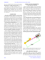
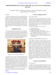
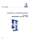
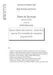
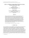
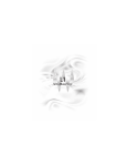
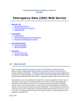
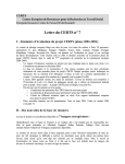
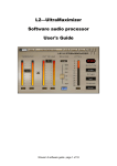
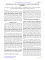
Proceedings of PAC09, Vancouver, BC, Canada
WE6RFP027
PERFORMANCE OF AND UPGRADES TO THE SNS COLLIMATOR
SYSTEMS*
M.A. Plum, A.A. Abdou, L. Jacobs, J. Janney, P.J. Geoghegan, S. McTeer, I. Popova, P. Ferguson,
A. Zhukov, Oak Ridge National Laboratory, Oak Ridge, TN, USA
Abstract
As the Spallation Neutron Source (SNS) beam power is
increased, the collimator systems are becoming
correspondingly more important. The High Energy Beam
Transport (HEBT) transverse collimators are now
routinely used during neutron production. We are in the
process of redesigning the HEBT momentum collimation
system due to problems with gas production from
radiolysis. The Ring collimators are designed for twostage operation but to date they are mainly used in onestage mode. In this paper we will discuss the status, the
operational performance, and upgrades to the collimation
systems.
INTRODUCTION
With a design proton beam power of 1.4 MW delivered
to the neutron spallation target, even beam losses that
amount to of a small fraction of a percent become
significant and cause high activation levels that can
impede accelerator maintenance activities. The SNS
collimator systems [1] are designed to alleviate this
problem by cleaning beam halo and tails that can cause
beam loss, by stripping it off and depositing it into wellshielded enclosures. The SNS has collimator systems in
the HEBT, the Ring, and the Ring-to-Target (RTBT) beam
lines.
In the straight-ahead portion of the HEBT, shortly after
the linac, two collimator systems, each rated for up to
2 kW of beam power, scrape beam tails that may be
present in the transverse phase space. Each system
employs four (top, bottom, left and right), independently
controlled, thin (~25 mg/cm2) carbon scrapers to strip the
tails of the H− beam to H+. Once the beam polarity of the
tails is changed they take a different path through the
magnetic lattice and are absorbed in heavily-shielded
water-cooled cylindrically-symmetric collimators.
Further along the HEBT beam line, at a point of high
dispersion in the 90 deg. arc, a third set of left-right
scrapers intercept the high and low momentum tails of the
beam. In this case the newly created H+ particles are bent
by the arc dipoles in the direction opposite to the main H−
beam, into a short beam line leading to a water-cooled
beam stop capable of absorbing up to 2.5 kW of beam
power.
In the Ring, where the beam species is H+, simple
charge-exchange stripping is no longer an option, so
instead the beam tails are intercepted by thick watercooled tungsten scrapers. The intercepted beam is
___________________________________________
* ORNL/SNS is managed by UT-Battelle, LLC, for the U.S.
Department of Energy under contract DE-AC05-00OR22725
scattered and collected in three water-cooled heavilyshielded cylindrically-symmetric collimators much like
the first two HEBT units, each rated for 2 kW of beam
power.
Finally, in the RTBT, two more collimator systems,
again much like the HEBT units but in this instance
without any scrapers, are used to protect the neutron
spallation target by intercepting any beam particles that
may have distorted trajectories due to extraction kicker
misfires.
EARLY OPERATING EXPERIENCE
During the initial months of low-beam-power
operations the collimator systems were seldom pressed
into service, since they showed negligible improvement in
beam loss. However, as the beam power was increased to
greater than about 300 kW, the HEBT collimator systems
began to yield significant improvements in downstream
beam loss, especially in the injection dump beam line,
where we are most sensitive to beam halo and tails. The
momentum collimator system gave the biggest
improvements, but in April 2008 a pump in the water
cooling system for this collimator failed due to a
concurrent pressure and temperature excursion. A postmortem analysis of the event showed that the over
pressurization was caused by a combination of excessive
beam power and the inability to effectively vent the gases
created by radiolysis. The pump was replaced, but after
discovering the radiolysis gas venting issue the
momentum dump was removed from service since
radiolysis is a problem at any beam power. The
momentum dump is now being re-designed (more on this
later).
After the momentum dump, the next-most-effective
collimators are the upstream HEBT transverse phase
space collimator systems. These systems are now in
routine use. They mainly improve the beam losses in the
injection dump beam line, sometimes by as much as a
factor of 25. They sometimes also improve beam loss in
the HEBT arc. However, there are also times when they
yield very little beam loss improvement, depending on the
quality of the beam from the linac.
The ring collimator system is designed to operate as a
two-stage system. First the beam tails are intercepted by
the scrapers, then the scattered beam is intercepted by the
collimators. However, the system can also be used as a
single-stage system where the scrapers are retracted and
the limiting aperture becomes the collimators themselves.
This mode maximizes the dynamic aperture in the ring,
and this is the mode that we typically use. On the
occasions where the scrapers have been brought into play
we did not observe a significant improvement in beam
Accelerator Technology - Subsystems
T19 - Collimation and Targetry
2847
WE6RFP027
Proceedings of PAC09, Vancouver, BC, Canada
loss, so it is simpler for now to use this system in singlestage mode. As we further increase the beam power, we
anticipate that we will begin using the scrapers.
The purpose of the RTBT collimator systems is to
protect the target from errant beams caused by extraction
kicker misfires, and because there are no adjustable
components, these collimators have been used as
originally planned since the first day of beam to target,
and with the possible exception of radiolysis issues, they
are working well.
RADIOLYSIS
The general definition of radiolysis is the dissociation
of molecules by ionizing radiation. In our case we have
the dissociation of water molecules in the cooling water
system by the ~1 GeV proton beam. All of our collimator
systems absorb the beam power in a water-cooled bed of
stainless-steel balls, and a typical path of a charged
particle hitting the collimator will include some water.
Radiolysis products include hydrogen, hydrogen peroxide,
oxygen and oxygen-containing radicals.
A gas sample taken in December 2008 from the HEBT
transverse collimator cooling water system showed
elevated levels of H2 (0.45% vs. the naturally occurring
0.0002% in air) and depressed levels of O2 (13.2% vs.
20.9% in air). The increased level of H2 is consistent with
the radiolysis process. The depressed level of O2 can be
attributed to the sampling method which introduced air,
possible recombination of hydrogen and oxygen within
the water loop, and the complicated water chemistry.
Particle tracking simulations using MCNPX [2] have
also been performed to estimate the fraction of the beam
power that is deposited in the HEBT transverse collimator
cooling water. The collimator geometry model was
developed according to design drawings, except that the
particle bed was represented by set of coincident cylinders
of steel and water in a volume ratio of about 65%/35%.
The beam source was represented by a disk source
perpendicular to the beam center line, with circular
symmetry on the plane of the disk, from radii 2.3 cm to
5.3 cm, and with the 1 GeV protons directed parallel to
the beam line axis. The energy deposition was calculated
on the basis of one incoming proton and then normalized
to the full beam intensity. This model indicates that for
2 kW of beam power absorbed by a collimator system,
~160 watts is deposited in the water.
Measurements taken in the neutron production target
deionized water cooling systems indicate that ~ 0.4 to 0.5
molecules of hydrogen are produced per 100 eV of energy
absorbed in the water. This, combined with the particle
tracking simulations for the HEBT collimators, allows an
estimate of the hydrogen gas creation to be ~0.5 – 0.7 l/h
for 2 kW absorbed by a HEBT collimator system. This
gas generation rate is comparable to that estimated for the
momentum collimator system. However, gas can be more
effectively vented from the HEBT transverse collimator
cooling water system, and to date it has not caused any
operational problems.
DESIGN OF NEW MOMENTUM
COLLIMATOR SYSTEM
The new momentum collimator system will include an
upgrade of the beam diagnostics between the carbon
scrapers and the beam dump. The initial design had just
beam loss monitors to estimate how much beam was
being scraped and delivered to the dump. As shown in
Fig. 1, the new design will include a beam current
monitor to directly measure the beam power being
delivered to the dump, a beam profile / position monitor
to measure the beam density and position at the entrance
to the dump, a dipole corrector to steer the beam to the
center of the dump, and some additional beam loss
monitors.
The beam dump itself is also being redesigned. Our
goal is to design and build a forced-air-cooled dump to
completely eliminate the complications (e.g. radiolysis,
resin beds, etc) that come with water cooled systems. The
conceptual design calls for removing the water-cooled
portion of the dump (thus leaving a 38 x 38 x 331 cm3
hole in the existing large stack of steel and concrete
shielding) and replacing it with an AJT graphite and AISI
A36 steel assembly. The steel is necessary since the space
available is not sufficient to fully stop a 1.3 GeV proton
beam by using only graphite. Two isometric CAD images
of the new design are shown in Figs. 2-3.
The new dump will be designed for 5 kW – twice the
rating of the old dump. Recirculated air is pumped into
the outer jacket of the new assembly. The reentrant
vacuum window is also cooled by this air. A heat
exchanger, located in the tunnel and cooled by the magnet
water cooling loop, will remove the heat from the dump.
Prof ile
BCM
BLM
BLM
BLM
Dipole
corrector
Figure 1: Momentum dump beam line upgrade. The new
dipole corrector and beam diagnostics are shown in red.
SCRAPER ELECTRONICS
The original design of the three HEBT collimator
systems had just beam loss monitors to estimate how
much beam was intercepted by the scrapers and sent to
the collimators/dump. This is an indirect and inaccurate
Accelerator Technology - Subsystems
2848
T19 - Collimation and Targetry
Proceedings of PAC09, Vancouver, BC, Canada
measurement, and it does not allow one to determine how
much beam is individually intercepted by the scrapers.
WE6RFP027
emitted from other scrapers (in case of several scrapers
being inserted simultaneously).
An example set of waveforms is shown in Fig. 4. Based
on measurements such as this one, the beam power
typically intercepted during neutron production operations
ranges from zero to a few hundred Watts, well within the
design capacity of 2 kW for each collimator system. The
bandwidth of the system is 10 kHz. The electronics are
calibrated by comparing upstream and downstream beam
current monitor signals with the scraper signals, under
carefully controlled conditions.
Figure 2: The new momentum dump including the square
housing that slips inside of the shielding. Recirculated air
is pumped into the outer port and returns on the inner
port.
Figure 4: Example waveforms from the HEBT scraper
electronics. Two of the four scrapers are inserted far
enough to intercept some beam.
FUTURE PLANS
Figure 3: Cross section of the new momentum dump.
Green shows the reentrant vacuum window, brown shows
the graphite, and magenta shows the steel.
These scrapers have now been modified to be
electrically isolated, and the signals caused by secondary
electron emission are collected by electronics interfaced
to the control system and the machine protection system.
The waveforms can be observed in the control room, and
the user can determine how much beam power is
intercepted by each scraper. Also, if the signal level
exceeds a pre-determined threshold (indicating that too
much beam power is being intercepted), the machine
protection system will turn off the beam. This function is
performed in an analog front end that is independent of
software and timing. To mitigate noise issues twisted-pair
type cable is used to carry the reference noise line along
with signal line. The reference signal is amplified
separately and subtracted from the scraper signal. The
electronics also allows the application up to 250 V of
negative HV bias to the scraper plate, thus increasing the
secondary electron emission and rejecting any electrons
We plan to install the new momentum dump in 2010.
Based on the short time we were able to make use of the
original dump, we expect to see immediate improvements
in the downstream beam loss, especially in the injection
dump beam line area.
The ring scrapers have so far been rarely used during
the typical neutron production runs because they have not
significantly improved the overall beam loss in the ring.
However, as we continue to increase the beam power, we
will monitor the performance of this system to determine
how best to use it to control the beam loss. We expect that
it greatest value will be at the highest beam intensities.
REFERENCES
[1] N. Catalan-Lasheras and D. Raparia, PAC’01, p. 3263
(2001). N. Catalan-Lasheras et al., PRSTAB vol. 4
010101 (2001).
[2] L.S. Waters, ed., “MCNPX User’s Manual – Version
2.1.5”, Los Alamos National Laboratory, NM, TPOE83-G-UG-X-00001, Nov. 1999.
Accelerator Technology - Subsystems
T19 - Collimation and Targetry
2849