1
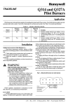
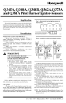
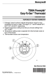
APPLICATION
These gas controls combine a Lite-Rite manual
gas cock, safety shutoff Pilotstat assembly,
millivoltage
automatic valve operator, and optional
gas pressure regulator. They require the use of a
750 mv Powerpile generator (thermopile). The
generator, heated by the pilot burner flame, provides the electrical energy to operate the combination gas control.
A millivoltage
thermostat
with suitable accessory controls completes the automatic control
system for the heating appliance.
Models equipped with the standard pressure
regulator are identified by the suffix letter “A“
WS820A.j
Models without pressure regulator
carry the suffix letter “6” (VS820B). Suffix letter
“C” (VS82OC) identifies models having step
opening type regulators.
Pressure regulators and operator are standardized and interchangeable
on all models in the two
capacity ranges - 225 and 335 cubic feet per
hour.
MANUAL
GAS COCK
\
STANDARD
OUTLET
I,
STRAIGHT
THROUGH
INLET
-4&.-W
A
Fig. 2 -
FLATS (VERTICAL) FOR l-7/8
SIZE PIPE TAPPINGS
I
335,000
PRESSURE REGULATOR ADJUSTMENT
(BENEATH COVER SCREW)
\
,a,,.
Piping pattern and dimensions (in inches) of
VS820.
225,000
LITE-RITE GAS COCK
MANUAL KNOB
INCH WRENCH
I
II2
I
314
I
II2
314
\
PREPARE AND INSTALL PIPE
1. Use new, properly reamed pipe free from chips.
2. Do not thread pipe too far. Valve distortion or
malfunction
may result from excess pipe within
control.
*PILOT
GAS OUTLET.
PRESSURE TAPPING
DIRECTLY BENEATH
PlLOTSTAi
POWER UNIT
LENGTH OF STANDARD
PIPE THREADS (inches)
\
PILOT FLOW ADJ. SCREW
(BENEATH COVER SCREW)
4
NOTE: 24 VOLT VALVE OPERATOR ILLUSTRATED
120 VOLT MODELS FEATURE TWO 36 INCH (914 mm) LEADS
WITH A TERMINAL COVER FOR CONDUIT CONNECTION.
Fig. 1 -
Top view A model. Pressure regulator for “C”
model illustrated at right. (Blank cover plate
(Part No. 392782) is available to convert an
“A” model to a “B” model without pressure
regulator.)
3. Apply moderate amount of good quality dope to
pipe only, leaving two end threads bare. If LP gas installation,
use compound resistant to action of liquified petroleum gases.
PROPER PIPING PRACTICE
2 IMPERFECT
CONTROL
THREAD PIPE RIGHT LENGTH
USE MODERATE
LEAVE 2 END
THREADS BARE
5-83
*TRADEMARK
PRINTEDIN U.S.A.
Form Number 9!%10
0248-l
ResidentialDivision
4. Install drip leg in gas supply pipe. (Fig. 31
3. Connect other end of tubing to pilot burner according to the pilot burner manufacturer’s
instructions.
DROP
I
I
PIPED
WIRING
t
PIPED
GAS
SUPPLY
CAUTION
Never connect these millivoltage controls to
line voltage or to a transformer.
Since the entire system is powered by the
millivoltage generated by the Powerpile
generator, it is important to clean and scrape all
wires before connecting. Solder and tape all
necessary splices using rosin flux to prevent
corrosion. Tighten terminal screws. Total control circuit wiring must not exceed 30 feet of
2-wire 18 gauge cable, or 50 feet of 2-wire 16
gauge cable.
DROP
A
ALL BENDS IN METALLIC
TUBING SHOULD BE SMOOTH.
In
POWERPILE
Fig. 3 - SEDIMENT TRAP (DRIP LEG)
INSTALLATION.
INSTALL CONTROL
1. These controls can be mounted O-90 degrees, in
any direction, from the upright position of the gas
cock knob.
2. Install the control so that gas supply is connected to the end provided with projecting boss for
wrench application. See Fig. 1.
-W
yL-
CONNECT PILOT GAS TUBING
1. Square off and remove burrs from end of tubing.
Bend tubing to desired form for routing to pilot
burner.
A
-k****r-----
A
MUST BE APPROVED SAFETY-CIRCUIT
A
COMBINATION scREw,
TERMINAL (3).
TIGHTEN NUT ONE TURN
BEYOND FINGER TIGHT
TO PILOT BURNER
t
FERRULE BREAKS OFF AND CLINCHES
TUBING AS NUT IS TIGHTENED
2. Slip compression fitting over tubing and slide
out of way. Push tubing into pilot gas tapping on
outlet end of control (Fig. 1) until it bottoms. While
holding tubing all the way in, slide fitting into place
and engage threads - turn until finger tight. Then
use wrench and tighten one turn beyond finger tight.
WIRING.
CONNECT
POWERPILE OPERATOR COIL (INTERNAL WIRING).
PILOTSTAT POWER UNIT COIL (INTERNAL WIRING).
Fig. 4 -Typical
GAS CONTROL BODY
114 INCH 0uicK
Powerpile system wiring diagram.
1. Install Powerpile thermostat, limit control (if required), and Powerpile generator according to
manufacturer’s installation instructions.
2. After Powerpile generator is installed, route
generator lead to Powerpile operator and connect to
Powerpile terminals labeled PP. Make certain jumper
lead from Powerpile operator to safety shutoff
Pilotstat power unit is connected and tightened l/4
turn beyond finger tight.
3. Route wires from control circuit and connect to
the two Powerpile operator terminals labeled TH.
START-UP AND ADJUSTMENTS
GAS COCK SETTINGS (Refer to Fig. I)
The Lite-Rite gas cock knob has three settings:
OFF, prevents any gas from passing through valve
2
to either
main or pilot burner.
PILOT,
which
only (when
generator
ON,
is heated
which
sufficiently
when
LIGHTING
1. Slightly
gas to flow
the system
minutes
for all unburned
LP gas does
open).
main and
for heat.
if at PILOT
to OFF. Wait
gas to vent.
upward
about
naturally.
knob to PILOT,
will stay
one minute
lit after
depress
room temperature
FOR GAS
it
‘A”
The knob must
before
releasing
3. Turn the knob to ON,
5
REMEMBER
and light the pilot burner.
be held down
TEST
knob
m
not vent
2. Turn the Lite-Rite
above
is calling
Lite-Rite
and turn clockwise
burner
to both
PROCEDURE
depress
completely,
or when
to hold valve
gas to flow
position
that
to pilot burner
knob is held depressed
permits
pilot burners
PILOT
permits
gas cock
the pilot
meter
the knob.
PROCEDURE
or by using a pressure
to downstream
standard
burner.
LEAKS
natural
WC outlet
is set at 11 inches.
with
step
With
main
-
DO NOT
burner
OMIT
in operation,
pilot gas tubing connections,
with rich soap and water
gas leakage.
or replace
ADJUST
The
THIS
paint
pipe joints,
increase
and valve gasket lines
solution.
metal
“B”
MODEL
FLAME
pilot flame
(see Fig. 1). Using
screw
(Note:
thread.)
1. With
should
pilot adjustment
cover
envelop
screw
Turn inner adjustment
3/8
(refer
screw
clockwise
n
Adjustment
Replace
m
to
to decrease
slightly
(manometer)
Remove
2. With
to Fig. 1).
or counterclockwise
n
pilot flame.
Be sure to replace
to prevent
fitting
greater
cover
gas
is
turning
force
screw.
burner
is not as specified
PRESSURE
main
burner
pressure
using pressure
Using
CHECK GAS INPUT TO APPLIANCE
a small
burner
combustion.
for size
certain
primary
air supply
is properly
adjusted
instructions
for complete
of appliance
IF METER
CLOCKING
certain
there
meter
other
Other
appliances
than
METHOD
the
to the appliance
being checked.
must
and the pilot
(or their
remain
off,
consumption
deducted
tapping
remove
(Fig.
cover
turn adjusting
1).
screw.
screw
or counterclockwise
gas pressure
to burner.
Replace
performance
ignition
ignite
properly
and all ports
burner
several
cycles
to allow
times
Repeat
remain
30 seconds
regulator
after
pressure,
characteristics.
and without
should
(wait
servo
at step
and flame
allowing
flashback
lit. Cycle
between
to resume
appliance
step
to cool.
CHECKOUT
IS USED
through
is required,
burner
should
action.)
is no gas flow
by
(manometer)
pressure
to increase
burner
to orifice,
if provided.
Make
extinguished
Burner
pressure
Make
Follow
manufacturer
or manufacturer’s
orifice
input
manifold
screw.
observing
burner
check
burner
gauge
screwdriver,
m
3. Check
on
or check
to decrease
cover
IMPORTANT
input rating stamped
REGULATOR
to downstream
clockwise
n
to main
by the appliance
on LP gas storage
operating,
gas meter,
2. If adjustment
used.
regulator
clocking
connected
orifice(s)
(Fig. 1).
burner
MODELS)
1. With
3/S TO 112 INCH
of appliance,
check
tank.
PROPER
nameplate
gauge
tapping
gas leakage.
1°C”
recommended
regulator)
pressure
pressure
operating,
readjust
STEP-OPENING
Do not exceed
connect
pressure.
manufacturer,
after
(no pressure
off,
to downstream
3. If pressure
to increase
cover
possible
burner
main
manifold
mto
PROCEDURE
main
to l/2
clockwise
adjustment
the meter
screw
and may require
than
LP gas
is required,
the gasket.
inch of the tip of the thermocouple.
NOTE:
and the standard
turn adjusting
to burner.
plastic
1). The
set at 3.5
If adjustment
or counterclockwise
pressure
Bubbles indicate
(Fig.
2.
cover
screwdriver,
To stop leak, tighten joints and screws
PILOT
decrease
TEST
gas
(manometer)
is factory
pressure,
regulator)
by clocking
tapping
inches
proceed
pressure
gauge
gas model
model
2. Remove
WARNING
(with
input to main burner
connected
and set the thermostat
to turn on main
MODEL
1. Check
from
Put the system
into operation
complete
cycle
to be sure all controls
properly.
Make
certain
flow
reading).
flame
3
to main
burner
is extinguished.
and observe
the Pilotstat
within
2-l/2
through
function
unit shuts
minutes
after
off gas
pilot
OPERATING INSTRUCTIONS
HOMEOWNER
PILOT GOES OUT WHEN LITE-RITE KNOB IS
RELEASED
1. Check pilot flame adjustment. See page 3.
‘MPORTANT
Follow the operating instructions provided by the
manufacturer of your heating appliance. The information below will be of assistance in a typical control application, but the specific controls used and
the procedures outlined by the manufacturer of
your appliance may differ, requiring special
instructions.
2. Check the Powerpile generator connection to
Pilotstat power unit (Fig. 1). This is an electrical connection and must be clean and secure. Also check the
Powerpile generator connections to the valve operator.
3. If power unit still does not hold in, use the W720
Systems Tester to obtain the exact open and closed
circuit output voltages of the generator. Compare with
the Acceptable Range Charts in W720 manual or Gas
Controls Service Handbook. Next check resistance of
Pilotstat power unit.
LITE-RITE KNOB SETTINGS
Refer to GAS COCK SETTINGS,
If W720 or other meter is not available, first replace
generator. If this does not correct the condition
replace power unit (adjacent to gas cock knob - see
Fig. 1). Turn off gas supply to appliance (at service
cock or meter) and remove power unit with wrench.
Install and tighten new power unit. Turn on gas supply
and check for gas leakage.
COMPONENT
FOR THE
page 2.
TO LIGHT PILOT AND TURN ON MAIN BURNER
Follow PILOT LIGHTING PROCEDURE, page 3.
TO SHUT OFF
1. For TEMPORARY situations: Main burner can be
shut off by turning clockwise m
from ON to
PILOT. Pilot will remain lit - ready for return to normal service without relighting. (This is the recommended summer shutdown position.)
AND PARTS REPLACEMENT
The automatic valve operators and servo regulators
may be added in the field, or replaced in service
maintenance. (Model number is stamped on side of
component.) Complete instructions are furnished with
the component.
2. For COMPLETE SHUTDOWN: Slightly depress
Lite-Rite knob when at PILOT position and turn
clockwise m
to OFF Both pilot and main burner
now are shut off.
REPLACEMENT VALVE OPERATOR: VS824A.
AUTOMATIC SAFETY SHUTOFF
The automatic safety shutoff valve blocks gas flow
to the main burner and pilot burner if the pilot flame
goes out or becomes too small for adequate ignition.
REPLACEMENT SERVO PRESSURE REGULATOR:
V5306 standard and V5307 step opening type.
Either models are field addable to “B” models.
VS820 “A” or “C” models can be converted to
“B” models by removing the pressure regulator and
applying a blank plate and gasket, Pt. No. 392782.
If safety shutoff occurs, check pilot flame after
relighting and adjust if necessary. See ADJUST
PILOT FLAME, page 3. If shutoff reoccurs, contact
your local dealer or gas utility to correct condition
causing shutdown.
REPLACEMENT PARTS:
Pilotstat power unit (750 mv) - 392395.
Compression fitting for pilot tubing connection386449.
Pilot gas filter - 391158.
ELECTRICAL DATA:
Pilotstat Power Unit - Hold-in 15 ma maximum;
dropout 10.5 to 4.5 ma; resistance 11 ohms.
Valve Operator - Pull-in 65 ma maximum; coil
resistance 2 ohms.
This material is proprietary to Honeywell Limited and shall not be reproduced, copied or used in any manner without prior written consent of
Honeywell Limited.
HONEYWELL
l
740 Ellesmere
Road
l
Scarborough
l
Ontario
MlP
2V9