1
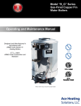
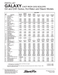
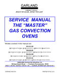
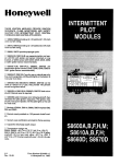
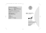
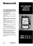
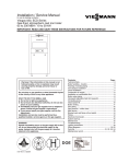
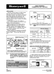
Q345A, Q348A, Q348B, Q362A,Q373A
and Q381A Pilot Burner/Igniter-Sensors
Application
These pilot burner/igniter-sensors provide pilot flame
ignition and sensing in intermittent pilot systems. They
consist of a target type pilot burner with a combination
spark igniter and flame sensor mounted in place of the
thermocouple.
Installation
WHEN INSTALLING THIS PRODUCT…
1. Read these instructions carefully. Failure to
follow instructions can damage product or cause a
hazardous condition.
2. Check ratings given in instructions and on
product to make sure product is suitable for your
application.
3. Make sure installer is a trained, experienced
service technician.
4. After completing installation, use these
instructions to check out product operation.
WARNING
FIRE OR EXPLOSION HAZARD
CAN CAUSE PROPERTY DAMAGE,
SEVERE INJURY, OR DEATH.
Follow these warnings exactly:
1. Disconnect power supply before wiring
to prevent electrical shock or equipment
damage.
2. To avoid dangerous accumulation of fuel
gas, turn off gas supply at appliance service
valve before starting installation and
perform Gas Leak Test after completion of
installation.
3. Do not bend pilot tubing at the control or
pilot after compression nut has been
tightened. Gas leakage at the connection may
result.
Follow appliance manufacturer instructions if available; otherwise, use instructions provided below.
LOCATION
1. Position pilot burner/igniter-sensor for easy
access and observation. In replacement applications,
replace pilot burner/igniter-sensor with an identical unit
and position new pilot burner/igniter-sensor in the same
location and orientation as the original one.
Fig. 1—Mount pilot burner/igniter-sensor on
main burner.
PILOT BURNER/IGNITER-SENSOR
MUST BE RIGIDLY POSITIONED
RELATIVE TO MAIN BURNER
M3271
Fig. 2—Location of pilot burner/igniter-sensor.
PILOT BURNER/
IGNITERSENSOR
JUST RIGHT
PILOT BURNER/
IGNITERSENSOR
TOO LOW
PILOT BURNER/
IGNITERSENSOR
TOO HIGH
IGNITION FLAME
JUST MISSES
MAIN BURNER
IGNITION
FLAME WILL
IMPINGE ON
MAIN BURNER
MAIN BURNER
FLAME WILL
IMPINGE ON
IGNITIONSENSOR
M3273
2. Mount pilot burner/igniter-sensor on main burner.
Mounting surfaces other than the main burner may shift,
bend, or warp as furnace expands and contracts while
operating. See Fig. 1.
3. Mount pilot burner/igniter-sensor so the pilot flame
remains properly positioned with respect to the main
burner flame. See Fig. 2.
4. Supply pilot flame with ample air free of
combustion products.
5. Do not impinge pilot flame on adjacent parts.
Do not impinge main burner flame on pilot burner/
igniter-sensor.
6. Do not expose pilot flame to falling scale, which
could impair main burner ignition.
7. Do not expose pilot burner/igniter-sensor to main
burner rollout while igniting or extinguishing.
8. Do not expose pilot flame to drafts that push or
pull pilot flame away from the igniter-sensor.
NOTE: The Q381A Pilot Burner/Igniter-Sensor is for
horizontal mounting only. Mounting bracket must
remain vertical.
G. S. • Rev. 7-93 • ©Honeywell Inc. 1993 • Form Number 60-0653—8
2. Connect one end of the ignition cable to stud
terminal on igniter-sensor using 1/4 in. [6 mm] diameter snap-spring or cage-clips on cable ends.
3. Connect the other end of the ignition cable to the
igniter terminal on ignition module.
4. Use ceramic or plastic standoff insulators as necessary to prevent cable from contacting metal surfaces.
CONNECT PILOT GAS TUBING
1. Cut tubing to desired length and bend as necessary
for routing to pilot burner/igniter-sensor. Do not make
sharp bends or deform tubing. Do not bend tubing at
control after compression nut has been tightened
because this can result in gas leakage at connection.
2. Square off and remove burrs from end of tubing.
3. Push tubing into compression nut clearance hole
until tubing bottoms.
INSTALL BLEED GAS TUBE (optional)
1. Route bleed tube from bleed tap on gas control to
the pilot burner/igniter-sensor.
2. Push clip into place. See Fig. 4.
3. Insert bleed gas tube until 3/8 in. [10 mm] to
tubing is above pilot burner/igniter-sensor bracket. Tip
of bleed gas tube must not extend into pilot flame.
NOTE: When replacing a control, cut off old
compression fitting and replace with new
compression fitting provided with new pilot
burner. Never use old compression fitting because it
may not provide a gas-tight seal. See Fig. 3.
Fig. 3—Always use new compression fitting.
Fig. 4—Install bleed gas tube.
THIS DIMENSION SHOULD
BE MAXIMUM OF 3/8 INCH
[9.5 mm] WHEN BLEED
TUBE IS IN FINAL
POSITION.
PILOT BURNER BODY
ON BRACKET OF PILOT
BURNER/IGNITER-SENSOR
COMPRESSION FITTING
BREAKS OFF AND CLINCHES
TUBING AS NUT IS TIGHTENED
BLEED TUBE CLIP
1/8 IN. STEEL TUBING
TIGHTEN NUT ONE TURN
BEYOND FINGER TIGHT
TO GAS CONTROL
M1261
M3296
4. While holding tubing all the way in, engage threads
and turn until finger tight.
5. Using a wrench, turn compression nut one turn
beyond finger tight. Do not overtighten.
6. Connect other end of tubing to gas control
according to gas control manufacturer instructions.
Startup and Checkout
PERFORM GAS LEAK TEST
WARNING
WIRE IGNITER-SENSOR
The igniter-sensor must be mounted on the burner.
Connect the control module ground wire to one of the
igniter-sensor mounting screws to complete the system
grounding.
Connect ground wire as follows:
1. Use 221° F [105° C] minimum thermoplasticinsulated wire for the ground leadwire (asbestos
insulation is not acceptable).
2. A male 1/4 in. [6 mm] quick-connect terminal is
provided on Honeywell ignition modules. Fasten female
quick-connect to wire end at ignition module.
3. Strip other end and fasten under igniter-sensor
mounting screw.
4. If necessary, use shield to protect lead from radiant heat of burner.
5. The pilot burner serves as the grounding area for
the flame signal. Run lead from pilot burner to the
common ground selected.
Connect the ignition cable as follows:
1. The high tension ignition cable must conform to
applicable local or national standards.
FIRE OR EXPLOSION HAZARD
CAN CAUSE PROPERTY DAMAGE,
SEVERE INJURY, OR DEATH.
Check for gas leaks with soap and water solution any time work is done on a gas system.
Gas Leak Test:
1. Ensure that gas supply is turned on at the appliance
service valve.
2. Paint pipe connections upstream of pilot burner
with rich soap and water solution. Bubbles indicate gas
leak.
3. If leak is detected, tighten pipe connections.
4. Set thermostat to call for heat to light main burner.
5. With main burner in operation, paint pipe joints
(including adapters) and gas control inlet and outlet with
rich soap and water solution.
6. If another leak is detected, tighten adapter screws,
joints, and pipe connections.
7. Replace part if leak cannot be stopped.
2
Fig. 5—Igniter-sensor tip must be in pilot flame.
Fig. 6—Proper shielding of pilot flame.
3/8 TO 1/2 INCH
[10 TO 13 mm]
PROPER FLAME
ADJUSTMENT
IGNITER-SENSOR
Q373A
PROPER FLAME
ADJUSTMENT
3/8 TO 1/2 INCH
[10 TO 13 mm]
TYPICAL
SHIELD
M1273
IGNITER-SENSOR
Q345A, Q348A-B, Q362A AND Q 381A
J Set the thermostat to call for heat.
J Watch the pilot burner during the ignition sequence.
M3777
See if:
• Ignition spark continues after the pilot is lit.
• The pilot lights and the spark stops, but main
burner does not light.
• S8600B,H; S86H only: The pilot lights, the spark
stops and main burner lights, but the system locks
out.
J If so, assure adequate flame current as follows:
• Turn off furnace at circuit breaker or fuse box.
• Clean the flame rod with emery cloth.
• Make sure electrical connections are clean and tight.
Replace damaged wire with moisture-resistant
no. 18 wire rated for continuous duty up to
221° F [105° C].
• Check for cracked ceramic insulator, which can
cause short to ground, and replace pilot burner/
igniter-sensor if necessary.
• At the gas control, disconnect main valve wire
from the TH or MV terminal.
• Turn on power and set thermostat to call for heat.
The pilot should light but the main burner will
remain off because the main valve actuator is disconnected.
• Check the pilot flame. Make sure it is blue, steady
and envelops 3/8 to 1/2 in. [10 to 13 mm] of the
flame rod. See Fig. 7 for possible flame problems
and their causes.
• If necessary, adjust pilot flame by turning the pilot
adjustment screw on the gas control clockwise to
decrease or counterclockwise to increase pilot
flame. After adjustment, always replace pilot
adjustment cover screw and tighten firmly to
assure proper gas control operation.
• Set thermostat below room temperature to end call
for heat.
J Recheck ignition sequence as follows:
• Reconnect main valve wire.
• Set thermostat to call for heat.
• Watch ignition sequence at burner.
• If spark still does not stop after pilot lights, replace
ignition module.
• If main burner does not light or if main burner
lights but system locks out, check module, ground
wire, and gas control as described in control
module instructions.
ADJUST PILOT FLAME
The pilot flame should envelop 3/8 to 1/2 in.
[10 to 13 mm] of the igniter-sensor tip. See Fig. 5. To
adjust pilot flame:
1. Turn off system by setting thermostat below
temperature to call for heat.
2. Disconnect lead to MV terminal on gas control.
3. Light pilot by setting thermostat to call for heat.
4. Remove pilot adjustment cover screw from gas
control.
5. Turn inner pilot adjustment screw clockwise to
decrease or counterclockwise to increase pilot flame.
6. Always replace pilot adjustment cover screw and
tighten firmly after completing adjustment to assure
pro-per operation.
Service
WARNING
FIRE OR EXPLOSION HAZARD
CAN CAUSE PROPERTY DAMAGE,
SEVERE INJURY, OR DEATH.
Perform Gas Leak Test anytime work is done to
the system.
PILOT OUTAGE
1. If pilot flame goes out during ignition, but is
pro-perly adjusted, recheck mounting and location
instructions in Location section.
2. Refer to ignition module instructions to check
wiring between igniter-sensor and ignition module or
between gas control and ignition module.
3. If all mounting and location instructions are followed but pilot continues to go out, construct shielding
to protect pilot flame from main burner ignition and
extinction and drafts. See Fig. 6.
4. Check pilot and main burner lightoff.
3
60-0653—8
Fig. 7—Example of unsatisfactory pilot flames.
APPEARANCE
APPEARANCE
SMALL BLUE FLAME
SMALL BLUE FLAME
CAUSE
CHECK FOR LACK OF GAS FROM:
• CLOGGED ORIFICE FILTER
• CLOGGED PILOT FILTER
• LOW GAS SUPPLY PRESSURE
• PILOT ADJUSTMENT AT MINIMUM
LAZY YELLOW FLAME
LAZY YELLOW FLAME
CHECK FOR LACK OF AIR FROM:
• DIRTY ORIFICE
• DIRTY LINT SCREEN, IF USED
• DIRTY PRIMARY AIR OPENING,
IF THERE IS ONE
• PILOT ADJUSTMENT AT MINIMUM
WAVING BLUE FLAME
WAVING BLUE FLAME
CHECK FOR:
• EXCESSIVE DRAFT AT PILOT
LOCATION
• RECIRCULATING PRODUCTS
OF COMBUSTION
NOISY LIFTING BLOWING FLAME NOISY LIFTING BLOWING FLAME
CHECK FOR:
• HIGH GAS PRESSURE
HARD SHARP FLAME
HARD SHARP FLAME
THIS FLAME IS CHARACTERISTIC
OF MANUFACTURED GAS
CHECK FOR:
• HIGH GAS PRESSURE
• ORIFICE TOO SMALL
M3778
CHECK IGNITION CABLE
1. Assure that ignition cable is not in contact with
metal surfaces.
2. Assure that ignition cable is not more than
3 feet [1 m] long.
3. Assure connections to the ignition module stud
terminal and the igniter-sensor are clean and tight.
4. Check electrical continuity of ignition cable.
CHECK GROUNDING
1. If ground is poor or erratic, safety shutdown will
occur. Therefore, if nuisance shutdowns are reported,
check the ground precautions in Wire Igniter-Sensor
section.
Home and Building Control
Honeywell Inc.
1985 Douglas Drive North
Golden Valley, Minnesota 55422
2. If leadwire is damaged or deteriorated, use
no. 14 to 18 gauge, moisture-resistant, thermoplastic,
insulated wire with 221° F [105° C] minimum rating as
replacement.
3. Excessive temperature at the ceramic flame rod
insulator will permit electrical leakage to ground.
a. If bracket is bent, bend it back to correct
position.
b. If insulator is cracked, replace pilot burner/
igniter-sensor.
TEST SAFETY LOCKOUT
Refer to appliance manufacturer instructions to test
for proper safety lockout times.
Home and Building Control
Honeywell Limited—Honeywell Limitée
740 Ellesmere Road
Scarborough, Ontario
M1P 2V9
Helping You Control Your World
QUALITY IS KEY
Printed in U.S.A.