1
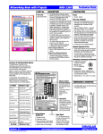
Gas Monitoring Alarm System
Manning GM-1
Instruction and Installation Manual
07/09
Release D Draft
Honeywell Confidential & Proprietary
This work contains valuable, confidential, and proprietary information. Disclosure, use
or reproduction outside of Honeywell Inc. is prohibited except as authorized in writing.
This unpublished work is protected by the laws of the United States and other countries.
Manning GM-1 Gas Monitoring Alarm System 19546 GM1 07/09 REVD Copyright © 2009 Honeywell Analytics. All Rights Reserved.
1
Notices and Trademarks
Copyright 2009 by Honeywell International Inc.
Release D July 2009
While this information is presented in good faith and believed to be accurate, Honeywell disclaims the implied
warranties of merchantability and fitness for a particular purpose and makes no express warranties except as may
be stated in its written agreement with and for its customers.
In no event is Honeywell liable to anyone for any indirect, special or consequential damages. The information and
specifications in this document are subject to change without notice.
Manning is a registered trademark of Honeywell International Inc.
Other brand or product names are trademarks of their respective owners.
Honeywell Analytics
405 Barclay Blvd.
Lincolnshire, IL 60069
USA
1-800-538-0363
Manning GM-1 Gas Monitoring Alarm System 19546 GM1 07/09 REVD Copyright © 2009 Honeywell Analytics. All Rights Reserved.
2
About This Document
World Wide Web
The following Honeywell web sites may be of interest.
Honeywell Organization
WWW Address (URL)
Corporate
www.honeywell.com
Honeywell Analytics
www.honeywellanalytics.com
Manning Gas Detection
www.manningsystems.com
Telephone
Contact us by telephone at the numbers listed below.
Organization
Phone Number
United States
Honeywell Analytics Inc.
1-800-538-0363
1-913-712-5576
1-913-712-5580 Fax
Canada
Honeywell Analytics Inc.
1-888-749-8878
Europe
Honeywell PACE
+44 (0)1202 676161
Asia Pacific
Honeywell Asia Pacific Inc.
+82 (0)2 2025 0307
Middle East
Honeywell Analytics Inc.
+971 4 3458 338
Sales Information
Contact us at [email protected]
Symbol Definitions
The following table lists those symbols used in this document to denote certain conditions.
Symbol
Definition
ATTENTION: Identifies information that requires special consideration.
CAUTION: Indicates a potentially hazardous situation which, if not avoided, may result
in minor or moderate injury. It may also be used to alert against unsafe practices.
CAUTION symbol on the equipment refers the user to the product manual for
additional information. The symbol appears next to required information in the manual.
WARNING: Indicates a potentially hazardous situation, which, if not avoided, could
result in serious injury or death. WARNING symbol on the equipment refers the user to
the product manual for additional information. The symbol appears next to required
information in the manual.
CAUTION
indicates a situation which, if not avoided, may result in equipment or work (data) on
the system being damaged or lost, or may result in the inability to properly operate
the process.
Manning GM-1 Gas Monitoring Alarm System 19546 GM1 07/09 REVD Copyright © 2009 Honeywell Analytics. All Rights Reserved.
3
Contents
Serial number:
Section
Title
Page
1
System Description
5
2
Installation
7
3
Operation
10
4
Limited Warranty
13
Introduction
This manual has been prepared to help in the use and installation of the Manning GM-1 Gas Monitoring Alarm
System. This manual will convey the operating details of the alarm system, ensure proper installation, and
demonstrate start-up and routine maintenance procedures.
ATTENTION: This manual must be carefully followed by all individuals who have or will have the
responsibility for using or servicing the Manning GM-1 alarm system. Warranties made by Honeywell
Analytics with respect to this equipment will be voided if the equipment is not used and serviced in accordance
with the instructions in this manual. If in doubt about a procedure, please contact Honeywell Analytics before
proceeding.
Manning GM-1 Gas Monitoring Alarm System 19546 GM1 07/09 REVD Copyright © 2009 Honeywell Analytics. All Rights Reserved.
4
1
System Description
The Manning GM-1 is designed to accept a single
4/20 mA current input signal, plus provide a regulated
24 VDC supply to operate all sensors manufactured by
Honeywell Analytics.
The Manning GM-1 is housed in a rugged 14 gauge
gasketed steel enclosure. Behind the clear plexiglass
window is a 20-segment vertical LED bargraph display
which gives a visual indication of the gas
concentration.
The unit has warning and alarm level indications on the
front panel, and warning and alarm relays allowing the
user to incorporate functions such as ventilation
control, remote horns, security system monitoring, and
automatic shutdown.
Designed to be highly reliable when properly installed,
all relays are energized during normal operation, and a
sensor fault monitoring circuit will indicate a fault and
trip a dedicated fault relay if the signal falls below
1.4 mA.
The unit has an audible horn which will sound if an
alarm or fault condition is detected. The silence switch
will silence the horn until the next event. If an alarm
condition initiates the horn, the horn will clear
automatically when the alarm relay clears.
The unit has a power-up delay feature that places all
outputs in normal conditions for one minute to allow for
sensor stabilization.
The Manning GM-1 will support all of Manning
sensors, including oxygen, which requires a downscale alarm.
All components that are in contact with voltages above
40 volts are UL listed, including the enclosure.
Note: The Manning GM-1 is for use in
non-classified areas only.
Manning GM-1 Gas Monitoring Alarm System 19546 GM1 07/09 REVD Copyright © 2009 Honeywell Analytics. All Rights Reserved.
5
1
System Description continued
System Specifications
Electrical Power: 120 VAC, 50/60 Hz at 0.35 amp
(230 VAC 50/60 Hz is available as an option)
Signal input: 4/20 mA
DC Power available for sensors: Heavy-duty
internal 24 VDC, 1 amp maximum regulated supply
Enclosure: 14 gauge steel, gasketed, 10" high x 8"
wide x 4" deep, NEMA 1 rated enclosure with
plexiglass window
Weight: 11 lbs.
Operating Ambient Temperature range: 0o F to
+120o F
Display: 20-segment LED bargraph
Operating Humidity: 5-95% Relative Humidity, noncondensing
Light Outputs and Relays:
Options: Down-scale Alarm for oxygen
Alarm Light and Relay
Push-button Controls:
•
Setpoint field adjustable
Silence — Silences internal horn
•
Alarm Light and Relay independently latchable
by board mounted DIP switch
•
10 second on delay, 2 second off delay
Reset — Clears signal, latched functions, and
relays. If warning, alarm, or fault condition
exists, indications will return after a short time
delay.
Warning Light and Relay
•
Setpoint field adjustable
•
Warning Light and Relay are NOT latchable
•
10 second on delay, 2 second off delay
Note: The Manning GM-1 is for use only in
non-classified areas.
Fault Light and Relay
•
Setpoint NOT adjustable — all mA signals below
1.4 mA will initiate fault output
•
Fault Light and Relay always latch
•
10 second on delay
Note: All relays are normally energized
and monitored by individual LEDs for
ease of troubleshooting
Relay Ratings: 3 amps at 24 VDC or 120 VAC
Form C providing NO (normally open) or NC
(normally closed) option
Manning GM-1 Gas Monitoring Alarm System 19546 GM1 07/09 REVD Copyright © 2009 Honeywell Analytics. All Rights Reserved.
6
2
A
Installation
Locating the Manning GM-1
When unpacking the unit, inspect all boxes and
contents for shipping damage. If any screws or
other metal parts are missing, these must be found
to ensure that the printed circuit boards will not be
damaged when power is applied.
Figure 1: Mounting dimensions for the Manning GM-1
Gas Monitoring Alarm System
6"
5/16"
The control unit is designed to be mounted on a
solid (non-vibrating) wall through four holes in the
two mounting flanges. While the physical location
must be determined in part by local conditions, it is
important to consider the following:
Gas Monitor
CAUTION
•
Protect the Manning GM-1 from rain, snow,
water sprays, cleaning crews, and physical
damage.
•
Mount the unit on a solid wall (nonvibrating) at eye level for convenience in
taking readings, servicing, etc.
•
The Manning GM-1 is NOT explosion proof.
DO NOT MOUNT in a hazardous
atmosphere.
•
Operating temperature for the Manning
GM-1 is 0o F to +120o F.
•
Pre-punched holes are provided in the
bottom of the enclosure for cable access.
DO NOT drill holes in the top of the cabinet
as this will void the warranty.
•
If hole drilling is required, be sure to remove
all metal filings.
•
Mounting dimensions are included in Figure 1.
Manning GM-1 Gas Monitoring Alarm System 19546 GM1 07/09 REVD Copyright © 2009 Honeywell Analytics. All Rights Reserved.
Manning GM-1
10 3/4"
Reset
24 1/4"
Silence
7
2
B
Installation continued
Wiring
Electrical wiring must comply with all applicable
codes. Plant equipment that may be involved and
operating conditions should be discussed with local
operating personnel to determine if any special
needs should be taken into account.
Relay Wiring:
All three relays have Form C, dry contacts. Any
required power source must be within the 3 amp
rating and fused or current limited to keep from
damaging the contacts.
•
Relay wiring must be run in separate conduit
from the sensor cable if the relay circuit is AC.
Nearly all start-up problems are due to improper
wiring or monitor configuration. Please follow these
guidelines carefully. Figure 2 presents a wiring
diagram for the Manning GM-1.
Sensor Wiring:
•
See sensor manual for proper sensor cable.
AC Power Wiring:
•
See sensor manual for proper sensor location.
•
Use only stranded cable for AC power,
relay outputs, and sensor input cables.
•
Never run AC circuits in the same conduit as
the sensor cable.
•
The units must have a proper third wire
ground for safety and sensor shielding.
Be sure to follow local codes.
Note: Relays are energized in a non-alarmed
condition so that a power loss in the Manning GM1 will result in an alarm.
•
All AC cables must be kept away from the
incoming sensor cables, i.e., do not put AC
cables inside conduit containing sensor
cables.
•
Keep all wiring away from variable speed
drives and SCR control units to minimize
electrical noise exposure.
•
Electrical Power: 120 VAC, 50/60 Hz, 0.35
amps.
•
Electrical power ground: The unit must be
properly grounded.
Risk of electric shock.
Manning GM-1 Gas Monitoring Alarm System 19546 GM1 07/09 REVD Copyright © 2009 Honeywell Analytics. All Rights Reserved.
8
2
Installation continued
Figure 2: Wiring diagram for the Manning GM-1 Gas Monitoring Alarm System
WARNING
ADJUST
TP
+20V
ALARM
ADJUST
BOT TOP
7
TP
WARNING
TP
ALARM
TP
SIG
ALARM
RELAY
FAULT
RELAY
TP
CURRENT
WARNING
RELAY
DRAW
TP
GND
1
6
+
C11
+
+
FUSE RATING
250V 1.0 AMP
SHLD GND
L
N
120 VAC
NO
C
NC
WARNING
RELAY*
NO
C
NC
NO
ALARM
RELAY*
C
+ 24
SIG
NC
FAULT
RELAY*
MODEL G/M
MAINBOARD REV D
*Relay rating 3 amp. User must fuse to protect.
Note: Green wire earth ground must be connected to grounding
stud marked
Bare wrap— to "SHLD" terminal of sensor
Black— to "GND" terminal of sensor
Risk of electrical shock.
Red— to "+24" terminal of sensor
White— to "SIG" terminal of sensor
Manning GM-1 Gas Monitoring Alarm System 19546 GM1 07/09 REVD Copyright © 2009 Honeywell Analytics. All Rights Reserved.
Potential hazard.
9
3
A
Operation
Display Panel
A 20-segment Bargraph Display indicates the gas
concentration level. The bottom LED is always lit to
indicate power to the display.
The Warning LED indicates the warning level as
determined by the warning setpoint has been
exceeded. The Warning LED and Warning Relay
operate together and never latch.
The Alarm LED indicates the alarm level as
determined by the alarm setpoint has been
exceeded. The Alarm LED and Alarm Relay are
independently latchable or non-latchable as
determined by the DIP switch on the main board.
Standard factory settings are to latch the LED and
not latch the relay.
C
DIP Switch Setting
The two position DIP switch in the center of the bottom
board controls the latching of the alarm light and alarm
relay. Switch 1 (left) controls the alarm relay. Switch 2
(right) controls the alarm light. Putting the switch in the
on (up) position will latch the corresponding function.
Putting the switch in the off (down) position will cause
the corresponding function to be not latched (see
Figure 3).
This allows the alarm condition to remain activated if
desired even if the gas concentration goes back to
below the setpoint.
Figure 3: Warning adjustment and DIP switch settings
The Power LED indicates power to the monitoring
unit. This LED will flash during the one minute
power up delay indicating that all relays are held in
the normal condition to allow for sensor stabilization
during power up.
The Fault LED indicates a signal input of less than
1.4 mA (0.14 volts) at TP Sig. The Fault LED and
Fault Relay always latch.
WARNING
ADJUST
Reset and Silence Switches
TP
SIG
WARNING
RELAY
1
2
SW1
AA
ALARM
RELAY
FAULT
RELAY
6
+
C11
+
+
FUSE RATING
250V 1.0 AMP
SHLD GND
L
Pushing the Silence switch will silence the horn on
the bottom of the Manning GM-1 until the next event
occurs. The horn is triggered by a fault or an alarm
condition. The horn will clear itself if the alarm and
fault relay clear. A warning condition does not
trigger the horn.
TP
ALARM
CURRENT
Pushing the Reset switch will reset the fault light,
fault relay, alarm light, and alarm relay. If either
condition still exists, the appropriate light and relay
will return to its tripped state after a time delay.
1
BOT TOP
TP
WARNING
TP
B
ALARM
ADJUST
TP
+20V
DRAW
TP
GND
7
N
NO
120 VAC
C
NC
NO
WARNING
RELAY*
C
ALARM
RELAY*
NC
NO
C
+24
SIG
NC
FAULT
RELAY*
MODEL G/M
MAINBOARD REV D
0.4 - 2.0 V
VDC
Black
-
Warning adjust pot
DIP switches on
bottom of board
Red
+
Do Not Adjust!
Factory set pots
Risk of electrical shock.
Potential hazard.
Manning GM-1 Gas Monitoring Alarm System 19546 GM1 07/09 REVD Copyright © 2009 Honeywell Analytics. All Rights Reserved.
10
3
D
Operation continued
Signal and Setpoints
The voltage between TP Gnd and TP Sig indicates
the current signal received from the sensor. The
normal range is 0.4 volts to 2.0 volts, which
corresponds with 4/20 mA. This manual will use the
voltage at TP Sig to describe the input signal. When
this signal exceeds the voltage at TP Warning or TP
Alarm, the warning or alarm function will take place.
The warning setpoint is user adjustable by looking at
the voltage on TP Warning and adjusting the warning
adjust pot until the desired setpoint is reached (see
Figure 3). The alarm adjust pot and TP Alarm function
the same way.
The warning and alarm setpoints are factory adjusted
as indicated on the data sheet included with your
GM-1. Never adjust these setpoints outside the range
of 0.4 to 2.0 volts. Contact Honeywell Analytics if you
have any questions or want help in determining
setpoints for your particular sensor and application.
After setpoint adjustment always expose sensor to
the gas being monitored and verify that the warning
and alarm lights trigger at the desired concentration
as displayed by the bargraph.
E
Start-Up Procedures
Before applying power, make a final check of all
wiring for continuity, shorts, grounds, etc. It is usually
best to disconnect external alarms and other
equipment from the unit until the initial start-up
procedures are completed.
After power-up, allow 24 hours for the system to
stabilize before testing the sensor. Because sensors
are normally located at a distance from the
monitoring unit, the test time required and accuracy
of the response checks will be improved if two
people perform the start-up procedures and use
radio contact.
F
Troubleshooting
The Fault Light and Fault Relay always latch when a
fault condition is detected. After the condition is
corrected the Reset switch must be pressed to clear
the Fault Light and Fault relay.
The unit will indicate a fault if the signal is less than
0.14 volts at TP Sig.
Some Manning sensors are configured to send a
signal of 0.05 volts at TP Sig if a sensor fault exists. If
TP Sig = 0.05 volts, this indicates a properly wired
sensor is in a fault condition. Proceed to investigate
the sensor.
If TP Sig = 0.00 volts, this indicates no signal from the
sensor. Check for correct wiring or loose connections
between the sensor and monitoring unit.
Each relay has a green LED in series with its coil. If
this LED is on, this indicates that the relay is
energized and contacts will be in the normal position.
If this LED is off, the contacts will be in the tripped
condition.
Power supply voltages should be checked at
TP +20V on the display board and at +24 on
the sensor input terminal block (see Figure 4).
Both points should be DC Volts as labeled.
The total sensor current draw can be checked by
looking at the voltage between the two TP Current
Draw test points. 1.0mV corresponds to 10 mA, and
50.0mV corresponds to 500mA, etc. Compare this
reading with the current draw expected for the
sensor you are using (see appropriate sensor
manual).
If questions arise, call Honeywell Analytics.
Start-Up Test: One person exposes the sensor to a
small amount of the gas that is being monitored. The
second person stays at the monitoring unit to
determine that the sensor, when exposed to the
target gas, is connected to the proper input,
responds, and causes appropriate alarm functions.
Manning GM-1 Gas Monitoring Alarm System 19546 GM1 07/09 REVD Copyright © 2009 Honeywell Analytics. All Rights Reserved.
11
3
Operation continued
Maintenance
G
Replacement Parts
H
The Manning GM-1 is designed for long life and high
reliability. Honeywell Analytics recommends
checking signal voltages monthly and logging them
on the data sheet included with your Manning GM-1.
Additionally, the sensor being monitored should be
exposed to the target gas on a monthly basis while
all alarm functions are verified at the Manning GM-1.
This will test the sensor and any equipment connected to the relays in addition to the Manning GM-1.
For replacement parts, contact Honeywell Analytics.
Be sure to give serial number and model number of
unit.
Figure 4: Troubleshooting the Manning GM-1 Gas Monitoring Alarm System
Display power
supply voltage
Sensor current draw
(1mV per 10 mA)
+20V
SENSOR DEPENDENT
VDC
mVDC
Red
+
Black
-
TP
GND
WARNING
ADJUST
TP
+20V
BOT TOP
7
TP
WARNING
TP
ALARM
TP
SIG
WARNING
RELAY
ALARM
RELAY
FAULT
RELAY
0.4 - 2.0 V
VDC
Red
+
ALARM
ADJUST
CURRENT DRAW
Black
-
TP
AC fuse
+24V
VDC
1
6
+ C11
+
+
FUSE RATING
250V 1.0 AMP
SHLD GND
Black
-
+24
Red
+
SIG
Black
L
N
120 VAC
NO
C
NC
NO
WARNING
RELAY*
C
ALARM
RELAY*
NC
NO
C
Red
+
NC
FAULT
RELAY*
MODEL G/M
MAINBOARD REV D
Power supply
voltage to sensor
Signal from sensor
Risk of electrical shock.
Potential hazard.
Manning GM-1 Gas Monitoring Alarm System 19546 GM1 07/09 REVD Copyright © 2009 Honeywell Analytics. All Rights Reserved.
12
4
1.
2.
Limited Warranty
Limited Warranty
Honeywell Analytics, Inc. warrants to the
original purchaser and/or ultimate customer
(“Purchaser”) of Manning products (“Product”)
that if any part thereof proves to be defective in
material or workmanship within eighteen (18)
months of the date of shipment by Honeywell
Analytics or twelve (12) months from the date of
first use by the purchaser, whichever comes
first, such defective part will be repaired or
replaced, free of charge, at Honeywell Analytics’
discretion if shipped prepaid to Honeywell
Analytics at 405 Barclay Blvd., Lincolnshire, IL
60069, in a package equal to or in the original
container. The Product will be returned freight
prepaid and repaired or replaced if it is
determined by Honeywell Analytics that the
part failed due to defective materials or
workmanship. The repair or replacement of any
such defective part shall be Honeywell
Analytics’ sole and exclusive responsibility and
liability under this limited warranty.
3.
Warranty Limitation and Exclusion
Honeywell Analytics will have no further
obligation under this limited warranty. All
warranty obligations of Honeywell Analytics are
extinguishable if the Product has been subject
to abuse, misuse, negligence, or accident or if
the Purchaser fails to perform any of the duties
set forth in this limited warranty or if the Product
has not been operated in accordance with
instructions, or if the Product serial number has
been removed or altered.
4.
Disclaimer of Unstated Warranties
THE WARRANTY PRINTED ABOVE IS THE
ONLY WARRANTY APPLICABLE TO THIS
PURCHASE. ALL OTHER WARRANTIES,
EXPRESS OR IMPLIED, INCLUDING, BUT NOT
LIMITED TO, THE IMPLIED WARRANTIES OF
MERCHANTABILITY OR FITNESS FOR A
PARTICULAR PURPOSE ARE HEREBY
DISCLAIMED.
Exclusions
5.
Limitation of Liability
IT IS UNDERSTOOD AND AGREED THAT
HONEYWELL ANALYTIC’S LIABILITY,
WHETHER IN CONTRACT, IN TORT, UNDER
ANY WARRANTY, IN NEGLIGENCE OR
OTHERWISE SHALL NOT EXCEED THE
AMOUNT OF THE PURCHASE PRICE PAID BY
THE PURCHASER FOR THE PRODUCT AND
UNDER NO CIRCUMSTANCES SHALL
HONEYWELL ANALYTICS BE LIABLE FOR
SPECIAL, INDIRECT, OR CONSEQUENTIAL
DAMAGES. THE PRICE STATED FOR THE
PRODUCT IS A CONSIDERATION LIMITING
HONEYWELL ANALYTICS’ LIABILITY. NO
ACTION, REGARDLESS OF FORM, ARISING
OUT OF THE TRANSACTIONS UNDER THIS
WARRANTY MAY BE BROUGHT BY THE
PURCHASER MORE THAN ONE YEAR AFTER
THE CAUSE OF ACTIONS HAS OCCURRED.
A. If gas sensors are part of the Product, the
gas sensor is covered by a twelve (12)
month limited warranty of the manufacturer.
B. If gas sensors are covered by this limited
warranty, the gas sensor is subject to
inspection by Honeywell Analytics for
extended exposure to excessive gas concentrations if a claim by the Purchaser is
made under this limited warranty. Should
such inspection indicate that the gas sensor
has been expended rather than failed
prematurely, this limited warranty shall not
apply to the Product.
C. This limited warranty does not cover consumable items, such as batteries, or items
subject to wear or periodic replacement,
including lamps, fuses, valves, vanes, sensor
elements, cartridges, or filter elements.
Manning GM-1 Gas Monitoring Alarm System 19546 GM1 07/09 REVD Copyright © 2009 Honeywell Analytics. All Rights Reserved.
13