1
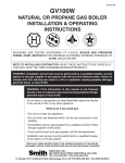
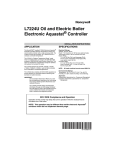
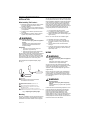
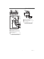
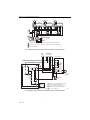
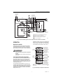
L8124A,C,E,L and M
Aquastat® Relays
INSTALLATION INSTRUCTIONS
APPLICATION
SPECIFICATIONS
These immersion type controllers are used with forced
hydronic heating systems that include domestic hot water
service. All models provide high limit, low limit and
circulator control. Table 1 lists the various models and
their applications.
Low Limit:
Setting: 110°F to 220°F (43°C to 104°C), adjustable.
Differential: 10°F to 25°F (6°C to 14°C), adjustable.
These Aquastat® relays have a diaphragm powerhead
and MicroSwitch™ assembly that respond to
temperature changes in the boiler water. L8124 can
provide multizone control by using a separate circulator
and R845 Relay for each zone. L8124E and L have large
transformers and extra terminals for supplying power to
low voltage valves. L8124L includes a large transformer
and extra terminals for low voltage zone valves. L8124M
is for use in a wood-coal/gas-oil multifuel heating system.
Circulator is independently controlled by the thermostat.
High Limit:
Setting: 130°F to 240°F (54°C to 116°C), adjustable.
Differential: 10°F (6°C), fixed.
WARNING
Explosion Hazard.
Can cause serious injury, death or property
damage.
Use this product only in systems with a pressure
relief valve.
Do not use these Aquastat® Relays where the pressure
can exceed 100 psi (690 kPa) on the bulb if inserted
directly or 200 psi (1380 kPa) when using an immersion
well, or where the ambient temperature can exceed
150°F (66°C) at the case or 265°F (129°C) at the sensing
element.
Table 1. Model Descriptions.
Model
Number
L8124A
Burner
Control
Circuit
120V
No. of V8043 Zone
Valves Powered
Without Additional
Transformer
Can Be Used For
Multizone With
Circulatorsa
Yes
—
L8124C
L8124L
Electrical Ratings
Burner Circuit
Same as L8124A,C,L
circulator rating.
3
L8124E
24V
2
1.25A at 24 Vac; 30 VA
(total load) B1-B2, Tv-Z.
L8124M
120V
—
Same as L8124A.
a
Circulator Circuit
120 Vac: 7.4A (full load),
44.4A (locked rotor).
240 Vac: 3.7A (full load),
22.2A (locked rotor).
None.
Multizone control can be provided by using a separate circulator and R845 Relay for each zone.
® U.S. Registered Trademark
Copyright © 2001 Honeywell • All Rights Reserved
95-6571-11
L8124A,C,E,L AND M AQUASTAT® RELAYS
INSTALLATION
with the relay.) Refer to form 68-0040, Wells and Fittings
for Temperature Controllers, to order well. A compression
fitting is available for applications where direct immersion
of the sensing bulb is desired. A 124904 Well Adapter
(see Fig. 2) can be ordered separately to adapt some
other wells to the mounting clamp. The boiler must be
provided with a tapping that allows horizontal mounting of
the well. It should be located where boiler water of
average temperature can circulate around the well.
When Installing This Product…
1.
2.
3.
4.
Read these instructions carefully. Failure to follow
them could damage the product or cause a
hazardous condition.
Check the ratings given in the instructions and on
the product to make sure the product is suitable for
your application.
Installer must be a trained, experienced service
technician.
After installation is complete, check out product
operation as provided in these instructions.
1.
2.
3.
NOTE: Do not use the case as a handle to tighten.
WARNING
4.
5.
Electrical Shock Hazard.
Can cause severe injury, death or equipment
damage.
Disconnect power supply before beginning
installation to prevent electrical shock or
equipment damage.
6.
7.
IMPORTANT
1. Terminals on these Aquastat Relays are
approved for copper wire only.
2. Immersion well must fit sensing element and
bulb must rest against bottom of well.
Bend the tubing, if necessary, to hold the bulb against the
bottom of the well. Do not make a sharp bend in the
tubing. A sharp bend can produce a break in the tubing
and cause loss of fill. This condition will cause the high
and low limit controllers to be continuously made.
WARNING
Electrical Shock Hazard.
Can cause severe injury, death or equipment
damage.
Disconnect power before wiring to prevent
electrical shock or equipment damage.
All wiring must comply with local electrical codes and
ordinances. The limits given in the Specifications section
must not be exceeded when applying this control.
Terminals on these Aquastat Relays are approved for
copper wire only.
3
Refer to the insert on the inside of the Aquastat Relay
cover or to Table 1 for electrical ratings and maximum
load information. Use manufacturer instructions when
wiring controlled equipment or refer to typical hookups in
Fig. 3 through 11.
2
CAUTION:
EXCESSIVE HANDLING OR SHARP BENDS
CAN DAMAGE THE CAPILLARY.
1
SENSING ELEMENT IS FACTORY FORMED FOR 1.5 IN.
INSULATION WELL ASSEMBLIES.
2
FOR 3 IN. INSULATION WELL ASSEMBLIES, PULL OUT
SUFFICIENT CAPILLARY TO ASSURE THAT THE CAPSULE
BOTTOMS IN THE WELL.
3
STRAIGHTEN CAPILLARY SUFFICIENTLY SO IT DOES NOT
INTERFERE WITH INSERTION OF THE CAPSULE INTO THE WELL. M8882
WARNING
Explosion Hazard.
Can cause severe injury, death or property
damage.
Use this product only in systems with a pressure
relief valve.
If the B1 terminal on the device being replaced is a 1/4 in.
(6 mm) tab terminal, use the existing wiring harness
terminals to install the replacement device. If the B1
terminal on the device being replaced is a screw
terminal, insert the provided tab terminal to screw
terminal adapter on the 1/4 in. (6 mm) tab terminal of the
replacement device. After the adapter is installed, the
existing wraparound wire end may be reused to make an
electrical connection to the B1 terminal.
Fig. 1. Adjusting the capillary length.
Mounting
Each relay is suitable for use with an immersion well for
insertion into the boiler. (Check individual OS number
specifications to determine whether a well is supplied
95-6571—11
Refill boiler and check for water leakage.
Loosen but do not remove the clamp screw on
the bottom (L8124A,E) or on top (L8124C,L,M)
of case.
Insert the element in the well until it bottoms.
See Fig. 2.
Fit the case onto the well so that the clamp on the
case slides over the flange on the well. Securely
tighten clamp screw.
WIRING
Select models have an adjustable capillary length.
See Fig. 1.
1
Turn off all power and drain the boiler.
If no tapping is provided, prepare one, properly
sized and threaded, at the selected location.
Install the immersion well in the boiler tapping and
tighten securely.
2
L8124A,C,E,L AND M AQUASTAT® RELAYS
CONTROLLER
CASE
IMMERSION
WELL CLAMP
BACK OF
CONTROLLER
CASE
BOILER
IMMERSION
WELL CLAMP
1
IMMERSION
WELL SPUD
ADAPTER
ADAPTER
OLD IMMERSION
WELL ASSEMBLY
IMMERSION
WELL CLAMP
SCREW
SENSING
BULB
(A)
)
(B)
2
(D)
HEAT-CONDUCTIVE COMPOUND
1
CAPILLARY
TUBE
2
SETSCREW
ASSURE THAT CAPILLARY TUBE FITS FREELY IN THE ADAPTER SO THE
TENSION OF THE CAPILLARY TUBE AT POINT (C) HOLDS THE SENSING
BULB IN GOOD THERMAL CONTACT WITH THE IMMERSION WELL AT POINT (D
SHORT TUBE
FITS IN CENTRAL
RECESS OF ADAPTER
IMMERSION
WELL CLAMP SCREW
BEND THE CAPILLARY TUBE TO HOLD THE SENSING BULB IN GOOD
THERMAL CONTACT WITH THE IMMERSION WELL AT POINTS (A) AND (B).
M883
Fig. 2. Position of bulb in immersion well and use of well adapter when required.
LOW VOLTAGE
THERMOSTAT
LOW VOLTAGE
THERMOSTAT
L8124E
L8124A,C
2
2
G
G
T
TV
T
T
1
L1
(HOT)
2
L2
1K
Z
1K
1
1
L1
(HOT)
2
L2
1
1K2
R
W
B
LOW LIMIT/
CIRCULATOR
W
1K1
ZR
B
1K2
R
B
1K1
R
ZC
HIGH
LIMIT
R
LOW LIMIT/
CIRCULATOR
3
HIGH
LIMIT
LINE VOLTAGE
OIL BURNER
RELAY OR
GAS VALVE
C1
LINE VOLTAGE
CIRCULATOR
B
C2
3
B1
TR
B1
B2
B2
C1
TH
LOW VOLTAGE
GAS VALVE
(eg, VR8300)
C2
LINE VOLTAGE
CIRCULATOR
1
POWER SUPPLY. PROVIDE DISCONNECT MEANS AND
OVERLOAD PROTECTION AS REQUIRED.
2
CONTROL CASE MUST BE CONNECTED TO EARTH GROUND.
USE GROUNDING SCREW PROVIDED.
3
B1 IS 1/4 IN. TAB TERMINAL.
1
POWER SUPPLY. PROVIDE DISCONNECT MEANS AND
OVERLOAD PROTECTION AS REQUIRED.
2
CONTROL CASE MUST BE CONNECTED TO EARTH GROUND.
USE GROUNDING SCREW PROVIDED.
3
B1 IS 1/4 IN. TAB TERMINAL.
M8803
Fig. 4. L8124E single zone connections
and internal schematic.
M8802
Fig. 3. L8124A,C single zone connections
and internal schematic.
3
95-6571—11
L8124A,C,E,L AND M AQUASTAT® RELAYS
T87F
T87F
L8124A
T
ZR
T
T
L1 C1 C2 B2 B1
1
2
3
2
G
L2
T87F
R845 RELAY
ZC
T
3
4
5
6
R845 RELAY
T
T
1
2
3
4
6
5
L2
L1
(HOT)
1
PUMP
PUMP
PUMP
R8184
F
T
F
C554
WHITE
T
BLACK
BURNER
AND
IGNITION
ORANGE
1
POWER SUPPLY. PROVIDE DISCONNECT MEANS AND OVERLOAD PROTECTION AS REQUIRED.
2
CONTROL CASE MUST BE CONNECTED TO EARTH GROUND. USE GROUNDING SCREW PROVIDED.
3
B1 IS 1/4 IN. TAB TERMINAL.
M8822
Fig. 5. L8124A in an oil-fired, forced hot water, tankless, zoned, pump system.
LOW VOLTAGE
THERMOSTAT
2
L1
(HOT)
L2
1
TO ADDITIONAL
R845A RELAYS
FOR OTHER ZONES
L8124A,C
G
R845A RELAY ZONE 2
T
T
1
ZONE 2
CIRCULATOR
6
2
1K
5
R
W
B
LOW LIMIT/
CIRCULATOR
3
1K1
4
ZR
ZC
1
LINE VOLTAGE
OIL BURNER
RELAY OR
GAS VALVE
B
HIGH
LIMIT
1K2
R
3
2
ZONE 2
LOW VOLTAGE
THERMOSTAT
B1
B2
1
POWER SUPPLY. PROVIDE DISCONNECT MEANS AND
OVERLOAD PROTECTION AS REQUIRED.
2
CONTROL CASE MUST BE CONNECTED TO EARTH
GROUND. USE GROUNDING SCREW PROVIDED.
3
B1 IS 1/4 IN. TAB TERMINAL.
C1
C2
LINE VOLTAGE
CIRCULATOR
M8827
Fig. 6. L8124A,C multizone system with circulator connections and internal schematic.
95-6571—11
4
L8124A,C,E,L AND M AQUASTAT® RELAYS
ZONE 1
THERMOSTAT
1
L1
(HOT)
ZONE 2
THERMOSTAT
V8043F
V8043F
T87F
L2
2
TH
TR
TH
TH
TR
TR
G
TR
TH
L2
L1
T
T
L8124E
3
2
C1
C2
B2
B1
L8124G,L
3
G
TV
T
Z
TH
L1
(HOT)
1
1K
CIRCULATOR
L2 1
2
1K1
R
W
B
ZC
1K2
B
HIGH
LIMIT
4
R
1
POWER SUPPLY. PROVIDE DISCONNECT MEANS AND
OVERLOAD PROTECTION AS REQUIRED.
2
CONTROL CASE MUST BE CONNECTED TO EARTH GROUND.
USE GROUNDING SCREW PROVIDED.
3
B1 IS 1/4 IN. TAB TERMINAL.
ZR
LOW LIMIT/
CIRCULATOR
LINE VOLTAGE
OIL BURNER
RELAY OR
GAS VALVE
TR
LOW VOLTAGE
GAS VALVE
(eg, VR8300)
M1796A
Fig. 8. L8124E in a 24Vac, gas-fired,
forced hot water, tankless system.
B1
B2
C2
C1
LINE VOLTAGE
CIRCULATOR
1
POWER SUPPLY. PROVIDE DISCONNECT MEANS AND
OVERLOAD PROTECTION AS REQUIRED.
2
UP TO TWO V8043F ZONE VALVES CAN BE POWERED WITH
L8124G,L. ADD ADDITIONAL TRANSFORMER FOR EVERY
TWO OR LESS VALVES.
3
CONTROL CASE MUST BE CONNECTED TO EARTH GROUND.
USE GROUNDING SCREW PROVIDED.
4
B1 IS 1/4 IN. TAB TERMINAL.
M1795B
Fig. 7. L8124 multizone system with zone valve
connections and internal schematic.
5
95-6571—11
L8124A,C,E,L AND M AQUASTAT® RELAYS
T87F
T87F
R845 RELAY
T
T
1
2
3
4
5
T87F
R845 RELAY
6
T
T
1
2
3
4
5
6
R845 RELAY
T
T
1
2
3
4
5
6
1
L1
(HOT)
PUMP
L2
PUMP
PUMP
2
G
L2
L1
T
T
C1
C2
B2
B1
TH
3
TR
LOW VOLTAGE
GAS VALVE
(eg, VR8300)
L8124E
AQUASTAT® RELAY
1
POWER SUPPLY. PROVIDE DISCONNECT MEANS AND OVERLOAD PROTECTION AS REQUIRED.
2
CONTROL CASE MUST BE CONNECTED TO EARTH GROUND. USE GROUNDING SCREW PROVIDED.
3
B1 IS 1/4 IN. TAB TERMINAL.
M1794A
Fig. 9. L8124E in a 24 Vac, gas-fired, forced hot water, tankless, zoned pump system.
1
TO ADDITIONAL
R845A RELAYS
FOR OTHER ZONES
L2 L1
(HOT)
R845A RELAY ZONE 1
6
5
L8124E
2
3
G
T
TV
Z
4
1
1K
1
2
2
1K2
W
R
B
ZONE 1
LOW VOLTAGE
THERMOSTAT
1K1
LOW LIMIT/
CIRCULATOR
R
HIGH
LIMIT
ZONE 1
CIRCULATOR
C1
B
C2
3
B1
TR
B2
THTR
TH
LOW VOLTAGE
GAS VALVE (eg, VR8300)
1
POWER SUPPLY. PROVIDE DISCONNECT MEANS AND
OVERLOAD PROTECTION AS REQUIRED.
2
CONTROL CASE MUST BE CONNECTED TO EARTH
GROUND. USE GROUNDING SCREW PROVIDED.
3
B1 IS 1/4 IN. TAB TERMINAL.
Fig. 10. L8124E multizone system with circulator connections and internal schematic.
95-6571—11
6
M8828
L8124A,C,E,L AND M AQUASTAT® RELAYS
LOW VOLTAGE
THERMOSTAT
ZONE 1
1
L2
L1
(HOT)
TO ADDITIONAL
R845A RELAYS
FOR OTHER ZONES
L8124L
2
G
TV
T
Z
R845A RELAY ZONE 2
1
1K
ZONE 2
CIRCULATOR
6
2
5
1K1
R
W
B
ZR
3
LOW LIMIT/
CIRCULATOR
4
ZC
1K2
B
HIGH
LIMIT
1
3
R
2
B1
LINE VOLTAGE
OIL BURNER
RELAY OR
GAS VALVE
B2
C2
ZONE 2
LOW VOLTAGE
THERMOSTAT
C1
LINE VOLTAGE
CIRCULATOR
ZONE 1
1
POWER SUPPLY. PROVIDE DISCONNECT MEANS AND
OVERLOAD PROTECTION AS REQUIRED.
2
CONTROL CASE MUST BE CONNECTED TO EARTH
GROUND. USE GROUNDING SCREW PROVIDED.
3
B1 IS 1/4 IN. TAB TERMINAL.
M8829
Fig. 11. L8124L multizone system with circulator connections and internal schematic.
OPERATION
EXAMPLE: Setpoint of 140°F (60°C), differential set
at 25°F (14°C). On a temperature rise, R-B breaks
and R-W makes at 155°F (68°C). On a temperature
fall, R-B makes and R-W breaks at 130°F (54°C).
High Limit Controller
The high limit opens and turns off the burner when the
water temperature reaches the setpoint. The high limit
automatically resets after the water temperature drops
past the setpoint and through the 10°F (6°C) differential.
HIGH LIMIT
SETTING
WARNING
SWITCH BREAKS ON
TEMPERATURE RISE.
BURNER TURNS OFF.
CIRCULATOR OPERATES
ON A CALL FOR HEAT.
SWITCH MAKES ON
TEMPERATURE FALL.
BURNER OPERATES ON A
CALL FOR HEAT.
Explosion Hazard.
Can cause serious injury, death or equipment
damage.
Use this product only in systems with a pressure
relief valve.
LOW LIMIT
AND
CIRCULATOR
SETTING
Low Limit and Circulator Controllers
On a temperature rise, with the adjustable differential at
the minimum setting of 10°F (6°C), the burner circuit
(R-B) breaks and the circulator circuit (R-W) makes at
the control setpoint. On a temperature drop of 10°F (6°C)
below the setpoint, the R-B circuit makes and the R-W
circuit breaks. See Fig. 12.
SWITCH MAKES R-W
AND BREAKS R-B ON
TEMPERATURE RISE.
1
SWITCH MAKES R-W
AND BREAKS R-B ON
TEMPERATURE RISE.
SWITCH MAKES R-B AND
BREAKS R-W ON
TEMPERATURE FALL.
BURNER IS ON TO
MAINTAIN MINIMUM
WATER TEMPERATURE.
CIRCULATOR IS OFF.
At any differential setting greater than 10°F (6°C), the
R-B make temperature and the R-W break temperature
remain the same (control setting minus 10°F [6°C]). The
R-B break and R-W make temperature are the setpoint
temperature plus the difference between the differential
setting and 10°F (6°C).
1
WHEN WATER REACHES PROPER TEMPERATURE, THE BURNER
SHUTS OFF OR THE CIRCULATOR PUMP STARTS (WHEN CALLING
FOR HEAT).
M1523
Fig. 12. Relationship of setpoints and differential.
7
95-6571—11
L8124A,C,E,L AND M AQUASTAT® RELAYS
On the L8124M, the burner and circulator circuits are
separately controlled; the low limit controls the burner
circuit (R-B) as described above, while the low voltage
thermostat directly controls the circulator circuit.
See Fig. 13.
LOW VOLTAGE
THERMOSTAT
G
T
1K1
R
CHECKOUT
L1
L1
(HOT)
L2
L2
1K
W
Follow the boiler manufacturer recommendations when
making the L8124 settings. The high limit setting must be
at least 20°F (11°C) higher than the low limit setting. Set
the indicators over the selected temperature marks. The
low limit differential is set by turning the differential
adjustment knob to the desired amount of differential.
The thermostat heat anticipator should be set at 2.0A.
2
L8124M
T
SETTING
1
Put the system into operation and observe each function
through at least one complete cycle. Be sure the control
operates as intended.
ZC
LINE VOLTAGE
CIRCULATOR
B
C1
LOW LIMIT
C2
B
HIGH
LIMIT
R
3
LINE VOLTAGE
OIL BURNER
RELAY OR
GAS VALVE
B1
B2
1
POWER SUPPLY. PROVIDE DISCONNECT MEANS
AND OVERLOAD PROTECTION AS REQUIRED.
2
CONTROL CASE MUST BE CONNECTED TO EARTH
GROUND. USE GROUNDING SCREW PROVIDED.
3
B1 IS 1/4 IN. TAB TERMINAL.
M8804
Fig. 13. L8124M single zone connections
and internal schematic.
Automation and Control SolutionsAutomation and Control Solutions
Honeywell
1985 Douglas Drive North
Golden Valley, MN 55422
95-6571—11
G.R. Rev. 12-01
Honeywell Limited-Honeywell Limitée
35 Dynamic Drive
Scarborough, Ontario
M1V 4Z9
www.honeywell.com


![取扱説明書〈詳細版〉 [F-04B]](http://vs1.manualzilla.com/store/data/006532339_2-7161c531ccad3db4d0b2b0530d68e7ed-150x150.png)