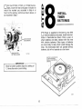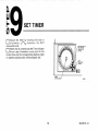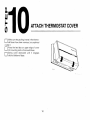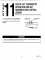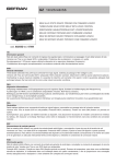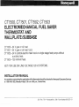
1
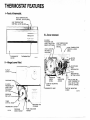
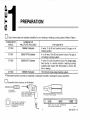
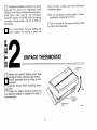
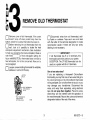
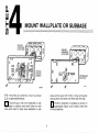
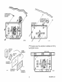
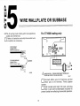
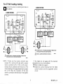
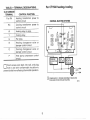
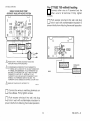
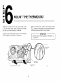
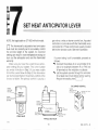
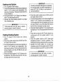
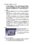
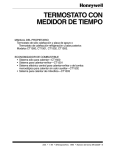
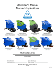
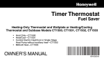
CTl500, CT1501, CT1502, CT1503
ELECTROMECHANICAL FUEL SAVER
THERMOSTAT AND
WALLPLATEEUBBASE
CTI500-24 V gas or oil heat.
CTl501-24 V gas or oil heat/cool.
CTI502--24 V central electric heat/cool or single stage heat pump without
auxiliary heat.
CTI 503-750 millivolt heat.
NOT FOR USE ON LINE VOLTAGE (120 V) SYSTEMS.
INSTALLATION MANUAL
Any questions concerning the applicationof this thermostat should be directed to HoneywellConsumer Services
at 1-800-468-1502, Monday-Friday 7 3 0 a.m.-500 pm., Central time.
S.M. Rev. 7-91 aHoneywell Inc. 1991 Form Number 69-0273-9
THERMOSTAT FEATURES
I-Front
of thermostat.
H l G H TEMPERATURE
CONTROL L E V E R (RED)
LOW TEMPERATURE
CONTROL LEVER (BLUE)-
1
Ill-Cover
removed.
24 HOUR
PROGRAM DIAL
'THERMOSTAT
COVER
Il-Hinged
THERMOMETER
1
11.711
cover lifted.
.. .~
.
,
.
.
.
.
.
.
ANTICIPATOR
PROGRAM PINS A
"--CAPTIVE M O U N T I N G
HIND THERMOSTAT.
H E L D O N BY TWO
CAPTIVE SCREWS.)
"1
k
PREPARATION
((1
THERMOSTAT
MODEL
SUBBASE OR
WALLPLATE INCLUDED
CT1500
199986C Wallplate
2-wire, 15 to 30 volt control circuit For gas or oil
heating system.
CT1501
Q682A1079 Subbase
4- or 5-wire, 15 to 30 volt control circuit For gas or
oil heating/cooling system.
CT1502
Q682B1227 Subbase
4-wire, 15 to 30 volt control circuit. For single stage
heat pump or central electric heatinglcooling
systems that require the thermostat to control the
fan in heatino.
CT1503
199986D Wailp ate
FOR USE WITH
[
750 mill volt single-stage heating system.
aThermostat must be mounted on wallplate or subbase included in package to assure operation.
0
Assemble tools required, as illustrated
0
MASKING TAPE. IF NEEDED TO
LABELWIRESASTHEYARE
OISCONNECTED FROM OLD
THERMOSTAT
does not work, contact your local heatingfair
conditioning dealer.
If wallplate or subbase is mounted on a vertical
outlet box (check old installation), order
196393A Cover Plate and Adapter Ring (see appropriate figure under step 4). Call Honeywell
Consumer Services (1-800-468-1502) for ordering
information, Monday-Friday, 7:30 a.m. to 500 p.m.
Central time.
NOTE: Do not operate cooling system if outdoor
temperature is below 50' F [looC].
Turn off power to the heatingfcooling System
at the main fuse panel.
Test to make certain that your heating and
cooling systems are working. If either one
i2
F
UNPACK THERMOSTAT
0
THERMOIIAT
Remove and discard shipping wrap. Save
package of screws, instructions and receipt
Remove thermostat cover by lifting up from
the bottom.
Carefully remove insert protecting switch
bulbs.
Loosen two captive mounting screws, and
separate wallplate or subbase from back of
thermostat base.
0
.
0
0
IFT
OVER
SCREWS
12.612
2
.
“3
F
REMOVE OLD THERMOSTAT
0
Remove cover of old thermostat. If the cover
doesn’t snap off when pulled firmly from the
bottom, check for a screw that locks the cover on.
Before removing the old thermostat from the
wall, look at it carefully to locate the heat
anticipator adjustment mechanism. (See illustration
to help you recognize the heat anticipator.) Make a
note h e r e l l o f that anticipator setting for
future reference. If your thermostat does not have a
heat anticipator, do not be concerned. Move on to
next paragraph.
Loosen screws holding thermostat to wallplate,
subbase or wall and lift away.
0
0
Disconnect wires from old thermostat wallplate or subbase. Tape each wire and label
with the letter of the terminal designation to make
reconnection easier. If there are only two wires,
labeling is not necessary.
IMPORTANT
thermostat cannot be used on your system.
EXCEPTION: The CT1502 thermostat can be
used on a system with B or 0 terminals.
One or two extra wires?
If you are replacing a Honeywell Chronotherm
thermostat, you may find one or two wires that go to
the clock terminals on the Chronotherm thermostat
wiring wallplate. Do not allow them to touch, or you
may damage your transformer. Disconnect the
wires, and wrap them separately, using electrical
tape. Do not wrap them together. Place the wires
where they will not interfere with the operation of
the new thermostat. Record the colors and terminal
designation labels of the rest of the wires.
3
69-0273-9
~
“4
b
10
MOUNT WALLPLATE OR SUBBASE
If mounting on outlet box, mount as shown
on appropriate figure.
base will be level. Drill 3/16 in. holes and gently
tap anchors into holes until flush with the wall.
If mounting
wall, hold wallplate or sub. ’ on
..
base in position and mark holes on wall.
Use spirit level to make sure wallplate or sub-
Position wallplate or subbase as shown in
appropriate figure, and loosely insert the
screws supplied.
4
nCarefully level the wallplate or subbase and firmly
u tighten screws.
..
SPIRIT LEVEL
‘‘wm
WALLPLATE
SCREWS
“2)
5
69-0273-9
WIRE WALLPLATE OR SUBBASE
-
For CT1500 heating-only
MOTE: All wiring must comply with local electrical
codes and ordinances.
Refer to illustration and strip thermostat wire
insulation as necessary.
0.:
.F"rn
-. .~STFldilRUT
- . . .. . .
CONNECTION-
FOR WRAPAROUND
CONNECTIONSTRlP7116In. [11 mml
0
,
I
I
BARRIER
A
POWER SUPPLY. PROVIDE DISCONNECT MEANS AND
OVERLOAD PROTECTIONAS REOUIRED.
Wlll
Connect either wire to R terminal and the
other wire to W terminal. Firmly tighten
screws.
Push excess wire back into wall, and plug
hole In wall with nonflammable Insulation to
prevent drafts from affecting thermostat operation.
0
6
For CT1501 heating/cooling
Connect the wires to matching terminals on
the subbase.
4-WIRE SYSTEM
U
U
5-WIRE SYSTEM
I
I
I
I
RELAY OR
VALVE COIL
I
1
I
I
CONTACTOR
I
A
POWER SUPPLY. PROVIDE DISCONNECT MEANSAND
A
INSTALL JUMPER BETWEEN RC AND RH.
OVERLOAD PROTECTIONAS REOUIRED.
Ma"
POWER SUPPLY. PROVIDE DISCONNECT MEANS AND
M2&13
NOTE: If there are four wires, connect wire
marked R to terminal R H and add a jumper
wire to connect to RC. If RC is left unconnected, the air conditioner will not turn on. The
4-wire drawing on this page shows how to jumper
RC to RH. Strip the insulation off the wire
where if connects to the terminals. Firmly tighten
screws.
If the labels do not agree with the terminal
designations on your new subbase
Refer to Table 2 on page 8
Determine correct hookup from the listed
control function and the equipment control
circuit
69-0273-9
7
~
~
For CT1502 heatinglcooling
OLDSUBBASE
TERMINAL
CONTROL FUNCTION
R or RH
Heating transformer power to
control circuit
RC
Heating relay or valve.
Y
Cooling relay.
G
Fan relay.
Heating changeover valve or
damper control circuit.
Cooling changeover valve or
damper control circuit.
Heat pump compressor control
0
P
I
I I
Cooling transformer power to
control circuit.
W
B
CENTRAL ELECTRIC SYSTEM
I 1
U
CONTACTOR
RELAY OR
VALVE COIL
Push excess wire back into wall. and plug
hole in wall with nonflammable insulation to
prevent drafts from affecting thermostat operation.
A
8
POWER SUPPLY. PROVIDE DISCONNECT MEANSAND
OVERLOAD PROTECTION AS REOUIRED.
M%1*
CT1502, continued
For CT1503 750-millivolt heating
Connect either wire to R terminal and the
other wire to W terminal. Firmly tighten
screws.
SINGLE STAGE HEAT PUMP
(WITHOUT AUXILIARY HEAT) SYSTEM
I -
-
1
Push excess wire back into wall, and plug
hole in wall with nonflammable insulation to
prevent drafts from affecting thermostat operation.
0
0
0
/
1
+
L'
(HOT)
u+
A
A
A
POWER SUPPLY PROVIDE DISCONNECT MEANS AND
OVERLOPD PROTECTION AS REQUIRED
CQZOOA OR
0313A
IFCOMPRESSOR ISCONNECTEDTO OLDTHERMOSTATS
"YTERMINALWITH A JUMPERTO"W, USE NEW THERMOSTATS
"PTERMINAL FORCOMPRESSOR. IFOLOTHERMOSTATHAS
ONE WIRETO"Y"AND0NE TO " W . U S t ' Y AND " W ' O N NEW
THERMOSTAT, DO NOT U S E " P . IMPORTaNT- IF OLD
THERMOSTAT USES A W2 (AUXILIARY OR EMERGENCY HEAT)
TERMINAL, THIS THERMOSTAT MAY NOT BE USED THIS
THERMOSTAT IS NOT DESIGNED TO CONTROL AUXILIARY HEAT
SOMEHEATPUMPSUSE"B"INSTEAD0F"O'
M24IB
THERMOPILE
M211511
Connect the wires to matching terminals on
the subbase. Firmly tighten screws.
0
0
Push excess wire back into wall, and plug
hole in wall with nonflammable insulation to
prevent drafts from affecting thermostat operation.
9
69-0273-9
L
MOUNT THE THERMOSTAT
or subbase as shown in illustration.
Do NOT cycle heating system until Step 7 is
completed.
10
SET HEAT ANTICIPATOR LEVER
-
NOTE: Not applicable on CT1503 millivolt model.
The thermostat's adjustable heat anticipator
must be correctly set to accurately control
the on-time length of the system. An incorrect
setting can result in room temperature swings or
burn out the anticipator and void the thermostat
warranty.
Make sure you have the current draw (anticipator setting) for your system. This i s the number
you wrote in the box in Step 3 If you were unable
to find the current draw for Step 3, this information
can be found printed on the primary control at the
furnace or boiler. The primary control is usually a
0
gas valve a relay or burner controi box, Aquastat
controller or zone valve with the thermostat wires
connected to it These controls are usually located
behind the furnace cover See next illustration
If current rating is still unavailable, proceed as
follows:
Coqnect the probes of an ac ammeter (0 to
2.0 A,for example) between R (or RH) and
W terminals on the wallplate or subbase.
Let the system operate through the ammeter
for at least one minute before taklng reading.
Record the reading here
“8
On the CT1500. CT1501 or CT1502 thermostats, move the heat anticipator indicator to
match the number you recorded in Step 4 or
found on the primary control as shown above, or
as recorded in Step 7
F
0
INSTALL
TIMER
BATTERIES
teries in thermostat as shown. Once a year, or
when batteries are dead, replace with two new
AAA alkaline batteries. Other types of batteries
are more likely to leak, which could damage the
timer. The thermostat itself will operate without
batteries, but will not operate as a fuel saver.
\ANTICIPATOR
SETTING LEVER
11,7164\
12
SET TIMER
Adjust the timer by moving the knob in
clockwise
d i r e c t i o n . Do NOT
reverse the knob.
When time is correctly set, the Time Indicator
Arrow (see illustration) must point to the
correct time and the corresponding daytime (lighr)
or nighitime (dark) portion of the program dial.
0
13
69-0273-9
“10
I-
0
ATTACH THERMOSTAT COVER
Make sure the packing inserts in the thermostat base have been removed. as explained
in step 3
Place the two tabs on upper edge of cover
into mounting slots i n thermostat base
Swing cover downward until it engages
catch at bottom of base
0
0
0
. .
14
il1
b
cn
CHECK OUT THERMOSTAT
OPERATION AND SET
TEMPERATURE CONTROL
LEVERS
The two levers on top of the thermostat
control the low and high temperature for
energy savings and comfort control, as shown in
illustration.
LOW TEMP.lBL"E MARK1
SET LEVER
1
Do NOT check operation by shorting across terminals of relay or valve coil; this will burn out the
thermostat heat anticipator, which will void the warranty.
15
~
69-0273-9
I
Heating-only System
0 Turn on power to the furnace.
0 Push both temperaturecontrol leverstogetherat
least 5" F [3" C] above room temperature. The
heat should comeon.Thefan will startwhen the
furnace heats up.
0 Move both levers5" F [3"C] below room temperature. The heat should shut off.
0 Operate the entire heating system for at least
one complete cycle.
IMPORTANT
If thermostat fails any test, refer to troubleshooting guide in owner's manual.
Heating/Cooling System
0 Turn on power to the furnace and cooling
system.
0 Place the system switch lever at HEAT and the
fan switch lever at AUTO.
0 Push both temperaturecontrol leverstogetherat
least 5'F [3"C] above room temperature. The
heat should comeon.Thefan will startwhen the
furnace heats up. On the CT1502, the fan will
start immediately.
0 Moveboth leverstogether5"F[3"C]belowroom
temperature. The heat should shut off. The fan
will stop when the furnace cools.
IMPORTANT
the cooling system if outdoor temperature is
below 50°F [lO°C]. Refer to manufacturer's
recommendations.
0 Place the system switch lever at COOL and the
fan switch lever at AUTO.
0 Push both temperature control levers together at
least 5 O F [3" C] below room temperature. The
cooling equipment should operate, and the fan
will start. Allow for any time delay that may be
built into the compressor control circuit.
0 Movebothleverstogether5°F[30C]aboveroom
temperature. The cooling equipment should shut
off.
0 Place the fan switch at ON. The fan should run
continuously with the system switch in any
position.
0 Place the system switch at OFF. Move both
temperature: levers to various positions. The
heating andcooling systems should not operate.
0 Operate the entire system for at least one
complete cycle with the system switch at COOL
and one complete cycle with the switch at HEAT.
IMPORTANT
If thermostat fails any test, refer to troubleshooting guide in owner's manual.
0 After checkout, reset both temperature levers to
desired temperatures.
0 Setthebluelevertothetemperature you wantfor
normal comfort periods.
For heating season:
REFER TO THE OWNERS MANUAL FORM 690333FOR OPERATING AND PROGRAMMING
INSTRUCTIONS.
Move the blue lever to the energy savings
temperature you want when you are sleeping or
your home is not occupied.
0 Setthered levertothetemperature you want for
normal comfort periods.
[?
IF YOU HAVE OUESTIONS REGARDING THE
INSTALLATION OF THE HONEYWELL FUEL
SAVER THERMOSTAT, PLEASE CALL OUR TOLLFREE CONSUMER SERVICES GROUP NUMBER
AT 1-800-468-1502, MONDAY-FRIDAY, 7:30 AM 5:OO PM CENTRALTIME.
For cooling season:
0 Move the red lever to the energy savings
temperature you want when you are sleeping or
your home is not occupied.
17
69-0273-9
Honeywell
Residential and
Building Controls Division
Honeywell Inc.
1985 Douglas Drive No.
Golden Valley, MN 55422
Residential and
Building Controls Division
Honeywell Limited-Honeywell
740 Ellesmere Road
Scarborough, Ontario
M1P 2VY
Helping You Conlrol Your World
Lunltke