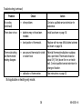
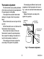
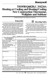
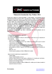
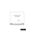
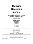
1
Timer Thermostat
Fuel Saver
Heating-Only Thermostat and Wallplate or Heating/Cooling
Thermostat and Subbase Models CT1500, CT1501, CT1502, CT1503
• Heat Only—CT1500
• Heat/Cool—CT1501
• Central Electric Heat/Cool or Single Stage
Heat Pump without auxiliary heat—CT1502
• Millivolt Heat—CT1503
OWNER’S MANUAL
69-0333-6
Welcome to the world of energy savings with your new Honeywell Fuel Saver Thermostat. The
Honeywell name is your assurance of accurate control and reliable operation for years to come.
Your new thermostat will automatically control the temperature in your home to provide a high
level of comfort plus energy savings when programmed according to the instructions in this
manual.
Recycling Notice
This control contains mercury in a sealed tube. Do not place control in the trash at the end of
its useful life.
If this control is replacing a control that contains mercury in a sealed tube, do not place your
old control in the trash.
Contact your local waste management authority for instructions regarding recycling and the
proper disposal of the control, or of an old control containing mercury in a sealed tube.
2
69-0333—6
Table of Contents
PAGE
Features of Your Thermostat .............................................................................................. 4
Reviewing Your Family Schedule ....................................................................................... 7
Setting The Temperature .................................................................................................... 8
Setting Subbase Switches .................................................................................................. 9
Inserting Timer Batteries ................................................................................................... 10
Setting The Timer .............................................................................................................. 11
Programming ..................................................................................................................... 12
Temporarily changing the program .............................................................................. 15
Troubleshooting ................................................................................................................ 17
Servicing The Thermostat ................................................................................................. 21
System on-time adjustment .......................................................................................... 21
Thermometer adjustment ............................................................................................. 22
Limited One-Year Warranty .............................................................................................. 27
3
69-0333—6
Features of Your Thermostat
1
1 FLIP-UP COVER. Lift up cover to set timer
for energy savings and normal temperature periods .
2 THERMOSTAT COVER. Lift up cover and
remove to adjust heat anticipator or install
batteries.
3 THERMOMETER. Provides accurate room
temperature reading.
4 TIMER. Provides 24-hour slotted dial to
hold the programming pins.
5 TIMER SETTING KNOB. Turn clockwise
to match the correct a.m. or p.m. time to
the time indicator.
6 TIME INDICATOR. Arrowhead indicates
time for 24-hour dial.
7 PROGRAM INDEX WHEEL. Controls high
and low temperature at specific time of
day as set by program pins. Can be
moved to temporarily override a schedule.
2
3
M8750
4
69-0333—6
8
8 TEMPERATURE SETTING LEVERS.
Left (blue mark) controls the low temperature; right (red mark) controls the high
temperature.
9 PROGRAM PINS. Must be inserted into
24-hour timer dial slots to control program
index wheel.
10 PIN SLOTS. Located on 24-hour dial at
ten minute intervals for program pin
insertion.
11 HEAT ANTICIPATOR SCALE PLATE.
Calibrated to match the heating system
current draw in amperes.
12 ANTICIPATOR SETTING LEVER. Must be
adjusted to match the heating system
primary control current.
13 BULB AND BIMETAL ELEMENT (2).
Provides automatic temperature control by
switching the heating or cooling system on
and off.
5
14
4
13
9
10
7
6
11
12
M8749
14 AAA ALKALINE BATTERIES (2). Included
to provide power to the timer.
5
69-0333—6
15 WALLPLATE Provides mounting base and
wiring connections for heating-only
thermostat.
16 SUBBASE Provides mounting base, wiring
connections and manual switching control
for heating/cooling thermostat.
15
M2421
O
B
R
W
G
Y
16
FAN
ON
AUTO
HEAT
OFF
COOL
M2411
6
69-0333—6
Reviewing Your Family Schedule
Write the answers to the following questions in the spaces provided to determine the program
that fits your family schedule.
What comfort temperature would you like to maintain?
What energy savings temperature would you like to maintain?
What time does the first person get up in the morning?
Is anyone home all day?
What times does the last person leave in the morning?
What times does the first person return home in the evening?
What time does the last person go to bed?
7
SUMMER
___________
___________
___________
___________
___________
___________
___________
WINTER
__________
__________
__________
__________
__________
__________
__________
69-0333—6
Setting The Temperature
For Heating:
Set the left lever (blue mark) to the energy
savings temperature you want when you are
sleeping or your home is unoccupied. See Fig. 1.
Set the right lever (red mark) to the temperature you want for normal comfort periods.
HIGH
TEMPERATURE
SETTING
LEVER
(RED MARK)
LOW TEMPERATURE
SETTING LEVER
(BLUE MARK)
50
NOTE: You may bypass the time program by
setting both the red and blue levers to the
same temperature setpoint.
60
70
80
50 60 70 80
For Cooling (Not Applicable on
Heating-only Model):
M8751
Set the left lever (blue mark)to the temperature you want for normal comfort periods.
Set the right lever (red mark) to the energy
savings temperature you want when you are
sleeping or your home is unoccupied.
Fig. 1—Setting high and low temperature
setting levers.
8
69-0333—6
The subbase fan switch controls fan
operation as follows:
ON—Fan operates continuously.
AUTO—Fan operates with cooling equipment as controlled by the thermostat or
with the heating equipment as controlled
by the plenium fan switch. In electric
heat, heat pump, and fan coil systems,
the fan is controlled by the thermostat in
heating and cooling.
Setting Subbase Switches
(If Applicable)
The subbase system switch controls system
operation as follows:
HEAT—Heating system is controlled by the
thermostat. Cooling system is off.
COOL—Cooling system is controlled by the
thermostat. Heating system is off.
OFF—Both the heating and cooling systems
are off. If the fan switch is in the AUTO
position, the fan is also off.
ON—In a cooling only application, only
cooling operates. In a heating only
application, only heating operates.
To switch positions, use thumb or index
finger to slide lever to desired position. Stop
switch lever in detent over the desired function
indicator mark for proper circuit operation.
9
69-0333—6
BATTERY LOCATION FOR
(2) AAA BATTERIES;
INSTALL WITH POSITIVE
ENDS UP
Inserting Timer Batteries
Power is supplied to the timer by two AAA
alkaline batteries (included.) Install batteries in
thermostat as shown. See Fig. 2. One a year,
or when batteries are dead, replace with two
new AAA alkaline batteries. We recommend
Energizer® batteries. The thermostat itself will
operate without batteries, but will not operate
as a fuel saver.
M8585
Fig. 2—Inserting timer batteries.
10
69-0333—6
Setting The Timer
Lift thermostat flip-up cover to find the 24-hour
program dial, slotted in ten-minute increments.
Adjust the timer to the current time by carefully
turning the knob clockwise
. Do not
reverse the knob.
When time is set correctly, the time indicator
arrow (see Fig. 3) will point to the correct time
and corresponding daytime (light) or nighttime
(dark) band of the program dial.
TIMER
SETTING
KNOB
TIME
INDICATOR
ARROW
EXAMPLE: For 11 p.m., the time indicator
arrow will point directly to the dark band on
the dial. For 11 a.m, the arrow will point to
the light band on the dial.
M1856
Fig. 3—Setting the timer.
Daylight saving time
When daylight saving time starts, carefully move the knob clockwise
one hour. When
daylight-saving time ends, carefully move the knob clockwise
23 hours. Do not reverse the
knob, or damage to the timer mechanism may occur.
11
69-0333—6
(comfort period); a blue pin is inserted at
10:00 p.m. for low temperature (energy saving
period). Two additional sets of pins are located
in the program pin storage area. You can set
up to six temperature changes with the pins
supplied. We recommend at least five hours for
each energy saving period.
To change the pins or add a new energy
saving period—
• To insert a pin, push it straight into the
selected notch on the program dial until it is
completely seated .
• To remove a pin, press against the program
dial and pull the pin straight out. Do not
attempt to change a pin if it is engaged with
the program index wheel.
• On heating/cooling systems, you must reset
the pins when the seasons change. You will
also probably want to change the lever
positions.
Programming
You can program your thermostat to
automatically lower and raise the temperature
one or more times every 24 hours.
Refer to energy savings chart on the back
cover for typical heating and cooling savings
with your new thermostat.
Before setting your program
Lift thermostat flip-up cover to find the
24-hour program dial. The slots on the program
dial (Fig. 4) are for the program pins that can
be inserted at ten-minute intervals.
Three red and three blue program pins are
included with your thermostat. The red pins
start the high-temperature period; the blue pins
start the low-temperature period. A heating
program is preprogrammed. A red pin is
inserted at 6:00 a.m. for high temperature
12
69-0333—6
24-HOUR PROGRAM DIAL
(GRAY AREA FOR NIGHT SETTINGS)
Setting the heating program:
• Decide when you want the temperature to
reach the comfort level. Find the notch on
the dial that is one-half hour before this time
and insert a red pin. The half-hour head
start gives the furnace time to heat the
house before you wake up or arrive home.
• Decide when you want the energy saving
period to start and insert a blue pin at the
notch that corresponds to this time. After the
blue pin engages, the furnace will be off
until room temperature drops to the energy
saving setpoint.
• You can set both a day and a night program.
See Fig. 5 for programming examples.
FLIP-UP
COVER
PROGRAM
PINS
THERMOSTAT
COVER
PROGRAM
PIN SLOT
PROGRAM INDEX WHEEL
TIME INDICATOR ARROW
PROGRAM
PIN STORAGE
M8748
Fig. 4—Program components.
13
69-0333—6
Setting the cooling program (not
applicable on heating-only model):
WINTER
• Decide when you want the temperature to
reach the comfort level. Find the notch on
the dial that is one-half hour before this time
and insert a blue pin. The half-hour head
start gives the air conditioner time to cool
the house before you wake up or arrive
home.
• Decide when you want the energy saving
period to start and insert a red pin at the
notch that corresponds to this time. After the
red pin engages, the air conditioner will be
off until room temperature rises to the
energy saving setpoint.
NIGHT
ENERGY
SAVING
PERIOD
DAY
ENERGY
SAVING
PERIOD
1
BEGINS
10:00 PM
ENDS
6:00 AM
BEGINS
7:30 AM
ENDS
4:00 PM
SUMMER
1
PROGRAM
PROGRAM
TEMPERATURE PIN IN
TEMPERATURE PIN IN
°C
CONTROL
°F
°C
CONTROL
°F
14
58
27
BLUE
80
RED
68
20
RED
75
24
58
14
BLUE
80
27
RED
68
20
RED
75
24
BLUE
BLUE
NOT APPLICABLE ON HEATING-ONLY MODEL.
M8677
Fig. 5—Programming examples.
14
69-0333—6
Temporarily changing the program
You may temporarily raise or lower the
temperature if you come home early, stay up
late, plan to be out for the evening, leave on
vacation, etc. You can make a temporary
change one of two ways—moving the program
index wheel or pushing the setting levers
together.
Moving the program index wheel will change
the program just until the next regularly
scheduled change is due:
• Lift the thermostat cover.
• Move the program index wheel counterclockwise
so the time indicator arrow
points to the desired color on the dial.
PROGRAM
INDEX
WHEEL
TIME
INDICATOR
ARROW
M1857
15
69-0333—6
EXAMPLE: If you are currently at the high
temperature period and want to switch to
the low temperature period, move the wheel
from red to blue. If you are currently at the
low temperature period and want to switch
to the high temperature period, move the
wheel from blue to red. The change will be
in effect until the next regularly scheduled
change.
50
Pushing the setting levers together will hold
a particular temperature until you change the
levers back. This method is recommended for
a long-term absence:
• Simply push both levers to the temperature
you wish for system control. This temperature will stay in effect until you change the
levers back.
60
70
80
50 60 70 80
M2500
16
69-0333—6
Troubleshooting
Your Honeywell thermostat requires little or no attention. Most problems can generally be
traced to the following:
Problem
No heat.
Check
Action
— system switch. May be in OFF or
COOL position. 1
Move system switch to HEAT position.
— fuse or circuit breaker.
If blown or tripped, replace fuse or reset
breaker.
— furnace power switch. May be off.
Move switch to ON.
— pilot flame (where applicable).
May be out.
Relight pilot flame per furnace manufacturer
instructions.
— RH and W thermostat
connections.
Turn off power to furnace. Check for correct
terminal hookups. Repair any frayed or
broken wires. Firmly tighten all terminal
screws.
(continued)
17
69-0333—6
Troubleshooting (continued)
Problem
Check
Action
No heat. (continued)
— other problem.
Contact a qualified service technician for
assistance.
Energy savings
temperature program
12 hours off.
— program dial for proper day or
night phase.
Turn timer ahead 12 hours. Move setting
knob clockwise
only.
Rooms do not warm
up at programmed
time.
— timer program for heating system.
May need more time to warm up
rooms.
Move red pin one-half hour earlier on the
program dial.
Temperature change
occurs at the wrong
time.
— programs pins for correct time
locations.
Relocate pins to desired settings.
Room temperatures
are not correct.
— positions of thermostat setpoint
levers.
Reset to desired temperatures.
— position of subbase system
switch.
Move to desired operating position.
(continued)
18
69-0333—6
Troubleshooting (continued)
Problem
Check
Action
Heat-on time too
short.
— anticipator setting. (See Fig. 6.)
Increase anticipator setting by 0.05 Observe
heating system operation.
Heat-on time too
long.
— anticipator setting. (See Fig. 6.)
Decrease anticipator setting by 0.05.
Observe heating system operation.
No cooling. 1
— system switch. May be in OFF or
HEAT position.
Move switch to COOL position.
— fuse or circuit breaker.
If fuse is blown or breaker tripped, replace or
reset.
— condensor switch position.
Located outdoors and may be
turned off.
Move to ON position.
— Y, G, RC thermostat connections.
Turn off power to cooling system. Check for
correct terminal hookups. Repair any frayed
or broken wires. Firmly tighten all terminal
screws.
(continued)
19
69-0333—6
Troubleshooting (continued)
Problem
Check
Action
No cooling.
(continued)
— other problem.
Contact a qualified service technician for
assistance.
Timer does not run.
— batteries may not have been
installed.
Install as shown on page 10.
— level position of thermostat.
Replace with two new AAA alkaline batteries
as shown on page 10.
— area around thermostat for drafts
or radiant heat.
Reinstall thermostat wallplate or subbase.
Use a spirit level. Thermostat should be
about 5 ft [1.5m] above floor on an inside
wall. Contact qualified service technician for
change of location.
— calibration of thermometer.
See instructions on page 22.
Thermostat setting
and thermometer
reading disagree.
Not applicable on heating-only model.
20
69-0333—6
Servicing The Thermostat
System on-length adjustment
NOTE: Not applicable on CT1503 Millivolt Heat
model.
If the thermostat seems to cycle the heating
system too fast or too slow, adjust the heating
system on-length by moving the anticipator
setting lever one indicator mark at a time (Fig. 6);
a higher setting will increase heating system on
length a lower setting will decrease heating
system on-length. Observe the heating system
operation after each adjustment.
The heat anticipator must be correctly set.
An incorrect setting can result in room temperature swings or burn out the anticipator, which
would void the thermostat warranty.
ANTICIPATOR
SCALEPLATE
ANTICIPATOR
SETTING LEVER
M9616
Fig. 6—Heat anticipator setting.
IMPORTANT: Most hot water systems require
a setting of 1.3 times the valve current
rating.
21
69-0333—6
If the readings are different, insert a small
screwdriver in the thermometer slot shown in
Fig. 7, and turn it until both thermometers read
the same.
Replace thermostat cover and put the
system into operation.
Thermometer adjustment
The thermometer was accurately calibrated
at the factory and should only need adjustment
if it was dropped or mishandled.
If the setpoint lever and the thermometer
reading do not agree, follow the procedure
below.
Remove thermostat cover and open the flipup cover.
Set the thermostat cover on a table near the
thermometer of known accuracy.
Allow at least five minutes for the cover
thermometer to sense the area temperature,
then compare the readings. Be careful not to
touch the thermometer or breathe on it.
If the readings are the same, replace the
cover and put the system into operation.
THERMOMETER
SLOT
BACKSIDE OF
FLIP-UP COVER
INSERT AND TURN
SCREWDRIVER
M1810
Fig. 7—Thermometer adjustment.
22
69-0333—6
Toll-free Consumer Services
If you have questions regarding the Timer Thermostat please visit our web site at
www.honeywell.com/yourhome or call the customer information line at 1-800-468-1502.
Before you call, please have the following information available—thermostat model number
and date code, kind of heating/cooling system (for example, hot water, warm air, oil, gas, etc.)
and number of wires connected to the thermostat.
23
69-0333—6
TYPICAL ENERGY SAVINGS FOR REPRESENTATIVE CITIES IN THE U.S. AND CANADA
Savings for Once-A-Day
10°F [5°C] decrease
Savings for Twice-A-Day
10°F [5°C] decrease*
Savings for 5°F [3°]
summer increase
Approximate percentage of energy cost savings
30%
28%
26%
24%
22%
20%
18%
16%
14%
12%
10%
8%
6%
4%
2%
Minneapolis
St. Paul
Montreal
Ottawa
Toronto
Edmonton
Regina
Winnipeg
Calgary
Moncton
North Bay
Quebec
St. John's
Halifax
Vancouver
Buffalo
Cleveland
Milwaukee
Denver
Des Moines
Omaha
Salt Lake
City
Boston
Chicago
Detroit
Pittsburgh
Indianapolis
Cincinnati
Kansas City
St. Louis
Columbus
Louisville
New York
Philadelphia Portland
Wash., D C
Seattle
San
Francisco
Dallas
Atlanta
Los Angeles
*Based on 10°F (5°C) decrease—(5°F (3°C) decrease
gives approximately 55 percent of these savings).
24
San Diego
M2416A
69-0333—6
25
69-0333—6
26
69-0333—6
Limited One-Year Warranty
Honeywell warrants this product, excluding battery, to be free from defects in the workmanship or materials, under normal use and
service, for a period of one (1) year from the date of purchase by the consumer. If at any time during the warranty period, the product is
defective or malfunctions, Honeywell shall repair or replace it (at Honeywell’s option) within a reasonable period of time.
If the product is defective,
(i) return it, with a bill of sale or other dated proof-of-purchase, to the retailer from which you purchased it, or
(ii) package it carefully, along with proof-of-purchase (including date of purchase) and a short description of the malfunction, and mail
it, postage prepaid, to the following address:
Honeywell Return Goods Department
In Canada: Honeywell Limited/Honeywell Limitée
Dock 4 MN10-3860
35 Dynamic Drive
1885 Douglas Drive North
Scarborough, Ontario
Golden Valley, MN 55422
M1V 4Z9
This warranty does not cover removal or reinstallation costs. This warranty shall not apply if it is shown by Honeywell that the defect
or malfunction was caused by damage which occurred while the product was in the possession of a consumer.
Honeywell’s sole responsibility shall be to repair or replace the product within the terms stated above. HONEYWELL SHALL NOT
BE LlABLE FOR ANY LOSS OR DAMAGE OF ANY KIND, INCLUDING ANY INCIDENTAL OR CONSEQUENTlAL DAMAGES
RESULTING, DIRECTLY OR INDIRECTLY, FROM ANY BREACH OF ANY WARRANTY, EXPRESS OR IMPLIED, OR ANY OTHER
FAILURE OF THIS PRODUCT. Some states do not allow the exclusion or limitation of incidental or consequential damages, so this
limitation may not apply to you.
THIS WARRANTY IS THE ONLY EXPRESS WARRANTY HONEYWELL MAKES ON THIS PRODUCT. THE DURATION OF ANY
IMPLIED WARRANTIES, INCLUDING THE WARRANTIES OF MERCHANTABILITY AND FITNESS FOR A PARTICULAR
PURPOSE, IS HEREBY LIMITED TO THE ONE YEAR DURATlON OF THlS WARRANTY. Some states do not allow limitations on
how long an implied warranty lasts, so the above limitation may not apply to you.
This warranty gives you special legal rights, and you may have other rights which vary from state to state.
If you have any questions concerning this warranty, please write: Honeywell Customer Assistance, MN10-1461, 1885 Douglas Drive
North, Golden Valley, MN 55422. In Canada, write Honeywell Limited/Honeywell Limitée, Retail Products ON15-02H, 35 Dynamic Drive,
Scarborough, Ontario M1V 4Z9.
27
69-0333—6
Home and Building Control
Honeywell Inc.
1985 Douglas Drive No.
Golden Valley, MN 55422
Home and Building Control
Helping You Control Your World
Honeywell Limited—Honeywell Limitée
740 Ellesmere Road
Scarborough, Ontario
M1P 2V9
D.F. ©Honeywell Inc. 1994 Printed in U.S.A.
Rev. 11-96 Form Number 69-0333—6
www.honeywell.com/yourhome
M3375