1
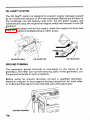
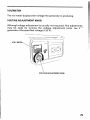
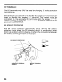
The engine exhaust from this product
contains chemicalsknown to the State
The generator is a potential source of electrical shock if misused. Do
not expose the generator to moisture, rain or snow. Do not let the
generator get wet,and do not operate it with wethands.
Keep this owner's manual handy, so you can refer to it at any time.
This owner's manual is considered a permanent part of the generator
and should remain with the generator if resold.
The information and specifications included in this publication were in
effect at thetimeofapprovalforprinting.HondaMotor
Co., Ltd.
reserves the right, however, to discontinue or change specifications or
design a t any time without notice and without incurring any obligation
be reproducedwithout
whatever. No part of thispublicationmay
written permission.
Congratulationsonyourselectionof
a Hondagenerator. Weare
certain you will be pleased with your purchase of one of the finest
generators on the market.
We want to help you get the best results from your new generator an
to operate it safely. This manual contains the information on how to
do that; please readit carefully.
As you read this manual, you will find information preceded bya
V
I symbol. That information is intendedtohelpyouavoid
damage to your generator, other property, or the environment.
We suggestyoureadthewarrantypolicy
tofullyunderstand
its
coverage and your responsibilities of ownership. The warranty policy
is a separate document that should have been given to you by your
dealer.
Whenyourgenerator
needs scheduledmaintenance, keep in mind
thatyourHondaservicing
dealer is speciallytrainedinservicing
Honda
generators.
Your
authorized
Honda
servicing
dealer
is
dedicated to your satisfaction and will
be pleased to answeryour
questions and concerns.
Best Wishes,
Honda Motor Co., Ltd.
1
A FEW WORDS ABOUT SAFETY
Your safety and the safety
of others are very important. And using
this generator safely is an important responsibility.
To help you make informed decisions about
safety, we have provided
operatingproceduresandotherinformationonlabelsandinthis
manual. This information alerts you to potential
hazards that could
hurt you orothers.
Of course, it is not practical or possible to warn you about all the
hazards associated with operating or maintaining a generator. You
must use your own good judgement.
You will findimportantsafetyinformation
including:
in avarietyofforms,
Safety Labels - on thegenerator.
Safety Messages - preceded by a safety alert s mbol B a n d one
of three signal words,
DANGER, WARNING, or AUTION.
8
These signal words mean:
You WILL be KILLED or SERIOUSLY HURT if
you don't follow instructions.
You CAN be KILLED or SERIOUSLY HURT if
you don't follow instructions.
You CAN be HURT if you don't follow instructions.
Safety Headings - such as IMPORTANT SAFETY
INFORMATION.
Safety Section
Instructions
-
such as GENERATOR SAFETY.
how touse this generator correctly and safely.
This entire book is filled with important safety information
read it carefully.
2
-
please
CONTENTS
SAFETY .......................................................................................................
Safety Label Locations ........................................................................
Safety Information ...............................................................................
COMPONENT IDENTIFICATION ...............................................................
CONTROLS ...............................................................................................
Engine Switch .....................................................................................
Recoil Starter ......................................................................................
Fuel Valve Lever .................................................................................
Choke Lever ........................................................................................
AC Circuit Breaker ..............................................................................
Oil Alert@ System ...............................................................................
Ground Terminal ................................................................................
Volt Meter ...........................................................................................
Voltage Adjustment Knob .................................................................
DC Terminals ......................................................................................
DC Circuit Protector ...........................................................................
GENERATOR USE ....................................................................................
Connections to a Building Electrical System ...................................
Ground System ..................................................................................
Special Requirements ........................................................................
AC Applications ..................................................................................
AC Operation ......................................................................................
DC Operation ......................................................................................
High Altitude Operation.....................................................................
PRE-OPERATION CHECK ........................................................................
Engine Oil ...........................................................................................
Refueling .............................................................................................
Fuel Recommendations .....................................................................
STARTING THE ENGINE .........................................................................
STOPPING THE ENGINE .........................................................................
5
5
7
9
11
11
11
12
12
13
14
14
15
15
16
16
17
17
17
17
18
19
20
22
23
23
24
25
27
28
3
MAINTENANCE .......................................................................................
The Importance of Maintenance
.......................................................
Maintenance Safety ...........................................................................
Emission Control System Information.............................................
Air Index ..............................................................................................
Maintenance Schedule ......................................................................
Engine Oil Change .............................................................................
Air Cleaner Service ............................................................................
Fuel Sediment Cup Cleaning ............................................................
Spark Plug Service .............................................................................
Spark Arrester Maintenance.............................................................
TRANSPORTING/STORAGE ...................................................................
Transporting .......................................................................................
Storage ................................................................................................
TROUBLESHOOTING ..............................................................................
WIRING DIAGRAM ..................................................................................
SPECIFICATIONS .....................................................................................
WARRANTY SERVICE INFORMATION ..................................................
INDEX .......................................................................................................
4
29
29
30
31
33
34
35
36
37
38
40
42
42
43
45
47
48
49
50
SAFETY
SAFETY LABEL LOCATIONS
These labels warn you
of potential hazards that cancauseserious
injury. Read them carefully.
If a label comes off or becomes hard to read, contact your Honda
generator dealer for a replacement.
ISMAllDN SWlTCH I U S IEEN INSTALLED
BY A LIUNPD EUCTMCIU.
/
I
DO NOT USE INDOORS.EXHAUST GAS CONTAINS POISONOUS
(WARNING
CARBON
MONOXIDE.
I.
2TENc10N
ES
NE PAS UTlLlSERDANS UN ENOROIT FERME A CAUSE DU
RISOUE DEMPOISONNEMENT
DU
GAZ.
NO LO USE EN LUGARES CERRADOSPORQUEEL
DE
CARBON0
VENENOSO.
I
MONOXIDE
5
' EM2500X
HONDA MOTOR co., LTD.
CAUTION
1
MADE IN JAPAN ($
DC
WITH RECOMMENDED OIL
BEFORE USING.
FOR DETAILED EXPLANATION.
SEE
THE
OWNER'S
MANUAL.
PHASE
FREQUENCY
RATED
OUTPUT
2.3kVA
VOLTAGE
12V
CURRENT 8.3A
GASOLINE
FUEL
(PETROL)
4
8
I
' E M1800X
HONDA MOTOR co., LTD.
DC
CAUTION
BE SURE TO FILL CRANKCASE
WITH RECOMMENDED OIL
BEFORE USING.
FOR DETAILED EXPLANATION,
SEE THE OWNER'S MANUAL.
\
6
\
MADE IN JAPAN <g>
VOLTAGE
FREQUENCY
RATED
OUTPUT
1.5kVA
MAX.
OUTPUT
1.8kVA
PHASE
VOLTAGE
12V
CURRENT 8.3A
GASOLINE
FUEL
(PETROL)
I
SAFETY INFORMATION
Honda generators are designed to give safe and dependable service if
operated according to instructions. Read and understand this owner’s
manualbeforeoperatingyourgenerator.Youcanhelpprevent
accidents by being familiar with yourgenerator’scontrols,andby
observing safe operating procedures.
Operator Responsibility
Know how to stop the
generator quickly in case of emergency.
Understand the use of all generator controls, output
and connections.
receptacles,
Be sure that anyone who operates the generator receives proper
instruction. Do notletchildrenoperatethegeneratorwithout
parental supervision.
Carbon Monoxide Hazards
Exhaustcontainspoisonouscarbonmonoxide,acolorlessand
odorless gas. Breathing exhaust can cause loss of consciousness
and may leadto death.
If you run the generatorin an area that is confined, or even partially
enclosed, the air you breathe could contain a dangerous amountof
exhaust gas. To keep exhaust gas from accumulating,provide
adequate ventilation.
7
~~~
Electric Shock Hazards
The generator produces enough electric power
shock or electrocution if misused.
t o cause a serious
Using a generator or electrical appliance in wet conditions, such as
rain or snow, or near a pool or sprinkler system, or when your han
are wet, could result in electrocution. Keep the generator dry.
If the generator is stored outdoors, unprotected from the weather,
check all electrical components on the control
panel, before each
use. Moistureor icecan cause amalfunctionorshortcircuit
in
electrical components which could result
in electrocution.
Do not connect to a building electrical system unless an isolation
switch has been installed by
a qualified electrician.
Fire and Burn Hazards
The exhaust system gets hot enough
to ignite some materials.
-Keep the generator at least 3 feet (1 meter) away from buildings
and other equipment during operation.
-Do not enclose the generator in any structure.
-Keep flammable materials away from the generator.
The muffler becomes very hot during operation and remains hot for
a while after stopping the engine.
Be careful not to touch the muffler
while it ishot. Let theenginecoolbeforestoringthegenerator
indoors.
Gasolineisextremelyflammableandisexplosiveundercertain
conditions. Do notsmoke orallowflamesor
sparks wherethe
generator is refueled or where gasoline is stored. Refuel in a wellventilated area with the engine stopped.
Fuel vapors are extremelyflammableandmayigniteafterthe
engine has started. Make sure that any spilled fuel has been wiped
up before starting the generator.
8
COMPONENT
IDENTIFICATION
ENGINE
SWITCH
~
VOLT
METER
AIR CLEANER
SEDIMENT CUP
RECOIL STARTER GRIP
DC CIRCUIT PROTECTOR
ENGINE SERIAL NUMBER
9
FUEL TANK CAP
FUEL
METER
\
. PLUG CAP
\
FRAME SERIAL NUMBER
MUFFLER
*Record theengine
and frameserialnumbersforyourfuture
reference. Refer to these serial numbers when ordering parts, and
when making technicalor warranty inquiries(see page49 ).
Frame serial number:
Engine serial number:
10
CONTROLS
ENGINE SWITCH
To start and stop the engine.
Switch position:
OFF: To stop the engine.
ON: To startandruntheengine.
([
[
ON
ENGINE SWITCH
RECOIL STARTER
To start the engine, pull the starter grip lightly until resistance is felt,
then pull briskly.
riiZEi4
Do not allow the
starter grip tosnap back against theengine. Return it
gently toprevent damage to the starter.
FUEL VALVE LEVER
The fuel valve is located between the fuel tank and carburetor. When
the valve lever is in the ON position, fuel is allowed to flow from the
to the
fuel tank to the carburetor.
Be sure to return the fuel valve lever
OFF position after stopping the engine.
FUEL VALVE LEVER
CHOKE LEVER
The choke is usedto provide proper starting mixture when the engine
iscold. It canbeopenedandclosedbyoperatingthechokelever
manually. Move the choke lever to theCLOSED position to enrich the
mixture for cold starting.
~
CHOKE LEVER
CLOSED
12
AC CIRCUIT BREAKER
The AC circuit breaker will automatically switch OFF if there is a short
circuit or an overload of the generator at the AC receptacle. If the AC
circuit breaker is switched OFF automatically, check that the appliance
is working properly and does not
exceed the rated load capacityof the
AC circuit before switching the
AC circuit breaker ON again.
The AC circuit breaker may be used to switch the generator
AC power
ON or OFF.
13
OIL ALERT@
SYSTEM
The Oil Ale& system is designed
t o prevent engine damage caused
by an insufficient amount of oilin the crankcase. Before the oil level in
the crankcase can fall below a safe limit, the Oil Alert? system will
automatically stop the engine (the engine switch
will remain in theON
position).
If the engine stops and will not restart, check the engine oil level (see
page 23 ) before troubleshooting in otherareas.
OIL FILLER HOLE
,
OIL FILLER CAP
OIL
CAP
FILLER
GROUND TERMINAL
Thegeneratorgroundterminal
is connected totheframeofthe
generator, the metal non-current-carrying parts of the generator, and
the ground terminals of
each receptacle.
Beforeusingthegroundterminal,corsultaqualified
electrician,
electrical inspector or local agency having jurisdiction for local codes
or ordinances that apply to the intended
use of thegenerator.
14
VOLT METER
The volt meter displays the voltage the generator
is producing.
VOLTAGE ADJUSTMENT KNOB
Although voltage adjustmentis usually not required, fine adjustments
may be madebyturningthevoltageadjustmentknob.
Use the
generator at the specified voltage(1 20 V).
VOLT METER
VOLTAGE ADJUSTMENT KNOB
15
DC TERMINALS
The DC terminals may ONLY be used for charging 12 volt automotive
type batteries.
( + ) terminal and
The terminals are colored red to identify the positive
black to identifythenegative
(-1 terminal. The batterymust be
connectedtothegenerator
DC terminalswiththeproperpolarity
(battery positive to generator red terminal and battery negative to the
generator black terminal).
DC CIRCUIT PROTECTOR
The DC circuitprotectorautomaticallyshuts
off the DC battery
chargingcircuitwhenthe
DC chargingcircuitisoverloaded,when
there is a problem with the battery, or when the connections between
the battery and the generator are improper.
DC CIRCUIT PROTECTOR
\
\
OFF
NEGATIVE TERMINAL
(BLACK)
16
POS~TIVETERMINAL
(RED)
GENERATOR USE
CONNECTIONS TOA BUILDINGELECTRICAL SYSTEM
Connections for standby power toa building electrical system must be
madebyaqualifiedelectrician.Theconnectionmustisolatethe
generatorpowerfromutilitypower,andmustcomplywithall
applicable laws and electricalcodes.
Improperconnections
t o a buildingelectricalsystem
can allow
electrical current from the generator
to backfeed into the utility
lines.
Such backfeed may electrocute utility company workers or others
who contact the lines during
a power outage, and the generator may
explode, burn, or cause fires when utility power is restored. Consult
the utility company or
a qualified electrician.
GROUND SYSTEM
Hondaportablegeneratorshaveasystemground
that connects
generator frame components tothe ground terminals in the
AC output
receptacles. The system ground is not connected to the AC neutral
wire. If the generator is tested by a receptacle tester, it will not show
the same ground circuit condition
as for a homereceptacle.
SPECIAL REQUIREMENTS
There maybe
Federal or StateOccupationalSafetyandHealth
Administration (OSHA)regulations,local
codes, orordinancesthat
apply to the intended use of the generator. Please consult a qualified
electrician, electrical inspector, or the local agency having jurisdiction.
In some areas, generators are required to be registered with local
utility companies.
Ifthegeneratorisusedataconstruction
site, theremaybe
additional regulations which must be observed.
17
AC APPLICATIONS
Before connecting an appliance or power cord
to the generator:
Make sure that it is in good working order. Faulty appliances or
power cords cancreate a potential for electricalshock.
If an appliance begins to operate abnormally, becomes sluggish or
stops suddenly, turn it off immediately. Disconnect the appliance,
and determine whether the problem is theappliance, or if the rated
load capacity of the generator
has been exceeded.
Make surethat the electrical ratingof the tool or appliance does not
exceed that of the generator. Never exceed the maximum power
rating of the generator. Power levels between rated and maximum
may be used for no more than
30 minutes.
m
Substantialoverloading
will switch off the AC circuit breaker.
Exceeding the time limit for maximum power operation or slightly
overloading thegenerator may not switch theAC circuit breaker OFF,
but willshorten the service life of the generator.
Limit operation requiring maximum power 30
to minutes.
Maximum poweris:
E M 1800X: 1-8 kVA
EM2500X: 2.5 kVA
For continuous operation, do notexceed the rated power.
Rated power is:
EM1800X: 1.5 kVA
EM2500X: 2.3 kVA
The total power requirements (VA) of all appliances connected must
be considered. Appliance and power
tool manufacturers usually list
ratin'g information near the model number
or serial number.
18
AC OPERATION
1. Start the engine(see page27) and switchON the AC circuit breaker
2. Plug in theappliance.
3. Make sure that the voltmeter indicates the specified voltage.
If not, adjust with the voltage adjustment knob.
Most motorized appliances require more than their rated wattage for
startup.
VOLT METER
AC CIRCUIT BREAKER
VOLTAGE ADJUSTMENT KNOB
Ifthegenerator
is overloaded,orifthereisashortcircuit
in a
connected appliance, the AC circuit breaker will automatically switch
OFF. If theAC circuit breaker is switchedOFF automatically, current to
theconnectedappliance(s)
will shut off. Stoptheengineand
investigate the problem.
Determine if thecause is a short circuit in a connected appliance or an
overload. Correct the problem and restart the generator.
Before connecting an appliance
to the generator, make sure thatit is in
good order and that its electrical rating does not
exceed that of the
generator. Then start the generatorand connect the power cord of the
appliance.
DC OPERATION
The DC terminals may ONLY be used for charging12 volt automotive
type batteries.
Connecting the batterycharging cables:
1. Before connecting the battery charging cable
to a battery that
installed in a vehicle, disconnect the vehicle ground battery cable
from the battery negative
( - ) terminal.
A battery can explode if you do not follow the
seriously injuring anyone nearby.
is
correctprocedure,
Keep all sparks, open flames, and smoking materials away from the
battery.
2. Connectthepositive
( + ) batterychargingcable
tothebattery
positive ( + ) terminal and the other end to the generator positive
(+)
terminal.
3. Connect the negative ( - )
battery charging cable to the generator
negative ( - ) terminal and the other end to the battery negative
(-)
terminal.
NEGATIVE TERMINAL
(BLACK)
4. Start the generator.
20
POSITIVE TERMINAL
(RED)
piEiEil
Do notstartthe
vehicle while thebatterycharging
cables are
connected and the generator is running. The vehicle or the generator
may bedamaged.
An overloaded DC circuit, excessive current draw by the battery, or a
wiring problem will trip the DC circuit protector (PUSH button extends
out). If this happens, wait a few minutes before pushing in the circuit
protector to resume operation. If the circuit protector continues to go
OFF, discontinue charging and see your authorized Honda generator
dealer.
Disconnecting the battery charging cables:
1. Stop the engine.
2. Disconnect the negative( - ) battery charging cable from the battery
negative ( - ) terminal.
3. Disconnect the other endof the negative ( - ) battery charging cable
from thegenerator negative ( - ) terminal.
4. Disconnect the positive ( + ) battery charging cable from the battery
positive (+) terminal.
5. Disconnect the other endof the positive (+) battery charging cable
from the generator positive ( + ) terminal.
6. Connect the vehicle ground battery cable
to the battery negative
(-)
terminal.
NEGATIVE TERMINAL
(BLACK)
POSI'TIVE TERMINAL
(RED)
21
HIGH ALTITUDE OPERATION
At high altitude, the standard carburetor air-fuel mixture
will be too
rich. Performance will decrease, and fuel consumptionwill increase. A
very rich mixture will also foul the spark plug andcause hard starting.
Operation at an altitude that differs from that at which this engine was
certified, for extended periods of
time, may increase emissions.
High altitude performance can be improved by specific modifications
to the carburetor. If you always operate your generator
at altitudes
above 5,000 feet (1,500 meters), have your servicing dealer perform
thiscarburetormodification.This
engine, whenoperatedathigh
altitude with the carburetor modifications for high altitude
use, will
meet each emission standard throughout its useful life.
Even with carburetor modification, engine horsepower will decrease
about 3.5% for each 1,000-foot (300-meter) increasein altitude. The effect of altitude on horsepower
will be greater than thisif no carburetor
modification is made.
When the carburetor has been modified for high altitude operation,
the air-fuel mixture will be too lean for low altitude use. Operation at
altitudes below 5,000 feet (1,500 meters) with a modified carburetor
may cause the engine to overheat
and result in serious engine damage.
Foruse
atlow altitudes, have yourservicing
dealer returnthe
carburetor to original factory specifications.
22
PRE-OPERATION CHECK
ENGINE OIL
Engine oil is a major factor affecting engine performanceand service
life. Non detergent and 2-stroke engine oils will damage the engine
and are not recommended.
Check the oil level BEFORE EACH
USE with the generator on a level
surface and the engine stopped.
Use 4-stroke motor oil that meets
or exceeds the requirements for
API serviceclassification
SJ. Always check the API SERVICE label
on theoilcontainer to besure it inletters
the
cludes
SJ.
SAE VISCOSITY GRADES
l'
Y2O
,20 140 l 6o , *O
-30 -20
-10
0
10 20 30
AMBIENT TEMPERATURE
40°C
SAE IOW-30 is recommended for general, all-temperature use. Other
viscositiesshown
in thechartmaybeusedwhenthe
average
temperature in yourarea is within the indicated
range.
1. Remove the oil filler
cap and wipe the dipstick
clean.
2.Check theoillevelbyinsertingthedipstickintothefiller
without screwingit in.
neck
3. If the level is low, add the recommended oil to the upper mark on
the dipstick.
OIL
FILLER HOLE
OIL
FILLER CAP
OIL
FILLER CAP
23
REFUELING
Fuel tank capacity:
2.91 US gal (11.O 0 ,2.42 Imp gal)
With the engine stopped,
check the fuel level gauge. Refill the fuel tank
if the fuel level is low.
Gasoline is highly flammable and explosive.Youcan
seriously injured when handlingfuel.
be burned or
Stop the engineand keep heat, sparks, and flame away.
Handle fuelonly outdoors.
Wipe upspills immediately.
Refuel in a well-ventillated area with the engine stopped.If the engine
hasbeenrunning,allow
it tocoolfirst.Refuelcarefullytoavoid
spilling fuel.Do not fill above the fuel strainer shoulder. After refueling,
tighten the fuel tank cap securely.
Never refuel the engine inside a building where gasoline fumes may
reach flames orsparks. Keep gasoline away from appliance pilot lights,
barbecues, electric appliances, power tools,etc.
Spilled fuel is not only a firehazard, it causes environmental damage.
Wipe up spills immediately.
\
I
FUEL
LEVEL
24
GAGE
FUEL TANK CAP
FUEL RECOMMENDATIONS
Use unleaded gasoline witha pump octane rating of
86 or higher.
This engine is certified
to operate on unleaded gasoline.
Unleaded gasoline produces fewer engine and spark plug deposits
and extends exhaust system life.
Never use stale or contaminated gasoline or an oiVgasoline mixture.
Avoid getting dirtor water in the fuel
tank.
Occasionallyyouma
hear a light"sparkknock"or"pinging"
(metallic rapping noisewhile operating under heavyloads. This is no
cause for concern.
Y
If sparkknock orpiningoccurs
at a steadyengine speed, under
normal load, change rands of gasoline. If spark knock or pinging
persists, see an authorized Honda generator dealer.
%
pi5E-1
Running the engine with persistent spark knock or pinging can cause
engine damage.
Running the engine with persistentspark knock or pinging is misuse,
and the Distributor's Limited Warrantydoes not cover parts damaged
by misuse.
25
Oxygenated Fuels
Some conventional gasolines are being blended with alcohol or an
ethercompound.
These gasolines are collectivelyreferredto
as
oxygenated fuels. To meet clean air standards, some
areas of the
United Statesand
Canada use oxygenatedfuelstohelpreduce
emissions.
If you use an oxygenated fuel, be sure it is unleaded and meets the
minimum octane rating requirement.
Before using an oxygenated fuel, try to confirm the fuel's contents.
Some states/provinces require this information to
be posted on the
pump.
The following are the EPA approved percentages of oxygenates:
ETHANOL-
(ethyl or grain alcohol) 10% by volume
YOU may use asoline containing up to 10% ethanol
byvolume.
asolinecontainingethanolmay
be
marketed under the name "Gasohol".
8
MTBE-
(methyltertiarybutylether)
15% byvolume
You may use gasoline containing up to 15% MTBE
by volume.
METHANOL-
(methyl or wood alcohol)5% by volume
You
may
use
gasoline
containing
up
to
5%
methanolbyvolume
as long as it alsocontains
cosolventsandcorrosioninhibitorstoprotectthe
fuelsystem.Gasolinecontainingmorethan
5%
methanolbyvolumemay
cause startingand/or
performance problems. It may also damage metal,
rubber, and plastic parts of your fuel system.
If you notice any undesirable operating symptoms, try another service
station or switch to another brand
of gasoline.
Fuel system damage or performance problems resulting from theuse
of an oxygenatedfuelcontainingmorethanthepercentagesof
oxygenates mentioned aboveare not covered under warranty.
26
STARTING THE ENGINE
STARTING THE ENGINE
1. Make sure that the AC circuit breaker is in the OFF position. The
generator may be hard to start aifload is connected.
2. Turn the fuel valve lever to ON
theposition.
3. To start a coldengine, move thechoke lever to theCLOSED position.
To restart a warm
engine, leave the choke lever in the OPEN position.
4. Turn the engine switch to ON
the position.
5.Pull the starter grip lightly until
resistance is felt, then pull briskly.
pC5iG-l
Do not allowthe starter grip tosnap back against theengine. Return it
gently to prevent
damage to the starter or housing.
6. If the choke lever was moved to the CLOSED position to start the
engine, gradually moveit to theOPEN position as the engine warms
UP.
27
STOPPING THE ENGINE
STOPPING THE ENGINE
To stop the engine in 'an emergency, simply turn the engine switch to
the OFF position.
Under
normal
conditions,
use the
following
procedure.
1. Turn theAC circuit breaker to the
OFF position.
Unplug appliances from the generator
AC receptacles.
2. Turn the engine switch to the
OFF position.
Disconnect DC battery chargingcables (see page 21 ).
3. Turn the fuel valve lever to the
OFF position.
28
THE IMPORTANCE OF MAINTENANCE
Good maintenance is essential for safe, economical, and trouble-free
operation. It will also help reduceair pollution.
Improper maintenance, orfailure
t o correct a problembefore
operation, can cause amalfunction in which youcan be seriously hurt
or killed.
Always follow the inspection and maintenance recommendations and
schedules in this owner's manual.
To help you properly care for your generator, the following pages
include a maintenance schedule, routine inspection procedures, and
simple maintenance procedures using basic hand tools. Other service
tasks that are more difficult, or require special tools, are best handled
by professionals andare normally performed by a Honda technician or
other qualified mechanic.
The maintenance schedule applies to normal operating conditions. If
you operate your
generator
under
severe conditions,
such
as
sustainedhigh-load
orhigh-temperatureoperation,oruse
it i n
unusually wet or dusty conditions, consult your servicing dealer for
recommendations applicableto your individualneeds and use.
Remember that your servicingdealer knows your generator best and
is fully equipped to maintain and repair
it.
Toensurethebestquality
and reliability,useonly
new, genuine
Honda parts or their equivalents for repair or replacement.
Maintenance, replacement, or repair of the emission control devices
and systems may be performed by any engine repair establishment
individual, using partsthat are "certified" t o EPA standards.
29
MAINTENANCE SAFETY
Some of the most important safety precautions follow. However, we
cannotwarnyouofeveryconceivable
hazard that canarise
in
performing maintenance. Only you
can decide whether or not you
should perform a given
task.
Failure to properly follow maintenance instructions and precautions
can causeyou to be seriously hurt or killed.
Always followthe procedures and precautions in theowner's manual.
Safety Precautions
Make sure the engine is off before you begin any maintenance or
repairs. This will eliminate several potential hazards:
-Carbon monoxide poisoning from engine exhaust.
Be sure there is adequate ventilation whenever you operate the
engine.
-Burns from hot parts.
Let the engine and exhaust system cool before touching.
-Injury from moving parts.
Do not run the engine unless instructed toso.do
Read the instructions before you begin, and make sure you have the
tools and skills required.
Toreducethepossibilityoffireorexplosion,becarefulwhen
workingaroundgasoline.Useonlyanonflammablesolvent,not
gasoline, to clean parts. Keep cigarettes, sparks, and flames away
from all fuel-relatedparts.
30
EMISSION CONTROL SYSTEM INFORMATION
Source of Emissions
Thecombustionprocessproducescarbonmonoxide,oxidesof
nitrogen, and hydrocarbons. Control of hydrocarbons and oxides of
nitrogenisveryimportant
because, undercertainconditions,they
react to form photochemical smog when subjected to sunlight. Carbon
monoxide does notreact in thesame way, but it is toxic.
Honda utilizes lean carburetor settings and other systems
the emissions
of
carbon
monoxide,
oxides
of
nitrogen,
and
hydrocarbons.
to reduce
The U.S. and California Clean Air Acts
EPA andCaliforniaregulationsrequire
all manufacturers to furnish
written instructions describing the operation and maintenance of emission control systems.
The following instructions and procedures must be followed in order
to keep the emissions from your Honda engine within the emission
standards.
Tampering and Altering
Tampering with or altering the emission control system may increase
emissions beyond the legal
limit. Among those acts that constitute
tampering are:
Removal or alteration of any part of the
systems.
intake,fuel,
or exhaust
Alteringordefeatingthegovernorlinkageorspeed-adjusting
mechanism to cause theengine
to operateoutsideitsdesign
parameters.
31
Problems That May Affect Emissions
If you are aware of any of the following symptoms, have your engine
inspected and repaired by your servicing dealer.
Hard starting or stalling after starting.
Rough idle.
Misfiring or backfiring under load.
Afterburning (backfiring).
Black exhaust smoke or high fuel consumption.
Replacement Parts
The emission control systems on your Honda engine were designed,
built,andcertified
toconformwith
EPA andCaliforniaemission
regulations.
We
recommend
the
use of
genuine
Honda
parts
whenever
you
have
maintenance
done.
These original-design
replacement parts are manufactured to the same standards
as the
original parts, so you can be confident of their performance. The use
of replacement parts that are not of the original design and quality
may impair the effectiveness of your emission control system.
A manufacturer of an aftermarket part assumes the responsibility that
the
part
will
not
adversely
affect
emission
performance.
The
manufacturer or rebuilder of the part must certify that use of the part
will not result in
a failure of the engine to comply with emission
regulations.
Maintenance
Follow the maintenance schedule on page
34 . Remember that this
schedule is based on the assumption that your machine will be used
for its designedpurpose.Sustainedhigh-load
or high-temperature
operation, or use in unusually wet or dusty conditions, will require
more frequent service.
32
I
AIR INDEX
An Air Index Information hang tag/label is applied to engines certified
to an
emission
durability
time period
in
accordance withthe
requirements of the California Air
Resources Board.
The bar graph is intended to provide you, our customer, the ability to
compare the emissions performance of available engines. The lower
the AirIndex, the less pollution.
The durability description is intendedto provide you with information
relating to the engine's emissiondurabilityperiod.Thedescriptive
term indicates the useful-life period for the engine's emission control
system. See your Emission
Control
Warranty
foradditional
information.
I
DescriptiveTerm
Applicable to Emissions Durability Period
Moderate
50 hours (0-65 cc)
125 hours (greater than65 cc)
Intermediate
125 hours (0-65 cc)
250 hours (greaterthan 65 cc)
I
I
Extended
I
300 hours (0-65 cc)
500 hours (greater than65 cc)
The Air Index Information hang tag must remain the
on generator until
it is sold. Remove the hang tag before operating the generator.
33
MAINTENANCE SCHEDULE
\
REGULAR SERVICEPERIOD (3)
ITEM
Perform at every indicated month
oor p e r a t i n gh o uirn t e r v a l ,
whichever comes first.
I Engine oil
Check level
Change
I Air
Check
Clean
filter
First
Each
use
or
20 Hrs.
0
l
o
Every Every
year
or or or
300 Hrs.
3 months 6months
month
1
0
100 Hrs.
I
I
I
I
(
50 Hrs.
0
1
I
I
I
O(1)
Replace
O(*)
B Clean
Sediment
cup
B
Spark plug
arrester
Clean
Spark
D
Idle w e e d
D clearance
Valve
Check-adjust
D
B
line
D
Fueltankandfilter
Fuel
NOTE:
34
0
0
Check-adjust
Replace
0
0
Check-adiust
Clean
Clean
Check
I
I
I
,
0
17)
->-I
I
O(2)
Every 500 Hrs (2) Combustion chamber
I
O(2)
1
Every 2 years (Replace if necessary) (2)
0 Emissionrelateditems.
(*)Replace paper element type only.
(1)Service more frequently when useddusty
in areas.
(2)These items should be serviced by an authorized Hondadealer, unless the owner
has the propertools and is mechanically proficient.
(3)Forcommercial use, log hours of operation to determine proper maintenance
intervals.
E
ENGINE OIL CHANGE
Drain the oil while the engine
draining.
is warm to assure rapid and complete
1. Remove the oil drain plug and sealing washer, remove the oil filler
cap, and drain the oil.
OIL
DRAIN
OIL FILLER CAP
PLUG
2.Reinstall the oil drain plug and sealing washer. Tighten the plug
securely.
3. Refill with the recommended oil
level.
(see page 23 ) and check the oil
Oil capacity: 0.63US qt (0.60 !2,0.53Imp qt)
4. Reinstall the oil fillercap and tighten it securely
Wash your hands with soap and waterafter handling used oil.
Improper disposal of engine oil can be harmful tothe environment. If
you change your own oil, please dispose of it properly. Put it in a
sealed container, and take it to a recyclingcenter. Do not discard it in a
trash bin or dump
it on the ground.
AIR CLEANER SERVICE
A dirty air cleaner will restrict air flow to the carburetor. To prevent
carburetor malfunction, service the air cleaner regularly. Service more
frequently when operating the generator in extremely dusty
areas.
Using gasoline orflammable solvent to clean the air filter can cause a
fire or explosion. Use only soapy water or nonflammable solvent.
1
NOTICE
Never run the generator without the air filter. Rapid engine wear will
result.
1. Unsnap the air cleaner cover clips
andremovetheaircleaner
cover,
and remove the element.
2. Wash the air filter in a solution
household
detergent
and
warm
water,
then
rinse
thoroughly,
or
wash
in
nonflammable
or
high
flashpointsolvent.Allowtheair
filter to dry thoroughly.
AIR CLEFNER COVER
of
3. Soak the air filterin clean engine oil
and squeeze out the excess oil. The
engine will smoke
during
initial
startup if too much oil is left in the
air filter.
4. Reinstall the air filter element and
the cover.
AIR FILTER ELEMENT
36
FUEL SEDIMENT CUP CLEANING
The sediment cup prevents dirt or water which may in
bethe fuel tank
from entering the carburetor. If the engine
has not been run fora long
time, the sediment cup should be
cleaned.
1. Turn the engine switch to OFF
the position.
2. Turn the fuel valve lever to OFF
the position.
3. Remove the sediment cup by turning
it counterclockwise.
4.Clean the sediment cup and O-ring
point solvent.
in nonflammable or high flash
5. Reinstall the O-ring and sediment
cup.
6. Turn the fuel valve lever
ON and check for leaks.
FUEL VALVE LEVER
I
.SEDIMENTCUP
O-RING
SEDIMENT CUP
37
SPARK PLUG SERVICE
In order to service the spark plug, you will needa spark plug wrench
(commercially available).
Recommended spark plugs:
BPRGES (NGK)
W20EPR-U (DENSO)
TO ensure proper engine operation, the spark plug must
gapped and free of deposits.
be properly
If the engine has been running, the muffler willbe very hot. Be careful
not to touch the muffler.
1. Remove the spark plugcap.
2. Clean any dirt from around t h e spark plug base.
3. Use a spark plug wrench to remove the
spark plug.
SPARK PLUG WRENCH 1
“PLUG
CAP
4.Visually inspect the spark plug. Discard it if the insulator is cracked
or chipped. Clean the spark plug with a wire brush if
it is to be
reused.
5. Measure
the
plug
gap
with
a feeler
gauge.
Correct as necessary bycarefully
bending the side electrode.
The gap should be:
0.028-0.031 in (0.70-0.80 mm)
38
0.028-0.031 in
(0.70-0.80 mm)
6. Check that the spark plug washer is in good condition, and thread
the spark plug in byhand to prevent cross-threading.
7.After the spark plug is seated, tighten with a spark plug wrench to
compress the washer.
If installing a new spark plug, tighten 1/2 turn after the spark plug
If reinstallingausedsparkplug,
seats tocompressthewasher.
tighten 1/8-1/4 turn after the
spark plug seats to compressthe
washer.
m
The spark plug must besecurely tightened. An improperly tightened
spark plug can becomevery hot and could damage the engine.
Never use spark plugs which have an improper heat range. Use only
the recommended spark plugs or equivalent.
8. Reinstall the spark plug cap on the spark plug securely.
39
SPARK ARRESTER MAINTENANCE
If the generatorhas been running, the muffler willbe very hot. Allow it
to cool before proceeding.
The spark arrester must
efficiency.
be serviced every 100 hours to maintain its
Clean the spark arresteras follows:
1. Remove the five6 m m bolts, and remove the muffler protector.
MUFFLER PROTECTOR
2. h m o v e the two 8 mm bolts a t the exhaust pipe and 8 mm bolt at
the muffler stay.
Remove the muffler and
spark arrester.
8 mrn BOLTS
SPARK ARRESTER
8 rnrn BOLT
MUFFLER
40
3. Usea brush to remove carbon deposits from the spark arrester
screen.
4. Inspect thescreen for breaks or tears and replace it if necessary.
5.Check the muffler gasket; replace if damaged. Reinstall the muffler
gasket, the spark arrester, the muffler and the muffler protector in
the reverse order of removal.
41
TRANSPORTIMG/STORAGE
TRANSPORTING
If the generator has been used, allow it cool for a t least 15 minutes
before loading the generator on the transport vehicle. A hot engine
and exhaust system can burn you and can ignite some material.
When transporting the generator, turn the engine switch and the fuel
valve lever OFF, and keep the generator level to reduce the possibility
of fuelleakage.
Take care not to drop or
strike the generator when transporting.
Do not
place heavy objects on the generator.
42
STORAGE
Before storing the unit for an extended period:
1. Be sure the storagearea is free ofexcessive humidity and dust.
2. Service according to the table below:
RECOMMENDED SERVICEPROCEDURE TO
PREVENT HARDSTARTING
Less than 1 month No preparation required
1 to 2 months
Fill with freshgasolineandaddgasoline
conditioner *.
Fill with freshgasolineandaddgasoline
2 months to1 year conditioner *.
Drain the carburetor float bowl. (page
44).
Drain the fuel sediment
cup. (page 37).
Fill with freshgasolineandaddgasoline
conditioner *.
Drain the carburetor float bowl. (page
44).
1 year or more Drain the fuel sediment
cup. (page 37).
Remove the spark plug. Put a tablespoon of
engine oil into the cylinder. Turn the engine
slowly with the starter grip to distribute the
oil. Reinstall the spark plug.
Change the engine oil. (page35).
After removal from storage, drain the stored
gasolineinto asuitablecontainer,and
fill
with fresh gasoline before starting.
* Use gasoline conditioners thatare formulated to extend storage
life.
Contact your authorized Honda generator dealer for conditioner
recommendations.
STORAGE TIME
43
Storage Procedure
1.Drain the fuel
tank, the carburetor and the fuel sediment cup.
a. Removethe carburetor drain screw.
b.Drain the gasoline from the carburetor into a suitable container.
c. Install and tighten the carburetor drain screw.
d.Turn the fuel valve lever off and drain the fuel sediment cup.
e.Turn the fuel valve lever on anddrain the gasoline from the fuel tank into a
suitable container.
f. Install and tighten the fuel sediment cup securely.
g.Turn the fuel valve lever off.
Gasoline is highly flammable and explosive. You can
seriously injured when handling fuel.
be burned or
Keep heat, sparks, and flame away.
Handle fuel only outdoors.
Wipe up spillsimmediately.
DRAIN SCREW
2.Change the engine oil (page
35).
3.Removethesparkplug,andpouraboutatablespoonofclean
engine oil into the cylinder.Crank the engine several revolutions to
distribute theoil, then reinstall thespark plug.
4.Slowly pull the starter grip until resistance is felt. At this point, the
piston is comin up on its compression stroke and both the intake
and exhaust va ves are closed. Storing the engine in this position
will help to protect
it from internal corrosion.
s
44
Add
TROUBLESHOOTING
When the enginewill not start:
~
Is there fuel in the
tank?
NO
Refill the fueltank.
IYES
oil
enough
Is there
in
I
YES
Is there
spark
a
f r o mt h es p a r k
plug?
-
Still NO spark
NO R e p l a c et h e
sparkplug.
Be
sure
there is no
spilled fuel around the
spark plug. Spilled fuel
may ignite.
YES
1
Is the fuel reaching NO
the carburetor?
YES
t
Iftheenginestill
does not start, take
the generator to an
authorized
Honda
generator dealer.
I
-
Take'the generator
t o an
authorized
Honda
generator
dealer.
To check:
1 ) Removethespark
plugcapand
clean
anydirtfromaround
the spark plug.
2) Removethespark
plugandinstallthe
spark
plug
in
the
plug cap.
3) Set theplugside
e l e c t r o d eo nt h e
cylinder head.
4) Cranktheengine,
sparks shouldjump
across the gap.
Cleanthefuel
sediment cup.
To check:
1) T u r no f ft h ef u e l
v a l v el e v e ar n d
r e m o v et h ed r a i n
screw.
2) T u r no nt h ef u e l
v a l v lee v e rF. u e l
should flow from the
drain.
~
DRAIN SCREW
45
Appliance does notoperate:
Is the AC circuit breaker
ON?
NO
Turnthe
AC circuit breaker
ON.
NO DEFECTS
Check the electrical appiance or equipment for
any defects.
Take thegeneratorto
an
authorizedHondagenerator
dealer.
Replace the electrical appliance or equipment.
.Take
the
electrical
ap-
DEFECTS
pliance or e q u i p m e n t to a n
electrical shop for repair.
No electricity at theDC terminals:
Is the DC circuit protector
Turn the DC circuit protector
on.
NO
on?
I
I
YES
46
Take thegeneratortoan
authorizedHondagenerator
dealer.
CONTROL BOX BLOCK
-
1
-
;ROUND
TERMlNlAL
I
4
OIL LEVEL SWITCH
I
.
GENERATOR BLOCK
ENGINE BLOCK
SPECIFICATIONS
Dimensions
Model
Power product description code
Length
Width
Height
Dry weight
EM1800X
EM2500X
EZCK
EZCN
19.9 in (505 mm)
16.5 in (420 m m )
16.5 in (420 mm)
91.5 Ibs (41.5 kg) I 98.1 Ibs (44.5 kg)
Engine
Model
Engine Type
Displacement
[Bore x Stroke]
Compression Ratio
Engine Speed
Cooling System
Ignition System
Oil Capacity
Fuel Tank Capacity
Spark Plug
GX160K1
4-stroke, overhead valve, single cylinder
9.9 cu-in (163 cm3)
(2.7 X 1.8 in (68 X 45 mm)]
8.5 : 1
3,600 rpm
Forced air
Transistorized magneto
0.63 US qt (0.60 0,0.53 Imp qt)
2.91 US gal (11.0 0 ,2.42 Imp gal)
BPR6ES (NGK)
W20EPR-U (DENSO)
Generator
Model
EM1800X
Type
Rated voltage
Rated frequency
Rated Ampere
Rated Output
Maximum Output
AC output
12.5 A
1.5 kVA
1.8 kVA
19.2 A
2.3 kVA
2.5 kVA
.~
Tune-uD
, Seecifications
ITEM
SPECIFICATION
0.028-0.031 in (0.70-0.80 r n r n )
Spark plug gap
Valve clearance
IN: 0.15t0.02 mm (cold)
EX: 0.20t0.02 mm (cold)
Other
specifications
I
No
other
adjustments
~
EM2500X
A
120 v
60 Hz
~
~
I
1
MAINTENANCE
Refer to page: 38
See your authorized
Hondadealer
needed.
NOTE:
Specifications may vary according to the types, and are subject
change without notice.
48
to
WARRANTY SERVICE INFORMATION
Servicing dealership personnelare trained professionals. They should
be able to answer any question you may have. If you encounter
a
problem that your dealer does not solve to your satisfaction, please
discuss it with the dealership's management. The Service Manager or
General Manager can help. Almost all problems
are solved in this way.
If you. aredissatisfied with thedecisionmade
by thedealership's
management,
contact
the
Honda
Power
Equipment
Customer
Relations Office. You can write to:
American Honda MotorCo., Inc.
Power Equipment Division
Customer Relations Office
4900 Marconi Drive
Alpharetta, Georgia 30005-8847
telephone:
Or
(770)
497-6400
When you write orcall, please give us this information:
Model and serial number(see pages 9and 10)
Name of dealer who sold the generator to you
Name and address of
dealer who services your generator
~
I
Date of
purchase
Your name,address,
andtelephonenumber
A detailed description of the problem
49
INDEX
COMPONENT IDENTIFICATION ............................................................... 9
CONTENTS ................................................................................................. 3
CONTROLS ............................................................................................... 11
AC Circuit Breaker ............................................................................... 13
12
Choke Lever ........................................................................................
DC Circuit Protector ........................................................................... 16
16
DC Terminals ......................................................................................
Engine Switch..................................................................................... 11
Fuel Valva Lever ................................................................................. 12
14
Ground Terminal ................................................................................
Oil Alert@ System...............................................................................
14
Recoil Starter ...................................................................................... 11
15
Voltage Adjustment Knob .................................................................
Volt Meter ........................................................................................... 15
17
GENERATOR USE ....................................................................................
;.........................
18
AC Applications ........................................................
19
AC Operation ......................................................................................
Connections t o a Building Electrical System...................................
17
20
DC Operation ......................................................................................
17
Ground System ..................................................................................
:
........................
22
High Altitude Operation............................................
Special Requirement .........................................................................
17
MAINTENANCE ....................................................................................... 29
Air Cleaner Service ............................................................................ 36
Air Index ..............................................................................................
33
Emission Control System Information.............................................
31
Engine Oil Change .............................................................................
35
Fuel Sediment Cup Cleaning ............................................................
37
Importance of Maintenance ..............................................................
29
Maintenance Safety ........................................................................... 30
Maintenance
Schedule ...................................................................... 34
Spark Arrester Maintenance .............................................................
40
Spark Plug Service ............................................................................. 38
PRE-OPERATION CHECK ........................................................................ 23
Engine Oil ...........................................................................................
23
Fuel Recommendations ..................................................................... 24
Refueling ............................................................................................. 23
50
.
SAFETY .......................................................................................................
Safety Information ...............................................................................
Safety Label Locations ........................................................................
SPECIFICATIONS .....................................................................................
STARTING THE ENGINE .........................................................................
STOPPING THE ENGINE .........................................................................
TRANSPORTING/STORAGE ...................................................................
Storage ................................................................................................
Transporting .......................................................................................
TROUBLESHOOTING ..............................................................................
WARRANTY SERVICE INFORMATION ..................................................
WIRING DIAGRAM ..................................................................................
5
7
5
48
27
28
42
43
42
45
49
47
51
MEMO
52