1
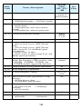
HITACHI
L100-M Series Inverter
Quick Reference Guide
• Single-phase Input
100V Class
Hitachi Industrial Equipment Systems Co., Ltd.
Manual No. NB5741XD • December 2003
Caution: Be sure to read the L100 Inverter Manual and
follow its Cautions and Warnings for the initial product
installation. This Quick Reference Guide is intended for
reference use by experienced users in servicing existing
installations.
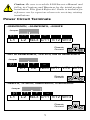
Power Circuit Terminals
–002NFE/NFU, –004NFE/NFU, –005NFE
Jumper
(/)
L1
+1 +
–
L2 N/L3 U/T1 V/T2 W/T3
Chassis
Ground
–007 to 022NFE/NFU, –037LFU, 004 to 040HFE/HFU
Jumper
(/)
+1
L1
+
–
L2 N/L3 U/T1 V/T2 W/T3
Chassis
Ground
–055LFU, –075LFU, 055HFE/HFU, 075HFE/HFU
Jumper
(/) +1 +
–
L1 L2 N/L3 U/T1 V/T2 W/T3
Chassis
Ground
1
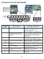
Control Circuit Terminals
Logic
inputs
L
5
4
3
2
1 P24
H O OI L FM CM2 12 11
Analog
inputs
Analog
outputs
Logic
outputs
AL0 AL1 AL2
Alarm
relay
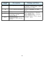
Terminal
Name
Description
Ratings and Notes
P24
+24V for logic inputs
24VDC supply, 30 mA max.
(Notes: Do not use for
network power
Do not short to terminal L)
1, 2, 3, 4, Intelligent (program5
mable) discrete logic
inputs
27VDC max. (use P24 or an
external supply referenced to
terminal L), 4.7kΩ input
impedance
11, 12
Discrete logic outputs
50 mA max. ON current,
27 VDC max. OFF voltage
L (top
row)
GND for logic inputs
Sum of input 1 to 5 currents
(Note: Do not ground)
CM2
Common for logic
outputs
100 mA max for sum of
terminals 11 and 12 currents
PWM output
0 to 10VDC, 1 mA max.,
50% duty cycle
FM
L (bottom Common for analog
row)
inputs
OI
Analog input, current
2
Sum of OI, O, and H
currents (return)
4 to 19.6 mA range, 20 mA
nominal
Terminal
Name
Description
Ratings and Notes
O
Analog input, voltage
0 to 9.6 VDC range, 10VDC
nominal, 12VDC max., input
impedance 10 kΩ
H
+10V analog reference 10VDC nominal, 10 mA
max.
AL0
Relay common contact Contact rating
AL1
Relay contact,
normally closed
during RUN
AL2
Relay contact,
normally open during
RUN
3
Max resistive load = 250VAC,
2.5A; 30VDC 3A;
Max inductive load = 250VAC,
0.2A; 30VDC 0.7A
Minimum load = 5VDC 100mA,
100VAC, 10mA
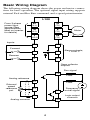
Basic Wiring Diagram
The following wiring diagram shows the power and motor connections for basic operation. The optional signal input wiring supports
external Fwd and Rev Run command, and a speed potentiometer.
L100
From 3-phase
power input
source (See
specifications
label on inverter
for details)
U
R
(T1)
(L1)
S
V
(L2)
(T2)
T
W
(N/L3)
(T3)
P24
AL1
1
AL0
2
AL2
Motor
Inputs:
Forward
Alarm contacts,
1 Form C
Reverse
Open collector
outputs:
Run signal
12
Load
Analog reference
H
External
speed
reference
pot.
Load
O
11
Frequency
arrival signal
Logic output
common
L
CM2
Analog common
4
Inverter Keypad Operation
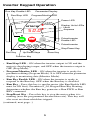
Run Key Enable LED
Run/Stop LED
Parameter Display
Program/Monitor LED
Power LED
POWER
HITACHI
5 0.0
RUN
PRG
RUN
Hz
A
STOP
RESET
MAX
MIN
FUNC. 1
2
Display Units LEDs
Hertz
Amperes
Potentiometer
Enable LED
Potentiometer
STR
Stop/Reset Key
Run Key
Up/Down Keys
Store Key
Function Key
• Run/Stop LED – ON when the inverter output is ON and the
motor is developing torque, and OFF when the inverter output is
OFF (Stop Mode).
• Program/Monitor LED – ON when the inverter is ready for
parameter editing (Program Mode). It is OFF when the parameter
display is monitoring data (Monitor Mode).
• Run Key Enable LED – ON when the inverter is ready to
respond to the Run key, OFF when the Run key is disabled.
• Run Key – Press this key to run the motor (the Run Enable LED
must be ON first). Parameter F_04, Keypad Run Key Routing,
determines whether the Run key generates a Run FWD or Run
REV command.
• Stop/Reset Key – Press this key to stop the motor when it is
running (uses the programmed deceleration rate). This key will
also reset an alarm which has tripped.
(continued, next page...)
5
• Potentiometer – Allows an operator to directly set the motor
speed when the potentiometer is enabled for output frequency
control.
• Potentiometer Enable LED – ON when the potentiometer is
enabled for value entry.
• Parameter Display – A 4-digit, 7-segment display for parameters and function codes.
• Display Units: Hertz/Amperes – One of these LEDs will be ON
to indicate the units associated with the parameter display.
• Power LED – ON when the power input to the inverter is ON.
• Function Key – This key is used to navigate through the lists of
parameters and functions for setting and monitoring parameter
values.
• Up/Down Keys – Use these keys alternately to move up or down
the lists of parameter and functions shown in the display, and to
increment/decrement values.
• Store Key – When the unit is in Program Mode and the operator
has edited a parameter value, press the Store key to write the new
value to the EEPROM.
6
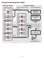
Keypad Navigation Map
Monitor Mode
Program Mode
Display data
o.0
Select Parameter
Edit Parameter
powerdown
Store as
powerup
default
FUNC.
d 09
1
c 91
2
1
d 01
1
c 01
2
1
C ––
1
2
b ––
1
FUNC.
1
1
2
1
2
A 98
2
1
FUNC.
2
2
Edit
FUNC.
1 2 3.4
b 01
2
F 04
1
2
b 89
A ––
1
Increment/
decrement
value
2
FUNC.
STR
Write data
to
EEPROM
A 01
2
F 01
Return to
parameter list
7
Powerup Test
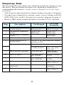
The Powerup Test procedure uses minimal parameter settings to run
the motor. The procedure describes two alternative methods for
commanding the inverter: via the inverter keypad, or via the logic
terminals.
• Check power input and motor output wiring (see page 4 diagram).
• If using logic terminals for testing, verify correct wiring on [P24],
[FW], [H], [O], and [L] (bottom row) per the diagram on page 4.
• Reverse [RV] input wiring (defaults to terminal [2]) is optional.
Step
Description
Via Keypad
Via Logic
Terminals
1
Set speed command
source setting
A_01 = 00
(keypad pot.)
A_01 = 01,
[H–O–L] input
2
Set Run FW command
source
A_02 = 02
(Run key)
A_02 = 01,
[FW] input
3
Set Run REV command
source
—
C_02 = 01,
[RV] input
4
Set motor base freq.
A_03 = 60
5
Set keypad display to
monitor freq.
Access D_01, press Func key, display
will show 0.0
Perform safety check
Disconnect load from motor
6
Turn keypad pot.
to MIN position
Ensure voltage on
[O]—[L] terminals= 0V
7
Run Forward command
Press Run key
Turn ON the
[FW] terminal
8
Increase speed
Rotate keypad
pot. CW dir.
Increase voltage
at [O]
9
Decrease speed
Rotate keypad
pot. CCW dir.
Decrease voltage
at [O]
10
Stop motor
Press Stop key
Turn OFF the
[FW] terminal
11
Run Reverse command
(optional)
—
Turn ON the [RV]
terminal
12
Stop motor
—
Turn OFF the
[RV] terminal
8
Error Codes
The L100 series inverters will trip on over-current, over-voltage, and
under-voltage to protect the inverter. The motor output turns OFF,
allowing the motor to free-run to a stop. Press the Stop/Reset key to
reset the inverter and clear the error.
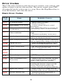
Basic Error Codes
Error
Code
Name
Probable Cause(s)
E01
Over current event while
at constant speed
E02
Over current event during
deceleration
E03
Over current event during
acceleration
• Inverter output was short-circuited
• Motor shaft is locked
• Load is too heavy
• A dual-voltage motor is wired
incorrectly
Note: The L100 will over current trip
at nominally 200% of rated current
E04
Over current event for
other conditions
• DC braking power(A_54) set too
high
• Current transformer / noise error
E05
Overload protection
• Motor overload is detected by the
electronic thermal function
E07
Over voltage protection
• DC bus voltage exceeds a threshold,
due to regenerative energy from motor
E08
EEPROM error
• Built-in EEPROM memory experienced noise, high temperature, etc.
E09
Under-voltage error
• DC bus voltage decreased enough to
cause a control circuit fault
CPU error
• Built-in CPU had internal error
External trip
• [EXT] input signal detected
USP (Unattended Start
Protection)
• When (USP) was enabled, an error
occurred when power was applied
while a Run signal was present
E14
Ground fault
• A ground fault was detected
between the inverter output and the
motor. This feature protects the
inverter, and does not protect humans.
E15
Input over-voltage
• Input voltage was higher than the
specified value, 60 sec. after powerup
E21
Inverter thermal trip
• Inverter internal temperature is
above the threshold
E11
E22
E12
E13
9
Error
Code
E35
---
Name
Probable Cause(s)
Thermistor
• Thermistor input, [THM] and [L], is
over the temp. threshold
Under-voltage (brownout) with output shutoff
• Low input voltage caused the
inverter to turn OFF the motor output
and try to restart. If unsuccessful, a
trip occurs.
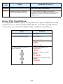
Error Trip Conditions
Use function code D_08 to access the error trip conditions for the
current error as shown in the table below. Use the Up and Down
arrow keys to scroll through the trip condition parameters.
Step
Display
08
1. Access D_08
d
2. Press Function Key
If no error:
___
If error exists:
Exx
(error code)
3. Press Up/Dn key (if
error exists)
Output frequency at
trip point:
10.0
1
Motor current at trip
point:
2
DC bus voltage at trip
point:
0.025
189.8
10
Restoring Factory Default Settings
Action
Display
Press FUNC. , 1 or 2
needed.
Press
as
FUNC. .
1
Press/hold
until...
b
--
b
01
b
85
To change country code, press 1
Press
FUNC. .
Press 2 .
84
01
Press/hold
.
FUNC. ,
1 , and
or 2
b
Press 1 .
Country code for
initialization selected
00 = Japan
01 = Europe
02 = United States
85
00
STR
First “B” Group parameter
b
Press FUNC. .
Press
“B” Group selected
02
Press FUNC. . If setting is
correct, then skip next step.
Function/Parameter
b
84
b
84
d
00
to set;
STR
to store.
Country code for
initialization selected
Initialization function
selected
0 = disable initialization,
clear trip history only
1 = enable initialization
Initialization now
enabled to restore all
defaults
First part of key sequence
2 . Do not release yet.
STOP
Press/hold RESET
(STOP) for
3 seconds, then release.
Now release the all keys
together, only after “D_00”
display begins blinking.
Initialization is complete.
EU
USA
JP
d 01
11
Final part of special
sequence, “D_00” is
flashing
Default parameter
country code shown
during initialization
Function code for output
frequency monitor shown
Note: After initializing the inverter, use the Powerup Test
on page 8 to get the motor running again.
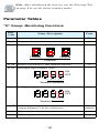
Parameter Tables
“D” Group: Monitoring Functions
Func.
Code
Name / Description
Units
D_01
Output frequency monitor
D_02
Output current monitor
A
D_03
Rotation direction monitor
—
Forward
Hz
Stop
Reverse
Direction
D_04
Process variable (PV), PID feedback monitor
%
D_05
Intelligent input terminal status
—
ON
OFF
5 4
3 2
1
Terminal Numbers
D_06
Intelligent output terminal status
—
ON
OFF
AL 12 11
Terminal Numbers
D_07
Scaled output frequency monitor
(output frequency x B_86 scale factor)
D_08
Trip event monitor
—
D_09
Trip history monitor
—
12
Userdefined
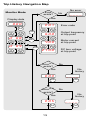
Trip History Navigation Map
No error
Monitor Mode
Error
exists?
o.0 0
E 07
FUNC.
1
FUNC.
1
2
FUNC.
Output frequency
at trip point
2
4.0 0
2
d 09
1
1
FUNC.
Error code
2
6 0.0
2
d 08
____
Yes
Display data
1
No
1
Motor current
at trip point
2
2 7 0.0
Error(n-1)
exists?
DC bus voltage
at trip point
No
No
history
Yes
E 03
____
FUNC.
Error(n-2)
exists?
Yes
E 05
FUNC.
13
FUNC.
No
No
history
____
FUNC.
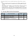
Parameter tables for user-settable functions follow these conventions:
• Some parameters specify an option code. Where applicable, the
options codes will be in a bulleted list in the Name/Description
column.
• The default values apply to all models unless otherwise noted for
each parameter... –FE (Europe) / – FU (U.S.) / –FR (Japan).
• Some parameters cannot be edited during Run Mode, and certain
Software Lock settings (B_31) can prohibit all edits. If in doubt,
place the inverter in Stop Mode or consult the inverter manual for
details.
“F” Group: Main Profile Parameters
Func.
Code
Name / Description
Default
Value
F_01
Output frequency setting
0.0
F_02
Acceleration (1) time setting
10.0
F_03
Deceleration (1) time setting
10.0
F_04
Keypad Run key routing
• 00 Forward
• 01 Reverse
14
00
Set
Value
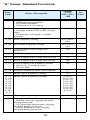
“A” Group: Standard Functions
Func.
Code
Name / Description
Default
Value
–FE / –FU /
–FR
A_01
Frequency source setting
• 00 Keypad potentiometer
• 01 Control terminal
• 02 Function F_01 setting
01 / 01 / 00
A_02
Run command source setting
• 01 Input terminal FW or RV (assignable)
• 02 Run key on keypad, or digital
operator
01 / 01 / 02
A_03
Base frequency setting
50.0 / 60.0 /
60.0
A_04
Maximum frequency setting
50.0 / 60.0 /
60.0
A_11
O/OI–L input active range start
frequency
0.0
A_12
O/OI–L input active range end frequency
0.0
A_13
O/OI–L input active range start voltage
0
A_14
O/OI–L input active range end voltage
100
A_15
O/OI–L input start frequency enable
• 00 Use A_11 starting value)
• 01 Use 0 Hz
01
A_16
External frequency filter time constant
8
A_20
Multi-speed frequency setting
A_21 Multi-speed frequency settings
A_22
A_23
A_24
A_25
A_26
A_27
A_28
A_29..
..A_35
0
0/0/5
0 / 0 / 10
0 / 0 / 15
0 / 0 / 20
0 / 0 / 30
0 / 0 / 40
0 / 0 / 50
0 / 0 / 60
0/0/0
A_38
Jog frequency setting
1.0
A_39
Jog stop mode
• 00 Free-run stop, jogging disabled
during motor run
• 01 Controlled deceleration, jogging
disabled during motor run
• 02 DC braking to stop, jogging
disabled during motor run
00
15
Set
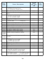
Value
Func.
Code
Name / Description
A_41
Torque boost method selection
• 00 Manual torque boost
• 01 Automatic torque boost
Default
Value
–FE / –FU /
–FR
00
A_42
Manual torque boost value
A_43
Manual torque boost frequency adjustment
11
A_44
V/f characteristic curve selection
• 00 V/f constant torque
• 01 V/f variable torque
00
A_45
V/f gain setting
100
A_51
DC braking enable
• 00 Disable
10.0
00
• 01 Enable
A_52
DC braking frequency setting
0.5
A_53
DC braking wait time
0.0
A_54
DC braking force during deceleration
A_55
DC braking time for deceleration
0.0
A_61
Frequency upper limit setting
0.0
A_62
Frequency lower limit setting
0.0
A_63
A_65
A_67
Jump (center) frequency setting
0.0
A_64
A_66
A_68
Jump (hysteresis) frequency width
setting
0.5
A_71
PID Enable
• 00 PID operation OFF
• 01 PID operation ON
00
A_72
PID proportional gain
1.0
A_73
PID integral time constant
1.0
A_74
PID derivative time constant
0.0
A_75
PV scale conversion
1.00
A_76
PV source setting
• 00 [OI] terminal (current input)
• 01 [O] terminal (voltage input)
A_81
AVR function select
• 00 AVR enabled
• 01 AVR disabled
• 02 AVR enabled except during decel
16
0
00
02 / 00 / 02
Set
Value
Func.
Code
Name / Description
Default
Value
–FE / –FU /
–FR
A_82
AVR voltage select
A_92
Acceleration (2) time setting
15.0
A_93
Deceleration (2) time setting
15.0
A_94
Select method to switch to Acc2/Dec2
profile
• 00 2CH input from terminal
• 01 transition frequency
00
A_95
Acc1 to Acc2 frequency transition point
0.0
A_96
Dec1 to Dec2 frequency transition point
0.0
A_97
Acceleration curve selection
• 00 Linear
• 01 S-curve
00
A_98
Deceleration curve selection
• 00 Linear
• 01 S-curve
00
Set
Value
230/230/200
400/460/400
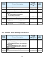
“B” Group: Fine-tuning Functions
Func.
Code
Name / Description
Default
Value
–FE / –FU /
–FR
B_01
Selection of automatic restart mode
• 00 Alarm output after trip, automatic
restart disabled
• 01 Restart at 0Hz
• 02 Resume operation after frequency
matching
• 03 Resume previous freq. after freq.
matching, then decelerate to stop and
display trip info
00
B_02
Allowable under-voltage power failure
time
1.0
B_03
Retry wait time before motor restart
1.0
17
Set
Value
Func.
Code
Name / Description
Default
Value
–FE / –FU /
–FR
B_12
Level of electronic thermal setting
Rated
current of
each inverter
B_13
Electronic thermal characteristic
• 00 Reduced torque • 01 Const. torque
01 / 01 / 00
B_21
Overload restriction operation mode
• 00 Disabled
• 01 Enabled for accel and constant
speed
• 02 Enabled for constant speed only
B_22
Overload restriction setting
01
Rated
current
x 1.25
B_23
Deceleration rate at overload restriction
1.0
B_31
Software lock mode selection
• 00 Low-level access, [SFT] blocks
edits
• 01 Low-level access, [SFT] blocks
edits (except F_01 and Multi-speed
parameters)
• 02 No access to edits
• 03 No access to edits except F_01 and
Multi-speed parameters
01
B_32
Reactive current setting
Note: For Japanese (–FR) versions, only
–055LFR, –055HFR, –075LFR, and
–075HFR models support this function.
58% rated
current
B_81
[FM] terminal analog meter adjustment
80
B_82
Start frequency adjustment
0.5
B_83
Carrier frequency setting
B_84
Initialization mode (parameters or trip
history)
• 00 Trip history clear
• 01 Parameter initialization
B_85
Country code for initialization
• 00 Japan version • 01 Europe
version
• 02 US version
01 / 02 / 00
B_86
Frequency scaling conversion factor
1.0
B_87
STOP key enable
• 00 Enable
00
5.0 / 5.0 /
12.0
• 01 Disable
18
00
Set
Value
Func.
Code
Name / Description
Default
Value
–FE / –FU /
–FR
B_88
Restart mode after FRS
• 00 Restart from 0Hz
• 01 Restart from frequency detected
from actual speed of motor
00
B_89
Data select for digital operator OPE-J
• 01 Output frequency (D_01)
• 02 Output current (D_02)
• 03 Motor direction (D_03)
• 04 PID PV feedback (D_04)
• 05 Input states for input terminals
(D_05)
• 06 Output states for output terminals
(D_06)
• 07 Scaled output frequency (D_07)
01
Set
Value
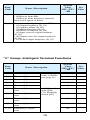
“C” Group: Intelligent Terminal Functions
Func.
Code
Name / Description
Fifteen option
codes available
(see page 21)
Default
Value
–FE / –FU /
–FR
C_01
Terminal [1] function
C_02
Terminal [2] function
00
C_03
Terminal [3] function
02 / 16 / 02
C_04
Terminal [4] function
03 / 13 / 03
C_05
Terminal [5] function
C_11
Terminal [1] active
state
C_12
Terminal [2] active
state
C_13
Terminal [3] active
state
00
C_14
Terminal [4] active
state
00 / 01 / 00
C_15
Terminal [5] active
state
00
01
18
• 00 Normally
open [NO]
• 01 Normally
closed [NC]
19
00
00
Set
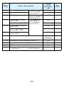
Value
Func.
Code
Name / Description
C_21
Terminal [11] function
C_22
Terminal [12] function
C_23
[FM] signal selection
Three option
codes available
(see page 22)
00
C_31
Terminal [11] active
state (–FU)
• 00 Normally
open (NO)
• 01 Normally
closed (NC)
— / 00 / —
Reserved (–FE / –FR)
C_32
Six option
codes available
(see page 22)
Default
Value
–FE / –FU /
–FR
01
00
00 / — / 00
Terminal [12] active
state (–FU)
— / 00 / —
Terminal [11] active
state (–FE / –FR)
00 / — / 00
C_33
Alarm relay terminal
active state
01
C_41
Overload level setting
Rated
current of
each inverter
C_42
Frequency arrival setting for accel
0.0
C_43
Arrival frequency setting for decel
0.0
C_44
PID deviation level setting
3.0
C_91
Debug mode enable
• 00 Display
• 01 No display
00
20
Set
Value
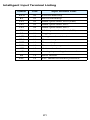
Intelligent Input Terminal Listing
Symbol
Code
FWD
00
Forward Run/Stop
Input Terminal Name
RV
01
Reverse Run/Stop
CF1
02
Multi-speed select, Bit 0 (LSB)
CF2
03
Multi-speed select, Bit 1
CF3
04
Multi-speed select, Bit 2
CF4
05
Multi-speed select, Bit 3 (LSB)
JG
06
Jogging
2CH
09
2-stage accel and decel
FRS
11
Free-run stop
EXT
12
External trip
USP
13
Unattended start protection
SFT
15
Software lock
AT
16
Analog input voltage/current sel.
RS
18
Reset inverter
PTC
19
PTC thermistor thermal protection
21
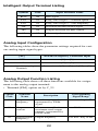
Intelligent Output Terminal Listing
Symbol
Code
RUN
00
Run signal
Input Terminal Name
FA1
01
Freq. arrival type 1 – constant speed
FA2
02
Freq. arrival type 2 – over-frequency
OL
03
Overload advance notice signal
OD
04
Output deviation for PID control
AL
05
Alarm signal
Analog Input Configuration
The following tables show the parameter settings required for various analog input signal types.
[AT]
External Frequency Command Input
OFF
[O] — [L]
ON
[OI] — [L]
(not assigned to any input
terminal)
Summation of [O] — [L] and [OI] — [L]
Analog Output Function Listing
The following table shows all three functions available for assignment to the analog output terminal:
• Terminal [FM], option set by C_23
Option
Code
Function
Name
Description
Corresponding
Signal Range
00
Output
frequency
Actual motor speed,
represented by PWM
signal
0 to max. freq. in Hz
01
Output
current
Motor current (% of
maximum rated output
current), represented by
PWM signal
0 to 200%
02
Digital output
frequency
Output frequency
0 to max. freq. in Hz
22
Notes:
23