1
DELI
C A S E S
MODEL:
OSAA
INSTALLATION & OPERATION
HANDBOOK
P061773M
9/03
Welcome to the ORIGIN2 display case family. We’re very pleased you
joined us.
This installation and operation handbook has been especially
prepared for everyone involved with ORIGIN2 display cases – owners,
managers, installers and maintenance personnel.
You’ll find this book different than traditional manuals. The most
dramatic difference is the use of many more illustrated instructions to
make it easier to read and to help you get the most from this innovative
new design. When you follow the instructions you should expect
remarkable performance, attractive fits and finish, and long case life.
We are interested in your suggestions for improvement both in case
design and in this handbook. Please call/write to:
Hill PHOENIX
Marketing Services Department
1925 Ruffin Mill Rd.
Colonial Heights, VA 23834
Tel: 804-526-4455
Fax: 804-526-7450
or visit our web site at
www.hillphoenix.com
We wish you the very best in outstanding food merchandising and a
long trouble-free operation.
TABLE OF CONTENTS
GENERAL INFORMATION – PAGES 2 - 4
General information, first step recommendations and case dimensional drawings.
THE USE OF CASTERS – PAGE 5
Cases roll on casters–general use and castor removal.
LINE-UP – PAGES 6 - 7
A ten step procedure for initial case lineup with illustrations.
TRIM-OUT – PAGES 8 - 9
A sixteen step procedure for trimming out cases with illustrations.
REFRIGERATION PIPING - PAGE 10
Diagram showing the refrigeration components of the self-contained deli case.
COMPONENT DEFINITIONS - PAGE 11
Operational descriptions of the refrigeration components.
PLUMBING – PAGE 12
Information on drain connections.
ELECTRICAL HOOKUP, WIRING DIAGRAMS, AND CONTROL SETTINGS - PAGES 13-16
Complete information on electrical connections.
CASE OPERATION – PAGE 17
Recommended settings for all case controls.
DEFROST AND TEMPERATURE CONTROL – PAGE 18
Defrost data. Sensor bulb locations.
AIR FLOW AND PRODUCT LOADING – PAGE 19
Air flow and load limits.
USE AND MAINTENANCE – PAGES 20 - 21
Cleaning and fan information.
PARTS ORDERING – PAGES 22 - 24
Replacement parts identification.
NOTES - PAGES 25 - 26
PRODUCT WARRANTY - Inside Back Cover
1
GENERAL INFORMATION
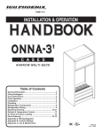
DESCRIPTION OF CASES: The refrigerated display cases described in this handbook
are part of the Hill PHOENIX, Origin2 design series. Specifically covered in this manual is
model OSAA, self-contained service deli case.
STORE CONDITIONS: Hill PHOENIX cases are designed to operate in an air conditioned
store with a system that can maintain 75OF (24OC) store temperature and 55 percent (maximum) relative humidity (CRMA conditions). Case operation will be adversely affected by
exposure to excessively high ambient temperatures and/or humidity.
REFRIGERATION SYSTEM OPERATION: Air cooled condensing units require ventilation for
efficient performance of condensers. Machine room temperatures must be a minimum of
65OF in winter and a maximum of 95OF in summer. Minimum condensing temperatures
should be no less than 70OF.
RECEIVING CASES: Examine fixtures carefully for shipping damage and shortages. For
information on shortages contact the Service Parts Department at 1-800-283-1109.
APPARENT DAMAGE: A claim for obvious damage must be noted on the freight bill or
express receipt and signed by the carriers agent, otherwise the carrier may refuse the claim.
CONCEALED DAMAGE: If damage is not apparent until after the equipment is unpacked,
retain all packing materials and submit a written request to the carrier for inspection within
15 days of receipt of equipment.
LOST ITEMS: This equipment has been carefully inspected to insure the highest level of
quality. Any claim for lost items must be made to Hill PHOENIX within 48 hours of receipt
of equipment.
TECHNICAL SUPPORT: If any technical questions arise regarding a refrigerated display
case contact our Customer Service Department in Richmond at 1-804-526-4455. For any
questions regarding our refrigeration systems or electrical distribution centers contact our
Customer Service Department in Conyers at 1-770-285-3200.
CONTACTING FACTORY: Should you need to contact Hill PHOENIX regarding a specific
fixture, be sure to know the case model number and serial number. This information is on
the serial plate located on the rear panel of the case (see next page for details). Ask for a
Service Parts Representative at 1-804-526-4455.
2
10 5/16 in
[26.1 cm]
REAR SLIDING DOORS
21 1/2 in
[54.6 cm]
FLAT REAR SILL
(OPTIONAL)
AMP PLATE &
SERIAL PLATE
LOCATION
54 15/16 in
[139.5 cm]
30 1/2 in
[77.5 cm]
32 3/16 in [81.8 cm]
33 1/4 in
[84.5 cm]
PLENUM
27 1/4 in
[69.2 cm]
COIL
22 1/2 in
[57.2 cm]
11 1/2 in
[29.2 cm]
28 3/8 in [72.0 cm]*
1 3/16 in [3.0 cm]
5 13/16 in [14.7 cm]
35 11/16 in [90.7 cm]
MODEL
OSAA-6’
38 5/16 in [97.3 cm]
49 1/16 in [124.6 cm]
DRAIN PAN
(optional)
CONDENSING UNIT
5 13/16 in [14.7 cm]
34 1/2 in
[87.6 cm]
21 1/2 in
[54.6 cm]
**
34 9/16 in
[87.7 cm]
38 5/16 in
[97.3 cm]
ELECTRICAL
49 1/16 in
[124.6 cm]
JUNCTION BOX
(STANDARD)
1 1/2 in [3.8 cm]
{END}
25 9/16 in [64.9 cm]
28 1/16 in [71.2 cm]
1 1/2" PVC DRAIN
CONNECTION
CL
FRONT OF CASE
72 in [182.9 cm] {6' case}
NOTES:
* STUB-UP AREA
** RECOMMENDED STUB-UP CENTERLINE FOR ELECTRICAL AND HUB DRAINS
l ENDS ADD APPROXIMATELY 1 INCH TO CASE HEIGHT
l AVAILABLE SHELF SIZES: 10" & 12"
3
GENERAL INFORMATION
4"
31 11/16"
BASEHORSE
LOCATIONS FOR
MODEL
OSAA
6' CASE
71 1/4"
FRONT OF CASE
4
CASES
MOVE ON
CASTERS
FOR EASIER INSTALLATION
ORIGIN2 cases are manufactured and shipped to
stores with casters installed on the base frame to
make the job of moving cases easier for everyone
involved with the manufacturing, shipping and installation process.
Casters not only speed up the process, but they also
reduce the chance of damage from raising and lowering cases with ”J” bar to place them on dollies,
skates or rollers. In most situations, one or two persons can move the case with ease.
1
ROLL TO LINEUP POSITION. Casters may remain in
place to move the cases to staging areas around the
store, prior to final installation. When ready for final
line-up, roll the case to set position, then remove
casters.
3
CASTERS MAY BE DISCARDED.
2
ROLL OUT OF TRUCK. When there is a truck - level
delivery dock, cases may be rolled directly from the
truck to the store floor. [CAUTION] If skid boards are
required to unload cases, casters should be removed
prior to sliding them down the skid; after which they
can be reinstalled on case.
4
REMOVE COTTER PIN. Removing the casters is
easy. Simply flatten and hammer out cotter pins
then lift the case with “J” bar, and the casters will
fall off.
[CAUTION] Make certain hands are out of the way.
5
LINE UP
BASE RAIL
Consult With General Contractor
1
Snap Chalk Lines
2
Ask the general contractor if there
have been changes in the building
dimensions since the print you are
using was issued. Also, ask the
points of reference from which you
should take dimensions to locate the
cases.
Mark floor where cases are to be
located for the entire lineup.
Level Floor. Use Laser Transit
Set Shims On Basehorse Locations
4
Leveling is necessary to assure proper case alignment. Locate highest
point on chalk line as reference for
determining height of shim-pack
levelers. A laser transit is recommended for precision and requires
just one person.
5
Locate basehorse positions along
chalk lines. Spot shim packs at each
basehorse location.
6
BASE RAIL
Snap Lines On Base Rail
Locations
Snap lines where base rails are positioned, not the front or back edges of
the cases. See case cross section
drawing, pages 3-4 for rail location
dimensions.
3
Position First Case In Lineup,
Remove Casters, Level
Roll first case into position. Raise
case from end under cross support
using “J” bar. Remove cotter pins and
casters. [CAUTION! Keep hands from
under case] Level case on shims.
6
CAULK
Position Next Case In Line Up
7
Roll case approximately 2’ from
adjoining case. Remove casters on
the end nearest to the next case.
Allow casters to remain on opposite
end to assist in pushing cases together - then remove them.
Remove Shipping Accessories
From Case. Add Sealant.
Remove anything from case that may
interfere with case joining (eg. shipping braces). Run a bead of sealant
around entire end before pushing
cases tightly together.
8
Loosen Bumper And Cornice
9
Loosen screws on master bumper.
Move bumper joint to a position for
sliding between adjoining case
bumper.
5
4
1
3
2
Bolt Cases Together Using Bolt
Holes Provided
10
Push cases tightly together. Bolt
cases together through the five holes
provided in the “C” frame and pipe
chase as shown in illustration.
Tighten until all margins are equal; do
not over tighten.
Ask about our case installation video available by request through your local Hill PHOENIX Sales or Field Service
Representative. Spanish version available.
7
TRIM OUT
Now that cases have been
positioned and leveled, you
may proceed to trim-out
case lineup. Trim parts have
been designed to be applied
easily with only a small
number of fasteners
required. Most external
parts are adjustable to
achieve almost invisible,
snug-fitting joints and a
high level of excellence in
fit and finish.
3
Slide bumper joint to the center of the
joint between the two cases. Use screw
driver in hole provided.
Tighten all joint bolts. Draw up tightly,
but do not over tighten.
1
Adjust polymer master bumper joints, if
required. First loosen bumper screws.
4
Close seam where bumper joins case
end. Bumper joint closes seam that
may develop if master bumper is moved
away from end to close case-to-case
joint seam.
Slide master bumper left or right to
close seam as required. Bumper joint
neatly finishes any gap that may remain.
ACRYLIC
TAPE
2
5
LOWER
REAR
BAFFLE
PLENUM
COVER
DECK PAN
PLENUM
COIL
PIPE
CHASE
6
Seal joints along pipe chase seam with
the caulk provided.
7
Apply acrylic tape over pipe chase seam.
Tape is found with the ship loose items
and acts as a watershed preventing
water from settling in case joint.
8
8
Install plenum covers under deck pans.
The plenum covers are shipped loose in
the case and are installed between the
lower rear baffle and the fan plenum.
CURVED FRONT
PANEL
CURVED FRONT
PANEL JOINT
9
Close joints of front panel. The panel is
slotted on the bottom to allow left or
right adjustment as required.
TOP SILL
JOINT
10 11
Install curved front panel joint (if cases
come equipped with curved front panels). Curved panel joints are shipped
loose in the case and are attached with
the screws provided. Wide joints (1”)
are for case-to-case joining and narrow
joints (1/2”) are for cases with ends.
Attach lower front panel (for cases on
11” baseframes). Slots and tabs are
designed for easy installation without
fasteners. The lower front panel is slotted to allow adjustment left or right as
required.
TOP SILL
REAR SILL
GLASS
PRESSURE
BAR
REAR SILL
JOINT
MULLION
12 13 14
Install top sill joint. The top sill joints are
shipped loose in the case. The front lip
of the joint fits into the crevice between
the top sill and the glass pressure bar.
The rear lip is attached to the back of
the case with the screws provided.
Install rear sill joint. The rear sill joints
are shipped loose in the case. The bottom portion of the joint should be slid on
the rear sill first then the top lip fits
between the rear sill and the mullion.
Secure the joint underneath the rear sill
with the screws provided.
15 16
Insert kickplate into “J” rail. Slide the
kickplate up and behind the lower front
panel bracket then down on the “J” rail.
Insert nose bumper into master bumper
channel. Roll nose bumper into channel
along entire lineup (up to 96’). We recommend that the nose bumper be left in
the store 24 hours before installing. DO
NOT STRETCH the bumper during
installation as it will shrink to its original
length and leave a gap.
9
Install the “J” rail onto the case base
rail. For cases with an 11” baseframe,
the “J” rail easily slides over the base
rail and requires no fasteners. Space
“J” rails evenly along the base rail (2 “J”
rails per 6’, 8’, and 12’ case). For cases
with the 7” baseframe there is a single
“J” rail that is screwed into place.
NOTE: An easy technique for one
person is to press against nose
bumper with leg as you guide
bumper into channel with a screen
spline. Insert bottom first.
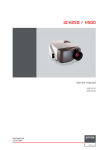
REFRIGERATION
COMPONENTS
Refrigeration components for the
OSAA-6’ are easily accessible in the tank and
underneath the case. The expansion valve
and suction line 1/4” access valve are both
located in the left hand front side of the tank
and are accessible without lifting the fan
plenum. These components may be reached
by lifting only the left hand deck pan which
minimizes the need to remove product.
The diagram below illustrates all of the
refrigeration components in the OSAA-6’ case.
The components surrounded by the box are
located within the case tank. Basic definitions of
these components are listed on the following
page.
Evaporator
Tank
Area
TXV
Bulb
1/4”
Access
Valve
Fan
Plenum
TXV
Flow Direction
Suction Line
Solenoid
Flow Direction
Accumulator
Dual Pressure
Control
Filter
Drier
Condenser
Service
Valve
Service
Valve
Compressor
Receiver
Condenser
Fan
High Pressure
Warning Light
COMPONENT DEFINITIONS
Access Valve - Access port on the evaporator that allows service personnel to check system pressure.
Accumulator - A device installed on the suction line that is used to boil off small amounts of liquid refrigerant so liquid does not reach the compressor.
Compressor - An electrically driven piston pump that pumps vapor refrigerant from a low pressure level
to a higher pressure level.
Condenser - The component in a refrigeration system that transfers the heat that was absorbed by the
refrigerant in the evaporator and the heat of compression from the system by condensing the refrigerant.
Condenser Fan - Fan that forces air through the air cooled condenser to aid heat transfer.
Dual Pressure Control - A device that protects the compressor from low charge and high pressure.
Evaporator - The component of the refrigeration system that absorbs heat from the air by boiling liquid
refrigerant to vapor.
Evaporator Fans - Fans that circulate air through the case and force air through the evaporator to aid heat
transfer.
Filter Drier - A device installed on the liquid line of a refrigeration system that removes water and other
impurities from the refrigerant in the lines during initial start-up.
High Pressure Warning Light - Indicator light that warns the operator that the system pressure is to high.
Receiver - The component in a refrigeration system that stores liquid refrigerant that is not being used by
the system in low load conditions or when the system is shut down.
Service Valve - A manually operated valve in the refrigeration system that is used for various service operations such as isolating the high or low sides of the system.
Suction Line Solenoid - A device that prevents liquid from entering the compressor.
Thermostatic Expansion Valve (TXV) - A valve that controls the flow of liquid refrigerant to the evaporator coil and also separates the high pressure side of the system from low pressure side of the system.
Thermostatic Expansion Valve (TXV) Bulb - A bulb that is attached to the suction line of the evaporator that controls the TXV. Inside the bulb is a charge that reacts to temperature and regulates the flow of
refrigerant through the expansion valve.
11
PLUMBING
The kickplate is shipped loose with the
case for field installation, therefore you
should have open access to the drain line
area.
The drain outlet is located front and
center of the cases for convenient access
and is specially molded out of ABS material.
The “P” trap, furnished with the case, is
constructed of schedule 40 PVC pipe. Care
should be given to assure that all connections are water tight and sealed with the
appropriate PVC or ABS cement.
If the kickplate has been installed, you
will find it very easy to remove. See instructions below, or the trim out section of this
manual on page 9.
The drain lines can be run left or right
of the tee with the proper pitch to satisfy
local drainage requirements. The drain can
be piped to a evaporative drain pan at the
owners option.
DRAIN PAN
(optional)
5 13/16 in [14.7 cm]
34 1/2 in
[87.6 cm]
21 1/2 in
[54.6 cm]
**
34 9/16 in
[87.7 cm]
38 5/16 in
[97.3 cm]
49 1/16 in
[124.6 cm]
1 1/2 in [3.8 cm]
{END}
1 1/2" PVC DRAIN
CONNECTION
CL
FRONT OF CASE
72 in [182.9 cm] {6' case}
NOTES:
** RECOMMENDED STUB-UP CENTERLINE FOR ELECTRICAL AND HUB DRAINS
MODEL OSAA
HOW TO REMOVE KICKPLATE
LIFT UP FROM “J”
RAIL AND PULL OUT
KICKPLATE
“J” RAIL
12
ELECTRICAL HOOKUP
Electrical hookups for the OSAA are made
to a junction box located underneath the case on
the bottom left hand front. The light ballasts for
the case are located under the rear sill behind a
removable access cover as shown below.
For case-to-case wiring, run “greenfield”, or other conduit, between junction
boxes. When connecting to the junction box
field connections should be made on the
right hand side of the box to allow more room
inside for wire connecting.
5 13/16 in [14.7 cm]
34 1/2 in
[87.6 cm]
21 1/2 in
[54.6 cm]
**
38 5/16 in
[97.3 cm]
ELECTRICAL
49 1/16 in
[124.6 cm]
JUNCTION BOX
(STANDARD)
BALLAST
LOCATION
1 1/2 in [3.8 cm]
{END}
REAR SILL
25 9/16 in [64.9 cm]
REMOVABLE
COVER
28 1/16 in [71.2 cm]
CL
BALLAST
LOCATION
FRONT OF CASE
72 in [182.9 cm] {6' case}
NOTES:
** RECOMMENDED STUB-UP CENTERLINE FOR ELECTRICAL AND HUB DRAINS
MODEL OSAA-6’
WIRING NUMBERS AND COLORS
COMPONENT
WIRE NUMBER
COLOR CODING
EVAPORATOR FANS, 120 VOLT
3
WHITE
4
BLACK
LIGHTS, 120 VOLT
11
WHITE
12
BLACK
13
WHITE
14
BLACK
19
YELLOW
20
YELLOW
DEFROST TERMINATION CONTROL, 120 VOLT
21
PURPLE
23
ORANGE
DEFROST HEATERS, 208/240 VOLTS
L1
RED
ANTI-CONDENSATE HEATERS, 120 VOLT
TEMPERATURE CONTROL, 120 VOLT
EQUIPMENT GROUNDING CONDUCTOR
L2
BLUE
-
GREEN
13
CONTROL SETTINGSFan
Status
LED
MODEL
OSAA-6’
Defrost Compressor
Status
Status
LED
LED
Manual Defrost
Button
Up
Button
Enter
Button
Down
Button
Factory Control Settings
Parameter
HY
LL
HL
CC
Co
AH
AL
Ad
At
dF
dE
dt
di
dd
dC
dU
dP
dr
iF
id
FF
Fd
Fr
SF
So
Un
PU
Description
Setpoint
Hysteresis (differential) [1 to 9oF/oC]
Setpoint Low Limit [67oF (55oC) to HL]
Setpoint High Limit
[LL to 99oF/oC]
Anti-Short Cycling Timer [0 to 9 min.]
Deep Freeze Cycle Time [0 to 99 min.]
High Temperature Alarm Value (degrees above setpoint) [0 to 55oF/oC]
Low Temperature Alarm Value (degrees below setpoint) [-50 to 0oF/oC]
Alarm Differential [1 to 9oF/oC]
Alarm Time Delay [0 to 99 min.]
Defrost Type (0-electrical; 1-hot gas)
Defrost End Mode (0-timed defrost; 1-temperature terminated defrost)
Defrost Termination Temperature [32oF to 68oF (0oC to 20oC)]
Defrost Interval [0 to 99 hours]
Maximum Defrost Duration [1 to 99 min.]
Dripping Time After Defrost [0 to 99 min.]
Initial Defrost Interval (time before first defrost after startup) [0 to 99 min.]
Defrost Display (0-displays last value before defrost; 1-displays setpoint)
Display Delay After Defrost [1 to 99 min.
Digital Input Type (0-no digital input;
1-if digital input open, compres. off w/alarm on:
2-if digital input open, alarm on (contacts closed);
3-if digital input open, fan off w/alarm on)
Digital Input Time Delay [0 to 99 sec.]
Fan Function (0-fan runs parallel with compressor; 1-fan on)
Fan Start-Up Delay (after defrost) [0 to 99 min.]
Fan Start-Up Temp. [-22oF to 41oF/-30oC to 5oC]
Sensor Failure Operation (0-compressor off; 1-compressor on;
2-compressor on/off based on last 4 cycles)
Temperature Sensor Offset [-20o to 20oF/oC]
Units Used (0-oC; 1-oF)
Display Refresh Rate [1 to 99 sec.]
14
Factory Settings
OSAA-6’
22
3
18
30
1
60
10
-10
5
3
0
1
50
8
45
0
0
0
5
0
0
1
0
40
1
0
1
1
Error Code
F1 Indicates an open or
shorted temperature
sensor. Cycle Power
to reset control.
F2 Indicates an open or
shorted evaporator
sensor. Correct
problem to reset
control.
A1 Digital input was open
for longer than time
delay (id) and digital
input option (if) 1 is
selected.
A2 Digital input is closed
System Status
To program parameters:
1. Hold the “Enter” button down for
about 10 seconds. The display will
change to “Hy.”
Alarm output on compressor
runs according to the sensor
failure mode selected (parameter sf)
2. Press the “Up” and “Down” button
until the desired parameter is shown
Alarm output on defrost
cycle is controlled by parameters di (defrost initiation)
and dd (defrost duration)
3. Press the “Enter” button. The parameter’s current value will be shown.
4. Press the “Up” and “Down” button
until the desired value is shown.
Compressor off
Alarm output on
5. Press the “Enter” button to save the
new value. After 10 seconds of inactivity, the display will return to its normal
function.
To change setpoint:
Alarm output is on
and digital input option
(if) 1 is selected.
A3 Digital input is open
for longer than time
delay (id) and digital
input option (if) 3 is
selected.
1. Hold down the “Enter” button down
for 3 seconds. The display will change
to show the setpoint.
Fan output is off
Alarm output is on
2. Press the “Up” or “Down” button until
you reach the new setpoint.
3. Press the “Enter” button to save the
new setpoint.
HI
Temperature has
exceeded the high
temp. alarm value (AH).
LO Temperature has fallen
Alarm output is on
To lock and unlock the unit:
}
Alarm output is on
below the low temp.
alarm value (AL).
To Initiate a deep freeze cycle:
EE Program failure: control Alarm output is on
must be replaced.
Press the “Enter,” the “Up,” and the
“Down” buttons in sequence and hold
them all down until “- - -” is displayed.
Hold for about 10 seconds until the
current temperature is displayed.
Other outputs off
}
Press and the “Enter” and “Up” buttons
in sequence and hold for five seconds.
The compressor status LED will light.
To Initiate Self-Test:
To Initiate Manual Defrost:
Hold the Defrost button down for 3
seconds.
}
15
IMPORTANT: Disconnect loads before
beginning self test. Cycle power to
resume operation.
Press the “Up” and the “Down” buttons
in sequence and hold for 5 seconds.
1
BLK
5
J4
S1
SC
S2
CP1
DH1
FNO
CP2
DH2
L2
120
120VacN
J6
6
48
42
CONNECT CONDENSING
1
HOT
J5
J5-Amb temp
J5-Common
J5-Def temp
J6-120V Hot
Common
J6-Fan
J6-Compressor
J6-Defrost
BLK
BLK
BLK
33
15
16
CPC-ESC3
CONVERSION
4
13
11
HOT
TERMINAL
BLOCKS
14
32
50
12
2
48
WIRING
HOLE
57
33
AC PLUG
32
FNC
48
CP1
120
240
BLK
CP2
DH1
49
50
DH2
V1
V2
2
47
BLUE
48
39
38
BLUE
D
S2
BACK OF CONTROL MODULE
DEFROST PROBE (LOCATION- COIL)
47
48
WHITE
12
11
GREEN
WHITE
BLACK
WHITE
BLACK
23
21
52
51
CONDUIT
GRN
WHT
BLK
K
BL
WIRE
CAPS
(3)
GROUND
SCREW
PURPLE
13
20 14
19
CONDENSING UNIT J-BOX
TEMP
PROBE
DEFROST
PROBE
WIRES FROM PROBES
WIRES FROM POWER MODULE
GREEN
SC
S1
RED
WHITE
WHITE
RED
V1
V2
01
02
WHITE
RED
CONDENSING UNIT
GROUND
SCREW
SUCTION LINE
SOLENOID
VALVE COIL
HI
PRESSURE
SWITCH
WIRE
CAPS
CONTROL
MODULE
DRAIN
PAN
RECEPTACLE
TO CONTROL J-BOX
FNO
L2
ALM
CONTROL J-BOX
WIRING
HOLE
3
47
GRN
1
PROBES
CHASSIS
GROUND
HOT
JUMPER
(BLACK)
P061904A/P061905K
CPC
ESC3
42 42
42 42
49
J4-120Vac Hot In
J4-120Vac Neu In
53
58
57
54
4
NEUTRAL
120VacH
P055258H
Fan
JOHNSON CONTROL
MR4PMUHV
WIRE
CAP
58
53
Compressor
120V Hot
Common
Defrost
SW1
POWER
SWITCH
GROUND
TERMINAL
BLOCK
NEUTRAL
TERMINAL
BLOCKS
NEUTRAL
JUMPER
(WHITE)
BLK
Common
WIRE
CAPS
(2)
Def temp
GREEN
RED
BLK
PURPLE
SERVICE LIGHT
(HI PRESSURE)
Amb temp
WHITE
02
GROUND
01
BL
K
16
BLK
YELLOW
BLACK
SW1
BLACK
{
120V LIGHTS
RED
TO
COMP. ROOM {
L2
L1
RED
WHITE
{
YELLOW
TO
COMP. ROOM {
BLUE
{
GREEN
WHITE
BLUE
BLUE
J2-2
RED
BLU
BLU
3
4
BLACK
WHITE
BLU
BLU
RED
BLU
RED
BLU
BLU
BLU
J2-1
RED
WHT
BLK EB6
RED
RED
BLK EB6
WHT
YEL
YEL
WHTEB2
BLK
RED
WHT EB1
BLK
51
52
21
24
22
U
14
BL
12
11
YELLOW
YELLOW
TO CONTROL J-BOX
FANS
SHELF LIGHTS (OPTIONAL)
BLACK
DUAL PRESSURE SWITCH
ANTI-COND.
HEATERS
120V
OPT DEFROST
208/240V
{
120V FANS
REAR SILL
HTR1
L3
L1
HTR2
TEMP PROBE (LOCATION- RETURN AIR)
L2
FAN MOTOR
M1
INSIDE CASE
P3
DEFROST HEATERS (OPTIONAL)
J3
L8
WHITE
M2
FAN MOTOR
BLACK
L5
NOSE LIGHTS
PRIMARY CORNICE LIGHTING
FRONT GLASS ANTI-COND HEATER
TEMP. CONTROL (OPTIONAL)
DEF. TERM. CONTROL (OPTIONAL)
L7
L4
TWO ROW CORNICE LIGHTING (OPTIONAL)
(OPTIONAL)
L6
WIRING DIAGRAMSMODEL
OSAA-6’
CASE OPERATION
American Style Self-Contained Curved Glass Service Deli Merchandiser
OSAA - 6’
System Requirements
Model
OSAA
Volts
Hz
Wire
Minimum
Circuit
Ampacity
120
60
2 wire + ground
9.74
6’
Maximum
Fuse
Size
15
Electrical Data
Standard Fans
Model
Amps
Watts
3
1.02
51
6’
OSAA
120 Volts
Fans per
Case
0.53
Anti-Condensate
Heaters
Drain Pan
Heater
120 Volts
Condenser
Fan
120 Volts
Amps Watts
66
Defrost
Heaters
120 Volts
120 Volts
Amps
Watts
Amps
Watts
Amps
Watts
4.16
500
0.42
50
5.0
600
Guidelines & Control Settings
24 hr Energy Suction Pressure @ Superheat Set Point Discharge Air Return Air Discharge Air Velocity1
@ Bulb (oF)
(FPM)
Usage (kWh) Case Outlet (psig)
(oF)
(oF)
Model
20
OSAA-6’
1
30
6-8
39
235
Average discharge air velocity at peak of defrost.
Condensing Unit Data
Model
Volts
Phase
Frequency
(Hz)
HP
RLA2
(amps)
LRA3
(amps)
Refrig.
lbs of
Refrig.
OSAA-6’
115
1
60
1/3
7.45
37.5
R134A
2.5
2
RLA - Running Load Amps.
3
LRA - Locked Rotor Amps.
Defrost Controls
Electric Defrost
4
Timed Off Defrost
Hot Gas Defrost
Reverse Air Defrost
Model
Defrosts
Per Day
Fail-safe
(min)
Termination
Temp. (°F)
Fail-safe
(min)
Termination
Temp. (°F)
Fail-safe
(min)
Termination
Temp. (°F)
Fail-safe
(min)
Termination
Temp. (°F)
OSAA-6’
2
35
49
- - -4
---
---
---
---
---
NOTE: - - - not an option on this case model.
Medium Temperature Defrost Schedule
No. Per Day
1
2
3
4
Hours
12 midnight
12 am - 12 pm
6 am - 2 pm - 10 pm
12 - 6 am - 12 - 6 pm
All measurements are taken per CRMA specifications.
17
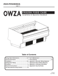
DEFROST AND TEMP CONTROL
It is important to consult the control
setting guidelines shown on page 17 before
setting defrost times. Further adjustment may
be required depending on store conditions.
These cases are equipped with Electric
Defrost. The sensor bulb and probe for electric
defrost termination and the sensor bulb for
temperature control are located behind the
front baffle at the location shown in diagram 1
below.
The defrost termination control thermostat and the temperature control thermostat
are located under the rear sill behind an easily
removable cover, as shown in diagram 2.
1
• Electric defrost termination control sensor bulb location
• Electric defrost termination probe location
• Temperature control sensor bulb location (OSA)
Rear Sill
Thermostat
Location
Ballast
Cover
18
2
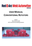
AIR FLOW AND PRODUCT LOADING
Cases have been designed to provide maximum product capacity within the refrigerated
air envelope. It is important that you do not
overload the food product display so that it
impinges on the air flow pattern.
Overloading will cause malfunction and the
loss of proper temperature levels, particularly when discharge and return air sections are
covered. Please keep products within the
load limit lines shown on the diagram.
DISCHARGE..............1
LOAD LIMIT...............2
3
2
AIR FLOW..................3
RETURN AIR GRILL...4
4
1
MODEL
OSAA
19
USE AND MAINTENANCE
CASE CLEANING
The coil is covered to keep food fluids from entering, but
the cover lifts up easily when coil cleaning is desired. The
fan plenum also lifts up for cleaning, exposing a major
portion of the inside bottom of the tank. Make certain the
coil cover is properly closed after cleaning to avoid air
leaks. Front return air grills snap out for cleaning; no fasteners are used.
Case is designed to facilitate cleaning. There is a wide
radius formed on the front and back of the inside bottom
that helps accelerate liquid flow and eliminates difficult-toclean sharp corners. All surfaces pitch to a deep-drawn
drain trough that angles toward the front and center of case
where the waste outlet is located for easy access.
DISCHARGE AIR GRILL
(Remove for Cleaning)
COIL
COVER
PLENUM
FRONT BAFFLE
(Pull Forward)
COIL
POSITIVE DRAIN OFF
COIL COVER AND PLENUM LIFT UP
CLEAN DISCHARGE AIR GRILL
CLEANING PROCEDURES
• A periodic cleaning schedule should be established to maintain proper sanitation, insure maximum operating efficiency, and
avoid the corrosive action of food fluids on metal parts that are left on for long periods of time. We recommend cleaning once
a week.
• To avoid shock hazard, be sure all electrical power is turned off before cleaning. In some installations, more than one
disconnect switch may have to be turned off to completely de-energize the case.
• Check waste outlet to insure it is not clogged before starting the cleaning process and avoid introducing water faster than the
case drain can carry it away.
• Avoid spraying cleaning solutions directly on fans or electrical connections.
• Avoid using high pressure water to flush the tank. A hose without a nozzle should provide enough pressure for cleaning
purposes. Always use cold water.
• Allow cases to be turned off long enough to clean any frost or ice from coil and flue areas.
• Remove and clean discharge honeycomb. You may need to use spray detergent and a soft, long bristle brush.
• Use mild detergent and warm water. When necessary, water and baking soda solution will help remove case odors. Avoid
abrasive scouring powders or pads.
• When cleaning non-glare glass be sure to use a standard glass cleaner and not a multi-purpose cleanser or combination
cleanser.
• A mixture of white vinegar and water or isopropyl alcohol straight from the bottle is very effective in cleaning “build-up” on
non-glare glass.
• Under no circumstances should abrasive cleaning solutions such as scouring powders or steel wool be used to clean nonglare glass.
• When cleaning rear door tracks be sure to remove the rear doors and clean from the outside channel to the inside channel
using the wipe-out groove machined into the track.
• Remove front panels and clean underneath the case with a broom and a long handled mop. Instructions for removing the
front panels can be found on page 9 of this manual.
• Use warm water and a disinfecting cleaning solution when cleaning underneath the cases.
20
FANS
2
The evaporator fans are equipped with 5 watt
fan motors, 1550 RPM’s. The motor has a counter
clockwise rotation when viewed from the shaft end.
The fan blades are 6” in diameter and the blades are
pitched according to the charts below. It is important that the blade pitch be maintained as specified. Do not attempt a field modification by
altering the blades.
Fan motors may be changed with an easy
two-step process without lifting up the plenum,
thereby avoiding the necessity to unload the entire
product display to make a change:
1. Unplug the fan motor, easily accessible out
side the plenum
1
2. Remove three fasteners, then lift out the
entire fan basket
Model OSAA
6’
MODEL
OSAA-6’
21
No.
Fans
Blade
Pitch
2
37
o
PARTS ORDERING
48
36
53
9a
20
46
56
55
21
28
29
5
9
22
82
87
88
81
2
17
26
3
42
1
66
24
11
E10
E09
77
69
E11
MODEL
OSAA
E01
23
49
E10
50
E09
E06
E20
E11
E07
22
Location
Number
1
2
3
5
9
9a
11
17
20
21
22
23
24
25
26
28
29
36
42
46
48
49
50
53
54
55
56
62
66
69
77
81
82
83
87
88
E01
E02
E03
E05
E06
E07
E08
E09
E10
E11
E19
E20
Part Descriptions
Kickplate, Storm Grey
Master Bumper, Featherstone, Smoke, White, French Vanilla, Black
Lower Front Panel, Painted or Stainless
Front Glass, Lift-Up Thermopane
Deck Pan, Painted, Unpainted, Stainless
Plenum Cover
Front Baffle, Aluminum, Painted White, Custom Color, or Stainless
Nose Bumper, Custom Color
Lower Rear Baffle, Painted White, Custom Color, or Stainless
Shelf Standard, Specify standard or Vieler Shelving
Shelves, Lighted or Unlighted, Painted White, Custom Color or Stainless
Electrical Junction Box, or Sliding Ballast Tray
“J” Rail, for Kickplate
Top Flue Panel, Painted Custom Color or Stainless (Not Shown)
Front Panel, Painted Custom Color, or Stainless
Discharge Air Grill
Lightrod,
Plug Button
Glass Pressure Bar
Glass Clamp
Rear Sill, Stainless Steel
Rear Filler Panel
Lamp Shield
Mullion Cover, Stainless Steel
Inside Mullion Cover, (Not Shown)
Doors, Specify Outside or Inside when ordering
Door Frame
Light Rod Cover (Not Shown)
Front Extensions, Inside and Outside
Coil, Specify upper or lower coil
P-Trap
Wire Racks
Tag Moulding
Thermometer, and Bracket (Not Shown)
End Assembly, Solid, Full view, Custom Color
Identify, Left or Right hand, Color of Panel, and color of PVC End Trim
End Kickplate, Storm Grey
Defrost Heaters
Anti-Condensate Heaters, (Not Shown)
Thermostats, Temperature and Defrost Termination Control, (Not Shown)
Light Switch, (Not Shown)
Lamp Holder
Bulb
Ballast, Electronic, (Not Shown), (Identify by brand name and model number)
Fan Motor - State High Efficiency or Standard
Fan Blade 6”
Fan Basket, 6”
Receptacle, Recessed, Shelf Light Outlet, White (Not Shown)
Fan Cord-Set - High Efficiency or Standard (Not Shown)
Note: Ballasts are located under the rear sill for cases equipped with a standard rear sill . Cases equipped with a flat
rear sill have the ballasts located in a sliding ballast tray underneath the case.
23
PARTS ORDERING
Procedure
1. Contact the Service Parts Department
Hill PHOENIX
1925 Ruffin Mill Road
Colonial Heights, Virginia 23834
Tel: 800-283-1109
Fax: 804-526-3897
2. Provide the following information about the part you are ordering:
• Model number and serial number of the case on which
the part is used.
• Length of part, if applicable, I.E. 6’.
• Color of part if painted, or color of polymer part.
• Whether part is for left hand or right hand application.
• Whether shelves are with or without lights.
• Quantity
*Serial plate is located on rear panel on the right hand side of
the case (See illustrations on page 3).
3. If parts are to be returned for credit, ask the Parts Department to
furnish you with a Return Materials Authorization Number.
24
NOTES
25
NOTES
26
WARRANTY
HEREINAFTER REFERRED TO AS MANUFACTURER
FOURTEEN MONTH WARRANTY. MANUFACTURER’S PRODUCT IS WARRANTED TO BE FREE FROM
DEFECTS IN MATERIAL AND WORKMANSHIP UNDER NORMAL USE AND MAINTENANCE FOR A
PERIOD OF FOURTEEN MONTHS FROM THE DATE OF ORIGINAL SHIPMENT. A NEW OR REBUILT
PART TO REPLACE ANY DEFECTIVE PART WILL BE PROVIDED WITHOUT CHARGE, PROVIDED THE
DEFECTIVE PART IS RETURNED TO MANUFACTURER. THE REPLACEMENT PART ASSUMES THE
UNUSED PORTION OF THE WARRANTY.
This warranty does not include labor or other costs incurred for repairing, removing, installing, shipping,
servicing, or handling of either defective parts or replacement parts.
The fourteen month warranty shall not apply:
1. To any unit or any part thereof which has been subject to accident, alteration, negligence, misuse or
abuse, operation on improper voltage, or which has not been operated in accordance with the
manufacturer’s recommendation, or if the serial number of the unit has been altered, defaced, or removed.
2. When the unit, or any part thereof, is damaged by fire, flood, or other act of God.
3. Outside the continental United States.
4. To labor cost for replacement of parts, or for freight, shipping expenses, sales tax or upgrading.
5. When the operation is impaired due to improper installation.
6. When installation and startup forms are not properly complete or returned within two weeks after startup.
THIS PLAN DOES NOT COVER CONSEQUENTIAL DAMAGES. Manufacturer shall not be liable under any
circumstances for any consequential damages, including loss of profit, additional labor cost, loss of
refrigerant or food products, or injury to personnel or property caused by defective material or parts or for
any delay in its performance hereunder due to causes beyond its control. The foregoing shall constitute
the sole and exclusive remedy of any purchases and the sole and exclusive liability of Manufacturer in
connection with this product.
The Warranties are Expressly in Lieu of All Other Warranties, Express of Implied and All Other
Obligations or Liabilities on Our Part. The Obligation to Repair or Replace Parts or Components
Judged to be Defective in Material or Workmanship States Our Entire Liability Whether Based on Tort,
Contract or Warranty. We Neither Assume Nor Authorize Any Other Person to Assume for Us Any
Other Liability in Connection with Our Product.
MAIL CLAIM TO:
Hill PHOENIX
Hill PHOENIX
Display Merchandisers
1925 Ruffin Mill Road
Colonial Heights, VA 23834
804-526-4455
Refrigeration Systems &
Electrical Distribution Products
709 Sigman Road
Conyers, GA 30013
770-285-3200
6/00
Warning
Maintenance & Case Care
When cleaning cases the following must be performed
PRIOR to cleaning:
To avoid electrical shock, be sure all electric power is
turned off before cleaning. In some installations, more
than one switch may have to be turned off to completely
de-energize the case.
Do not spray cleaning solution or water directly on fan
motors or any electrical connections.
All lighting receptacles must be dried off prior to insertion
and re-energizing the lighting circuit.
Please refer to the Use and Maintenance section of this installation manual.
804-526-4455
ASH3090
1925 Ruffin Mill Road, Colonial Heights, VA 23834
Due to our commitment to continuous improvement all specifications are subject to change without notice.
Hill PHOENIX is a Sustaining Member of the American Society of Quality.
CRMA endorsed
Visit our web site at www.hillphoenix.com