1
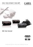
INSTALLATION & OPERATION
HANDBOOK
onna- 3'
C A S E S
NARROW MULTI-DECK
Table of Contents
General Information ........................................................... 2
Using Outriggers ................................................................ 3
Case Dimensions................................................................ 4
Case Operation ................................................................... 5
Installation........................................................................... 6
Plumbing ............................................................................. 7
Refrigeration Components ................................................ 8
Refrigeration Piping ........................................................... 9
Electrical Hook-Up....................................................... 10-11
Defrost & Temperature Control ....................................... 12
Air Flow & Product Loading ............................................ 13
Parts Ordering .............................................................14-15
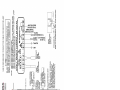
Appendix A: Wiring Diagrams
Appendix B: Control Settings
Appendix C: Use & Maintenance
P056623B
Rev. 2 09/08
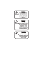
DANGER
Remove hands and feet
from beneath the case
before the casters are
removed. Failure to do
so may result in serious
injury when the case is
lowered.
DANGER
Once an outrigger have
been removed, DO NOT
push or attempt to move
the case until all remaining outriggers are removed. Doing so may
cause the case to tip over,
possibly resulting in serious injury or death.
DANGER
SHOCK HAZARD
Always disconnect power
to case when servicing
or cleaning. Failure to do
so may result in serious
injury or death.
GENERAL INFORMATION
Welcome to the Hill Phoenix display case family. We’re very pleased that you’ve chosen Hill PHOENIX for your food
merchandising needs.
This handbook is targeted to individuals involved in the installation and/or operation of Hill Phoenix display cases and
contains detailed illustrations and important information about the product. By closely following the manual’s instructions,
you can expect peak performance, attractive fits and finish, and long case life from the product.
We are always interested in your suggestions for improvements (e.g. case design, technical documents, etc.), so please
feel free to contact Marketing Services at the toll-free number listed below. Thank you for choosing Hill Phoenix, and we
wish you the very best in outstanding food merchandising.
Description of Cases
Lost Items
Specifically covered in this manual is the Model
ONNA-3' narrow multi-deck merchandiser.
Equipment has been carefully inspected to insure the
highest level of quality. Any claim for lost items must
be made to Hill PHOENIX within 48 hours of receipt of
the equipment.
Store Conditions
Hill PHOENIX cases are designed to operate in an airconditioned store that maintains a 75°F (24°C) store
temperature and 55% (max) relative humidity
(CRMA conditions). Case operation will be adversely
affected by exposure to excessively high ambient temperatures and/or humidity.
Technical Support
For technical questions regarding display cases, please
contact our Case Division Customer Service Department
at the toll-free number listed below.
Contacting the Factory
Receiving Cases
Examine fixtures carefully for shipping damage and
shortages. For information on shortages, contact the
Service Parts Department at the toll-free number listed
to the right.
Apparent Damage
If you need to contact Hill PHOENIX regarding a specific fixture, be certain that you have both the case
model number and serial number - this information
is on the serial plate located on the lower rear baffle of
the case (see page 4 for details). When you have this
information, call the toll-free number below and ask for
a Service Parts Representative.
Claims for obvious damage must be 1) noted on either
the freight bill or the express receipt and 2) signed by
the carrier's agent; otherwise, the carrier may refuse
the claim.
Concealed Damage
If damage becomes apparent after the equipment is
unpacked, retain all packing materials and submit a
written request to the carrier for inspection within 14
days of receipt of the equipment.
Hill Phoenix
1925 Ruffin Mill Rd.
Colonial Heights, VA 23834
Tel: 1 (800) 283-1109
Fax: (804)-526-7450
Web site: www.hillphoenix.com
2
USING OUTRIGGERS
Hill Phoenix cases are manufactured and shipped to stores with outriggers
installed on the base frame. This ensures that moving the cases is easier
for everyone involved in the manufacturing, shipping, and installation processes.
Outriggers also reduce the risk of cases being damaged by the raising and
lowering of the cases with a ”J” bar when placing them on dollies, skates,
or rollers. In most situations, one or two persons can move the case with
ease.
Step 1
1
If there is a truck-level delivery dock, cases may be rolled directly from the
truck to the store floor.
IMPORTANT: If skid boards are required for unloading cases, outriggers should be removed prior to
sliding cases down the skid (see Diagram 3). When
unloading is complete, re-install the outriggers.
Step 2
Prior to final installation, outriggers may remain in place to help move cases
to staging areas throughout the store. When you're ready for final line-up,
roll the cases to the set position and remove the outriggers.
Step 3
2
Removing the outriggers is easy. Lift the case with “J” bar; carefully
remove the clevis pins underneath and pull the outriggers out; then lower
the case. Discard the outriggers.
DANGER
Remove hands and feet
from beneath the case
before the casters are
removed. Failure to do
so may result in serious
injury when the case is
lowered.
3
DANGER
Once an outrigger have
been removed, DO NOT
push or attempt to move
the case until all remaining outriggers are removed. Doing so may
cause the case to tip over,
possibly resulting in serious injury or death.
CLEVIS PIN
OUTRIGGER
3
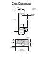
CASE DIMENSIONS
END
28 11/16 in
[728.3 cm]
MODEL
ONNA-3'
AMP PLATE &
SERIAL PLATE
LOCATION
51 5/8 in
[1311.6 cm]
85 9/16 in
[2174.1 cm]
17 5/16 in
[439.4 cm]
COIL
FAN
16 7/8 in
[428.1 cm]
12 5/16 in
[312.4 cm]
25 1/2 in
[647.3 cm]
26 1/2 in
[673.4 cm]
CONDENSING UNIT
DRAIN PAN
14 1/2 in
[36.8 cm]
25 1/2 in
[64.8 cm]
28 5/8 in
[72.7 cm]
1 1/2 in [3.8 cm]
{END}
DRAIN ASSEMBLY
JUNCTION BOX
BACK OF CASE
39 3/16 in [99.5- cm]
(Polymer Trim)
4
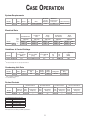
CASE OPERATION
System Requirements
Model
ONNA
3'
Volts
Phase
Hz
Wire
Minimum
Circuit
Ampacity
120
1
60
2 wire + ground
15.5
Maximum
Overcurrent
Protection
Connection Plug
20
NEMA - L5-20
Electrical Data
Model
ONNA
3'
Condenser
Fans
Standard Fans
Evaporator
Pan Heater
Drain
Pump
Drain
Heater
Fans
per
Case
Amps
Watts
Amps
Watts
Amps
Watts
Amps
Watts
Amps
Watts
2
0.68
34
0.53
55
1.0
120
4.16
500
0.32
40
120 Volts
120 Volts
120 Volts
120 Volts
120 Volts
Guidelines & Control Settings
Model
ONNA
24 Hour
Energy Usage
(kWh)
Suction Pressure
@ Case Outlet
(psig)
Superheat Set
Point @ Bulb
(°F)
24.3
17
6-8
3'
Discharge Return
Air
Air
(°F)
(°F)
34
Discharge Air Velocity1
(FPM)
46
200
1 Average discharge air velocity at peak of defrost.
Condensing Unit Data
Model
ONNA
3'
Volts
Phase
Frequency
(Hz)
HP
RLA2
(amps)
LRA3
(amps)
Refrigerant
Refrigerant
(lbs.)
120
1
60
1/2
9.30
36.0
R134A
2.20
2 RLA = Running Load Amps.
3 Locked Rotor Amps.
Defrost Controls
Electric Defrost
Model
ONNA
3'
Timed Off Defrost
Hot Gas Defrost
Reverse Air Defrost
Defrosts
Per Day
FailSafe
(min)
Termination
Temp (°F)
FailSafe
(min)
Termination
Temp (°F)
FailSafe
(min)
Termination
Temp (°F)
FailSafe
(min)
Termination
Temp (°F)
6
---
---
28
52
---
---
---
---
Low Temperature Defrost Schedule
No. Per Day
Hours
1
2
3
4
12 midnight
12 am - 12pm
6 am - 2pm - 10pm
12 am - 6am - 12pm - 6pm
All measurements are taken per CRMA specifications.
5
INSTALLATION
The ONNA-3' is shipped with most of the exterior panels
and trim already installed. The only exterior parts that need
to be installed when the case arrives are the kickplate and
the back lower-panel.
For lower back-panel installation, slide the back-panel up
under the channels, then use the supplied screws to fasten
to the baseframe (see illustration below for details).
The kickplate, which is shipped in the case, simply slips
upward behind the front panel and then down onto the
baseframe.
KICKPLATE
FRONT PANEL
KICKPLATE
BASE FRAME
LOWER BACK-PANEL
LOWER BACK PANEL
BLACK TEK
SCREWS
LOWER BACK PANEL
6
PLUMBING
All of the plumbing components are attached to the case at the factory; therefore, no assembly is required. The case drain
is located front-and-center of the cases for convenient access and is made of cast metal. The “P” trap, furnished with
the case, is made from PVC pipe. Should any future maintenance issues arise, care should be given to assure that all
connections are water-tight and sealed with the appropriate PVC cement and primer.
The case run-off is channeled to a condensate pump located underneath the case as shown below. The water is then
pumped to an evaporative drain pan on top of the case, where an electric heater evaporates the run-off. When cleaning
the case, be sure not to introduce water faster than the drain pump can carry it away.
EVAPORATIVE
DRAIN PAN
MODEL
ONNA-3'
NOTE: When cleaning the case, do not introduce water
faster than the drain pump can carry it away.
CONDENSATE
PUMP
7
REFRIGERATION COMPONENTS
Access Valve - Access port on the evaporator that allows
service personnel to check system
pressure.
eration system that removes water and other impurities
from the refrigerant in the lines during initial start-up.
Receiver - The component in a refrigeration system that
stores liquid refrigerant that is not being used by the system
in low load conditions or when the system is shut down.
Accumulator - A device installed on the suction line that is
used to boil off small amounts of liquid refrigerant so liquid
does not reach the compressor.
Service Valve - A manually operated valve in the refrigeration system that is used for various service operations such
as isolating the high or low sides of the system.
Compressor - An electrically driven piston pump that
pumps vapor refrigerant from a low pressure level to a
higher pressure level.
Sight Glass - A device installed on the liquid line of a refrigeration system that is used to determine if there is water or
vapor in the lines by visual inspection.
Condenser - The component in a refrigeration system that
transfers the heat that was absorbed by the refrigerant in
the evaporator and the heat of compression from the system by condensing the refrigerant.
Thermostatic Expansion Valve (TXV) - A valve that controls the flow of liquid refrigerant to the evaporator coil and
also separates the high pressure side of the system from
low pressure side of the system.
Condenser Fans - Fan that forces air through the air
cooled condenser to aid heat transfer.
Dual-Pressure Control - A device that protects the compressor from low charge and high pressure.
Thermostatic Expansion Valve (TXV) Bulb - A bulb that is
attached to the suction line of the evaporator that controls
the TXV. Inside the bulb is a charge that reacts to temperature and regulates the flow of refrigerant through the expansion valve.
Evaporator - The component of the refrigeration system
that absorbs heat from the air by boiling liquid refrigerant to
vapor.
Evaporator Fans - Fans that circulate air through the case
and force air through the evaporator to aid heat transfer.
Filter Drier - A device installed on the liquid line of a refrig-
8
REFRIGERATION PIPING
The diagram below illustrates all of the refrigeration components in the ONNA-3'. The components surrounded by the
box are located in the case tank. Basic definitions of these
components are listed on the preceding page.
The expansion valve and other controls are located on the
left-hand side of the case and are accessible without lifting
the fan plenum.
The controls cluster may be reached by lifting only the left
hand deck pan minimizing the need to unload product. The
compressor and condensing unit are located on top of the
case for easy access.
If it becomes necessary to penetrate the case bottom for
any reason, make certain it is sealed afterward with cannedfoam sealant and white RTV.
MODEL
ONNA-3'
Evaporator
Tank
Area
TXV
Bulb
1/4”
Access
Valve
TXV
Evaporator
Fans
Flow Direction
Flow Direction
Dual Pressure
Control
Accumulator
Filter
Drier
Condenser
Sight
Glass
Service
Valve
Service
Valve
Compressor
Receiver
Condenser
Fans
9
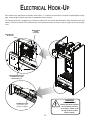
ELECTRICAL HOOK-UP
No in-field wiring is required for installation of the ONNA - 3': all electrical connections have been completed prior to shipping. Simply plug the power chord into an appropriate electrical outlet.
The condensate pump is plugged into a receptacle mounted in the junction box, behind the front removable panel (see
below). NOTE: the receptacle is intended for use with the drain pump only and not as a power supply for any other equipment.
MAIN POWER
CHORD
LOCATION
EVAPORATIVE
DRAIN PAN
EVAPORATIVE DRAIN PAN
& CONDENSATE PUMP
RECEPTACLES (2)
DANGER
SHOCK HAZARD
Always disconnect power
to case when servicing
or cleaning. Failure to do
so may result in serious
injury or death.
CONDENSATE PUMP
(connected to junction box receptacle)
10
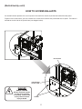
(Electrical Hook-Up, cont'd)
HOW TO ACCESS BALLASTS
An electronic ballast operates the case lamp and is located in the electrical junction box behind the front panel.
To gain access to the ballast, you must remove the 2 screws on the front of the junction box access panel. The ballast is
located on the left side of the junction box (see diagram below).
BALLAST BOX
JUNCTION BOX
ACCESS PANEL
DANGER
SHOCK HAZARD
Always disconnect power
to case when servicing
or cleaning. Failure to do
so may result in serious
injury or death.
SCREWS
11
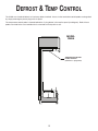
DEFROST & TEMP CONTROL
The ONNA uses timed-off defrost as its primary defrost method. Access to the termination control probe can be gained
by simply removing the plastic plug in the flu-panel.
The temperature control probe is located behind the 3” plug button in the top flue panel (see diagram). Both of these
probes are wired to the case controller that is mounted on the top of the case.
MODEL
ONNA
TEMPERATURE CONTROL
PROBE LOCATION
(behind the 3” plug button).
12
AIR FLOW & PRODUCT LOADING
Cases have been designed to provide maximum product capacity within the refrigerated air envelope. It is important
that you DO NOT overload the food product display to avoid impinging on the air flow pattern.
Overloading will cause malfunction and the loss of proper temperature levels, particularly when discharge and return air
sections are covered. Please keep products within the load-limit lines shown on in the diagram below.
MODEL
ONNA
DISCHARGE................1
LOAD LIMIT.................2
1
AIR FLOW....................3
RETURN AIR GRILL...4
2
3
4
13
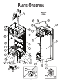
PARTS ORDERING
8
MODEL
ONNA
9
24
17
30
29
28
29
32
23
22
38
31
7
21
33
25
3
6
16
40
13
5
11
15
36
10
20
12
37
2
1
35
34
18
19
4
39
14
E09
26
50
27
E06
E07
E10
E11
14
(Part Ordering, cont'd)
Location
Number
Location
Number
Part Descriptions
1
2
3
4
5
6
7
8
9
Pump Bracket
March Pump Model
Upper Back Panel
Rear Pipe & Wiring Covers
Lower Rear Baffle
Upper Rear Baffle
Flue Panel
Rear Honeycomb Container
Plastic Honeycomb (indicate
color)
Lower Front Panel
Master Bumper
Nose Bumper
Front Baffle Deflector
Lower Back Panel
Deck Pan
Wire Rack
Front Honeycomb Retainer
Plexiglass Retainer
Plexiglass
Front Baffle
Lightrod Canopy
Light Support Bracket
Light Support Stiffener
Light Curtain
10
11
12
13
14
15
16
17
18
19
20
21
22
23
24
25
26
27
28
29
30
31
32
33
34
35
36
37
38
39
40
41
50
E06
E07
E09
E10
E11
E20
Part Descriptions
Top-Front Lower Pan
Magnet Support Bracket
Catch Magnet
Removal Corner (upper front)
Left Cover Joint Trim
Right Cover Joint Trim
Air Deflector
Filter Bracket
Kickplate
Spectra Bumper
Spectra McCue Bumper
CGE McCue Bumper
Night Curtain Retainer
Upper-Rear Fascia
Plug Button
Shelf
Evaporative Drain Pan
Lamp Shield
Lamp Holder
Lamp
Fan Motor (indicate Standard or
High Efficiency)
Fan Blade
Fan Basket
Fan Cord-Set (indicate Standard
or High Efficiency)
Order Procedure
1. Contact the Service Parts Department at 1-800-283-1109.
2. Provide the following information about the part you are ordering:
• Model number and serial number of the case on which the part is used.
• Length of part, if applicable, I.E. 36”.
• Color of part if painted, or color of polymer part.
• Whether part is for left hand or right hand application.
• Whether shelves are with or without lights.
• Quantity
*Serial plate is located on top flue panel on the right hand side of the case (See illustrations on page 3).
3. If parts are to be returned for credit, ask the Parts Department to furnish you with a Return Material
Authorization Number.
15
APPENDIX A:
WIRING DIAGRAMS
APPENDIX B:
CONTROL SETTINGS
DIGITAL CONTROLLER
XR03CX
1. CONTENTS
1.
2.
3.
4.
5.
6.
7.
8.
9.
10.
11.
12.
13.
14.
1.
2.
•
•
•
•
•
•
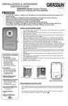
3. GENERAL DESCRIPTION
Model XR03CX, format 32 x 74 x 50 mm, is a digital thermostat with off cycle defrost designed for refrigeration
applications at normal temperature. It provides a relay output to drive the compressor. It is also provided with 2 NTC
probe input. The instrument is fully configurable through special parameters that can be easily programmed through the
keyboard or the by HOTKEY.
4. REGULATION
HIDDEN MENU
The hidden menu includes all the parameters of the instrument .HOW TO ENTER THE HIDDEN MENU
1. Enter the Programming mode by pressing the SET+
keys for 3s (“°C” or “°F” LED starts blinking).
2. Released the keys, then push again the SET+
keys for more than 7s. The L2 label will be displayed
immediately followed from the Hy parameter.
NOW YOU ARE IN THE HIDDEN MENU.
3. Select the required parameter.
4. Press the “SET” key to display its value
5. Use
or
to change its value.
6. Press “SET” to store the new value and move to the following parameter.
To exit: Press SET+
or wait 15s without pressing a key.
NOTE1: if no parameters are present in L1, after 3s the “nP” message is displayed. Keep the keys pushed till
the L2 message is displayed.
NOTE2: the set value is stored even when the procedure is exited by waiting the time-out to expire.
HOW TO MOVE A PARAMETER FROM THE HIDDEN MENU TO THE FIRST LEVEL
AND VICEVERSA.
Each parameter present in the HIDDEN MENU can be removed or put into “THE FIRST LEVEL” (user level) by
pressing SET+ . In HIDDEN MENU when a parameter is present in First Level the decimal point is on.
1.
2.
The regulation is performed according to
the temperature measured by the
thermostat probe with a positive differential
from the set point: if the temperature
increases and reaches set point plus
differential the compressor is started and
then turned off when the temperatur
Press for more than 3s the
and
keys together.
The “OF” message will be displayed and the keyboard will be locked. If a key is pressed more than 3s
the “OF” message will be displayed.
TO UNLOCK THE KEYBOARD
Press together for more than 3s the
and
keys till the “on” message will be displayed.
7. PARAMETERS
.
In case of fault in the thermostat probe the start and stop of the compressor are timed through parameters “Cy” and
“Cn”.
5. DEFROST
Defrost is performed through an off cycle of the compressor. Parameter “id” controls the interval between
defrost cycles, while its length is controlled by parameter “nd”. A defrost indicator light will illuminate during
defrost and also after the defrost ends according to parameter “Fd”
6. FRONT PANEL COMMANDS
To display target set point, in
programming mode it selects a
parameter or confirm an
operation
To start a manual defrost
AUX
In programming mode it
browses the parameter codes or
increases the displayed value
In programming mode it
browses the parameter codes or
decreases the displayed value
To lock or unlock the keyboard
To enter in programming mode
SIGNIFICATO
On
Flashing
On
Compressor enabled
Anti short cycle delay enabled (AC parameter)
Defrost in progress
Ld
Default display: (P1 ÷ P2) P1= thermostat probe; P2= evaporator probe. SP=Set point
dy
Display delay: (0÷15 min.) when the temperature increases, the display is updated of 1 °C/1°F after this
time.
nd
To return to room temperature display
MODO
REGULATION
Hy Differential: (0,1°C ÷ 25°C) Intervention differential for set point. Compressor Cut IN is SET POINT +
differential (Hy). Compressor Cut OUT is when the temperature reaches the set point.
LS Minimum SET POINT: (-55°C÷SET/-58°F÷SET): Sets the minimum value for the set point..
US Maximum SET POINT: (SET÷99°C/ SET÷99°F). Set the maximum value for set point.
ot First probe calibration: (-9.9÷9.9°C) allows to adjust possible offset of the first probe.
P2 Evaporator probe presence: n= not present; y= the defrost stops by temperature.
oE Second probe calibration: (-9.9÷9.9°C) allows to adjust possible offset of the second probe
AC Anti-short cycle delay: (0÷50 min) minimum interval between the compressor stop and the following
restart.
Cy Compressor ON time with faulty probe: (0÷99 min) time during which the compressor is active in case
of faulty thermostat probe. With Cy=0 compressor is always OFF.
Cn Compressor OFF time with faulty probe: (0÷99 min) time during which the compressor is OFF in case
of faulty thermostat probe. With Cn=0 compressor is always active.
DISPLAY
CF Measurement unit: (°C÷°F) °C =Celsius; °F =Fahrenheit. WARNING: When the measurement unit is
changed the SET point and the values of the parameters Hy, LS, US, oE, o1, AU, AL have to be
checked and modified if necessary).
rE Resolution (only for °C):(dE ÷ in) dE= decimal between -9.9 and 9.9°C; in= integer;
DEFROST
dE Defrost termination temperature: (-50÷50°C) if ot=Y it sets the temperature measured by the
evaporator probe, which causes the end of defrost.
id Interval between defrost cycles: (0÷99 ore) Determines the time interval between the beginning of two
defrost cycles.
KEYS COMBINATION
XR03CX-HF.doc
To change the parameter’s value operate as follows:
1. Enter the Programming mode by pressing the SET+
keys for 3s (“°C” or “°F” LED starts blinking).
2. Select the required parameter. Press the “SET” key to display its value
3. Use
or
to change its value.
4. Press “SET” to store the new value and move to the following parameter.
To exit: Press SET+
or wait 15s without pressing a key.
NOTE: the set value is stored even when the procedure is exited by waiting the time-out to expire.
TO LOCK THE KEYBOARD
THE REGULATION OUTPUT
LED
key for more than 2 seconds and a manual defrost will start
HOW TO CHANGE A PARAMETER VALUE
Check the supply voltage is correct before connecting the instrument.
Do not expose to water or moisture: use the controller only within the operating limits avoiding sudden
temperature changes with high atmospheric humidity to prevent formation of condensation
Warning: disconnect all electrical connections before any kind of maintenance.
Fit the probe where it is not accessible by the End User. The instrument must not be opened.
In case of failure or faulty operation send the instrument back to the distributor or to “Dixell S.p.A.” (see address)
with a detailed description of the fault.
Consider the maximum current which can be applied to each relay (see Technical Data).
Ensure that the wires for probes, loads and the power supply are separated and far enough from each other,
without crossing or intertwining.
In case of applications in industrial environments, the use of mains filters (our mod. FT1) in parallel with inductive
loads could be useful.
+
+
Push and immediately release the SET key, the set point will be shown;
Push and immediately release the SET key or wait about 5s to return to normal visualisation.
Push the DEF
This manual is part of the product and should be kept near the instrument for easy and quick reference.
The instrument shall not be used for purposes different from those described hereunder. It cannot be used as a
safety device.
Check the application limits before proceeding.
+
Measurement unit
Programming mode
Measurement unit
Programming mode
HOW TO START A MANUAL DEFROST (ONLY XR02CX)
SAFETY PRECAUTIONS
•
•
On
Flashing
On
Flashing
HOW TO CHANGE THE SETPOINT
1.
Push the SET key for more than 2 seconds to change the Set point value;
2.
The value of the set point will be displayed and the “°C” or “°F” LED starts blinking;
3.
To change the Set value push the
or
arrows within 10s.
4.
To memorise the new set point value push the SET key again or wait 10s.
PLEASE READ BEFORE USING THIS MANUAL
•
Defrost in progress
HOW TO SEE THE SET POINT
Contents ___________________________________________________________________________ 1
General warnings ____________________________________________________________________ 1
General description___________________________________________________________________ 1
Regulation__________________________________________________________________________ 1
Defrost ____________________________________________________________________________ 1
Front panel commands ________________________________________________________________ 1
Parameters _________________________________________________________________________ 1
Installation and mounting ______________________________________________________________ 2
Electrical connections _________________________________________________________________ 2
How to use the hot key ________________________________________________________________ 2
Alarm signalling______________________________________________________________________ 2
Technical data_______________________________________________________________________ 2
Connections ________________________________________________________________________ 2
Default setting values _________________________________________________________________ 2
2. GENERAL WARNINGS
•
•
On
dF
XR03CX Maximum length for defrost: (0÷99 min. with 0 no defrost) when P2 = n, (no evaporator probe: timed
defrost) it sets the defrost duration, when P2 = y (defrost end based on temperature) it sets the maximum
length for defrost.
Display during defrost: (rt / it / St / dF) rt= real temperature; it= start defrost temperature; St= SETPOINT; dF= label dF.
1/2
dP Defrost start after Power failure: (n - y) n= the defrost clock will reset; y= start defrost after a power
failure
Fd Defrost indicator delay: (0 – 99 min) the time delay that the defrost indicator light will stay on after a
defrost
ALARMS
AU Maximum temperature alarm: (AL÷99°C) when this temperature is reached the alarm is enabled, after
the “Ad” delay time.
AL Minimum temperature alarm: (-55÷AU°C) when this temperature is reached the alarm is enabled, after
the “Ad” delay time.
Ad Temperature alarm delay: (0÷99 min) time interval between the detection of an alarm condition and
alarm signalling.
dA Exclusion of temperature alarm at startup: (0÷99 min) time interval between the detection of the
temperature alarm condition after instrument power on and alarm signalling.
OTHER
d2
Pt
rL
Data storing: on the non-volatile memory (EEPROM).
Kind of action: 1B; Pollution grade: 2; Software class: A.;
Rated impulsive voltage: 2500V; Overvoltage Category: II
Ambient temperature: 0÷60 °C; Storage temperature: -30÷85 °C.
Relative humidity: 20÷85% (no condensing)
Measuring and regulation range: NTC -40÷110°C (-40÷230°F);
Resolution: 0,1 °C or 1°C or 1 °F (selectable); Accuracy (ambient temp. 25°C): ±0,7 °C ±1 digit
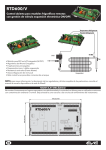
13. CONNECTIONS
NOTE: Fast-on
maximum current
16A
Evaporator probe display (read only)
Parameter code table
Software release
8. INSTALLATION AND MOUNTING
Instrument XR03CX shall be mounted on vertical panel, in a
29x71 mm hole, and fixed using the special bracket supplied.
The temperature range allowed for correct operation is 0÷60 °C.
Avoid places subject to strong vibrations, corrosive gases,
excessive dirt or humidity. The same recommendations apply to
probes. Let air circulate by the cooling holes.
14. DEFAULT SETTING VALUES
DESCRIPTION
LBL
RANGE
DEFAULT
LEVEL
REGULATION
9. ELECTRICAL CONNECTIONS
The instrument is provided with Fast-on connections. Before connecting cables make sure the power supply
complies with the instrument’s requirements. Separate the probe cables from the power supply cables, from
the outputs and the power connections. Do not exceed the maximum current allowed on each relay, in case of
heavier loads use a suitable external relay.
9.1 PROBES
The probes shall be mounted with the bulb angled upward to prevent damages due to casual liquid infiltration.
It is recommended to place the thermostat probe away from air streams to correctly measure the average room
temperature. Place the defrost termination probe among the evaporator fins in the coldest place, where most
ice is formed to prevent premature defrost termination.
Hy
Differential
1 ÷ 45°F
2 °F
L1
LS
Minimum Set Point
-67°F÷SET
25°F
L2
US
Maximum Set Point
SET÷99°F
40°F
L2
ot
First probe calibration
-18 +18°F
0°F
L2
P2
Second probe presence
n–Y
y
L2
oE
Second probe calibration
18 +18°F
0°F
L2
AC
Anti-short cycle delay
0 ÷ 50 min
2
L2
Cy
Compressor ON time faulty probe
0 ÷ 99 min
12
L2
Cn
Compressor OFF time faulty probe
0 ÷ 99 min
4
L2
DISPLAY
10. HOW TO USE THE HOT KEY
10.1 HOW TO PROGRAM THE HOT KEY FROM THE INSTRUMENT (UPLOAD)
1. Program one controller with the front keypad.
2. When the controller is ON, insert the “Hot key” and push
key; the "uP" message appears followed a
by flashing “En”
3. Push “SET” key and the “En” will stop flashing.
4. Turn OFF the instrument remove the “Hot Key”, then turn it ON again.
NOTE: the “Er” message is displayed for failed programming. In this case push again o key if you want to
restart the upload again or remove the “Hot key” to abort the operation.
10.2 HOW TO PROGRAM AN INSTRUMENT USING HOT KEY (DOWNLOAD)
1. Turn OFF the instrument.
2. Insert a programmed “Hot Key” into the 5 PIN receptacle and then turn the Controller ON.
3. Automatically the parameter list of the “Hot Key” is downloaded into the Controller memory, the “do”
message is blinking followed a by flashing “En”.
4. After 10 seconds the instrument will restart working with the new parameters.
5. Remove the “Hot Key”..
NOTE: the “Er” message is displayed for failed programming. In this case push again o key if you want to
restart the upload again or remove the “Hot key” to abort the operation.
CF
Measurement units
°C - °F
°F
L2
rE
Resolution (only for °C)
dE – in
in
L2
Ld
Default Display
P1 - P2
P1
L2
dy
Display delay
0 ÷ 15 min
0
L2
DEFROST
dE
Defrost termination temperature
58÷99°F
52 °F
L1
id
Interval between defrost cycles
0 ÷ 99 hours
4
L1
nd
Maximum length for defrost
0 ÷ 99 min.
28
L1
dF
Display during defrost
rt – it – dF - St
rt
L2
dP
Defrost After Power Failure
n- y
y
L2
Fd
Defrost Indicator delay after defrost
0 – 99min
20
L2
ALARMS
11. ALARM SIGNALLING
AU
Maximum temperature alarm
ALL÷99°F
55 °F
L2
Mess.
"P1"
"P2"
"HA"
"LA"
“EA”
“CA”
“nP’
“dA”
AL
Minimum temperature alarm
-55°C÷ALU/67°F÷ALU
20 °F
L2
Ad
Temperature alarm delay
0 ÷ 99 min
5
L2
dA
temperature alarm delay at startup
0 ÷ 99 min
90
L2
d2
Evaporator probe display
Read Only
---
L1
Pt
Parameter code table
Read Only
---
L2
rL
Firmware release
Read Only
---
L2
Cause
Room probe failure
Evaporator probe failure
Maximum temperature alarm
Minimum temperature alarm
External alarm
Serious external alarm
No Parameters in L1
Door Open
Outputs
Compressor output according to “Cy” e “Cn”
Defrost end is timed
Outputs unchanged
Outputs unchanged
Outputs unchanged
All outputs OFF.
Outputs unchanged
Compressor and fans restart
OTHER
11.1 ALARM RECOVERY
Probe alarms P1” and “P2” start a few seconds after the fault in the related probe; they automatically stop a
few seconds after the probe restarts normal operation. Check connections before replacing the probe,
Temperature alarms “HA” and “LA” automatically stop as soon when temperature returns to normal values.
Alarms “EA” and “CA” (with iF=bL) recover as soon as the digital input is disabled.
12. TECHNICAL DATA
Housing: self extinguishing ABS.
Case: frontal 32x74 mm; depth 60mm;
Mounting: panel mounting in a 71x29mm panel cut-out
Protection: IP20; Frontal protection: IP65
Connections: disconnectable terminal block ≤ 2,5 mm2 wiring and 6.3mm fast-on’s
Power supply: according to the model ±10%; 230Vac ±10%, 50/60Hz, 110Vac ±10%, 50/60Hz
Power absorption: 3.5 VA max
Display: 2 digits, red LED, 14,2 mm high; Inputs: 2 NTC Probes
Relay outputs: compressor; 16FLA/96LRA, AUX: 10A
XR03CX-HF.doc
XR03CX 2/2
APPENDIX C:
USE & MAINTENANCE
IN- STORE SERVICE FOR ONNA-3
DANGER
Electrical Shock Hazard
Always disconnect power to
case when servicing or
cleaning.
WARNING
HIGH
PRESSURESwitch Off Both Power Switches
Before Pre-Cleaning Case.
5. Make sure the drain is free of any obstructions.
6. Using only a wet cloth and a bucket of clear water,
wipe the case; never use a hose on a Self-Contained case with an evaporative pan.
PRE-CLEANING
1. Relocate product to alternate refrigerated storage
area, then turn off condensing unit and main power.
HIGH
PRESSURE
2. Both switches are located behind the upper access
door.
7. DO NOT flood the case. Never introduce water faster then the waste outlet can remove it. The drain
system is self-contained and pumps all the liquids
to the top of the case for evaporation.
CAUTION
The heating element in the
evaporator pan is very hot when
on.
HIGH
PRESSURE
8. DO NOT use hot or warm water on cold glass surfaces. This may shatter the glass and could result
in personal injury. Allow all glass to warm before
applying hot or warm water.
3. Avoid Abrasive scouring powders or pads. DO NOT
use cleaners containing abrasive materials or ammonia which will scratch or damage the finish.
9. Avoid spraying cleaning solutions directly on fans
or electrical connections.
4. Use mild cleaning solutions and warm water when
necessary. A water and baking soda solution will
help remove case odors.
10. DO NOT FORCE REMOVAL OF ICE AS THIS MAY
CAUSE DAMAGE.
1
P071253M SERVICE REV 0
IN- STORE SERVICE FOR ONNA-3
WARNING
Verify Both Power Switches Are
Off Before Cleaning Case.
CLEANING
1. Verify that both switches were turned are OFF during pre-cleaning. Both switches are located behind
the upper access door.
HIGH
PRESSURE
6. Spray shelves (starting at top) with a mild cleaning solution. Wipe each shelf (starting at the top,)
ensuring that the grove in the tag moldings is thoroughly cleaned.
2. Always clean from the top down.
7. Use a "no rinse" cleaning solution when cleaning
the tank. Follow the manufactures directions. Never
allow water to flood the tank.
3. Remove all product stops, wire racks, removable
tag moldings and deck pans.
4. Remove and clean the honeycomb discharge grill.
A sink filled with warm sudsy water will simplify
this task. It may be necessary to use spray detergent and a soft, long- bristle brush to get deep dirt.
8. Spray the exterior of case with mild cleaning solution then wipe down with a cloth or paper towel.
SANITIZING
1. Replace all tag molding, product stops and shelves
removed during cleaning.
2. Spray the entire case including the coil, and tank
area with sanitizer.
3. Allow to air dry. Any water remaining on the coil will
turn into ice.
4. Replace remaining case components, deck pans,
wire shelves and honeycomb.
5. Turn both switches ON. Both switches are located
behind the upper access door.
6. Allow case to return to temperature BEFORE returning product to case.
5. Spray rear baffles (rear of case) with a mild cleaning solution, then wipe with a cloth or paper towels.
2
P071253M SERVICE REV 0
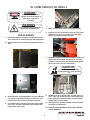
IN- STORE SERVICE FOR ONNA-3
CAUTION
FILTER CHANGING
The heating element in the
evaporator pan is very hot when
on.
In store service is limited and can be completed in just
a few minutes each week. HIGH
PRESSURE
1. Make sure that both switches are tuned OFF before
starting to service the case. They are located just
behind the upper access door.
6. Before cleaning the evaporator pan ensure that it
has been unplugged, and allow to cool. Wipe the
inside of the evaporator pan to remove residue and
any debris that may have fallen into the chamber.
2. Unplug both the sump pump and the evaporator
heater pan from the duplex plug.
7. Ensure that the float can move freely.
8. Plug back in the Sump Pump and evaporator
heater.
3. Remove the condenser filter element from the
holder and replace it with a new one (P071083A)
9. Turn on both switches, located just behind the upper access door.
4. While the filter is
removed check
to see if the fins
on the condenser
are clean. If not,
using care, a shop
vacuum and a soft
brush attachment
clean any dirt or
dust from the fins.
5. DO NOT bend
any fins during
filter change or
cleaning operation. The case
performance WILL
BE REDUCED.
3
CLEANING PRODUCTS
Use the following specialty cleaning products for difficult stains that may appear:
•
Armor All© for polymer parts
•
3M brand© Stainless Steel Cleaner and Polish
•
3M brand© Troubleshooter Cleaner
•
3M brand© Sharpshooter, Extra Strength No
Rinse Cleaner
•
Revere© aluminum powder for tank liner
QUESTIONS?
If you have any questions or concerns, please contact Hill
PHOENIX at 1-800-283-1109 (select extension “2444”).
P071253M SERVICE REV 0
NOTES
NOTES
WARRANTY
HEREINAFTER REFERRED TO AS MANUFACTURER
FOURTEEN MONTH WARRANTY. MANUFACTURER’S PRODUCT IS WARRANTED TO BE FREE FROM
DEFECTS IN MATERIAL AND WORKMANSHIP UNDER NORMAL USE AND MAINTENANCE FOR A PERIOD OF
FOURTEEN MONTHS FROM THE DATE OF ORIGINAL SHIPMENT. A NEW OR REBUILT PART TO REPLACE
ANY DEFECTIVE PART WILL BE PROVIDED WITHOUT CHARGE, PROVIDED THE DEFECTIVE PART IS RETURNED
TO MANUFACTURER. THE REPLACEMENT PART ASSUMES THE UNUSED PORTION OF THE WARRANTY.
This warranty does not include labor or other costs incurred for repairing, removing, installing, shipping, servicing, or
handling of either defective parts or replacement parts.
The fourteen month warranty shall not apply:
1. To any unit or any part thereof which has been subject to accident, alteration, negligence, misuse or
abuse, operation on improper voltage, or which has not been operated in accordance with the
manufacturer’s recommendation, or if the serial number of the unit has been altered, defaced, or removed.
2. When the unit, or any part thereof, is damaged by fire, flood, or other act of God.
3. Outside the continental United States.
4. To labor cost for replacement of parts, or for freight, shipping expenses, sales tax or upgrading.
5. When the operation is impaired due to improper installation.
6. When installation and startup forms are not properly complete or returned within two weeks after startup.
THIS PLAN DOES NOT COVER CONSEQUENTIAL DAMAGES. Manufacturer shall not be liable under any circumstances for any consequential damages, including loss of profit, additional labor cost, loss of refrigerant or food products, or injury to personnel or property caused by defective material or parts or for any delay in its performance hereunder due to causes beyond its control. The foregoing shall constitute the sole and exclusive remedy of any purchases and the sole and exclusive liability of Manufacturer in connection with this product.
The Warranties are Expressly in Lieu of All Other Warranties, Express of Implied and All Other Obligations or
Liabilities on Our Part. The Obligation to Repair or Replace Parts or Components Judged to be Defective in
Material or Workmanship States Our Entire Liability Whether Based on Tort, Contract or Warranty. We Neither
Assume Nor Authorize Any Other Person to Assume for Us Any Other Liability in Connection with Our Product.
MAIL CLAIM TO:
Hill PHOENIX
Hill PHOENIX
Display Merchandisers
1925 Ruffin Mill Road
Colonial Heights, VA 23834
1-800-283-1109
Refrigeration Systems &
Electrical Distribution Products
709 Sigman Road
Conyers, GA 30013
770-285-3200
09/08
Warning
Maintenance & Case Care
When cleaning cases the following must be performed
PRIOR to cleaning:
To avoid electrical shock, be sure all electric power is
turned off before cleaning. In some installations, more
than one switch may have to be turned off to completely de-energize the case.
Do not spray cleaning solution or water directly on fan
motors or any electrical connections.
All lighting receptacles must be dried off prior to insertion and re-energizing the lighting circuit.
Please refer to the Use and Maintenance section of this installation manual.
1925 Ruffin Mill Road, Colonial Heights, VA 23834
Due to our commitment to continuous improvement all specifications are subject to change without notice.
Hill PHOENIX is a Sustaining Member of the American Society of Quality.
Visit our web site at www.hillphoenix.com
BDM0917